US5820656A - Process and apparatus for gas separation - Google Patents
Process and apparatus for gas separation Download PDFInfo
- Publication number
- US5820656A US5820656A US08/787,183 US78718397A US5820656A US 5820656 A US5820656 A US 5820656A US 78718397 A US78718397 A US 78718397A US 5820656 A US5820656 A US 5820656A
- Authority
- US
- United States
- Prior art keywords
- valve
- apertures
- passage means
- valve assembly
- adsorption
- Prior art date
- Legal status (The legal status is an assumption and is not a legal conclusion. Google has not performed a legal analysis and makes no representation as to the accuracy of the status listed.)
- Expired - Fee Related
Links
Images


Classifications
-
- F—MECHANICAL ENGINEERING; LIGHTING; HEATING; WEAPONS; BLASTING
- F16—ENGINEERING ELEMENTS AND UNITS; GENERAL MEASURES FOR PRODUCING AND MAINTAINING EFFECTIVE FUNCTIONING OF MACHINES OR INSTALLATIONS; THERMAL INSULATION IN GENERAL
- F16K—VALVES; TAPS; COCKS; ACTUATING-FLOATS; DEVICES FOR VENTING OR AERATING
- F16K11/00—Multiple-way valves, e.g. mixing valves; Pipe fittings incorporating such valves
- F16K11/02—Multiple-way valves, e.g. mixing valves; Pipe fittings incorporating such valves with all movable sealing faces moving as one unit
- F16K11/06—Multiple-way valves, e.g. mixing valves; Pipe fittings incorporating such valves with all movable sealing faces moving as one unit comprising only sliding valves, i.e. sliding closure elements
- F16K11/072—Multiple-way valves, e.g. mixing valves; Pipe fittings incorporating such valves with all movable sealing faces moving as one unit comprising only sliding valves, i.e. sliding closure elements with pivoted closure members
- F16K11/074—Multiple-way valves, e.g. mixing valves; Pipe fittings incorporating such valves with all movable sealing faces moving as one unit comprising only sliding valves, i.e. sliding closure elements with pivoted closure members with flat sealing faces
- F16K11/0743—Multiple-way valves, e.g. mixing valves; Pipe fittings incorporating such valves with all movable sealing faces moving as one unit comprising only sliding valves, i.e. sliding closure elements with pivoted closure members with flat sealing faces with both the supply and the discharge passages being on one side of the closure plates
-
- B—PERFORMING OPERATIONS; TRANSPORTING
- B01—PHYSICAL OR CHEMICAL PROCESSES OR APPARATUS IN GENERAL
- B01D—SEPARATION
- B01D53/00—Separation of gases or vapours; Recovering vapours of volatile solvents from gases; Chemical or biological purification of waste gases, e.g. engine exhaust gases, smoke, fumes, flue gases, aerosols
- B01D53/02—Separation of gases or vapours; Recovering vapours of volatile solvents from gases; Chemical or biological purification of waste gases, e.g. engine exhaust gases, smoke, fumes, flue gases, aerosols by adsorption, e.g. preparative gas chromatography
- B01D53/04—Separation of gases or vapours; Recovering vapours of volatile solvents from gases; Chemical or biological purification of waste gases, e.g. engine exhaust gases, smoke, fumes, flue gases, aerosols by adsorption, e.g. preparative gas chromatography with stationary adsorbents
- B01D53/0407—Constructional details of adsorbing systems
- B01D53/0446—Means for feeding or distributing gases
-
- B—PERFORMING OPERATIONS; TRANSPORTING
- B01—PHYSICAL OR CHEMICAL PROCESSES OR APPARATUS IN GENERAL
- B01D—SEPARATION
- B01D2253/00—Adsorbents used in seperation treatment of gases and vapours
- B01D2253/10—Inorganic adsorbents
- B01D2253/102—Carbon
-
- B—PERFORMING OPERATIONS; TRANSPORTING
- B01—PHYSICAL OR CHEMICAL PROCESSES OR APPARATUS IN GENERAL
- B01D—SEPARATION
- B01D2256/00—Main component in the product gas stream after treatment
- B01D2256/10—Nitrogen
-
- B—PERFORMING OPERATIONS; TRANSPORTING
- B01—PHYSICAL OR CHEMICAL PROCESSES OR APPARATUS IN GENERAL
- B01D—SEPARATION
- B01D2256/00—Main component in the product gas stream after treatment
- B01D2256/12—Oxygen
-
- B—PERFORMING OPERATIONS; TRANSPORTING
- B01—PHYSICAL OR CHEMICAL PROCESSES OR APPARATUS IN GENERAL
- B01D—SEPARATION
- B01D2259/00—Type of treatment
- B01D2259/40—Further details for adsorption processes and devices
- B01D2259/40003—Methods relating to valve switching
- B01D2259/40005—Methods relating to valve switching using rotary valves
-
- B—PERFORMING OPERATIONS; TRANSPORTING
- B01—PHYSICAL OR CHEMICAL PROCESSES OR APPARATUS IN GENERAL
- B01D—SEPARATION
- B01D53/00—Separation of gases or vapours; Recovering vapours of volatile solvents from gases; Chemical or biological purification of waste gases, e.g. engine exhaust gases, smoke, fumes, flue gases, aerosols
- B01D53/02—Separation of gases or vapours; Recovering vapours of volatile solvents from gases; Chemical or biological purification of waste gases, e.g. engine exhaust gases, smoke, fumes, flue gases, aerosols by adsorption, e.g. preparative gas chromatography
- B01D53/04—Separation of gases or vapours; Recovering vapours of volatile solvents from gases; Chemical or biological purification of waste gases, e.g. engine exhaust gases, smoke, fumes, flue gases, aerosols by adsorption, e.g. preparative gas chromatography with stationary adsorbents
- B01D53/047—Pressure swing adsorption
Definitions
- This invention relates to the separation of gases by pressure swing adsorption (PSA), and more particularly to an adsorption system comprised of a plurality of adsorption vessels arranged in parallel and operated sequentially to provide a quasi-continuous supply of nonadsorbed gas product. Sequencing of the adsorption vessels in the production cycle is controlled by means of an assembly of rotary valves which, by rotation, controls the flow of the various gas streams to and from the adsorption vessels.
- PSA pressure swing adsorption
- Cyclic adsorption processes are generally practiced in batteries of adsorption vessels comprised of two or more adsorbent-filled vessels arranged in parallel and operated out of phase such that at least one vessel is in the adsorption mode while at least one other vessel is in the adsorbent regeneration mode.
- a series of sequential steps including adsorption, equalization and regeneration, are carried out in each vessel.
- the feed, product, and exhaust lines must be provided with valves to permit gas flow through these lines at the appropriate time in the adsorption cycle.
- each vessel of the system is provided with at least three valves, and each valve is opened and closed at least once during each cycle of the process.
- PSA cycles are commonly as short as one minute, accordingly each valve may be required to open and close sixty or more times each hour that the system is in operation. Not only is there considerable wear on each valve over the course of an adsorption run, but considerable energy is expended just to open and close the valves of the system during operation of the plant.
- Adsorption processes are inherently batch-type processes. Nonadsorbed gas product is produced only during the adsorption step and desorbed gas product is produced only during the adsorbent regeneration step of the process. Because of this, the desired product is produced, at best, for no more than one-half of each cycle. Since it is often desirable or necessary that a continuous flow of product be available, for example when oxygen is provided for medical purposes, improvements to adsorption systems and processes which provide better product flow continuity are continually sought. Recently, efforts have been made to develop adsorption systems that operate somewhat like continuous process systems. Some of the more promising new adsorption plant designs are based on the principle of rotation. In some designs the adsorption units rotate through stationary gas zones, while in other designs the adsorption units are stationary while gas flow is sequenced through the various units of the system.
- U.S. Pat. No. 4,925,464 discloses a simple rotary valve assembly for use with adsorption vessels.
- the assembly consists of two valve members which have respectively engaged surfaces that are relatively rotatable to provide valving action.
- valve assembly of this patent permits fluid to flow to and from the various adsorption vessels at appropriate times during the process cycle.
- the disclosure of this patent is incorporated herein by reference.
- a particularly useful pressure equalization method is that known as "outlet-to-outlet equalization", during which fluid flows from the high pressure vessel to the low pressure vessel by flow through the outlets of the vessels. This technique is described in detail in U.S. Pat. No. 5,176,722, the disclosure of which is incorporated herein by reference.
- the invention comprises first and second fluid flow conduits and a multiple valve assembly system for providing selective flow communication between a feed inlet and one or more of the first fluid flow conduits, between one or more of the first fluid flow conduits and an exhaust outlet and between pairs of the second fluid 10 flow conduits.
- the system comprises a first valve assembly having a first valve member ("first valve aperture disk”) and a second valve member ("first valve passage disk”) and a second valve assembly having a first valve member (“second valve aperture disk”) and a second valve member (“second valve passage disk”), and a drive means for causing relative rotation of the valve members of each valve assembly.
- the first valve assembly has a feed inlet and an exhaust outlet.
- the valve members of each assembly have smooth surfaces which are engaged to provide valving action.
- Each valve aperture disk has a set of equally spaced through apertures concentrically disposed about the common center of rotation.
- Each aperture of the valve aperture disk of the first valve aperture disk is in fluid communication with one conduit of the first fluid flow conduits
- each aperture of the second valve aperture disk is in fluid communication with one conduit of the second fluid flow conduits.
- the first valve aperture disk and the second valve aperture disk contain the same number of apertures.
- the first valve passage disk has at least one feed passage means for providing fluid communication between the feed inlet and one or more apertures of the first valve aperture disk and at least one exhaust flow passage means for providing fluid communication between one or more apertures of the first valve aperture disk and the exhaust outlet
- the second valve passage disk has at least one equalization passage means for selectively interconnecting two apertures of the second valve aperture disk.
- the drive means serves to provide relative rotation of the valve aperture disk and valve passage disk of each valve assembly to enable rotationally cycled interconnection and fluid flow between the feed inlet and apertures of the first valve aperture disk, between apertures of the first valve aperture disk and the exhaust outlet, and between pairs of apertures of the second valve aperture disk.
- valve aperture disk of each valve assembly is stationary and the valve passage disk of each valve assembly is rotatable.
- valve aperture disks of the valve assemblies contain the same even number of apertures.
- valve aperture disk of each valve assembly has two apertures
- first valve passage disk has one feed passage means and one exhaust passage means
- second valve passage disk has one equalization passage means for selectively interconnecting two apertures of the second valve aperture disk.
- valve aperture disk of each valve assembly has more than two apertures.
- first valve passage disk has two feed passage means and two exhaust passage means and the second valve passage disk has two equalization passages for selectively interconnecting two apertures of the second valve aperture disk.
- valve aperture disk of each valve assembly has a total of 8, 12, 16 or 20 apertures.
- the drive means produces continuous relative motion of the valve members, and in another embodiment it produces stepwise relative motion of the valve members.
- valve members of the first and second valve assemblies are effected by a single drive means.
- a second aspect of the invention is an adsorption system comprising the above described valve system and an array of adsorption vessels each having a feed inlet end and a product outlet end, with each vessel containing an adsorbent which preferentially adsorbs one or more fluids of a fluid mixture relative to one or more other fluids of the mixture.
- each conduit of the first set of fluid flow conduits is connected to the feed inlet end of one vessel of the array of adsorption vessels and each conduit of the second set of fluid flow conduits is connected to the product outlet end of one vessel of the array of adsorption vessels.
- the adsorption vessels used in the system of the invention may be straight elongate vessels or they may be U-shaped or concentric so that, for example, their inlet ends and outlet ends are adjacent or somewhat adjacent each other.
- the invention is the above-described adsorption system comprising a valve system in which the first valve aperture disk and the second valve aperture disk each have more than two apertures, the first valve passage disk has two feed passage means and two exhaust passage means, and the second valve passage disk has two equalization passage means for selectively interconnecting two apertures of the second valve aperture disk.
- each product passage means is at preferably at least partly located in the radial sector in which a feed passage means is located.
- each purge passage means is preferably located in the radial sector in which an exhaust port is located.
- the radial sector defining each purge port may have a lesser angular extent, i.e. it may be narrower, than the radial sector defining each exhaust port.
- the invention is a process comprising introducing into the feed inlet of the above-described adsorption system, while the valve aperture disk and valve passage disk of each valve assembly are in relative rotation, a fluid mixture which contains a first component which is preferentially adsorbed by the adsorbent contained in the adsorption vessels relative to second component of the fluid mixture, while withdrawing through the product outlet fluid enriched in the second component and withdrawing from the exhaust outlet fluid enriched in the first component and providing outlet-to-outlet equalization between selected vessels of the system.
- the process is particularly suitable for fractionating gaseous mixtures, such as air.
- the adsorbed component of the air may be oxygen or it may be nitrogen.
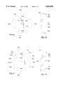
- FIG. 1 is a view, partly in section, of a two vessel adsorption system incorporating the novel valve system of the invention
- FIG. 2 is a plan view of the valve aperture disk used as both the first valve aperture disk and the second valve aperture disk of the adsorption system illustrated in FIG. 1;
- FIG. 4 is a plan view of the first valve passage disk used in the adsorption system illustrated in FIG. 1;
- FIG. 7 is a cross-sectional view of the second valve passage disk of FIG. 6, taken along the line 7--7;
- FIG. 8 is a plan view of a valve aperture disk useable as both the first valve aperture disk and the second valve aperture disk of a twelve vessel adsorption system;
- FIG. 9 is a plan view of the first valve passage disk of a two-valve disk system designed for use with the valve aperture disk of FIG. 8;
- FIG. 10 is a cross-sectional view of the valve passage disk of FIG. 9, taken along the line 10--10;
- FIG. 11 is a plan view of the second valve passage disk of a two-valve disk system designed for use with the valve aperture disk of FIG. 8;
- FIG. 12 is a cross-sectional view of the valve passage disk of FIG. 11, taken along the line 12--12;
- FIG. 13 is a plan view of a modified version of the valve passage disk of FIG. 11.
- the invention involves several aspects: (1) rotary valve systems that can be used in various industrial processes in which fluid is introduced into the system, fluid is withdrawn from the system and fluid is transferred from one point to another within the system; (2) multiple vessel adsorption systems that use these rotary valve systems; and (3) processes for fractionating fluids using the multiple vessel adsorption systems of the invention.
- fluid includes both gases and liquids. The process aspect of the invention will be described in detail as it applies to the fractionation of gases, although it applies equally well to liquid fractionations.
- valve systems of the invention are to direct a fluid feed to and to remove a waste fluid from the various adsorption vessels of a multiple vessel adsorption system and to provide outlet-to-outlet pressure equalization between an adsorption vessel that has just completed its adsorption step and one that has just completed its adsorbent regeneration step.
- the valve systems can, however, also control the flow of other fluid streams of the system, particularly the flow of the product stream from and the flow of purge fluid into the various adsorption vessels of the systems, or they can be used to control the flow of all streams of the adsorption systems, as described below.
- FIGS. 1-7 illustrated therein is an adsorption system comprising two adsorption vessels, A and B, valve assembly drive means C, first rotary valve assembly D and second rotary valve assembly E.
- the inlet ends of vessels A and B are connected to feed lines 2a and 2b, respectively, and the outlet ends of these vessels are connected to product outlet lines 4a and 4b, respectively.
- Valve assembly D comprises valve aperture disk 18, valve passage disk 20 and valve assembly cover 22.
- Valve assembly E comprises valve aperture disk 18, which is identical to valve aperture disk 18 of valve assembly D, valve passage disk 24 and valve assembly cover 26.
- each valve aperture disk 18, valve passage disk 20 and valve passage disk 24 are shown as circular in construction, although they may be shaped otherwise, for example polygonal, and these parts are preferably made from a durable material such as ceramic, which can be ground to a highly polished flat finish to enable the faces of the disks to form fluid-tight seals when pressed together.
- Each valve aperture disk 18 has highly polished flat circular engagement surface 28, smooth cylindrical sidewall 30, feed/product opening 32 and apertures 34a, 34b.
- the centers of apertures 34a and 34b are the same radial distance from the geometric center of surface 28.
- Opening 32 and apertures 34a, 34b are on the same diameter line through the geometric center of circular surface 28, and they extend completely through disks 18 in a direction perpendicular to surface 28 (FIG. 3).
- Apertures 34a, 34b are shown as being the same size in valve assemblies D and E, although the size of the apertures in valve assembly D can differ from the size of the apertures in valve assembly E.
- Apertures 34a, 34b of the same valve aperture disk 18 are the same size, however.
- Valve passage disk 20 which has a highly polished smooth circular engagement surface 36 and a smooth sidewall 38, has two arcuate passages or channels cut into surface 36, each of which has as its center of rotation the geometric center of circular surface 36 (FIGS. 4 and 5).
- feed distributor 40 which has a center circular portion 42 and an arcuate passage 44, and arcuate exhaust passage 46. Center circular portion 42 of feed distributor 40 extends deeper into disk 20 than does the remaining portions of distributor 40 (see FIG. 5).
- recess 54 Cut into the surface of disk 20 opposite surface 36 is recess 54 which has a square cross-section into which snugly fits first rotary valve engagement portion 12 of drive shaft 8. Recess 54 is circumscribed by the projection of circular portion 42 of feed distributor 40.
- sleeve 56 Fastened to the bottom of valve aperture disk 18 of valve assembly D in fluid-tight relationship therewith is sleeve 56 (FIG. 1), which has a hollow cylindrical portion that coincides with opening 32 of disk 18.
- Feed line 58 is attached to and extends through the sidewall of sleeve 56 to provide fluid communication between feed line 58 and the hollow interior of sleeve 56.
- Valve passage disk 24 which likewise has a highly polished smooth circular engagement surface 60 and a smooth sidewall 62, has several arcuate passages or channels cut into surface 60, each of which has as its center of rotation the geometric center of circular surface 60 (FIGS. 6 and 7). These include optional blind product collector 64, which has a center circular portion 66 and an arcuate passage 68; optional arcuate purge passage 70 and blind equalization passage 72, which has an arcuate portion 74 and end portions 76.
- Recess 78 has a square cross-section into which snugly fits second rotary valve engagement portion 16 of drive shaft 8.
- valve passage members 20 and 24 are designed for use in valve assemblies in which members 20 and 24 rotate in a clockwise direction, as viewed in FIGS. 4 and 6.
- valve assembly cover 22 of valve assembly D has a cylindrical sidewall 80 and is provided with exhaust line 82, which, in the illustrated embodiment, extends through sidewall 80.
- the inside diameter of sidewall 80 is somewhat greater than the outside diameters of valve disks 18 and 24.
- Positioned between the inside surface of sidewall 80 and disks 18 and 20 are resilient annular seal rings 84a and 84b, which form fluid-tight seals between the inside surface of sidewall 80 and the sidewalls of disks 18 and 20, respectively.
- These seal rings, together with disk sidewalls 30 and 38 and the inside wall of sidewall 80, form an annular channel around disks 18 and 20 through which fluids can pass.
- Line 82 and passage 46 communicate with the annular channel between seal rings 84a and 84b.
- valve assembly cover 26 of valve assembly E has a cylindrical sidewall 86 and is provided with purge gas supply line 88, which extends through sidewall 86.
- the inside diameter of sidewall 86 is somewhat greater than the outside diameters of valve disks 18 and 24.
- Positioned between the inside surface of sidewall 86 and disks 18 and 24 are resilient annular seal rings 90a and 90b, which form fluid-tight seals between the inside surface of sidewall 86 and sidewalls 30 and 62 of disks 18 and 24, respectively.
- These seal rings, together with sidewalls 30 and 62 and the inside wall of sidewall 86 form an annular channel around disks 18 and 24 through which fluids can pass.
- Line 88 and passage 70 communicate with the annular channel between seal rings 90a and 90b.
- Product line 92 is attached in fluid-tight relationship to the bottom surface of valve aperture disk 18 of valve assembly E in such a manner that fluid communication is established between line 92 and opening 32 of disk 18.
- valve aperture disk and the valve passage disk are pressed tightly together so that no leakage of fluid occurs between the engaged polished surfaces of the valve disks. This can be accomplished, for example, by means of a spring or by means of fluid pressure, as described in above-mentioned U.S. Pat. Nos. 5,268,021, 5,366,541 and RE 35099.
- upper cylindrical portion 10 of drive shaft 8 extends through the top wall of valve assembly cover 22 in non-binding relationship; square portion 12 of shaft 8 fits snugly into recess 54 of disk 20; lower cylindrical portion 14 of shaft 8 passes in non-binding relationship through disk 18 of valve assembly D, through sleeve 56 and through the top wall of valve assembly cover 26; and square portion 16 of shaft 8 fits snugly into recess 78 of disk 24.
- Annular seal ring 94 is fitted into the recessed part of center circular portion 42, and annular seal ring 96 is fitted into sleeve 56 below the point at which the lower edge of line 58 extends through sleeve 56.
- seal rings together with the cylindrical wall of lower portion 14, the wall of center circular opening 42 and the inner wall of sleeve 56 form a fluid-tight annular passage through which feed fluid can pass.
- This annular passage is in fluid communication with feed line 58 and distributor 40.
- feed lines 2a and 2b are connected in a fluid-tight relationship to the lower ends of openings 34a and 34b, respectively, of valve aperture disk 18 of valve assembly D and product outlet lines 4a and 4b are connected to the lower ends of openings 34a and 34b, respectively, of valve aperture disk 18 of valve assembly E.
- Each of these connections is fluid-tight.
- Motor 6 is connected to a source of electric power and has a control mechanism (not shown) for controlling the direction and speed of rotation of shaft 8. As drive shaft 8 rotates, it causes valve passage disks 20 and 24 to rotate at the same angular velocity to cycle adsorption vessels A and B through the various steps of the adsorption process.
- disks 18 and 20 of valve assembly D and disks 18 and 24 of valve assembly E are arranged so that the geometric centers of circular surfaces 28 (of each disk 18), of circular surface 36 and of circular surface 60 lie on the same line, and this line (centerline) serves as the center of rotation of valve passage disks 20 and 24.
- Motor 6 can impart continuous or stepwise rotation to valve disks 20 and 24 around the centerline.
- stepwise rotation the steps may coincide with the angular distance between the centers of adjacent openings in the ring arrays, which in the embodiment of FIGS. 1-7 is 180°; or it may be of some lesser angular extent such that the angular distance between the centers of adjacent openings of the ring arrays is an exact multiple of the angular extent of each step of rotation.
- arcuate passages 44 and 46 are in registration with the top ends of openings 34b and 34a, respectively, of valve disk 18 of valve assembly D, and arcuate passages 68 and 70 are in registration with the top ends of openings 34b and 34a, respectively, of valve disk 18 of valve assembly E.
- adsorption vessel B is in the adsorption stage and adsorption vessel A is in the adsorbent regeneration stage of the adsorption process.
- feed air which preferably has been prepurified to remove water vapor and carbon dioxide and filtered to remove solid impurities is fed at the desired pressure through line 58, the interior of sleeve 56, opening 32 of valve aperture disk 18 of valve assembly D, feed distributor 40, aperture 34b of disk 18 and line 2b, and into vessel B.
- oxygen is preferentially adsorbed by the adsorbent in the adsorber and nitrogen-enriched gas passes out of the bottom of vessel B through line 4b.
- the nitrogen-enriched gas passes through opening 34b of disk 18 of valve assembly E, arcuate product collector 64 and opening 32 of disk 18, exits the system through product line 92, and is sent to product storage or to a use application.
- the adsorbent in vessel A is undergoing regeneration. This is effected by depressurizing vessel A by venting gas contained in this vessel countercurrently (in the direction opposite the direction that feed gas passes through the adsorption vessel) from this vessel through line 2a.
- the vent gas passes through opening 34a of disk 18 of valve assembly D and arcuate passage 46 and enters the annular space defined by outer surfaces 30 and 38 of disks 18 and 20, respectively, the inside surface of sidewall 80 of cover 22 and seal rings 84a and 84b.
- the vented gas then exits the system via line 82 and is vented to the atmosphere, or is otherwise used or disposed of.
- Adsorbent regeneration may be carried out by simply evacuating vessel A, or it may be assisted by purging vessel A with a gas that is lean in the adsorbed component, for example the nitrogen enriched product gas produced in vessel B during the adsorption process.
- a purge step is to be included in the process, the selected purge gas is introduced into the system through line 88 and it enters the annular space defined by the inside surface of sidewall 86, surfaces 30 and 62 of disks 18 and 24, respectively, and seal rings 90a and 90b.
- the purge gas passes through passage 70, aperture 34a of disk 18 and line 4a, and flows countercurrently through vessel A. As it does so it flushes adsorbed oxygen from vessel A.
- the purged exhaust, and possibly some purge gas, pass out of the system 10 through line 82.
- drive shaft 8 continues to rotate in the selected direction, for example clockwise as viewed in FIGS. 4 and 6.
- the velocity of rotation is set such that the trailing edges of passages 44 and 46 will pass out of registration with openings 34b and 34a, respectively, of disk 18 of valve assembly D, at the exact time when the adsorption front reaches the desired end point of the adsorption step.
- the trailing edges of passages 68 and 70 will pass out of registration with openings 34b and 34a, respectively of disk 18 of valve assembly E.
- equalization passage 72 As rotation of valve disks 20 and 24 continues, end portions 76 of equalization passage 72 will come into registration with openings 34a and 34b of disk 18 of valve assembly E. At this point gas will flow from vessel B, through line 2b, opening 34b of disk 18 of valve assembly E, equalization passage 72, opening 34a of disk 18, line 2a and into vessel A. No gas is transferred through the passages of disk 20 during this period. Thus, gas from the outlet end of vessel B will flow into the outlet end of vessel A, thereby effecting outlet-to-outlet pressure equalization. Accordingly, the gas from vessel B which is most enriched in nitrogen will enter the product end of vessel A, thus making the process highly efficient.
- the bed equalization step can be allowed to continue until the pressure in the two vessels reaches equilibrium or for any shorter period of time.
- the time extent of the equalization step is determined by the velocity of rotation and by the width of end portions 76 of equalization passage 72. End portions 76 can be as narrow or as wide as desired, within the limits set by the distance between the trailing and leading edges of passages 68 and 70.
- FIGS. 8-12 illustrate the construction of a valve aperture disk and valve passage disks that are intended for use in the multiple vessel embodiment of the invention.
- Valve aperture disk 118 and valve passage disks 120 and 124 are likewise shown as circular in construction, although they may have other shapes.
- valve aperture disk 118 and valve passage disks 120 and 124 are preferably made of a durable material such as ceramic, which can be ground to a highly polished flat finish to enable the faces of the disks to form fluid-tight seals when pressed together.
- Valve aperture disk 118 which is designed for use with either valve passage disk 120 or valve passage disk 124 (described below) has a highly polished flat circular engagement surface 128; a smooth cylindrical sidewall 130 (like sidewall 30 of disk 18, FIG. 3); a feed inlet/product outlet opening 132; and an array of twelve equally spaced apertures 134. Apertures 134 lie in the same ring array, i.e. their centers are all the same radial distance from the geometric center of surface 128. Opening 132 and apertures 134 extend completely through disk 118 in a direction perpendicular to surface 128 (as in valve aperture disk 18, FIG. 3). All apertures on a single disk 118 are the same size, but apertures of a disk 118 intended for use with valve passage disk 120 may be the same size as, or larger or smaller than the apertures of a disk 118 intended for use with valve passage disk 124
- valve passage disk 120 which has a highly polished smooth engagement surface 136, and a smooth sidewall 138, has several arcuate passages or channels, each of which has as its center of rotation the geometric center of surface 136.
- Disk 120 has feed distributor 140 with recessed center portion 142 and diametrically opposed arcuate passages 144a and 144b, and diametrically opposed arcuate exhaust passages 146a and 146b. Recessed center portion 142 of feed distributor 140 extends deeper into disk 120 than does the remaining portions of distributor 140 (see FIG. 10).
- Recess 154 has a square cross-section into which snugly fits first rotary valve engagement portion 12 of drive shaft 8, to enable disk 120 to be rotated over surface 128 of valve member 118 (FIG. 1).
- valve passage disk 124 which has a highly polished smooth circular engagement surface 160 and a smooth sidewall 162, has several arcuate passages or channels cut into surface 160, each of which has as its center of rotation the geometric center of circular surface 160.
- These include optional product collector 164 which has a pair of diametrically opposed arcuate product passages 168a and 168b; optional arcuate purge passages 170a and 170b; and diametrically opposed blind equalization passages 172a and 172b, which have end portions 176a and 176b, respectively.
- Product collector 164 and purge passages 170a and 170b are constructed substantially the same as feed distributor 140 and exhaust passages 146a and 146b, respectively.
- blind recess 178 Cut into the surface of disk 124 opposite surface 160 is blind recess 178, which has a square cross-section into which snugly fits second rotary valve engagement portion 16 of drive shaft 8, to enable disk 124 to be rotated over surface 128 of valve member 118 (see FIG. 1).
- valve aperture disk 118 and valve passage disk 120 are designed to replace valve aperture disk 18 and valve passage disk 20, respectively, of valve assembly D, and a valve aperture disk 118 and valve passage disk 124 are designed to replace valve aperture disk 18 and valve passage disk 24, respectively of valve assembly E in the valve assembly of FIG. 1, and the valve assemblies with disks 118, 120 and 124 will perform in the same manner as the assembly with disks 18, 20 and 24, except that it will operate a twelve adsorber system instead of a two adsorber system. Since valve passage disk 120 has two diametrically opposed feed and exhaust passages and valve passage disk 124 has two diametrically opposed product, purge and equalization passages, each adsorption vessel will undergo a complete adsorption cycle every half rotation of the valve passage disks.
- valve passage disks 120 and 124 there will be 24 production stages; accordingly, the adsorption process conducted with disks 118, 120 and 124 will produce a much more continuous flow of product than is produced in the two vessel system illustrated in FIG. 1.
- the twelve aperture embodiment of FIGS. 8-12 has another advantage over the two aperture embodiment of FIGS. 2-7. Since the various gas streams simultaneously pass through diametrically opposite sides of the valve assemblies when the embodiment of FIGS. 8-12 is used, pressure will be distributed equally on both sides of the valve assembly, and the valve assembly will experience less stress than would be experienced with the FIGS. 2-7 embodiment.
- Valve passage disk 224 illustrated in FIG. 13, is similar to disk 124, shown in FIG. 11, but differs from disk 124 in two respects. One difference is that end portions 276a, 276b of equalization passages 272a, 272b are significantly wider than end portions 176a, 176b of equalization passages 172a, 172b. Since this will result in the transfer of more partially fractionated process stream from the outlet end of the vessels being depressurized to the outlet end of the receiving adsorption vessels, this embodiment provides more complete equalization.
- a second difference between the construction of disks 224 and 124 is the extended size of arcuate product passages 268a, 268b.
- ports 268a, 268b each have a portion 269a, 269b which extends clockwise beyond the leading edge of passages 144a, 144b (indicated by dotted lines 271a, 271b, respectively) when disk 124 is used in valve assembly D and disk 224 is used in valve assembly E and these disks are aligned so that the straight portions of feed distributor 140 and product collector 264 coincide.
- Lines 271a and 271b are then in the same radial vector plane from the geometric center of disk 224 as the leading edges (when disks 120 and 224 are rotated clockwise) of arcuate passages 144a and 144b, respectively, of disk 120.
- the extended portions serve as backfill sections and provide for the flow of product gas, for example from line 92 (FIG. 1), countercurrently into the adsorption vessels that have been partially pressurized in the just-completed pressure equalization step, to further pressurize these vessels to near operating adsorption pressure.
- Optional arcuate purge passages 270a and 270b are substantially the same as purge passages 170a and 170b, respectively, of FIG. 11. Either or both of the modifications illustrated in FIG. 13 can be incorporated into any of the valve passage disks described herein.
- the adsorption vessels used in the system of the invention may be straight elongate vessels or they may be U-shaped or concentric so that, for example, their inlet ends and outlet ends are adjacent or somewhat adjacent each other.
- Concentric bed vessels have an inner cylindrical adsorbent-packed compartment surrounded by an outer annular adsorbent-packed compartment, the two compartments being of equal cross-sectional area and separated by a cylindrical wall which is sealed to one end of the vessels but does not extend to the other end of the vessels.
- Each compartment has an opening at the sealed end of the vessel, and fluid that is introduced into one compartment through its opening will pass axially through that compartment in one direction and axially through the other compartment in the opposite direction and leave the other compartment through its opening.
- a particular advantage of concentric bed adsorption vessels is the potential for heat exchange between the two beds at their feed/outlet ends.
- valve passage disks can be interchanged.
- the part designated as feed distributor 140 can function as the exhaust collector, and the parts designated as exhaust passages 146a and 146b can function as feed passages.
- the part designated as product collector 164 can function as the purge distributor and purge passages 170a and 170b can function as product passages.
- flow of the product stream produced in the adsorption process does not have to be controlled by valve assembly E. Nor it is necessary that the purge fluid (if the process includes a purge step) pass through valve assembly E.
- the product stream can pass directly from the outlet ends of the adsorption vessels to storage, and purging can be accomplished by inserting an orifice in the product flow line. Both of these alternatives are described in U.S. Pat. Nos. 5,268,021, 5,366,541 and RE 35099, discussed above.
- Vacuum regeneration can be conducted by itself or it can be conducted with the aid of a purge stream, whether or not the purge stream passes through the valve assemblies of the invention.
- valve assemblies used in the system contains the valve members illustrated in FIGS. 2-7 and the adsorption vessels are packed with carbon molecular sieve.
- This valve assembly arrangement provides an adsorption cycle with an outlet-to-outlet equalization step.
- the valve system is operated at a rate such that the rotatable valve passage disks complete a revolution in about 120 seconds.
- air which has been prepurified to remove water vapor and carbon dioxide is compressed to a pressure of about 7.5 bara (bar absolute) and fed into the feed inlet of the system at a temperature of 20° C., 168 Nliters per hour of nitrogen-enriched gas having a purity of 99% will be produced.
- valve passage disks 20 and 24 The system illustrated in FIG. 1 is used in this example, but with the positions of valve passage disks 20 and 24 reversed, so that the system will provide only inlet-to-inlet pressure equalization.
- the valve system is again operated at a rate such that the rotatable valve passage disks complete a revolution in about 120 seconds.
- air which has been prepurified to remove water vapor and carbon dioxide is compressed to a pressure of about 7.5 bara (bar absolute) and fed into the feed inlet of the system at a temperature of 20° C., 141 Nliters per hour of nitrogen-enriched gas having a purity of 99% will be produced.
- Example 1 shows that when the valve assembly of the invention is used (Example 1), the nitrogen product flow rate will be about 26% greater than when a valve assembly which provides only inlet-to-inlet pressure equalization is used.
- valve assemblies D and E can be operated by drive means different from that illustrated in FIG. 1.
- the drive motor can be positioned between valve assemblies D and E and arranged such that a drive shaft extends from each end of the drive motor, or separate motors can be used to drive valve assemblies D and E.
Abstract
Description
Claims (32)
Priority Applications (7)
| Application Number | Priority Date | Filing Date | Title |
|---|---|---|---|
| US08/787,183 US5820656A (en) | 1997-01-21 | 1997-01-21 | Process and apparatus for gas separation |
| EP98300077A EP0853967A3 (en) | 1997-01-21 | 1998-01-07 | Valve apparatus for gas separation and adsorption system |
| AU52094/98A AU735294B2 (en) | 1997-01-21 | 1998-01-16 | Process and apparatus for gas separation |
| NZ32959198A NZ329591A (en) | 1997-01-21 | 1998-01-16 | Valve system for separation of gases by pressure swing adsorption, comprising rotatable apertured surfaces |
| CN 98105810 CN1201708A (en) | 1997-01-21 | 1998-01-19 | Process and apparatus for gas separation |
| PL32437498A PL324374A1 (en) | 1997-01-21 | 1998-01-20 | Gas separating method and apparatus |
| CA 2227483 CA2227483C (en) | 1997-01-21 | 1998-01-20 | Process and apparatus for gas separation |
Applications Claiming Priority (1)
| Application Number | Priority Date | Filing Date | Title |
|---|---|---|---|
| US08/787,183 US5820656A (en) | 1997-01-21 | 1997-01-21 | Process and apparatus for gas separation |
Publications (1)
| Publication Number | Publication Date |
|---|---|
| US5820656A true US5820656A (en) | 1998-10-13 |
Family
ID=25140660
Family Applications (1)
| Application Number | Title | Priority Date | Filing Date |
|---|---|---|---|
| US08/787,183 Expired - Fee Related US5820656A (en) | 1997-01-21 | 1997-01-21 | Process and apparatus for gas separation |
Country Status (1)
| Country | Link |
|---|---|
| US (1) | US5820656A (en) |
Cited By (27)
| Publication number | Priority date | Publication date | Assignee | Title |
|---|---|---|---|---|
| US6143056A (en) * | 1998-11-19 | 2000-11-07 | Praxair Technology, Inc. | Rotary valve for two bed vacuum pressure swing absorption system |
| US6253778B1 (en) | 1998-11-19 | 2001-07-03 | Praxair Technology, Inc. | Rotary valve |
| US6514319B2 (en) * | 1999-12-09 | 2003-02-04 | Questair Technologies Inc. | Life support oxygen concentrator |
| US6651658B1 (en) | 2000-08-03 | 2003-11-25 | Sequal Technologies, Inc. | Portable oxygen concentration system and method of using the same |
| US6691702B2 (en) | 2000-08-03 | 2004-02-17 | Sequal Technologies, Inc. | Portable oxygen concentration system and method of using the same |
| US6712087B2 (en) * | 1999-08-10 | 2004-03-30 | Sequal Technologies, Inc. | Rotary valve assembly for pressure swing adsorption system |
| USRE38493E1 (en) * | 1996-04-24 | 2004-04-13 | Questair Technologies Inc. | Flow regulated pressure swing adsorption system |
| US20040094216A1 (en) * | 2002-11-15 | 2004-05-20 | Wagner Glenn Paul | Rotary sequencing valve with flexible port plate |
| US20040197616A1 (en) * | 2003-04-01 | 2004-10-07 | Edlund David J. | Oxidant-enriched fuel cell system |
| US20050056149A1 (en) * | 2003-09-17 | 2005-03-17 | Metso Automation Usa Inc. | System and method for treating fluid using a multi-port valve assembly |
| US20050098033A1 (en) * | 2003-11-12 | 2005-05-12 | Kiran Mallavarapu | Control of a hydrogen purifying pressure swing adsorption unit in fuel processor module for hydrogen generation |
| US20050098034A1 (en) * | 2003-11-12 | 2005-05-12 | Gittleman Craig S. | Hydrogen purification process using pressure swing adsorption for fuel cell applications |
| US20050132881A1 (en) * | 2003-12-23 | 2005-06-23 | Baksh Mohamed S.A. | Indexing rotary dual valve for pressure swing adsorption systems |
| US20050183572A1 (en) * | 1999-12-09 | 2005-08-25 | Questair Technologies Inc. | Life support oxygen concentrator |
| US20060130651A1 (en) * | 2004-12-22 | 2006-06-22 | Bizjak Travis A | Systems and methods for regulating heating assembly operation through pressure swing adsorption purge control |
| US20060130650A1 (en) * | 2004-12-20 | 2006-06-22 | Givens James A | Temperature-based breakthrough detection and pressure swing adsorption systems and fuel processing systems including the same |
| US20070028971A1 (en) * | 2005-08-05 | 2007-02-08 | Wagner Glenn P | Rotary valve with internal leak control system |
| US20070289445A1 (en) * | 2006-06-15 | 2007-12-20 | Mei Hua | Compact and efficient pressure swing oxygen concentrator |
| US20080148935A1 (en) * | 2004-12-20 | 2008-06-26 | Idatech, Llc | Temperature-based breakthrough detection and pressure swing adsorption systems and fuel processing systems including the same |
| US20090107332A1 (en) * | 2007-10-29 | 2009-04-30 | Air Products And Chemicals, Inc. | Rotary Valve |
| US20090151560A1 (en) * | 2007-12-12 | 2009-06-18 | Idatech, Llc | Systems and methods for supplying auxiliary fuel streams during intermittent byproduct discharge from pressure swing adsorption assemblies |
| US20090151249A1 (en) * | 2007-12-12 | 2009-06-18 | Adams Patton M | Systems and methods for supplying auxiliary fuel streams during intermittent byproduct discharge from pressure swing adsorption assemblies |
| US20100166645A1 (en) * | 2006-10-27 | 2010-07-01 | Rajeev Agnihotri | Compact pressure swing reformer |
| US20110017063A1 (en) * | 2009-07-22 | 2011-01-27 | Van Brunt Nicholas P | Apparatus for separating oxygen from ambient air |
| US20110197890A1 (en) * | 2005-02-09 | 2011-08-18 | Vbox, Incorporated | Ambulatory oxygen concentrator |
| DE102010049487B3 (en) * | 2010-10-27 | 2012-01-26 | Mann + Hummel Protec Gmbh | Device for drying fluid and method for operating the same |
| US10201775B2 (en) * | 2015-07-13 | 2019-02-12 | Nuvera Fuel Cells, LLC | Regulating flow of pressure swing adsorbers |
Citations (17)
| Publication number | Priority date | Publication date | Assignee | Title |
|---|---|---|---|---|
| US2706532A (en) * | 1953-03-26 | 1955-04-19 | Adsorption Res Corp | Fluid treating apparatus |
| US2751032A (en) * | 1954-11-09 | 1956-06-19 | Adsorption Res Corp | Fluid treating apparatus |
| US4038054A (en) * | 1972-03-25 | 1977-07-26 | Graeff Roderich Wilhelm | Adsorption apparatus |
| EP0107179A2 (en) * | 1982-10-21 | 1984-05-02 | Preussag AG Kunststoffe u. Armaturen | Device for splitting a gas mixture by selective adsorption of a fraction of the mixture |
| US4469494A (en) * | 1983-01-31 | 1984-09-04 | Kinetics Technology International Corporation | Disc operated gas purification system |
| US4925464A (en) * | 1988-11-17 | 1990-05-15 | Ryder International Corporation | Fluid flow switching valve assembly and system |
| US5114441A (en) * | 1990-11-02 | 1992-05-19 | Ryder International Corporation | Oxygen concentrator system and valve structure |
| EP0512534A1 (en) * | 1991-05-09 | 1992-11-11 | Mitsubishi Jukogyo Kabushiki Kaisha | Gas separating system and gas recovery system |
| US5176722A (en) * | 1990-06-19 | 1993-01-05 | The Boc Group, Inc. | Pressure swing adsorption method for separating gaseous mixtures |
| US5256174A (en) * | 1991-08-01 | 1993-10-26 | Mitsubishi Jukogyo Kabushiki Kaisha | Gas separator system |
| US5268021A (en) * | 1989-11-20 | 1993-12-07 | Dynotec Corporation | Fluid fractionator |
| US5441559A (en) * | 1992-04-13 | 1995-08-15 | L'air Liquide, Societe Anonyme Pour L'etude Et L'exploitation Des Procedes Georges Claude | Rotatable device for the separation by adsorption of at least one constituent of a gaseous mixture |
| USRE35099E (en) * | 1989-11-20 | 1995-11-28 | Sequal Technologies, Inc. | Fluid fractionator |
| US5584322A (en) * | 1993-06-01 | 1996-12-17 | Ppv Verwaltungs Ag | Rotary slide valve |
| US5593478A (en) * | 1994-09-28 | 1997-01-14 | Sequal Technologies, Inc. | Fluid fractionator |
| US5593480A (en) * | 1993-01-15 | 1997-01-14 | Ppv Verwaltungs Ag | Apparatus for the oxygen enrichment of air |
| US5681376A (en) * | 1995-11-07 | 1997-10-28 | Calgon Carbon Corporation | Rotating flow distributor assembly for use in continuously distributing decontamination and regeneration fluid flow |
-
1997
- 1997-01-21 US US08/787,183 patent/US5820656A/en not_active Expired - Fee Related
Patent Citations (19)
| Publication number | Priority date | Publication date | Assignee | Title |
|---|---|---|---|---|
| US2706532A (en) * | 1953-03-26 | 1955-04-19 | Adsorption Res Corp | Fluid treating apparatus |
| US2751032A (en) * | 1954-11-09 | 1956-06-19 | Adsorption Res Corp | Fluid treating apparatus |
| US4038054A (en) * | 1972-03-25 | 1977-07-26 | Graeff Roderich Wilhelm | Adsorption apparatus |
| EP0107179A2 (en) * | 1982-10-21 | 1984-05-02 | Preussag AG Kunststoffe u. Armaturen | Device for splitting a gas mixture by selective adsorption of a fraction of the mixture |
| US4469494A (en) * | 1983-01-31 | 1984-09-04 | Kinetics Technology International Corporation | Disc operated gas purification system |
| US4925464A (en) * | 1988-11-17 | 1990-05-15 | Ryder International Corporation | Fluid flow switching valve assembly and system |
| US5366541A (en) * | 1989-11-20 | 1994-11-22 | Dynotec Corporation | Fluid fractionator |
| US5268021A (en) * | 1989-11-20 | 1993-12-07 | Dynotec Corporation | Fluid fractionator |
| USRE35099E (en) * | 1989-11-20 | 1995-11-28 | Sequal Technologies, Inc. | Fluid fractionator |
| US5176722A (en) * | 1990-06-19 | 1993-01-05 | The Boc Group, Inc. | Pressure swing adsorption method for separating gaseous mixtures |
| US5114441A (en) * | 1990-11-02 | 1992-05-19 | Ryder International Corporation | Oxygen concentrator system and valve structure |
| EP0512534A1 (en) * | 1991-05-09 | 1992-11-11 | Mitsubishi Jukogyo Kabushiki Kaisha | Gas separating system and gas recovery system |
| US5248325A (en) * | 1991-05-09 | 1993-09-28 | Mitsubishi Jukogyo Kabushiki Kaisha | Gas separating system and gas recovery system |
| US5256174A (en) * | 1991-08-01 | 1993-10-26 | Mitsubishi Jukogyo Kabushiki Kaisha | Gas separator system |
| US5441559A (en) * | 1992-04-13 | 1995-08-15 | L'air Liquide, Societe Anonyme Pour L'etude Et L'exploitation Des Procedes Georges Claude | Rotatable device for the separation by adsorption of at least one constituent of a gaseous mixture |
| US5593480A (en) * | 1993-01-15 | 1997-01-14 | Ppv Verwaltungs Ag | Apparatus for the oxygen enrichment of air |
| US5584322A (en) * | 1993-06-01 | 1996-12-17 | Ppv Verwaltungs Ag | Rotary slide valve |
| US5593478A (en) * | 1994-09-28 | 1997-01-14 | Sequal Technologies, Inc. | Fluid fractionator |
| US5681376A (en) * | 1995-11-07 | 1997-10-28 | Calgon Carbon Corporation | Rotating flow distributor assembly for use in continuously distributing decontamination and regeneration fluid flow |
Cited By (59)
| Publication number | Priority date | Publication date | Assignee | Title |
|---|---|---|---|---|
| USRE40006E1 (en) * | 1996-04-24 | 2008-01-22 | Questair Technologies Inc. | Flow regulated pressure swing adsorption system |
| USRE38493E1 (en) * | 1996-04-24 | 2004-04-13 | Questair Technologies Inc. | Flow regulated pressure swing adsorption system |
| US6253778B1 (en) | 1998-11-19 | 2001-07-03 | Praxair Technology, Inc. | Rotary valve |
| US6143056A (en) * | 1998-11-19 | 2000-11-07 | Praxair Technology, Inc. | Rotary valve for two bed vacuum pressure swing absorption system |
| US6712087B2 (en) * | 1999-08-10 | 2004-03-30 | Sequal Technologies, Inc. | Rotary valve assembly for pressure swing adsorption system |
| US20050183572A1 (en) * | 1999-12-09 | 2005-08-25 | Questair Technologies Inc. | Life support oxygen concentrator |
| US6514319B2 (en) * | 1999-12-09 | 2003-02-04 | Questair Technologies Inc. | Life support oxygen concentrator |
| US20030196550A1 (en) * | 1999-12-09 | 2003-10-23 | Questair Technologies Inc. | Life support oxygen concentrator |
| US7250073B2 (en) | 1999-12-09 | 2007-07-31 | Questair Technologies, Inc. | Life support oxygen concentrator |
| US6691702B2 (en) | 2000-08-03 | 2004-02-17 | Sequal Technologies, Inc. | Portable oxygen concentration system and method of using the same |
| US6651658B1 (en) | 2000-08-03 | 2003-11-25 | Sequal Technologies, Inc. | Portable oxygen concentration system and method of using the same |
| US6889710B2 (en) | 2002-11-15 | 2005-05-10 | Air Products And Chemicals, Inc. | Rotary sequencing valve with flexible port plate |
| US20040094216A1 (en) * | 2002-11-15 | 2004-05-20 | Wagner Glenn Paul | Rotary sequencing valve with flexible port plate |
| US20040197616A1 (en) * | 2003-04-01 | 2004-10-07 | Edlund David J. | Oxidant-enriched fuel cell system |
| US7445662B2 (en) | 2003-09-17 | 2008-11-04 | Metso Automation Usa, Inc. | System and method for treating fluid using a multi-port valve assembly |
| US6936091B2 (en) * | 2003-09-17 | 2005-08-30 | Metso Automation Usa, Inc. | System and method for treating fluid using a multi-port valve assembly |
| US20060011061A1 (en) * | 2003-09-17 | 2006-01-19 | Metso Automation Usa Inc. | System and method for treating fluid using a multi-port valve assembly |
| US20050056149A1 (en) * | 2003-09-17 | 2005-03-17 | Metso Automation Usa Inc. | System and method for treating fluid using a multi-port valve assembly |
| US7011693B2 (en) * | 2003-11-12 | 2006-03-14 | General Motors Corporation | Control of a hydrogen purifying pressure swing adsorption unit in fuel processor module for hydrogen generation |
| US20050098034A1 (en) * | 2003-11-12 | 2005-05-12 | Gittleman Craig S. | Hydrogen purification process using pressure swing adsorption for fuel cell applications |
| US20050098033A1 (en) * | 2003-11-12 | 2005-05-12 | Kiran Mallavarapu | Control of a hydrogen purifying pressure swing adsorption unit in fuel processor module for hydrogen generation |
| US20050132881A1 (en) * | 2003-12-23 | 2005-06-23 | Baksh Mohamed S.A. | Indexing rotary dual valve for pressure swing adsorption systems |
| US7276107B2 (en) | 2003-12-23 | 2007-10-02 | Praxair Technology, Inc. | Indexing rotary dual valve for pressure swing adsorption systems |
| US20080148935A1 (en) * | 2004-12-20 | 2008-06-26 | Idatech, Llc | Temperature-based breakthrough detection and pressure swing adsorption systems and fuel processing systems including the same |
| US20060130650A1 (en) * | 2004-12-20 | 2006-06-22 | Givens James A | Temperature-based breakthrough detection and pressure swing adsorption systems and fuel processing systems including the same |
| US7833311B2 (en) | 2004-12-20 | 2010-11-16 | Idatech, Llc | Temperature-based breakthrough detection and pressure swing adsorption systems and fuel processing systems including the same |
| US7393382B2 (en) | 2004-12-20 | 2008-07-01 | Idatech Llc | Temperature-based breakthrough detection and pressure swing adsorption systems and fuel processing systems including the same |
| US7833326B2 (en) | 2004-12-22 | 2010-11-16 | Idatech, Llc | Systems and methods for regulating heating assembly operation through pressure swing adsorption purge control |
| US8038771B2 (en) | 2004-12-22 | 2011-10-18 | Idatech, Llc | Systems and methods for regulating heating assembly operation through pressure swing adsorption purge control |
| US20080302011A1 (en) * | 2004-12-22 | 2008-12-11 | Idatech, Llc | Systems and methods for regulating heating assembly operation through pressure swing adsorption purge control |
| US20060130651A1 (en) * | 2004-12-22 | 2006-06-22 | Bizjak Travis A | Systems and methods for regulating heating assembly operation through pressure swing adsorption purge control |
| US7399342B2 (en) | 2004-12-22 | 2008-07-15 | Idatech, Llc | Systems and methods for regulating heating assembly operation through pressure swing adsorption purge control |
| US10702669B2 (en) | 2005-02-09 | 2020-07-07 | Vbox, Incorporated | Removable cartridge for oxygen concentrator |
| US10357628B2 (en) | 2005-02-09 | 2019-07-23 | 3B Medical Manufacturing Llc | Removable cartridge for oxygen concentrator |
| US20110197890A1 (en) * | 2005-02-09 | 2011-08-18 | Vbox, Incorporated | Ambulatory oxygen concentrator |
| US11389614B2 (en) | 2005-02-09 | 2022-07-19 | Vbox, Incorporated | Removable cartridge for oxygen concentrator |
| US7500490B2 (en) | 2005-08-05 | 2009-03-10 | Air Products And Chemicals, Inc. | Rotary valve with internal leak control system |
| US20070028971A1 (en) * | 2005-08-05 | 2007-02-08 | Wagner Glenn P | Rotary valve with internal leak control system |
| EP1752204A1 (en) * | 2005-08-05 | 2007-02-14 | Air Products and Chemicals, Inc. | Rotary valve with internal leak control system |
| WO2007144764A2 (en) * | 2006-06-15 | 2007-12-21 | Kedl International Limited | Compact and efficient pressure swing oxygen concentrator |
| US20070289445A1 (en) * | 2006-06-15 | 2007-12-20 | Mei Hua | Compact and efficient pressure swing oxygen concentrator |
| WO2007144764A3 (en) * | 2006-06-15 | 2008-02-21 | Kedl Internat Ltd | Compact and efficient pressure swing oxygen concentrator |
| US8551444B2 (en) * | 2006-10-27 | 2013-10-08 | Air Products And Chemicals, Inc. | Compact pressure swing reformer |
| US9687803B2 (en) | 2006-10-27 | 2017-06-27 | Air Products And Chemicals, Inc. | Compact pressure swing reformer |
| US20100166645A1 (en) * | 2006-10-27 | 2010-07-01 | Rajeev Agnihotri | Compact pressure swing reformer |
| US20090107332A1 (en) * | 2007-10-29 | 2009-04-30 | Air Products And Chemicals, Inc. | Rotary Valve |
| US7819948B2 (en) | 2007-10-29 | 2010-10-26 | Air Products And Chemicals, Inc. | Rotary valve |
| US20090151249A1 (en) * | 2007-12-12 | 2009-06-18 | Adams Patton M | Systems and methods for supplying auxiliary fuel streams during intermittent byproduct discharge from pressure swing adsorption assemblies |
| US8070841B2 (en) | 2007-12-12 | 2011-12-06 | Idatech, Llc | Systems and methods for supplying auxiliary fuel streams during intermittent byproduct discharge from pressure swing adsorption assemblies |
| US7837765B2 (en) | 2007-12-12 | 2010-11-23 | Idatech, Llc | Systems and methods for supplying auxiliary fuel streams during intermittent byproduct discharge from pressure swing adsorption assemblies |
| US20090151560A1 (en) * | 2007-12-12 | 2009-06-18 | Idatech, Llc | Systems and methods for supplying auxiliary fuel streams during intermittent byproduct discharge from pressure swing adsorption assemblies |
| US8617294B2 (en) | 2007-12-12 | 2013-12-31 | Dcns Sa | Systems and methods for supplying auxiliary fuel streams during intermittent byproduct discharge from pressure swing adsorption assemblies |
| US10335570B2 (en) | 2009-07-22 | 2019-07-02 | 3B Medical Inc. | Method of separating and distributing oxygen |
| US8695600B2 (en) | 2009-07-22 | 2014-04-15 | Vbox, Incorporated | Method of separating and distributing oxygen |
| US8597408B2 (en) | 2009-07-22 | 2013-12-03 | Vbox, Incorporated | Apparatus for separating oxygen from ambient air |
| US8394178B2 (en) | 2009-07-22 | 2013-03-12 | Vbox, Incorporated | Apparatus for separating oxygen from ambient air |
| US20110017063A1 (en) * | 2009-07-22 | 2011-01-27 | Van Brunt Nicholas P | Apparatus for separating oxygen from ambient air |
| DE102010049487B3 (en) * | 2010-10-27 | 2012-01-26 | Mann + Hummel Protec Gmbh | Device for drying fluid and method for operating the same |
| US10201775B2 (en) * | 2015-07-13 | 2019-02-12 | Nuvera Fuel Cells, LLC | Regulating flow of pressure swing adsorbers |
Similar Documents
| Publication | Publication Date | Title |
|---|---|---|
| US5891217A (en) | Process and apparatus for gas separation | |
| US5820656A (en) | Process and apparatus for gas separation | |
| US5807423A (en) | Process and apparatus for gas separation | |
| US5814130A (en) | Process and apparatus for gas separation | |
| US5814131A (en) | Process and apparatus for gas separation | |
| AU735294B2 (en) | Process and apparatus for gas separation | |
| US4469494A (en) | Disc operated gas purification system | |
| US9101872B2 (en) | Pressure swing adsorption system with indexed rotatable multi-port valves | |
| US6712087B2 (en) | Rotary valve assembly for pressure swing adsorption system | |
| AU638898B2 (en) | Gas separator system | |
| CA2214916C (en) | Process and apparatus for gas separation | |
| EP0681860B1 (en) | Continuous pressure difference driven adsorption process | |
| US5268021A (en) | Fluid fractionator | |
| US7276107B2 (en) | Indexing rotary dual valve for pressure swing adsorption systems | |
| US5827358A (en) | Rapid cycle pressure swing adsorption oxygen concentration method and apparatus | |
| JPS6344599B2 (en) | ||
| JPH11192410A (en) | Oxygen concentrating device | |
| EP0627953B1 (en) | fluid fractionator | |
| ZA200704991B (en) | Pressure swing adsorption system with indexed rotatable multi-port valves | |
| JP3643075B2 (en) | Improved fluid separation device | |
| WO2022237573A1 (en) | Pressure swing adsorption device and rotary valve thereof | |
| BRPI0702800B1 (en) | ADSORPTION SYSTEM BY PRESSURE MODULATION WITH ROTATING VALVES WITH MULTIPLE STAGED OPENINGS, AND METHOD FOR RECOVERING A COMPONENT LESS INTENSELY LIABLE TO ADSORPTION FROM A FEED GAS MIXTURE |
Legal Events
| Date | Code | Title | Description |
|---|---|---|---|
| AS | Assignment |
Owner name: BOC GROUP, INC., THE, NEW JERSEY Free format text: ASSIGNMENT OF ASSIGNORS INTEREST;ASSIGNORS:LEMCOFF, NORBERTO O.;FRONZONI, MARIO A.;GARRETT, MICHAEL E.;AND OTHERS;REEL/FRAME:008860/0417;SIGNING DATES FROM 19970728 TO 19971001 |
|
| FEPP | Fee payment procedure |
Free format text: PAYOR NUMBER ASSIGNED (ORIGINAL EVENT CODE: ASPN); ENTITY STATUS OF PATENT OWNER: LARGE ENTITY |
|
| FPAY | Fee payment |
Year of fee payment: 4 |
|
| REMI | Maintenance fee reminder mailed | ||
| AS | Assignment |
Owner name: SILICON VALLEY BANK, CALIFORNIA Free format text: SECURITY AGREEMENT;ASSIGNOR:SEQUAL TECHNOLOGIES INC.;REEL/FRAME:013599/0832 Effective date: 20021203 |
|
| AS | Assignment |
Owner name: SEQUAL TECHNOLOGIES, INC., CALIFORNIA Free format text: RELEASE BY SECURED PARTY;ASSIGNOR:SILICON VALLEY BANK;REEL/FRAME:014220/0958 Effective date: 20030612 |
|
| AS | Assignment |
Owner name: SEQUAL TECHNOLOGIES INC., CALIFORNIA Free format text: RELEASE;ASSIGNOR:SILICON VALLEY BANK;REEL/FRAME:014277/0041 Effective date: 20030708 |
|
| FPAY | Fee payment |
Year of fee payment: 8 |
|
| AS | Assignment |
Owner name: SILICON VALLEY BANK, CALIFORNIA Free format text: SECURITY AGREEMENT;ASSIGNOR:SEQUAL TECHNOLOGIES, INC.;REEL/FRAME:019331/0819 Effective date: 20070521 |
|
| REMI | Maintenance fee reminder mailed | ||
| LAPS | Lapse for failure to pay maintenance fees | ||
| STCH | Information on status: patent discontinuation |
Free format text: PATENT EXPIRED DUE TO NONPAYMENT OF MAINTENANCE FEES UNDER 37 CFR 1.362 |
|
| FP | Lapsed due to failure to pay maintenance fee |
Effective date: 20101013 |
|
| AS | Assignment |
Owner name: SEQUAL TECHNOLOGIES, INC., CALIFORNIA Free format text: RELEASE;ASSIGNOR:SILICON VALLEY BANK;REEL/FRAME:025651/0107 Effective date: 20101222 Owner name: SEQUAL TECHNOLOGIES, INC., CALIFORNIA Free format text: RELEASE;ASSIGNOR:SILICON VALLEY BANK;REEL/FRAME:025650/0410 Effective date: 20101222 |