EP1479918B1 - Gebläsemodul für einen Kraftfahrzeugsitz - Google Patents
Gebläsemodul für einen Kraftfahrzeugsitz Download PDFInfo
- Publication number
- EP1479918B1 EP1479918B1 EP04001472A EP04001472A EP1479918B1 EP 1479918 B1 EP1479918 B1 EP 1479918B1 EP 04001472 A EP04001472 A EP 04001472A EP 04001472 A EP04001472 A EP 04001472A EP 1479918 B1 EP1479918 B1 EP 1479918B1
- Authority
- EP
- European Patent Office
- Prior art keywords
- motor vehicle
- vehicle seat
- heating
- seat
- blower
- Prior art date
- Legal status (The legal status is an assumption and is not a legal conclusion. Google has not performed a legal analysis and makes no representation as to the accuracy of the status listed.)
- Expired - Lifetime
Links
Images


Classifications
-
- B—PERFORMING OPERATIONS; TRANSPORTING
- B60—VEHICLES IN GENERAL
- B60N—SEATS SPECIALLY ADAPTED FOR VEHICLES; VEHICLE PASSENGER ACCOMMODATION NOT OTHERWISE PROVIDED FOR
- B60N2/00—Seats specially adapted for vehicles; Arrangement or mounting of seats in vehicles
- B60N2/56—Heating or ventilating devices
-
- D—TEXTILES; PAPER
- D04—BRAIDING; LACE-MAKING; KNITTING; TRIMMINGS; NON-WOVEN FABRICS
- D04B—KNITTING
- D04B21/00—Warp knitting processes for the production of fabrics or articles not dependent on the use of particular machines; Fabrics or articles defined by such processes
- D04B21/14—Fabrics characterised by the incorporation by knitting, in one or more thread, fleece, or fabric layers, of reinforcing, binding, or decorative threads; Fabrics incorporating small auxiliary elements, e.g. for decorative purposes
- D04B21/16—Fabrics characterised by the incorporation by knitting, in one or more thread, fleece, or fabric layers, of reinforcing, binding, or decorative threads; Fabrics incorporating small auxiliary elements, e.g. for decorative purposes incorporating synthetic threads
-
- F—MECHANICAL ENGINEERING; LIGHTING; HEATING; WEAPONS; BLASTING
- F04—POSITIVE - DISPLACEMENT MACHINES FOR LIQUIDS; PUMPS FOR LIQUIDS OR ELASTIC FLUIDS
- F04D—NON-POSITIVE-DISPLACEMENT PUMPS
- F04D17/00—Radial-flow pumps, e.g. centrifugal pumps; Helico-centrifugal pumps
- F04D17/08—Centrifugal pumps
- F04D17/16—Centrifugal pumps for displacing without appreciable compression
-
- F—MECHANICAL ENGINEERING; LIGHTING; HEATING; WEAPONS; BLASTING
- F04—POSITIVE - DISPLACEMENT MACHINES FOR LIQUIDS; PUMPS FOR LIQUIDS OR ELASTIC FLUIDS
- F04D—NON-POSITIVE-DISPLACEMENT PUMPS
- F04D29/00—Details, component parts, or accessories
- F04D29/58—Cooling; Heating; Diminishing heat transfer
- F04D29/582—Cooling; Heating; Diminishing heat transfer specially adapted for elastic fluid pumps
-
- D—TEXTILES; PAPER
- D10—INDEXING SCHEME ASSOCIATED WITH SUBLASSES OF SECTION D, RELATING TO TEXTILES
- D10B—INDEXING SCHEME ASSOCIATED WITH SUBLASSES OF SECTION D, RELATING TO TEXTILES
- D10B2403/00—Details of fabric structure established in the fabric forming process
- D10B2403/02—Cross-sectional features
- D10B2403/021—Lofty fabric with equidistantly spaced front and back plies, e.g. spacer fabrics
-
- D—TEXTILES; PAPER
- D10—INDEXING SCHEME ASSOCIATED WITH SUBLASSES OF SECTION D, RELATING TO TEXTILES
- D10B—INDEXING SCHEME ASSOCIATED WITH SUBLASSES OF SECTION D, RELATING TO TEXTILES
- D10B2505/00—Industrial
- D10B2505/08—Upholstery, mattresses
Definitions
- the invention relates to a motor vehicle seat and fan module for a such motor vehicle seat.
- the fan module according to claim 1 is adapted to the above needs by: it has a design which has a low overall height, due to the radial fan and the other components arranged in a plane.
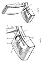
- the motor vehicle seat has in a conventional form a seat cushion part 1 and a backrest 2 on.
- Both the seat cushion part 1, as well as the backrest 2 consist essentially from a support body 3 particularly advantageous from rigid foam, for example Polyurethane, but also as spring core seat, in which the required mounting rails and frames are integrated.
- a support body 3 particularly advantageous from rigid foam, for example Polyurethane, but also as spring core seat, in which the required mounting rails and frames are integrated.
- a knitted fabric 4 glued on the outer cover 5, for example Velor or leather lies.
- rigid foam air flow channels 6 are provided, which in a chamber 7 open and are open on their entire length to the knitted fabric 4 out.
- the knitted fabric 4 has a thickness of about 1 cm and consists of individual honeycomb Cells each about 1 sq. Cm. The cells are interconnected via fibers connected, which can not be fully compressed under load, so that in the chamber 7 injected air over the entire surface of the knitted fabric 4 distributed and can emerge evenly at all points of the reference 5.
- the in FIG. 2 knitted fabric 4 shown in more detail is e.g. from a honeycomb Nylon braid having a base layer 4a and a cover layer 4b and a plurality spacers 4c between these layers 4a, 4b.
- Base and cover layer 4a, 4b have at their edges interconnected cells of about 60 qmm. They are formed by a thread formed from about 20 individual threads, the one Diameter of about 0.05 mm. At least at the corners are the Cells of the opposing layers 4a, 4b by spacers 4c the same material joined together and in the unloaded state on one Kept at a distance of about 1 cm.
- the spacers 4c are preferably arcuate designed to give the knitted fabric 4 a predetermined elasticity.
- Desirable is an elasticity or compliance that is at an initial Surface pressure of 0 to about 20 g / qcm practically does not lead to any deformation and then at an increasing surface pressure up to approximately 100 g / qcm linear approach of the two layers 4a, 4b leads, but also at maximum Wing loading still an air exchange between the two Layers allows.
- the blown by the fan module 8 air as evenly as possible in the areas remote from the air flow channels 6 areas distributed, it must be ensured that the flow resistance per surface of the surface reference 5 is significantly larger than that of the knit 4.
- a surface reference made of leather are in the leather a variety of through holes at a mutual distance of about 4 mm and a diameter of about 1 mm provided.
- both the seat cushion part 1, and the back part 2 is provided with a fan module 8, each in a chamber. 9 or recess in the lower part of the seat cushion part 1 and the rear part of the Backrest 2 are provided.
- the chamber 9 is closed by a cover, not shown, which has the necessary recesses for the fan module 8 and the outside flush with the seat contour, and only one or more, preferably has laterally arranged air intake openings, which have corresponding Channels lead to the fan module 8.
- the seat cushion part 1 is in the corner to the backrest 2 with a box-shaped Outlet 16 provided to optionally additionally leak air at this point to let.
- the vent 16 is connected on the input side to the air flow channel 6 and on the output side with a grid 17 completed.
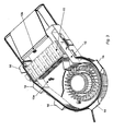
- the fan module 8 is shown in FIG. 3 shown in more detail. It consists of a flat Box of about 3 cm height in the side by side a radial fan 10, a preferably composed of PTC elements heating register 11, one on a circuit board constructed electrical control 12 and each a temperature sensor 13a and 13b are arranged. On the outer periphery of the box is a number of fastening tabs 14 are provided, which serve the box with corresponding counterparts to connect in the support body 3.
- the temperature sensors 13a and 13b respectively are each provided in the cold or hot air tract and with the electronic control 12 connected.
- the electronic control 12 is still not closer shown lines with motor vehicle electrical system, the radial fan 10, and corresponding preferably mounted in the seating area controls connected about the heating intensity and the fan speed independently of each other can be adjusted.
- the electronic control 12 works with the following functional profile:
- the radial fan 10 runs over approximately 5 sec slowly up to the set nominal speed, around the seat still in the seat Allow cold air to escape slowly.
- the desired heating power is regulated delivered to the heater, wherein the control is designed such that thereon It is taken into account that the generator is not overloaded. It will So less heating power may be taken than requested by the user.
- the speed of the radial fan 10 is either independently adjustable or at least partially coupled with the heat output, with higher heat outputs also automatically the speed of the radial fan 10 is increased.
- the radial fan 10 runs first after switching on about 3 minutes on suction and then on blowing operation.
- the radial fan can therefore be operated in two directions, which can be activated by voltage reversal are.
- the air intake can also be connected to the compressor of the compressor for summer operation Motor vehicle be connected.
- the radial fan 10 sucks the air from an opening immediately below it in the box, pushes it along the PTC heating elements Channels in the Ausblas Consumer and a lid, not shown, of the box in the air flow channels 6, which are arranged in the rigid foam of the support body 3 are.
Landscapes
- Engineering & Computer Science (AREA)
- Mechanical Engineering (AREA)
- General Engineering & Computer Science (AREA)
- Aviation & Aerospace Engineering (AREA)
- Transportation (AREA)
- Physics & Mathematics (AREA)
- Thermal Sciences (AREA)
- Textile Engineering (AREA)
- Chair Legs, Seat Parts, And Backrests (AREA)
- Air-Conditioning For Vehicles (AREA)
- Mattresses And Other Support Structures For Chairs And Beds (AREA)
Description
Claims (1)
- Gebläsemodul (8) zum Einsatz in einem Kraftfahrzeugsitz, der eine Luftansaugöffnung,
wenigstens eine Ausblasöffnung,
ein Radialgebläse (10), welches eingangsseitig mit der Luftansaugöffnung in Verbindung steht,
ein elektrische Heizwiderstände aufweisendes Heizregister (11) und
eine elektronische Steuerung (12) aufweist, wobei dieser Gebläsemodul (8) dadurch gekennzeichnet ist, dass im Ansaugtrakt und im Ausblastrakt jeweils ein Temperatursensor (13a, 13b) angeordnet ist, die als Ist-Wertgeber, mit der elektronischen Steuerung (12) verbunden sind, und
dass diese Einheiten baulich in einer Ebene nebeneinander angeordnet sind.
Priority Applications (1)
| Application Number | Priority Date | Filing Date | Title |
|---|---|---|---|
| EP04001472A EP1479918B1 (de) | 2003-04-02 | 2003-04-02 | Gebläsemodul für einen Kraftfahrzeugsitz |
Applications Claiming Priority (2)
| Application Number | Priority Date | Filing Date | Title |
|---|---|---|---|
| EP04001472A EP1479918B1 (de) | 2003-04-02 | 2003-04-02 | Gebläsemodul für einen Kraftfahrzeugsitz |
| EP03007403A EP1464533B2 (de) | 2003-04-02 | 2003-04-02 | Kraftfahrzeugsitz und Gebläsemodul für einen solchen Kraftfahrzeugsitz |
Related Parent Applications (1)
| Application Number | Title | Priority Date | Filing Date |
|---|---|---|---|
| EP03007403A Division EP1464533B2 (de) | 2003-04-02 | 2003-04-02 | Kraftfahrzeugsitz und Gebläsemodul für einen solchen Kraftfahrzeugsitz |
Publications (2)
| Publication Number | Publication Date |
|---|---|
| EP1479918A1 EP1479918A1 (de) | 2004-11-24 |
| EP1479918B1 true EP1479918B1 (de) | 2005-10-12 |
Family
ID=32842723
Family Applications (2)
| Application Number | Title | Priority Date | Filing Date |
|---|---|---|---|
| EP04001472A Expired - Lifetime EP1479918B1 (de) | 2003-04-02 | 2003-04-02 | Gebläsemodul für einen Kraftfahrzeugsitz |
| EP03007403A Expired - Lifetime EP1464533B2 (de) | 2003-04-02 | 2003-04-02 | Kraftfahrzeugsitz und Gebläsemodul für einen solchen Kraftfahrzeugsitz |
Family Applications After (1)
| Application Number | Title | Priority Date | Filing Date |
|---|---|---|---|
| EP03007403A Expired - Lifetime EP1464533B2 (de) | 2003-04-02 | 2003-04-02 | Kraftfahrzeugsitz und Gebläsemodul für einen solchen Kraftfahrzeugsitz |
Country Status (7)
| Country | Link |
|---|---|
| US (1) | US20040195870A1 (de) |
| EP (2) | EP1479918B1 (de) |
| JP (1) | JP3878617B2 (de) |
| KR (1) | KR100554640B1 (de) |
| CN (1) | CN1533934A (de) |
| DE (2) | DE50301359D1 (de) |
| ES (2) | ES2264743T5 (de) |
Families Citing this family (153)
| Publication number | Priority date | Publication date | Assignee | Title |
|---|---|---|---|---|
| US6119463A (en) | 1998-05-12 | 2000-09-19 | Amerigon | Thermoelectric heat exchanger |
| US6893086B2 (en) | 2002-07-03 | 2005-05-17 | W.E.T. Automotive Systems Ltd. | Automotive vehicle seat insert |
| US6857697B2 (en) | 2002-08-29 | 2005-02-22 | W.E.T. Automotive Systems Ag | Automotive vehicle seating comfort system |
| DE10259621B4 (de) | 2002-12-18 | 2005-12-01 | W.E.T. Automotive Systems Ag | Fahrzeugsitz und zugehörige Klimatisierungseinrichtung |
| DE10259648B4 (de) | 2002-12-18 | 2006-01-26 | W.E.T. Automotive Systems Ag | Klimatisierter Sitz und Klimatisierungseinrichtung für einen ventilierten Sitz |
| US7274007B2 (en) | 2003-09-25 | 2007-09-25 | W.E.T. Automotive Systems Ltd. | Control system for operating automotive vehicle components |
| US7356912B2 (en) | 2003-09-25 | 2008-04-15 | W.E.T. Automotive Systems, Ltd. | Method for ventilating a seat |
| US7425034B2 (en) | 2003-10-17 | 2008-09-16 | W.E.T. Automotive Systems Ag | Automotive vehicle seat having a comfort system |
| US7370911B2 (en) | 2003-10-17 | 2008-05-13 | W.E.T. Automotive Systems, Ag | Automotive vehicle seat insert |
| US7461892B2 (en) | 2003-12-01 | 2008-12-09 | W.E.T. Automotive Systems, A.C. | Valve layer for a seat |
| US7114771B2 (en) * | 2004-05-25 | 2006-10-03 | Amerigon, Inc. | Climate controlled seat |
| US7828050B2 (en) * | 2004-09-02 | 2010-11-09 | Honda Motor Co., Ltd. | Vehicle seat air-conditioner and vehicle temperature controller |
| DE102004052076B4 (de) * | 2004-10-26 | 2007-10-11 | W.L. Gore & Associates Gmbh | Fahrzeugsitz |
| US7587901B2 (en) | 2004-12-20 | 2009-09-15 | Amerigon Incorporated | Control system for thermal module in vehicle |
| WO2006102969A1 (en) * | 2005-03-30 | 2006-10-05 | Intier Automotive Seating Systems Gmbh | Automobile vehicle passenger seat and process for producing a vehicle passenger seat |
| DE102005018445B3 (de) | 2005-04-20 | 2006-06-29 | W.E.T. Automotive Systems Ag | Klimatisierungseinrichtung für einen Sitz |
| DE102005026541A1 (de) * | 2005-06-08 | 2006-12-14 | Bayerische Motoren Werke Ag | Fahrzeugsitz mit einer Luftführungsschicht unter einem Oberflächenbezug |
| WO2007012436A1 (de) * | 2005-07-27 | 2007-02-01 | Daimlerchrysler Ag | Kraftfahrzeugsitz mit einer luftversorgungseinrichtung |
| DE202005012394U1 (de) | 2005-08-06 | 2005-12-08 | Microhellix Systems Gmbh | Elektrisches Heizmodul zur Luftstromerwärmung, insbesondere in Fahrzeugen |
| US7478869B2 (en) | 2005-08-19 | 2009-01-20 | W.E.T. Automotive Systems, Ag | Automotive vehicle seat insert |
| US8539624B2 (en) | 2006-05-31 | 2013-09-24 | Gentherm Incorporated | Structure based fluid distribution system |
| DE102006035541A1 (de) * | 2006-07-27 | 2008-01-31 | Sitech Sitztechnik Gmbh | Klimatisierter Sitz |
| US20080087316A1 (en) | 2006-10-12 | 2008-04-17 | Masa Inaba | Thermoelectric device with internal sensor |
| WO2008057962A2 (en) * | 2006-11-01 | 2008-05-15 | Amerigon Incorporated | Chair with air conditioning device |
| EP1918138B1 (de) * | 2006-11-06 | 2009-05-20 | Eberspächer catem GmbH & Co. KG | Gebläsemodul für einen Fahrzeugsitz und Kraftfahrzeugsitz mit Geräuschisolierung |
| DE102007006058B4 (de) | 2007-02-02 | 2009-11-26 | Microhellix Systems Gmbh | Elektrisches Heizmodul zur Luftstromerwärmung, insbesondere zur Heizung und Belüftung von Sitzen |
| US7877827B2 (en) | 2007-09-10 | 2011-02-01 | Amerigon Incorporated | Operational control schemes for ventilated seat or bed assemblies |
| US20090082927A1 (en) * | 2007-09-25 | 2009-03-26 | W.E.T. Automotive Systems Ag | Integrated seat conditioning and multi-component control module |
| US8979620B2 (en) * | 2007-11-27 | 2015-03-17 | W.E.T. Automotive Systems Ag | Seat conditioning hood apparatus and method |
| WO2009076123A2 (en) | 2007-12-10 | 2009-06-18 | W.E.T. Automotive Systems Ag | Improved seat conditioning module and method |
| EP2402209B1 (de) * | 2008-01-24 | 2013-06-05 | Eberspächer catem GmbH & Co. KG | Elektrische Zusatzheizung für ein Kraftfahrzeug |
| EP2082919B2 (de) * | 2008-01-24 | 2018-08-15 | Eberspächer catem GmbH & Co. KG | Elektrische Zusatzheizung für ein Kraftfahrzeug |
| KR101779870B1 (ko) | 2008-02-01 | 2017-10-10 | 젠썸 인코포레이티드 | 열전 소자용 응결 센서 및 습도 센서 |
| DE102008017965B4 (de) | 2008-04-08 | 2011-06-01 | W.E.T. Automotive Systems Ag | Belüftungseinrichtung |
| JP5997899B2 (ja) | 2008-07-18 | 2016-09-28 | ジェンサーム インコーポレイテッドGentherm Incorporated | 空調されるベッドアセンブリ |
| EP2199166A1 (de) | 2008-12-19 | 2010-06-23 | Safe-Tec ApS | Bremssteuersystem für ein abgeschlepptes Fahrzeug und Verfahren zur Kalibrierung des Bremssteuersystems |
| DE102009058996B4 (de) * | 2008-12-21 | 2012-12-06 | W.E.T. Automotive Systems Ag | Belüftungseinrichtung |
| DE202010002050U1 (de) | 2009-02-18 | 2010-07-15 | W.E.T. Automotive Systems Ag | Klimatisierungseinrichtung für Fahrzeugsitze |
| KR101712100B1 (ko) * | 2010-01-12 | 2017-03-03 | 삼성전자 주식회사 | 냉각장치 및 이를 구비하는 표시장치 |
| DE102010033310B4 (de) | 2010-08-04 | 2012-06-14 | Ingo Schehr | Elektrisches Heizmodul mit PTC-Element zum elektrischen Erwärmen eines Luftstroms |
| DE202010011016U1 (de) | 2010-08-04 | 2011-10-10 | Ingo Schehr | Elektrisches Heizmodul mit PTC-Element zum elektrischen Erwärmen eines Luftstroms |
| KR101219967B1 (ko) * | 2010-09-28 | 2013-01-08 | 현대자동차주식회사 | Ptc히터를 이용한 차량용 난방장치 및 그 방법 |
| US9121414B2 (en) | 2010-11-05 | 2015-09-01 | Gentherm Incorporated | Low-profile blowers and methods |
| DE102012001819A1 (de) * | 2011-03-30 | 2012-10-04 | Ebm-Papst St. Georgen Gmbh & Co. Kg | Belüftungsvorrichtung |
| DE202011100054U1 (de) | 2011-04-30 | 2011-06-15 | MicroHellix GmbH, 53505 | Elektrisches Heizmodul zur Luftstromwärmung |
| DE102012014678A1 (de) | 2011-08-19 | 2013-02-21 | W.E.T. Automotive Systems Ag | Heizeinrichtung |
| WO2013052823A1 (en) | 2011-10-07 | 2013-04-11 | Gentherm Incorporated | Thermoelectric device controls and methods |
| DE102011121978B4 (de) | 2011-11-17 | 2023-03-16 | Gentherm Gmbh | Heiz- oder Temperier-Einrichtung |
| KR101345849B1 (ko) * | 2011-11-22 | 2013-12-30 | 갑을오토텍(주) | 시트용 통풍장치 |
| DE102012020516A1 (de) | 2011-12-09 | 2013-06-13 | W.E.T. Automotive Systems Ag | Temperier-Einrichtung für eine elektrochemische Spannungsquelle |
| KR101356157B1 (ko) * | 2011-12-09 | 2014-01-29 | 현대자동차주식회사 | 차량의 시트 |
| US9975394B2 (en) * | 2011-12-23 | 2018-05-22 | Faurecia Automotive Seating, Llc | Airflow management system for vehicle seat |
| DE102011121980A1 (de) | 2011-12-26 | 2013-06-27 | W.E.T. Automotive Systems Ag | Luftfördereinrichtung |
| US9989267B2 (en) | 2012-02-10 | 2018-06-05 | Gentherm Incorporated | Moisture abatement in heating operation of climate controlled systems |
| KR101367620B1 (ko) * | 2012-07-27 | 2014-03-12 | (주)케이엠앤아이 | 차량용 통풍 시트 |
| US9168852B2 (en) | 2012-12-03 | 2015-10-27 | Ford Global Technologies, Llc | Climate comfort seat assembly |
| US8727374B1 (en) | 2013-01-24 | 2014-05-20 | Ford Global Technologies, Llc | Vehicle seatback with side airbag deployment |
| US9016783B2 (en) | 2013-01-24 | 2015-04-28 | Ford Global Technologies, Llc | Thin seat flex rest composite cushion extension |
| US9016784B2 (en) | 2013-01-24 | 2015-04-28 | Ford Global Technologies, Llc | Thin seat leg support system and suspension |
| US9399418B2 (en) | 2013-01-24 | 2016-07-26 | Ford Global Technologies, Llc | Independent cushion extension and thigh support |
| US9061616B2 (en) | 2013-01-24 | 2015-06-23 | Ford Global Technologies, Llc | Articulating headrest assembly |
| US9096157B2 (en) | 2013-01-24 | 2015-08-04 | Ford Global Technologies, Llc | Seating assembly with air distribution system |
| US9415713B2 (en) | 2013-01-24 | 2016-08-16 | Ford Global Technologies, Llc | Flexible seatback system |
| US9409504B2 (en) | 2013-01-24 | 2016-08-09 | Ford Global Technologies, Llc | Flexible seatback system |
| US9126508B2 (en) | 2013-01-24 | 2015-09-08 | Ford Global Technologies, Llc | Upper seatback pivot system |
| US9902293B2 (en) | 2013-01-24 | 2018-02-27 | Ford Global Technologies, Llc | Independent cushion extension with optimized leg-splay angle |
| US9216677B2 (en) | 2013-01-24 | 2015-12-22 | Ford Global Technologies, Llc | Quick-connect trim carrier attachment |
| US9126504B2 (en) | 2013-01-24 | 2015-09-08 | Ford Global Technologies, Llc | Integrated thin flex composite headrest assembly |
| US9193284B2 (en) | 2013-06-11 | 2015-11-24 | Ford Global Technologies, Llc | Articulating cushion bolster for ingress/egress |
| US9527418B2 (en) | 2013-09-12 | 2016-12-27 | Ford Global Technologies, Llc | Semi rigid push/pull vented envelope system |
| US8905431B1 (en) | 2013-09-24 | 2014-12-09 | Ford Global Technologies, Llc | Side airbag assembly for a vehicle seat |
| US9187019B2 (en) | 2013-10-17 | 2015-11-17 | Ford Global Technologies, Llc | Thigh support for customer accommodation seat |
| US9505322B2 (en) | 2013-10-25 | 2016-11-29 | Ford Global Technologies, Llc | Manual lumbar pump assembly |
| US9662962B2 (en) | 2013-11-05 | 2017-05-30 | Gentherm Incorporated | Vehicle headliner assembly for zonal comfort |
| US9315130B2 (en) | 2013-11-11 | 2016-04-19 | Ford Global Technologies, Llc | Articulating head restraint |
| US9566884B2 (en) | 2013-11-11 | 2017-02-14 | Ford Global Technologies, Llc | Powered head restraint electrical connector |
| DE112014005563T5 (de) | 2013-12-05 | 2016-11-24 | Gentherm Incorporated | Systeme und Verfahren für klimatisierte Sitze |
| US9365143B2 (en) | 2013-12-12 | 2016-06-14 | Ford Global Technologies, Llc | Rear seat modular cushion |
| US9315131B2 (en) | 2014-01-23 | 2016-04-19 | Ford Global Technologies, Llc | Suspension seat back and cushion system having an inner suspension panel |
| KR102252584B1 (ko) | 2014-02-14 | 2021-05-14 | 젠썸 인코포레이티드 | 전도식 대류식 기온 제어 조립체 |
| US9649963B2 (en) | 2014-03-04 | 2017-05-16 | Ford Global Technologies, Pllc | Trim and foam assembly for a vehicle seat |
| US9527419B2 (en) | 2014-03-31 | 2016-12-27 | Ford Global Technologies, Llc | Vehicle seating assembly with manual cushion tilt |
| US9421894B2 (en) | 2014-04-02 | 2016-08-23 | Ford Global Technologies, Llc | Vehicle seating assembly with manual independent thigh supports |
| US9302643B2 (en) | 2014-04-02 | 2016-04-05 | Ford Global Technologies, Llc | Vehicle seating assembly with side airbag deployment |
| US9694741B2 (en) | 2014-08-25 | 2017-07-04 | Ford Global Technologies, Llc | Ambient functional lighting of a seat |
| US10471874B2 (en) | 2014-09-02 | 2019-11-12 | Ford Global Technologies, Llc | Massage bladder matrix |
| US9789790B2 (en) | 2014-10-03 | 2017-10-17 | Ford Global Technologies, Llc | Tuned flexible support member and flexible suspension features for comfort carriers |
| US9333882B2 (en) | 2014-10-03 | 2016-05-10 | Ford Global Technologies, Llc | Manual upper seatback support |
| US9776533B2 (en) | 2014-10-03 | 2017-10-03 | Ford Global Technologies, Llc | Torsion bar upper seatback support assembly |
| JP6355845B2 (ja) * | 2014-10-28 | 2018-07-11 | ジェンサーム オートモーティブ システムズ チャイナリミテッド | ランバースペーサ |
| US9771003B2 (en) | 2014-10-29 | 2017-09-26 | Ford Global Technologies, Llc | Apparatus for customizing a vehicle seat for an occupant |
| US9340131B1 (en) | 2014-11-06 | 2016-05-17 | Ford Global Technologies, Llc | Head restraint with a multi-cell bladder assembly |
| US9517777B2 (en) | 2014-11-06 | 2016-12-13 | Ford Global Technologies, Llc | Lane departure feedback system |
| US11033058B2 (en) | 2014-11-14 | 2021-06-15 | Gentherm Incorporated | Heating and cooling technologies |
| US11639816B2 (en) | 2014-11-14 | 2023-05-02 | Gentherm Incorporated | Heating and cooling technologies including temperature regulating pad wrap and technologies with liquid system |
| US11857004B2 (en) | 2014-11-14 | 2024-01-02 | Gentherm Incorporated | Heating and cooling technologies |
| US10065570B2 (en) | 2014-12-10 | 2018-09-04 | Ford Global Technologies, Llc | Electronic device holder for a vehicle seat |
| US9593642B2 (en) | 2014-12-19 | 2017-03-14 | Ford Global Technologies, Llc | Composite cam carrier |
| US9663000B2 (en) | 2015-01-16 | 2017-05-30 | Ford Global Technologies, Llc | Vehicle seat configured to improve access |
| US9707877B2 (en) | 2015-01-20 | 2017-07-18 | Ford Global Technologies, Llc | Independent thigh extension and support trim carrier |
| US9365142B1 (en) | 2015-01-20 | 2016-06-14 | Ford Global Technologies, Llc | Manual independent thigh extensions |
| US9566930B2 (en) | 2015-03-02 | 2017-02-14 | Ford Global Technologies, Llc | Vehicle seat assembly with side-impact airbag deployment mechanism |
| KR101729226B1 (ko) * | 2015-04-17 | 2017-05-04 | 씨제이포디플렉스 주식회사 | 특수효과 의자 및 이를 포함하는 시스템 |
| US9802535B2 (en) | 2015-04-27 | 2017-10-31 | Ford Global Technologies, Llc | Seat having ambient lighting |
| CN104970610A (zh) * | 2015-06-12 | 2015-10-14 | 海宁海派皮业有限公司 | 一种智能沙发椅 |
| US10046682B2 (en) | 2015-08-03 | 2018-08-14 | Ford Global Technologies, Llc | Back cushion module for a vehicle seating assembly |
| US9718387B2 (en) | 2015-08-03 | 2017-08-01 | Ford Global Technologies, Llc | Seat cushion module for a vehicle seating assembly |
| US9688174B2 (en) | 2015-08-07 | 2017-06-27 | Ford Global Technologies, Llc | Multi-cell seat cushion assembly |
| US9573528B1 (en) | 2015-08-25 | 2017-02-21 | Ford Global Technologies, Llc | Integrated seatback storage |
| US9616776B1 (en) | 2015-11-16 | 2017-04-11 | Ford Global Technologies, Llc | Integrated power thigh extender |
| US9809131B2 (en) | 2015-12-04 | 2017-11-07 | Ford Global Technologies, Llc | Anthropomorphic pivotable upper seatback support |
| US9931999B2 (en) | 2015-12-17 | 2018-04-03 | Ford Global Technologies, Llc | Back panel lower clip anchorage features for dynamic events |
| US10093214B2 (en) | 2016-01-14 | 2018-10-09 | Ford Global Technologies, Llc | Mechanical manual leg tilt |
| US9914421B2 (en) | 2016-01-15 | 2018-03-13 | Ford Global Technologies, Llc | Seatback flexible slip plane joint for side air bag deployment |
| US10052990B2 (en) | 2016-01-25 | 2018-08-21 | Ford Global Technologies, Llc | Extended seatback module head restraint attachment |
| US9756408B2 (en) | 2016-01-25 | 2017-09-05 | Ford Global Technologies, Llc | Integrated sound system |
| US10035442B2 (en) | 2016-01-25 | 2018-07-31 | Ford Global Technologies, Llc | Adjustable upper seatback module |
| US9776543B2 (en) | 2016-01-25 | 2017-10-03 | Ford Global Technologies, Llc | Integrated independent thigh supports |
| CN108602457A (zh) * | 2016-01-28 | 2018-09-28 | 标致雪铁龙汽车股份有限公司 | 座椅通风风机上的隔音装置 |
| KR200485005Y1 (ko) * | 2016-01-28 | 2017-11-20 | 이미영 | 차량용 통풍시트 |
| US10647230B2 (en) * | 2016-02-23 | 2020-05-12 | Denso Corporation | Seat air conditioner |
| US10240607B2 (en) | 2016-02-26 | 2019-03-26 | Kongsberg Automotive, Inc. | Blower assembly for a vehicle seat |
| US10286818B2 (en) | 2016-03-16 | 2019-05-14 | Ford Global Technologies, Llc | Dual suspension seating assembly |
| US10046681B2 (en) | 2016-04-12 | 2018-08-14 | Ford Global Technologies, Llc | Articulating mechanical thigh extension composite trim payout linkage system |
| US9849817B2 (en) | 2016-03-16 | 2017-12-26 | Ford Global Technologies, Llc | Composite seat structure |
| US9994135B2 (en) | 2016-03-30 | 2018-06-12 | Ford Global Technologies, Llc | Independent cushion thigh support |
| US10220737B2 (en) | 2016-04-01 | 2019-03-05 | Ford Global Technologies, Llc | Kinematic back panel |
| US9889773B2 (en) | 2016-04-04 | 2018-02-13 | Ford Global Technologies, Llc | Anthropomorphic upper seatback |
| US10081279B2 (en) | 2016-04-12 | 2018-09-25 | Ford Global Technologies, Llc | Articulating thigh extension trim tensioning slider mechanism |
| US9802512B1 (en) | 2016-04-12 | 2017-10-31 | Ford Global Technologies, Llc | Torsion spring bushing |
| DE102016004639A1 (de) * | 2016-04-16 | 2017-10-19 | Daimler Ag | Heizmodul für eine Kopfstütze eines Fahrzeugsitzes |
| US9845029B1 (en) | 2016-06-06 | 2017-12-19 | Ford Global Technologies, Llc | Passive conformal seat with hybrid air/liquid cells |
| US9834166B1 (en) | 2016-06-07 | 2017-12-05 | Ford Global Technologies, Llc | Side airbag energy management system |
| US9849856B1 (en) | 2016-06-07 | 2017-12-26 | Ford Global Technologies, Llc | Side airbag energy management system |
| US10377279B2 (en) | 2016-06-09 | 2019-08-13 | Ford Global Technologies, Llc | Integrated decking arm support feature |
| US10166895B2 (en) | 2016-06-09 | 2019-01-01 | Ford Global Technologies, Llc | Seatback comfort carrier |
| US10286824B2 (en) | 2016-08-24 | 2019-05-14 | Ford Global Technologies, Llc | Spreader plate load distribution |
| US10279714B2 (en) | 2016-08-26 | 2019-05-07 | Ford Global Technologies, Llc | Seating assembly with climate control features |
| US10239431B2 (en) | 2016-09-02 | 2019-03-26 | Ford Global Technologies, Llc | Cross-tube attachment hook features for modular assembly and support |
| US10391910B2 (en) | 2016-09-02 | 2019-08-27 | Ford Global Technologies, Llc | Modular assembly cross-tube attachment tab designs and functions |
| US9914378B1 (en) | 2016-12-16 | 2018-03-13 | Ford Global Technologies, Llc | Decorative and functional upper seatback closeout assembly |
| US10596936B2 (en) | 2017-05-04 | 2020-03-24 | Ford Global Technologies, Llc | Self-retaining elastic strap for vent blower attachment to a back carrier |
| US10479243B2 (en) | 2017-12-05 | 2019-11-19 | Ford Global Technologies, Llc | Air channel thermocomfort foam pad |
| DE102017011525A1 (de) * | 2017-12-13 | 2019-06-13 | Gentherm Gmbh | Gebläsemodul zum Bereitstellen einer temperierten Luftströmung |
| US11223004B2 (en) | 2018-07-30 | 2022-01-11 | Gentherm Incorporated | Thermoelectric device having a polymeric coating |
| DE102018212999A1 (de) * | 2018-08-03 | 2020-02-06 | Mahle Lnternational Gmbh | Kindersitzanordnung und ein Verfahren zum Steuern oder Regeln der Kindersitzanordnung |
| DE102018218494A1 (de) * | 2018-10-29 | 2020-04-30 | Volkswagen Aktiengesellschaft | Fahrzeugsitz für ein Kraftfahrzeug |
| CN121230238A (zh) | 2018-11-30 | 2025-12-30 | 金瑟姆股份公司 | 热电调节系统和方法 |
| US11152557B2 (en) | 2019-02-20 | 2021-10-19 | Gentherm Incorporated | Thermoelectric module with integrated printed circuit board |
| KR102524032B1 (ko) | 2021-03-05 | 2023-04-21 | (주)대성파인텍 | 블로워 장치 |
| US12611909B2 (en) | 2021-03-18 | 2026-04-28 | Gentherm Incorporated | Preconditioning surfaces using intelligent thermal effectors |
| US12552223B2 (en) | 2021-03-18 | 2026-02-17 | Gentherm Incorporated | Optimal control of convective thermal devices |
| US12319180B2 (en) * | 2023-04-06 | 2025-06-03 | Rivian Ip Holdings, Llc | Integrated lumbar mat system |
Family Cites Families (35)
| Publication number | Priority date | Publication date | Assignee | Title |
|---|---|---|---|---|
| IT1209369B (it) * | 1980-11-07 | 1989-07-16 | Ates Componenti Elettron | Generatore d'energia elettrica ad alternatore per autoveicoli con protezione contro i transitori causati dal distacco della batteria. |
| DE3609095A1 (de) * | 1985-03-28 | 1986-10-09 | Keiper Recaro GmbH & Co KG, 5630 Remscheid | Fahrzeugsitz |
| GB8713384D0 (en) * | 1987-06-08 | 1987-07-15 | Philips Electronic Associated | Driving semiconductor device |
| USRE36472E (en) * | 1989-03-22 | 1999-12-28 | Stmicroelectronics, S.R.L. | Bridge circuit having polarity inversion protection means entailing a reduced voltage drop |
| DE9001716U1 (de) * | 1990-02-14 | 1991-06-06 | Robert Bosch Gmbh, 7000 Stuttgart | Belüftungsgebläse |
| JP3301109B2 (ja) * | 1991-11-14 | 2002-07-15 | 株式会社デンソー | 座席用空調装置 |
| US5519557A (en) * | 1993-11-19 | 1996-05-21 | Chrysler Corporation | Power supply polarity reversal protection circuit |
| JPH07294071A (ja) * | 1994-04-22 | 1995-11-10 | Nippondenso Co Ltd | 自動車用空気調和装置 |
| JP3064016B2 (ja) * | 1995-02-14 | 2000-07-12 | ヴェー イー テー オートモーティヴ システムズ アーゲー | 空気調和シート |
| SE504973C2 (sv) * | 1995-09-14 | 1997-06-02 | Walinov Ab | I en ventilerad fordonsstol ingående fläktanordning |
| SE504942C2 (sv) * | 1995-09-14 | 1997-06-02 | Walinov Ab | Anordning för ventilering av en fordonsstol |
| SE520592C2 (sv) * | 1996-07-09 | 2003-07-29 | Kongsberg Automotive Ab | Anordning och förfarande för uppvärmning av ett säte i ett fordon samt fordon innefattande anordningen |
| JP3637395B2 (ja) * | 1997-04-28 | 2005-04-13 | 本田技研工業株式会社 | 車両の空調装置とシート用加熱冷却装置 |
| JPH11137371A (ja) * | 1997-11-10 | 1999-05-25 | Aisin Seiki Co Ltd | 通気シート装置 |
| US6043965A (en) * | 1997-11-20 | 2000-03-28 | General Motors Corporation | Low loss reverse battery protection |
| DE29901225U1 (de) * | 1998-01-26 | 1999-05-12 | Müller, Peter, 83209 Prien | Abstandsgewirke zur Aufpolsterung |
| US6179706B1 (en) * | 1998-06-19 | 2001-01-30 | Denso Corporation | Seat air conditioner for vehicle |
| DE19851979C2 (de) * | 1998-11-11 | 2000-08-31 | Daimler Chrysler Ag | Temperaturfühler für einen klimatisierten Fahrzeugsitz |
| US6201427B1 (en) * | 1999-01-25 | 2001-03-13 | Delco Electronics Corporation | Circuitry for protecting a N-channel load driving device from reverse voltage condition |
| FR2790430B1 (fr) * | 1999-03-01 | 2001-05-18 | Faure Bertrand Equipements Sa | Procede et systeme de regulation thermique de siege de vehicule |
| US6154081A (en) * | 1999-06-15 | 2000-11-28 | Delphi Technologies, Inc. | Load circuit having extended reverse voltage protection |
| DE19931193C2 (de) * | 1999-07-07 | 2003-04-24 | Stefan Mueller | Abstandsgewirke mit Luftverteilungswirkung |
| EP1086852B1 (de) * | 1999-09-21 | 2004-01-28 | Johnson Controls GmbH | Sitzpolster für Fahrzeugsitze |
| US6392473B1 (en) * | 2000-01-11 | 2002-05-21 | Visteon Global Tech., Inc. | Voltage protection and biasing circuit |
| DE10024879C1 (de) * | 2000-05-19 | 2001-10-31 | Daimler Chrysler Ag | Aktiv belüftbares Sitzmodul für einen Fahrzeugsitz |
| DE10024880C1 (de) * | 2000-05-19 | 2001-09-06 | Daimler Chrysler Ag | Aktiv belüftbares Sitzmodul für einen Fahrzeugsitz |
| NZ504686A (en) * | 2000-05-22 | 2002-08-28 | Frederick Johnston Needham | Office chair including self contained air conditioning system |
| DE10037065B4 (de) † | 2000-07-29 | 2010-12-23 | Daimler Ag | Polster für einen aktiv belüfteten Fahrzeugsitz |
| DE10054008B4 (de) * | 2000-11-01 | 2004-07-08 | Daimlerchrysler Ag | Kraftwagensitz |
| DE10056045A1 (de) * | 2000-11-11 | 2002-05-16 | Daimler Chrysler Ag | Fahrzeugsitz |
| DE10105094B4 (de) * | 2001-02-05 | 2004-07-08 | W.E.T. Automotive Systems Ag | Fahrzeugsitz |
| JP2002277425A (ja) * | 2001-03-19 | 2002-09-25 | Tgk Co Ltd | 吸気ファンモータ付インカーセンサ |
| DE20112473U1 (de) * | 2001-07-28 | 2002-12-19 | Johnson Controls GmbH, 51399 Burscheid | Klimatisiertes Polsterteil für einen Fahrzeugsitz |
| JP3714261B2 (ja) * | 2002-02-12 | 2005-11-09 | 株式会社デンソー | 車両用シート空調装置 |
| JP3835329B2 (ja) * | 2002-03-28 | 2006-10-18 | 株式会社デンソー | 車両用シート空調装置 |
-
2003
- 2003-04-02 ES ES03007403T patent/ES2264743T5/es not_active Expired - Lifetime
- 2003-04-02 ES ES04001472T patent/ES2249740T3/es not_active Expired - Lifetime
- 2003-04-02 EP EP04001472A patent/EP1479918B1/de not_active Expired - Lifetime
- 2003-04-02 EP EP03007403A patent/EP1464533B2/de not_active Expired - Lifetime
- 2003-04-02 DE DE50301359T patent/DE50301359D1/de not_active Expired - Lifetime
- 2003-04-02 DE DE50303676T patent/DE50303676D1/de not_active Expired - Lifetime
-
2004
- 2004-01-06 KR KR1020040000642A patent/KR100554640B1/ko not_active Expired - Fee Related
- 2004-02-26 US US10/788,158 patent/US20040195870A1/en not_active Abandoned
- 2004-03-26 JP JP2004093397A patent/JP3878617B2/ja not_active Expired - Fee Related
- 2004-04-02 CN CNA2004100323413A patent/CN1533934A/zh active Pending
Also Published As
| Publication number | Publication date |
|---|---|
| ES2264743T3 (es) | 2007-01-16 |
| EP1464533A1 (de) | 2004-10-06 |
| EP1479918A1 (de) | 2004-11-24 |
| JP3878617B2 (ja) | 2007-02-07 |
| EP1464533B2 (de) | 2012-02-29 |
| DE50303676D1 (de) | 2006-07-20 |
| EP1464533B1 (de) | 2006-06-07 |
| KR20040086157A (ko) | 2004-10-08 |
| CN1533934A (zh) | 2004-10-06 |
| ES2264743T5 (es) | 2012-05-16 |
| DE50301359D1 (de) | 2005-11-17 |
| KR100554640B1 (ko) | 2006-02-24 |
| ES2249740T3 (es) | 2006-04-01 |
| JP2004338702A (ja) | 2004-12-02 |
| US20040195870A1 (en) | 2004-10-07 |
Similar Documents
| Publication | Publication Date | Title |
|---|---|---|
| EP1479918B1 (de) | Gebläsemodul für einen Kraftfahrzeugsitz | |
| DE602004004480T2 (de) | Rückluftvorrichtung mit Abwärtsluftstrom-Ablenker | |
| DE69612514T2 (de) | Vorrichtung zum ventilieren von fahrzeugsitzen | |
| DE102004005573B4 (de) | Fahrzeugsitz | |
| DE102015225517B4 (de) | Sitzeinrichtung mit betriebsmäßiger Verbindung zu einer HVAC Vorrichtung | |
| DE19851209C1 (de) | Rückenlehne für Fahrzeugsitze | |
| DE69428709T2 (de) | Sitz mit variabler temperatur | |
| DE112005002145T5 (de) | Temperaturkonditionierte Anordnung mit einer Steuerung in Kommunikation mit einem Temperatursensor | |
| EP1075984B1 (de) | Gepolsterter Sitz für Fahrzeuge, insbesondere Kraftfahrzeuge | |
| DE10207489A1 (de) | Kraftfahrzeugsitz | |
| EP1613503A1 (de) | Fahrzeugsitz | |
| DE202010017223U1 (de) | Matratze | |
| WO2007085366A1 (de) | Polster für einen fahrzeugsitz | |
| DE102010048357B4 (de) | Matratze | |
| DE102006004465B4 (de) | Einlegerteil für einen klimatisierten Fahrzeugsitz, Baugruppe mit mindestens zwei Einlegerteilen, Fahrzeugsitz, der ein solches Einlegerteil oder eine solche Baugruppe aufweist | |
| DE102011122124A1 (de) | Fahrzeugsitz | |
| EP3075282B1 (de) | Liege in einem fahrerhaus eines nutzfahrzeugs | |
| EP1667871B1 (de) | Sitz mit einer an einer auflage befestigten verkabelung, verfahren zur montage eines sitzes und verwendung eines flachleiters zur bildung einer verkabelung eines sitzes | |
| EP1846262A1 (de) | Fahrzeugsitz und polster hierfür | |
| DE202007001409U1 (de) | Einrichtungen zum Klimatisieren, zum Detektieren und zum Sitzen | |
| DE102006031899B3 (de) | Einrichtungen zum Klimatisieren, zum Detektieren und zum Sitzen | |
| DE102008025855B3 (de) | Kraftfahrzeugsitz mit Heizelement und Lüfter in der Seitenwange | |
| EP3456582A1 (de) | Klimasitz | |
| DE102021126924A1 (de) | Fahrzeugsitz-Klimasysteme | |
| DE102023133595A1 (de) | Sitzpolstermodul |
Legal Events
| Date | Code | Title | Description |
|---|---|---|---|
| PUAI | Public reference made under article 153(3) epc to a published international application that has entered the european phase |
Free format text: ORIGINAL CODE: 0009012 |
|
| 17P | Request for examination filed |
Effective date: 20040623 |
|
| AC | Divisional application: reference to earlier application |
Ref document number: 1464533 Country of ref document: EP Kind code of ref document: P |
|
| AK | Designated contracting states |
Kind code of ref document: A1 Designated state(s): AT BE BG CH CY CZ DE DK EE ES FI FR GB GR HU IE IT LI LU MC NL PT RO SE SI SK TR |
|
| AX | Request for extension of the european patent |
Extension state: AL LT LV MK |
|
| GRAP | Despatch of communication of intention to grant a patent |
Free format text: ORIGINAL CODE: EPIDOSNIGR1 |
|
| GRAS | Grant fee paid |
Free format text: ORIGINAL CODE: EPIDOSNIGR3 |
|
| AKX | Designation fees paid |
Designated state(s): DE ES FR GB IT |
|
| GRAA | (expected) grant |
Free format text: ORIGINAL CODE: 0009210 |
|
| AC | Divisional application: reference to earlier application |
Ref document number: 1464533 Country of ref document: EP Kind code of ref document: P |
|
| AK | Designated contracting states |
Kind code of ref document: B1 Designated state(s): DE ES FR GB IT |
|
| REG | Reference to a national code |
Ref country code: GB Ref legal event code: FG4D Free format text: NOT ENGLISH |
|
| GBT | Gb: translation of ep patent filed (gb section 77(6)(a)/1977) |
Effective date: 20051012 |
|
| REF | Corresponds to: |
Ref document number: 50301359 Country of ref document: DE Date of ref document: 20051117 Kind code of ref document: P |
|
| REG | Reference to a national code |
Ref country code: ES Ref legal event code: FG2A Ref document number: 2249740 Country of ref document: ES Kind code of ref document: T3 |
|
| ET | Fr: translation filed | ||
| PLBE | No opposition filed within time limit |
Free format text: ORIGINAL CODE: 0009261 |
|
| STAA | Information on the status of an ep patent application or granted ep patent |
Free format text: STATUS: NO OPPOSITION FILED WITHIN TIME LIMIT |
|
| 26N | No opposition filed |
Effective date: 20060713 |
|
| PGFP | Annual fee paid to national office [announced via postgrant information from national office to epo] |
Ref country code: GB Payment date: 20120425 Year of fee payment: 10 |
|
| PGFP | Annual fee paid to national office [announced via postgrant information from national office to epo] |
Ref country code: ES Payment date: 20120420 Year of fee payment: 10 |
|
| GBPC | Gb: european patent ceased through non-payment of renewal fee |
Effective date: 20130402 |
|
| PG25 | Lapsed in a contracting state [announced via postgrant information from national office to epo] |
Ref country code: GB Free format text: LAPSE BECAUSE OF NON-PAYMENT OF DUE FEES Effective date: 20130402 |
|
| REG | Reference to a national code |
Ref country code: ES Ref legal event code: FD2A Effective date: 20140610 |
|
| PG25 | Lapsed in a contracting state [announced via postgrant information from national office to epo] |
Ref country code: ES Free format text: LAPSE BECAUSE OF NON-PAYMENT OF DUE FEES Effective date: 20130403 |
|
| REG | Reference to a national code |
Ref country code: FR Ref legal event code: PLFP Year of fee payment: 14 |
|
| REG | Reference to a national code |
Ref country code: FR Ref legal event code: PLFP Year of fee payment: 15 |
|
| REG | Reference to a national code |
Ref country code: FR Ref legal event code: PLFP Year of fee payment: 16 |
|
| PGFP | Annual fee paid to national office [announced via postgrant information from national office to epo] |
Ref country code: DE Payment date: 20180423 Year of fee payment: 16 |
|
| PGFP | Annual fee paid to national office [announced via postgrant information from national office to epo] |
Ref country code: FR Payment date: 20180424 Year of fee payment: 16 Ref country code: IT Payment date: 20180420 Year of fee payment: 16 |
|
| REG | Reference to a national code |
Ref country code: DE Ref legal event code: R119 Ref document number: 50301359 Country of ref document: DE |
|
| PG25 | Lapsed in a contracting state [announced via postgrant information from national office to epo] |
Ref country code: DE Free format text: LAPSE BECAUSE OF NON-PAYMENT OF DUE FEES Effective date: 20191101 |
|
| PG25 | Lapsed in a contracting state [announced via postgrant information from national office to epo] |
Ref country code: FR Free format text: LAPSE BECAUSE OF NON-PAYMENT OF DUE FEES Effective date: 20190430 |
|
| PG25 | Lapsed in a contracting state [announced via postgrant information from national office to epo] |
Ref country code: IT Free format text: LAPSE BECAUSE OF NON-PAYMENT OF DUE FEES Effective date: 20190402 |