EP1473533A2 - Verfahren und Vorrichtung zum kontinuierlichen Trocknen von Gut, insbesondere Klärschlamm - Google Patents
Verfahren und Vorrichtung zum kontinuierlichen Trocknen von Gut, insbesondere Klärschlamm Download PDFInfo
- Publication number
- EP1473533A2 EP1473533A2 EP04009190A EP04009190A EP1473533A2 EP 1473533 A2 EP1473533 A2 EP 1473533A2 EP 04009190 A EP04009190 A EP 04009190A EP 04009190 A EP04009190 A EP 04009190A EP 1473533 A2 EP1473533 A2 EP 1473533A2
- Authority
- EP
- European Patent Office
- Prior art keywords
- belt
- dryer
- dried
- mixer
- distribution screw
- Prior art date
- Legal status (The legal status is an assumption and is not a legal conclusion. Google has not performed a legal analysis and makes no representation as to the accuracy of the status listed.)
- Granted
Links
Images


Classifications
-
- F—MECHANICAL ENGINEERING; LIGHTING; HEATING; WEAPONS; BLASTING
- F26—DRYING
- F26B—DRYING SOLID MATERIALS OR OBJECTS BY REMOVING LIQUID THEREFROM
- F26B17/00—Machines or apparatus for drying materials in loose, plastic, or fluidised form, e.g. granules, staple fibres, with progressive movement
- F26B17/02—Machines or apparatus for drying materials in loose, plastic, or fluidised form, e.g. granules, staple fibres, with progressive movement with movement performed by belts carrying the materials; with movement performed by belts propelling the materials over stationary surfaces
- F26B17/04—Machines or apparatus for drying materials in loose, plastic, or fluidised form, e.g. granules, staple fibres, with progressive movement with movement performed by belts carrying the materials; with movement performed by belts propelling the materials over stationary surfaces the belts being all horizontal or slightly inclined
-
- F—MECHANICAL ENGINEERING; LIGHTING; HEATING; WEAPONS; BLASTING
- F26—DRYING
- F26B—DRYING SOLID MATERIALS OR OBJECTS BY REMOVING LIQUID THEREFROM
- F26B1/00—Preliminary treatment of solid materials or objects to facilitate drying, e.g. mixing or backmixing the materials to be dried with predominantly dry solids
-
- F—MECHANICAL ENGINEERING; LIGHTING; HEATING; WEAPONS; BLASTING
- F26—DRYING
- F26B—DRYING SOLID MATERIALS OR OBJECTS BY REMOVING LIQUID THEREFROM
- F26B21/00—Arrangements for supplying or controlling air or other gases for drying solid materials or objects
- F26B21/20—Circulating air or gases in closed cycles, e.g. wholly within the drying enclosure
- F26B21/25—Circulating air or gases in closed cycles, e.g. wholly within the drying enclosure partly outside the drying enclosure
-
- F—MECHANICAL ENGINEERING; LIGHTING; HEATING; WEAPONS; BLASTING
- F26—DRYING
- F26B—DRYING SOLID MATERIALS OR OBJECTS BY REMOVING LIQUID THEREFROM
- F26B25/00—Details of general application not covered by group F26B21/00 or F26B23/00
- F26B25/001—Handling, e.g. loading or unloading arrangements
- F26B25/002—Handling, e.g. loading or unloading arrangements for bulk goods
-
- F—MECHANICAL ENGINEERING; LIGHTING; HEATING; WEAPONS; BLASTING
- F26—DRYING
- F26B—DRYING SOLID MATERIALS OR OBJECTS BY REMOVING LIQUID THEREFROM
- F26B25/00—Details of general application not covered by group F26B21/00 or F26B23/00
- F26B25/005—Treatment of dryer exhaust gases
-
- F—MECHANICAL ENGINEERING; LIGHTING; HEATING; WEAPONS; BLASTING
- F26—DRYING
- F26B—DRYING SOLID MATERIALS OR OBJECTS BY REMOVING LIQUID THEREFROM
- F26B2200/00—Drying processes and machines for solid materials characterised by the specific requirements of the drying goods
- F26B2200/18—Sludges, e.g. sewage, waste, industrial processes, cooling towers
Definitions
- the invention relates to a device for the continuous drying of Good, especially sewage sludge, with a band, in particular sieve belt on which the estate is promoted. Furthermore, the invention relates to a Process for drying good, in particular sewage sludge, wherein the Good on a tape, especially a wire through a dryer is encouraged.
- the dryer sometimes has to be shut down once per shift to clean these matrices.
- a plant of this type is described in WO 92/00250.
- Such systems are also known from EP 0 781 741 B1 or EP 0 889 014 B1.
- these systems are very sensitive to changes in the shock properties.
- the aim of the invention is therefore to provide a method and a device with which a uniform distribution of the material to be dried, in particular pasty and / or sticky substances, on the band, in particular the wire belt of a belt dryer is guaranteed.
- the invention is therefore characterized in that, for applying the goods to the belt, in particular the belt at the inlet, a distribution screw is arranged above the belt, in particular the belt.
- goods to be dried such as wood chips, biomass, cereals, rejects in paper mills, but also household waste or sewage sludge can distribute relatively evenly over the belt, in particular the belt of the dryer.
- An advantageous development of the invention is characterized in that a calibration roller is arranged above the belt, in particular wire belt, wherein the calibration roller can be made height adjustable. If, in addition, a level sensor is arranged in the area of the distribution screw, an even more uniform distribution for the drying is achieved. It has proven to be advantageous if the calibrating roller rotates counter to the conveying direction of the belt, in particular screen belt, wherein the rotational speed can be greater than the belt speed.
- the too large amount of material to be dried is conveyed back into the area of the distribution screw, thus achieving even more even distribution.
- the distribution screw is in communication with a mixer for mixing back mixed material, in particular a partial stream of the dry end product, and fresh material, in particular wet sludge, wherein the mixer Plowshare mixer, twin-shaft mixer or paddle mixer can be.
- a particularly cost-effective and reliable plant can be set up, in which the discharge quantity of the accept, eg granules automatically regulates.
- a particularly cost-effective variant of a dryer can be realized if a drying hood is arranged above the belt, in particular the belt, which extends over the entire belt, in particular the belt including the distribution screw, wherein the dryer can have feed lines extending along the two sides of the dryer extend and have openings for the discharge of drying gas.
- the drying hood can be made in a very lightweight construction and adjusted for optimal sealing against the frame of the dryer.
- a cost-effective design results from the design of the dryer base or the entire dryer housing in concrete.
- spray tubes are provided.
- the invention also relates to a method for drying of good, in particular sewage sludge, wherein the good is conveyed on a belt, in particular a wire belt through a dryer.
- the material is supplied via a distribution screw, wherein the level is changed by changing the belt speed, with an increase in the level in the distribution screw, the belt, in particular wire belt accelerates or at a decrease in the level in the distribution screw the Belt speed can be reduced until the level has reached the set point again.
- the material to be dried which consists of fresh material, in particular wet sludge, and remixed material, in particular granules, and the back-mixed material are quantity-controlled withdrawn from a storage container, in particular back-mixed silo is, wherein the excess dried material, in particular granules, can be deducted as accepts from the reservoir.
- a storage container in particular back-mixed silo is, wherein the excess dried material, in particular granules, can be deducted as accepts from the reservoir.
- an automatic control of the discharge of the accepts can be achieved particularly reliable.
- water is sprayed below the belt, in particular wire in the dryer and condenses the vapors resp. be saturated.
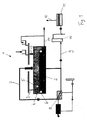
- Fig. 1 is a schematic diagram of a belt dryer according to the invention
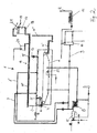
- Fig. 2 is a diagram of a belt drying system according to the invention
- Fig. 3 is a longitudinal view
- Fig. 4 is a transverse view of a dryer according to the invention.
- 1 shows a diagram of a dryer 1 with a belt, in particular a belt 2, in which a material 3 to be dried is applied to the belt, in particular belt 2, via a distribution screw and subsequently homogenized by a calibrating roller 5.
- the band, in particular sieve belt can consist of plastic or metal mesh.
- a level sensor 6 which controls the belt speed, with an increase in the level in the distribution screw, the belt, in particular wire belt accelerates or at a decrease in the level in the distribution screw, the belt speed is reduced until the level again has reached the setpoint.
- the coupled out of the air circuit laden with moisture air (vapors) is partially withdrawn via line 9, a condenser / saturator 10 and optionally a biofilter 11 supplied before the exhaust air 12 is discharged to the environment.
- This cooling air can be sucked in by a possibly existing in the dryer vacuum from the environment respectively as exhaust air from the peripheral components.
- Fig. 2 the same parts are provided with the same reference numerals as in Fig. 1.
- the possibility of hot air supply in two or more heating zones through line 7 and 7 ' is shown here.
- the heating in the heat exchanger 8 is carried out by the flue gases of a burner 15.
- the dried material for example granules, is fed by means of a screw conveyor 14 'and a conveying element 14 "to a back-mixing silo 16, from where the accept or final product 17 is discharged.
- the mixer can, as shown here consist of a delivery zone 19 'and an actual mixing zone 19 "and leads the mixed Good 3 of the distribution screw 6 to.
- the product discharge of the dried product from the dryer 1 takes place in the silo 16.
- the excess end product is discharged via a discharge screw 21 arranged in the upper region of the silo 16 and then different process steps, such as stacking in the silo, packaging in big bags, incineration or the like. fed.
- This arrangement represents a particularly cost-effective and reliable variant, since the discharge rate is controlled automatically. The more dried material is produced, the more good will be delivered. If less good, so nothing is discharged until again the level of the discharge screw 21 is reached. This also ensures that there is always enough material for backmixing. If the volume is selected accordingly, sufficient material will be available for restarting even if the system is switched off. Furthermore, there should also be enough space to completely empty the dryer when shutting down the system. Furthermore, the spray pipes 22 can be seen, by means of which water for condensation respectively.
- FIG. 3 shows a longitudinal view of the dryer 1 in the background of the mixer 19 and the silos 16 and 20 can be seen.
- Fig. 4 is a transverse view of a dryer 1 according to the invention can be seen. Here you can also see the Nassgutsilo 20 and the mixer 19 and the air supply line 7, including heat exchanger 8 and burner 15. Furthermore, the dryer hood 23 can be seen above the belt 2 in this view.
Landscapes
- Engineering & Computer Science (AREA)
- Mechanical Engineering (AREA)
- General Engineering & Computer Science (AREA)
- Drying Of Solid Materials (AREA)
- Treatment Of Sludge (AREA)
Abstract
Description
Ziel der Erfindung ist es daher ein Verfahren und eine Vorrichtung anzugeben, mit der eine gleichmäßige Verteilung des zu trocknenden Gutes, insbesondere pastöse und/oder klebrige Substanzen, auf das Band, insbesondere Siebband eines Bandtrockners gewährleistet wird.
Die Erfindung ist daher dadurch gekennzeichnet, dass zum Aufbringen des Gutes auf das Band, insbesondere Siebband am Eintritt eine Verteilschnecke über dem Band, insbesondere Siebband angeordnet ist. Durch diese Ausführung können zu trocknende Güter, wie z.B. Holzschnitzel, Biomasse, Getreide, Rejekte in Papierfabriken, aber auch Hausmüll oder Klärschlamm relativ gleichmäßig über das Band, insbesondere Siebband des Trockners verteilen.
Eine vorteilhafte Weiterbildung der Erfindung ist dadurch gekennzeichnet, dass eine Kalibrierwalze über dem Band, insbesondere Siebband angeordnet ist, wobei die Kalibrierwalze höhenverstellbar ausgeführt sein kann. Wenn zusätzlich im Bereich der Verteilschnecke ein Niveausensor angeordnet ist, wird eine noch gleichmäßigere Verteilung für die Trocknung erreicht.
Vorteilhaft hat sich erwiesen, wenn die Kalibrierwalze entgegen der Förderrichtung des Band, insbesondere Siebbandes rotiert, wobei die Rotationsgeschwindigkeit größer, als die Bandgeschwindigkeit sein kann. Damit wird die zu große Menge an zu trocknendem Gut wieder zurück in den Bereich der Verteilschnecke gefördert und somit eine noch gleichmäßigere Verteilung erzielt.
Für die Trocknung von pastösen und/oder klebrigen Substanzen, wie z.B. Klärschlamm ist es vorteilhaft, wenn die Verteilschnecke mit einem Mischer zur Vermischung von Rückmischgut, insbesondere einem Teilstrom des trockenen Endproduktes, und Frischgut, insbesondere Nassschlamm, in Verbindung steht, wobei der Mischer ein Pflugscharmischer, Doppelwellenmischer oder Paddelmischer sein kann. Durch eine Rückmischung von bereits getrocknetem Gut mit frischem Gut, beispielsweise Nassschlamm, kann die Luftdurchlässigkeit dieser pastösen und/oder klebrigen Substanzen eingestellt werden und es wird die gleichmäßige Verteilung auf dem Band, insbesondere Siebband begünstigt.
Wird der Mischer mit einer Austragsvorrichtung für Rückmischgut eines Rückmischsilos verbunden und weist der Rückmischsilo eine Austragsvorrichtung, insbesondere Austragsschnecke, für den Gutstoff, beispielsweise Granulat, auf, kann eine besonders kostengünstige und betriebsichere Anlage errichtet werden, bei der sich die Austragsmenge des Gutstoffs, z.B. Granulat selbsttätig regelt.
Eine besonders kostengünstige Variante eines Trockners lässt sich realisieren, wenn über dem Band, insbesondere Siebband eine Trockenhaube angeordnet ist, die sich über das gesamte Band, insbesondere Siebband inklusive Verteilschnecke erstreckt, wobei der Trockner Zuführleitungen aufweisen kann, die sich entlang der beiden Seiten des Trockners erstrecken und Öffnungen für den Austritt von Trocknungsgas aufweisen.
Sind die Zuführleitungen mittels einstellbarer Zugstangen miteinander verbunden, kann die Trockenhaube in sehr leichter Bauweise ausgeführt und für eine optimale Abdichtung gegenüber dem Gerüst des Trockners eingestellt werden.
Bei Trocknern mit großer Durchsatzleitung ergibt sich eine kostengünstige Bauart durch die Ausführung des Trocknerunterteiles oder des gesamten Trocknergehäuses in Beton.
Zur Entlastung der Umwelt durch Kondensation der Brüden oder Nachbehandlung in einem Biofilter hat es sich als vorteilhaft gezeigt, wenn unterhalb des Bandes, insbesondere Siebbandes Verteileinrichtungen, insbesondere Spritzrohre vorgesehen sind.
Die Erfindung betrifft auch ein Verfahren zum Trocknen von Gut, insbesondere Klärschlamm, wobei das Gut auf einem Band, insbesondere Siebband durch einen Trockner gefördert wird. Sie ist dadurch gekennzeichnet, dass das Gut über eine Verteilschnecke zugeführt wird, wobei das Niveau durch Änderung der Bandgeschwindigkeit verändert wird, wobei bei einem Ansteigen des Niveaus in der Verteilschnecke das Band, insbesondere Siebband beschleunigt bzw. bei einem Absinken des Niveaus in der Verteilschnecke die Bandgeschwindigkeit verringert werden kann, bis das Niveau wieder den Sollwert erreicht hat.
Zur Entlastung der Umwelt ist es vorteilhaft, wenn unterhalb des Bandes, insbesondere Siebbandes im Trockner Wasser eingesprüht wird und die Brüden kondensiert resp. gesättigt werden.
Die Erfindung wird nun anhand der Zeichnungen beispielhaft beschrieben, wobei Fig. 1 ein Prinzipschema eines erfindungsgemäßen Bandtrockners, Fig. 2 ein Schema einer erfindungsgemäßen Bandtrocknungsanlage, Fig. 3 eine Längsansicht und Fig. 4 eine Queransicht eines erfindungsgemäßen Trockners zeigen.
Fig. 1 stellt ein Schema eines Trockners 1 mit einem Band, insbesondere Siebband 2 dar, bei dem ein zu trocknendes Gut 3 über eine Verteilschnecke auf das Band, insbesondere Siebband 2 aufgetragen und anschließend durch eine Kalibrierwalze 5 vergleichmässigt wird. Das Band, insbesondere Siebband kann dabei aus Kunststoff oder Metallgewebe bestehen. Im Bereich der Verteilschnecke 4 ist ein Niveausensor 6 angeordnet, der die Bandgeschwindigkeit steuert, wobei bei einem Ansteigen des Niveaus in der Verteilschnecke das Band, insbesondere Siebband beschleunigt bzw. bei einem Absinken des Niveaus in der Verteilschnecke die Bandgeschwindigkeit verringert wird, bis das Niveau wieder den Sollwert erreicht hat. Durch das Zurückwerfen des Gutes durch die Kalibrierwalze 5 wird einerseits nach der Kalibrierwalze eine gleichmäßige Verteilung erreicht, andererseits wird bei höherer Zufuhrmenge, diese in den Bereich des Sensors geführt, wodurch die Regelung der Bandgeschwindigkeit rasch anspricht.
Die Trocknung erfolgt durch über Umluftleitung 7 zugeführte heiße Luft, die hier beispielhaft in einem Wärmetauscher 8 mittels Abwärmenutzung z.B. durch Dampf, Rauchgas oder Heißwasser aufgewärmt wird. Die Luft kann dabei auch direkt oder indirekt durch einen Brenner aufgeheizt werden. Die aus dem Luftkreislauf ausgekoppelte mit Feuchtigkeit beladene Luft (Brüden) wird teilweise über Leitung 9 abgezogen, einem Kondensator/Sättiger 10 und gegebenenfalls einem Biofilter 11 zugeführt, bevor die Abluft 12 an die Umgebung abgegeben wird. Bevor das getrocknete Gut 14 aus dem Trockner austritt wird es vorteilhafterweise noch durch Kühlluft 13 abgekühlt. Diese Kühlluft kann durch einen allenfalls im Trockner vorhandenen Unterdruck aus der Umgebung respektive als Absaugluft aus den Peripheriekomponenten angesaugt werden.
In Fig. 2 sind dieselben Teile mit denselben Bezugszeichen versehen wie in Fig. 1. Zusätzlich ist hier die Möglichkeit der Heißluftzufuhr in zwei oder mehrere Heizzonen durch Leitung 7 und 7' dargestellt. Die Aufwärmung im Wärmetauscher 8 erfolgt durch die Rauchgase eines Brenners 15. Daneben gibt es die Möglichkeit der Aufwärmung auch z.B. durch Heißwasser, Dampf oder ein Thermalöl.
Das getrocknete Gut, beispielsweise Granulat wird mittels einer Förderschnecke 14' und einem Förderelement 14" einem Rückmischsilo 16 zugeführt, von wo der Gutstoff bzw. das Endprodukt 17 abgeführt wird. Das Rückmischprodukt wird mittels der Dosierschnecken 18 dem Mischer 19 zugeführt und mit Frischgut bzw. Nassschlamm aus einem Vorlagebehälter 20 vermischt. Der Mischer kann, wie hier dargestellt aus einer Förderzone 19' und einer eigentlichen Mischzone 19" bestehen und führt das vermischte Gut 3 der Verteilschnecke 6 zu. Die Produktabgabe des getrockneten Produktes vom Trockner 1 erfolgt in den Silo 16. Das überschüssige Endprodukt wird über eine im oberen Bereich des Silos 16 angeordnete Austragsschnecke 21 ausgetragen und dann unterschiedlichen Prozessschritten, wie z.B. Stapelung im Silo, Verpackung in Big Bags, Verbrennung oder dgl. zugeführt. Diese Anordnung stellt eine besonders kostengünstige und betriebssichere Variante dar, da die Austragsmenge sich selbsttätig regelt. Je mehr getrocknetes Gut anfällt, desto mehr Gut wird ausgetragen. Fällt weniger Gut an, so wird solange nichts ausgetragen, bis wieder das Niveau der Austragsschnecke 21 erreicht ist. So ist auch gewährleistet, dass immer ausreichend Material für die Rückmischung vorhanden ist. Wird das Volumen entsprechend gewählt, ist auch bei einem Abstellen der Anlage ausreichend Material für das Wiederanfahren vorhanden. Weiters sollte auch genügend Raum sein, um beim Abfahren der Anlage den Trockner vollständig zu entleeren. Weiters sind die Spritzrohre 22 erkennbar, mittels deren Wasser zur Kondensation resp. Sättigung der Brüden eingesprüht wird.
Fig. 3 zeigt eine Längsansicht des Trockners 1 bei dem im Hintergrund der Mischer 19 sowie die Silos 16 und 20 erkennbar sind.
In Fig. 4 ist eine Queransicht eines erfindungsgemäßen Trockners 1 zu sehen. Hier erkennt man ebenfalls das Nassgutsilo 20 und den Mischer 19 sowie die Luftzufuhrleitung 7 samt Wärmetauscher 8 und Brenner 15. Weiters ist in dieser Ansicht die Trockenhaube 23 über dem Band 2 zu erkennen.
Claims (22)
- Vorrichtung zum kontinuierlichen Trocknen von Gut, insbesondere von Klärschlamm, mit einem Band (2), insbesondere Siebband auf dem das Gut gefördert wird, dadurch gekennzeichnet, dass zum Aufbringen des Gutes auf das Band (2), insbesondere Siebband am Eintritt eine Verteilschnecke (4) über dem Band (2), insbesondere Siebband angeordnet ist.
- Vorrichtung nach Anspruch 1, dadurch gekennzeichnet, dass im Bereich der Verteilschnecke (4) ein Niveausensor (6) angeordnet ist.
- Vorrichtung nach Anspruch 1 oder 2, dadurch gekennzeichnet, dass zusätzlich eine Kalibrierwalze (5) über dem Band (2), insbesondere Siebband angeordnet ist.
- Vorrichtung nach Anspruch 3, dadurch gekennzeichnet, dass die Kalibrierwalze (5) höhenverstellbar ausgeführt ist.
- Vorrichtung nach Anspruch 3 oder 4, dadurch gekennzeichnet, dass die Kalibrierwalze (5) entgegen der Förderrichtung des Bandes (2), insbesondere Siebbandes rotiert.
- Vorrichtung nach Anspruch 5, dadurch gekennzeichnet, dass die Rotationsgeschwindigkeit größer ist, als die Bandgeschwindigkeit.
- Vorrichtung nach einem der Ansprüche 1 bis 6, dadurch gekennzeichnet, dass die Verteilschnecke (4) mit einem Mischer (19) zur Vermischung von Rückmischgut, insbesondere getrocknetem Endprodukt, und Frischgut, insbesondere Nassschlamm, in Verbindung steht.
- Vorrichtung nach Anspruch 7, dadurch gekennzeichnet, dass der Mischer (19) ein Pflugscharmischer, Doppelwellenmischer oder Paddelmischer ist.
- Vorrichtung nach Anspruch 8, dadurch gekennzeichnet, dass der Mischer (19) mit einer Austragsvorrichtung (18) für Rückmischgut eines Rückmischsilos (16) in Verbindung steht und der Rückmischsilo (16) eine Austragsvorrichtung (21), insbesondere Austragsschnecke, für den Gutstoff, beispielsweise Granulat, aufweist.
- Vorrichtung nach einem der Ansprüche 1 bis 9, dadurch gekennzeichnet, dass über dem Band (2), insbesondere Siebband eine Trockenhaube (23) angeordnet ist, die sich über das gesamte Band (2), insbesondere Siebband inklusive Verteilschnecke (4) erstreckt.
- Vorrichtung nach einem der Ansprüche 1 bis 10, dadurch gekennzeichnet, dass das gesamte Trocknergehäuse oder Teile davon als Betonkonstruktion ausgeführt sind.
- Vorrichtung nach Anspruch 10 oder 11, dadurch gekennzeichnet, dass der Trockner (1) Zuführleitungen (7, 7') aufweist, die sich entlang der beiden Seiten des Trockners (1) erstrecken und Öffnungen für den Austritt von Trocknungsgas aufweisen.
- Vorrichtung nach Anspruch 12, dadurch gekennzeichnet, dass die Zuführleitungen (7, 7') mittels einstellbarer Zugstangen miteinander verbunden sind.
- Vorrichtung nach einem der Ansprüche 10 bis 13, dadurch gekennzeichnet, dass unterhalb des Bandes (2), insbesondere Siebbandes Verteileinrichtungen (22), insbesondere Spritzrohre zur Kondensation resp. Sättigung der Brüden vorgesehen sind.
- Verfahren zum Trocknen von Gut, insbesondere Klärschlamm, wobei das Gut auf einem Band, insbesondere Siebband durch einen Trockner gefördert wird, dadurch gekennzeichnet, dass das Gut über eine Verteilschnecke zugeführt wird, wobei das Niveau durch Änderung der Bandgeschwindigkeit verändert wird.
- Verfahren nach Anspruch 15, dadurch gekennzeichnet, dass die Luftdurchlässigkeit des zu trocknenden Gutes durch die Mischung des Frischproduktes mit einem Teilstrom des bereits getrockneten Endproduktes erreicht wird.
- Verfahren nach Anspruch 15 oder 16, dadurch gekennzeichnet, dass bei einem Ansteigen des Niveaus in der Verteilschnecke das Band, insbesondere Siebband beschleunigt wird, bis das Niveau wieder den Sollwert erreicht hat.
- Verfahren nach Anspruch 15 oder 16, dadurch gekennzeichnet, dass bei einem Absinken des Niveaus in der Verteilschnecke die Bandgeschwindigkeit verringert wird, bis das Niveau wieder den Sollwert erreicht hat.
- Verfahren nach einem der Ansprüche 15 bis 18, dadurch gekennzeichnet, dass das zu trocknende Gut von der Kalibrierwalze zurück in den Bereich der Verteilschnecke gefördert wird.
- Verfahren nach einem der Ansprüche 15 bis 19, dadurch gekennzeichnet, dass das zu trocknende Gut aus frischem Gut, insbesondere Nassschlamm, und rückgemischtem Gut, insbesondere Granulat, besteht, wobei das rückgemischte Gut mengengeregelt aus einem Vorratsbehälter, insbesondere Rückmischsilo, abgezogen wird.
- Verfahren nach Anspruch 20, dadurch gekennzeichnet, dass das überschüssige getrocknete Gut, insbesondere Granulat, als Gutstoff aus dem Vorratsbehälter abgezogen wird.
- Verfahren nach einem der Ansprüche 15 bis 21, dadurch gekennzeichnet, dass unterhalb des Bandes, insbesondere Siebbandes im Trockner Wasser eingesprüht wird und die Brüden kondensiert resp. gesättigt werden.
Priority Applications (2)
| Application Number | Priority Date | Filing Date | Title |
|---|---|---|---|
| PL04009190T PL1473533T3 (pl) | 2003-04-30 | 2004-04-19 | Sposób i urządzenie do ciągłego osuszania materiału, zwłaszcza osadu ze ścieków |
| SI200432256T SI1473533T1 (sl) | 2003-04-30 | 2004-04-19 | Postopek in aparat za kontinuirano sušenje materiala, še posebej kanalizacijskega blata |
Applications Claiming Priority (2)
| Application Number | Priority Date | Filing Date | Title |
|---|---|---|---|
| AT0066003A AT412277B (de) | 2003-04-30 | 2003-04-30 | Verfahren und vorrichtung zum kontinuierlichen trocknen von gut, insbesondere klärschlamm |
| AT6602003 | 2003-04-30 |
Publications (3)
| Publication Number | Publication Date |
|---|---|
| EP1473533A2 true EP1473533A2 (de) | 2004-11-03 |
| EP1473533A3 EP1473533A3 (de) | 2008-05-14 |
| EP1473533B1 EP1473533B1 (de) | 2015-06-17 |
Family
ID=32234886
Family Applications (1)
| Application Number | Title | Priority Date | Filing Date |
|---|---|---|---|
| EP04009190.2A Expired - Lifetime EP1473533B1 (de) | 2003-04-30 | 2004-04-19 | Verfahren und Vorrichtung zum kontinuierlichen Trocknen von Gut, insbesondere Klärschlamm |
Country Status (7)
| Country | Link |
|---|---|
| US (1) | US7028414B2 (de) |
| EP (1) | EP1473533B1 (de) |
| AT (1) | AT412277B (de) |
| ES (1) | ES2545902T3 (de) |
| HU (1) | HUE027613T2 (de) |
| PL (1) | PL1473533T3 (de) |
| SI (1) | SI1473533T1 (de) |
Cited By (6)
| Publication number | Priority date | Publication date | Assignee | Title |
|---|---|---|---|---|
| WO2012113601A1 (de) * | 2011-02-25 | 2012-08-30 | Huber Se | Anlage und verfahren zum trocknen von feuchtgut |
| DE102012207884A1 (de) | 2012-05-11 | 2013-11-14 | Easy Dry Systems AG | Vorrichtung zum Trocknen von Gut |
| WO2015128547A1 (en) * | 2014-02-28 | 2015-09-03 | Evac Oy | Waste treatment installation |
| US20170211883A1 (en) * | 2014-07-17 | 2017-07-27 | Officine Facco & C. S.P.A. | Drying machine for pasty and/or granular substances and spacer for rollers of conveyor belts for such drying machine |
| CN112777915A (zh) * | 2021-03-04 | 2021-05-11 | 天津科技大学 | 一种小型密封污泥干化电动翻搅装置 |
| CN113531537A (zh) * | 2020-04-20 | 2021-10-22 | 宋钰婷 | 一种具有烟气水洗净化功能的空气环保式废物焚烧装置 |
Families Citing this family (23)
| Publication number | Priority date | Publication date | Assignee | Title |
|---|---|---|---|---|
| AT503896B1 (de) * | 2006-06-21 | 2008-10-15 | Andritz Tech & Asset Man Gmbh | Verfahren und anlage zur verarbeitung von feuchtgut |
| WO2008106672A2 (en) * | 2007-03-01 | 2008-09-04 | Andritz Separation Inc. | System and method for treatment of pathogens in dried sewage sludge |
| US9708540B2 (en) | 2008-04-10 | 2017-07-18 | The Crucible Group Pty Ltd | Processing organic materials |
| CA2721043C (en) * | 2008-04-10 | 2018-05-15 | The Crucible Group Pty Ltd | Method and apparatus for drying and pyrolysing solid organic feed material |
| US8673156B2 (en) * | 2008-10-02 | 2014-03-18 | Gryphon Environmental, Llc | Suspension liquid extraction apparatus and method |
| FR2954814B1 (fr) * | 2009-12-30 | 2012-03-02 | Degremont | Procede et installation de sechage de matieres pateuses, en particulier de boues de stations d'epuration, avec generation d'energie thermique. |
| KR102304049B1 (ko) * | 2014-01-10 | 2021-09-17 | 츠키시마기카이가부시키가이샤 | 미분 슬러리의 고액 분리·건조 설비 및 그 방법 |
| DE102014013078B4 (de) * | 2014-09-09 | 2016-12-29 | Biotherm Services Gmbh | Verfahren und Vorrichtung zur Behandlung von phosphorhaltigem Klärschlamm |
| DE102015106120A1 (de) * | 2015-04-21 | 2016-10-27 | Huber Se | Verfahren zum Trocknen von Feuchtgut sowie Trocknungsanlage |
| CN105688750A (zh) * | 2016-01-19 | 2016-06-22 | 浙江丽水有邦新材料有限公司 | 一种防腐的回转凝固造粒机 |
| CA2959851C (en) * | 2016-03-03 | 2026-04-07 | Recover Energy Services Inc. | Gas tight shale shaker for enhanced drilling fluid recovery and drilled solids washing |
| CN111296868A (zh) * | 2018-12-12 | 2020-06-19 | 石柱土家族自治县卓远农业开发有限公司 | 新鲜黄花菜多级烘干机 |
| CN112268428A (zh) * | 2020-09-05 | 2021-01-26 | 江苏吉能达环境能源科技有限公司 | 一种废石英砂滤料再生处理机的烘干装置 |
| CN112696911A (zh) * | 2020-10-19 | 2021-04-23 | 李刚 | 一种用于饲料加工的干燥装置 |
| CN112393552A (zh) * | 2020-10-29 | 2021-02-23 | 德清凯晶光电科技有限公司 | 一种烘干效果好的颗粒状物质烘干机械设备 |
| CN112595084B (zh) * | 2020-12-16 | 2022-11-22 | 苏州推动者生物科技有限公司 | 一种用于小型昆虫的干燥装置及处理系统 |
| CN113340061B (zh) * | 2021-06-17 | 2022-04-26 | 合肥工业大学 | 一种大豆磷脂浓缩液高效干燥装置 |
| CN113883873A (zh) * | 2021-10-18 | 2022-01-04 | 安徽云龙粮机有限公司 | 基于粮食加工的高效循环烘干装置 |
| CN114136077A (zh) * | 2021-11-24 | 2022-03-04 | 镇江荣诚管业有限公司 | 一种pp管材生产原料干燥装置及其使用方法 |
| CN116007331B (zh) * | 2022-12-28 | 2024-11-29 | 湖南省农友盛泰农业科技有限公司 | 一种多功能烘干机 |
| CN116447856B (zh) * | 2023-06-09 | 2024-05-07 | 盛胜电子科技(广州)有限公司 | 一种集装箱式煤炭低温烘干机及烘干方法 |
| CN117073350B (zh) * | 2023-08-09 | 2026-02-13 | 苏州市协力环保设备有限公司 | 一种减少带式预干燥机颗粒物排放的机构及工艺方法 |
| CN117404893B (zh) * | 2023-12-15 | 2024-03-08 | 广东省迪华智能装备有限公司 | 一种自动烘干机 |
Citations (13)
| Publication number | Priority date | Publication date | Assignee | Title |
|---|---|---|---|---|
| GB812043A (en) | 1957-06-18 | 1959-04-15 | Firestone Tire & Rubber Co | Method and apparatus for drying and cooling pellets of rubbery or plastic material |
| GB940088A (en) | 1961-11-01 | 1963-10-23 | Haas Friedrich Maschf | A method and apparatus for the continuous treatment of loosely matted fibrous materials especially the drying and carbonising thereof |
| GB1013632A (en) | 1963-08-09 | 1965-12-15 | Friedrich Haas Gmbh Maschf | Belt dryer |
| GB1361065A (en) | 1970-08-31 | 1974-07-24 | Ruigrok H C M | Forage crop dryer |
| JPS63137598A (ja) | 1986-11-28 | 1988-06-09 | Mitsubishi Kakoki Kaisha Ltd | ベルトプレス型脱水装置 |
| HUT48804A (en) | 1987-06-23 | 1989-07-28 | Attila Bodo | Steam-operated blanching apparatus particularly for servicing conserve industrial production lines serving for processing fruitery and vegetables |
| WO1992000250A1 (en) | 1990-06-28 | 1992-01-09 | Blue-Tec A/S | A method and a system for drying sludge |
| DE4116146A1 (de) | 1990-10-18 | 1992-04-23 | Klein Alb Gmbh Co Kg | Verfahren zum entwaessern von suspensionen od. dgl. schlammartigen gemischen |
| DE9307012U1 (de) | 1993-05-08 | 1993-07-15 | Gebr. Bellmer GmbH & Co. KG, 7532 Niefern-Öschelbronn | Vorrichtung zur Verteilung von Schlamm |
| DE4205619A1 (de) | 1992-02-25 | 1993-08-26 | Gea Canzler Gmbh & Co | Verfahren und vorrichtung zur reduzierung des fluessigkeitsgehalts von gemischen von feststoffen und fluessigkeiten |
| JPH1059534A (ja) | 1996-08-14 | 1998-03-03 | Nippon Shokubai Co Ltd | 粘着性粉粒状物群用ならし装置 |
| EP0781741B1 (de) | 1995-12-27 | 1999-07-28 | Sestino-Anstalt | Verfahren zur Verarbeitung von Schlamm |
| EP0889014B1 (de) | 1997-07-01 | 2001-02-28 | Innoplana Umwelttechnik AG | Verfahren zur Verarbeitung von Schlamm |
Family Cites Families (17)
| Publication number | Priority date | Publication date | Assignee | Title |
|---|---|---|---|---|
| DE947450C (de) | 1950-12-31 | 1956-08-16 | August Gronert | Bandtrockner, insbesondere fuer landwirtschaftliche Erzeugnisse |
| BE791761A (fr) | 1971-12-07 | 1973-03-16 | Krueger As I | Appareil de sechage pour les boues d'egout |
| DE7202548U (de) | 1972-01-25 | 1973-06-14 | Sandco Ltd, Ottawa, (Kanada) | Vorrichtung zum aufbereiten von schlamm |
| US3864840A (en) * | 1973-07-16 | 1975-02-11 | Matthews Jr Donnell R | Lyophilic waste disposal |
| DE2804585A1 (de) * | 1978-02-03 | 1979-08-09 | Schenck Ag Carl | Einrichtung zur vergleichmaessigung von schuettgut |
| US4263239A (en) * | 1978-09-18 | 1981-04-21 | Courtaulds Limited | Dry forming of fibrous material |
| US4245396A (en) * | 1979-07-09 | 1981-01-20 | Uop Inc. | Process for drying and granulating sewage sludge |
| US4580698A (en) * | 1983-05-25 | 1986-04-08 | Pebco, Inc. | Automatically adjustable continuous feeder system |
| DE3531748A1 (de) | 1985-09-05 | 1987-03-05 | Gfd Ges Fuer Dosiertechnik Mbh | Klaerschlammverwertungsanlage |
| DE3616966A1 (de) | 1986-05-20 | 1987-11-26 | Dornier Gmbh Lindauer | Trockner fuer ein in kontinuierlicher bahn durchgefuehrtes gut |
| NL8801037A (nl) * | 1988-04-21 | 1989-11-16 | Pannevis Bv | Werkwijze en inrichting voor het verwijderen van vloeistof uit een mengsel van vaste stof en vloeistof. |
| DE4218699C2 (de) * | 1992-06-09 | 2000-01-20 | Dornier Gmbh Lindauer | Durchström-Trockner zur Trocknung von Schlämmen mit Filteranordnung |
| DE4235422C2 (de) | 1992-10-21 | 1997-01-23 | Dornier Gmbh Lindauer | Verfahren zum Trocknen von vorzugsweise in pelletierter Form vorliegenden pastösen Material, insbesondere Klärschlamm und Vorrichtung zur Durchführung des Verfahrens |
| DE4320170C2 (de) * | 1993-06-18 | 1998-07-02 | Bat Cigarettenfab Gmbh | Verfahren und Vorrichtung zur Kühlung von Tabakmaterial |
| DE4336736A1 (de) * | 1993-10-28 | 1995-05-04 | Bayer Ag | Vorrichtung zum kontinuierlichen Filtrieren und Trocknen einer Feststoffsuspension |
| DE9419080U1 (de) * | 1994-11-29 | 1995-01-12 | Gebr. Bellmer GmbH & Co. KG, 75223 Niefern-Öschelbronn | Vorrichtung zur gleichmäßigen Aufbringung von Stoffen auf eine Aufgabefläche |
| AU2343897A (en) * | 1996-03-21 | 1997-10-10 | Eco Technology, Inc. | Sludge drying apparatus and process |
-
2003
- 2003-04-30 AT AT0066003A patent/AT412277B/de not_active IP Right Cessation
-
2004
- 2004-04-19 PL PL04009190T patent/PL1473533T3/pl unknown
- 2004-04-19 HU HUE04009190A patent/HUE027613T2/en unknown
- 2004-04-19 ES ES04009190.2T patent/ES2545902T3/es not_active Expired - Lifetime
- 2004-04-19 EP EP04009190.2A patent/EP1473533B1/de not_active Expired - Lifetime
- 2004-04-19 SI SI200432256T patent/SI1473533T1/sl unknown
- 2004-04-29 US US10/835,489 patent/US7028414B2/en not_active Expired - Lifetime
Patent Citations (13)
| Publication number | Priority date | Publication date | Assignee | Title |
|---|---|---|---|---|
| GB812043A (en) | 1957-06-18 | 1959-04-15 | Firestone Tire & Rubber Co | Method and apparatus for drying and cooling pellets of rubbery or plastic material |
| GB940088A (en) | 1961-11-01 | 1963-10-23 | Haas Friedrich Maschf | A method and apparatus for the continuous treatment of loosely matted fibrous materials especially the drying and carbonising thereof |
| GB1013632A (en) | 1963-08-09 | 1965-12-15 | Friedrich Haas Gmbh Maschf | Belt dryer |
| GB1361065A (en) | 1970-08-31 | 1974-07-24 | Ruigrok H C M | Forage crop dryer |
| JPS63137598A (ja) | 1986-11-28 | 1988-06-09 | Mitsubishi Kakoki Kaisha Ltd | ベルトプレス型脱水装置 |
| HUT48804A (en) | 1987-06-23 | 1989-07-28 | Attila Bodo | Steam-operated blanching apparatus particularly for servicing conserve industrial production lines serving for processing fruitery and vegetables |
| WO1992000250A1 (en) | 1990-06-28 | 1992-01-09 | Blue-Tec A/S | A method and a system for drying sludge |
| DE4116146A1 (de) | 1990-10-18 | 1992-04-23 | Klein Alb Gmbh Co Kg | Verfahren zum entwaessern von suspensionen od. dgl. schlammartigen gemischen |
| DE4205619A1 (de) | 1992-02-25 | 1993-08-26 | Gea Canzler Gmbh & Co | Verfahren und vorrichtung zur reduzierung des fluessigkeitsgehalts von gemischen von feststoffen und fluessigkeiten |
| DE9307012U1 (de) | 1993-05-08 | 1993-07-15 | Gebr. Bellmer GmbH & Co. KG, 7532 Niefern-Öschelbronn | Vorrichtung zur Verteilung von Schlamm |
| EP0781741B1 (de) | 1995-12-27 | 1999-07-28 | Sestino-Anstalt | Verfahren zur Verarbeitung von Schlamm |
| JPH1059534A (ja) | 1996-08-14 | 1998-03-03 | Nippon Shokubai Co Ltd | 粘着性粉粒状物群用ならし装置 |
| EP0889014B1 (de) | 1997-07-01 | 2001-02-28 | Innoplana Umwelttechnik AG | Verfahren zur Verarbeitung von Schlamm |
Cited By (8)
| Publication number | Priority date | Publication date | Assignee | Title |
|---|---|---|---|---|
| WO2012113601A1 (de) * | 2011-02-25 | 2012-08-30 | Huber Se | Anlage und verfahren zum trocknen von feuchtgut |
| DE102012207884A1 (de) | 2012-05-11 | 2013-11-14 | Easy Dry Systems AG | Vorrichtung zum Trocknen von Gut |
| DE102012207884B4 (de) * | 2012-05-11 | 2014-04-24 | Easy Dry Systems AG | Vorrichtung zum Trocknen von Gut |
| WO2015128547A1 (en) * | 2014-02-28 | 2015-09-03 | Evac Oy | Waste treatment installation |
| US20170211883A1 (en) * | 2014-07-17 | 2017-07-27 | Officine Facco & C. S.P.A. | Drying machine for pasty and/or granular substances and spacer for rollers of conveyor belts for such drying machine |
| US10337795B2 (en) * | 2014-07-17 | 2019-07-02 | Officine Facco & C. S.P.A. | Drying machine for pasty and/or granular substances and spacer for rollers of conveyor belts for such drying machine |
| CN113531537A (zh) * | 2020-04-20 | 2021-10-22 | 宋钰婷 | 一种具有烟气水洗净化功能的空气环保式废物焚烧装置 |
| CN112777915A (zh) * | 2021-03-04 | 2021-05-11 | 天津科技大学 | 一种小型密封污泥干化电动翻搅装置 |
Also Published As
| Publication number | Publication date |
|---|---|
| AT412277B (de) | 2004-12-27 |
| US20050241173A1 (en) | 2005-11-03 |
| US7028414B2 (en) | 2006-04-18 |
| ES2545902T3 (es) | 2015-09-16 |
| ATA6602003A (de) | 2004-05-15 |
| EP1473533A3 (de) | 2008-05-14 |
| PL1473533T3 (pl) | 2015-11-30 |
| EP1473533B1 (de) | 2015-06-17 |
| HUE027613T2 (en) | 2016-10-28 |
| SI1473533T1 (sl) | 2015-09-30 |
Similar Documents
| Publication | Publication Date | Title |
|---|---|---|
| EP1473533B1 (de) | Verfahren und Vorrichtung zum kontinuierlichen Trocknen von Gut, insbesondere Klärschlamm | |
| AT515466B1 (de) | Verfahren zur Trocknung von Schüttgut | |
| CH662752A5 (de) | Verfahren zum behandeln eines teilchenfoermigen gutes und einrichtung zur durchfuehrung des verfahrens. | |
| EP0210196A1 (de) | Verfahren und vorrichtung zum trocknen und konditionieren von hühnermist oder ähnlichen pastösen stoffen. | |
| DE3234431A1 (de) | Verfahren und vorrichtung zur abfuehrung von gasen und daempfen aus mit schuettgut gefuelltem trocknungstrichter | |
| DE10352106A1 (de) | Verfahren zur Steuerung des Gasdurchsatzes durch Schüttgüter | |
| WO2010108806A1 (de) | Verfahren und vorrichtung zum trocknen von gütern | |
| DE102008046299B4 (de) | Verfahren und Vorrichtung zum Trocknen von Biomasse | |
| DE2941637A1 (de) | Anlage zur granuliertrocknung von biomassen und eiweisse | |
| EP0458221B1 (de) | Verfahren zum Trocknen von Klärschlamm | |
| DE4013761C2 (de) | Verfahren zum Trocknen von pastösem und/oder brockigem Material | |
| EP1319632A1 (de) | Verfahren und Vorrichtung zur Trocknung von Schlamm, insbesondere von Abwasserschlamm | |
| DE102005020992B3 (de) | Mehrstufige Coatingvorrichtung für Formkörper | |
| DE2611853A1 (de) | Verfahren zum trocknen landwirtschaftlicher futtermittel und schlammartiger materialien | |
| DE202009001935U1 (de) | Einbandtrockner | |
| AT520600B1 (de) | Vorrichtung und Verfahren zum Trocknen von Schüttgut | |
| DE69800889T2 (de) | Verfahren zum betreiben einer trocknungsvorrichtung, sowie eine vorrichtung zur durchführung dieses verfahrens | |
| EP0781741B1 (de) | Verfahren zur Verarbeitung von Schlamm | |
| EP0945409A2 (de) | Anlage zum Trocknen von Schlämmen | |
| DE4022718A1 (de) | Verfahren und vorrichtung zum trocknen von tabak oder einem aehnlichen gut | |
| DD271813A3 (de) | Trockenbehaelter | |
| EP1453763B1 (de) | Verfahren und vorrichtung zur trocknung von schlamm, insbesondere von abwasserschlamm | |
| EP0889014B1 (de) | Verfahren zur Verarbeitung von Schlamm | |
| DE3836004C2 (de) | ||
| DE3939663A1 (de) | Verfahren und vorrichtung zum reinigen von metallspaenen |
Legal Events
| Date | Code | Title | Description |
|---|---|---|---|
| PUAI | Public reference made under article 153(3) epc to a published international application that has entered the european phase |
Free format text: ORIGINAL CODE: 0009012 |
|
| AK | Designated contracting states |
Kind code of ref document: A2 Designated state(s): AT BE BG CH CY CZ DE DK EE ES FI FR GB GR HU IE IT LI LU MC NL PL PT RO SE SI SK TR |
|
| AX | Request for extension of the european patent |
Extension state: AL HR LT LV MK |
|
| PUAL | Search report despatched |
Free format text: ORIGINAL CODE: 0009013 |
|
| AK | Designated contracting states |
Kind code of ref document: A3 Designated state(s): AT BE BG CH CY CZ DE DK EE ES FI FR GB GR HU IE IT LI LU MC NL PL PT RO SE SI SK TR |
|
| AX | Request for extension of the european patent |
Extension state: AL HR LT LV MK |
|
| 17P | Request for examination filed |
Effective date: 20081112 |
|
| AKX | Designation fees paid |
Designated state(s): AT BE BG CH CY CZ DE DK EE ES FI FR GB GR HU IE IT LI LU MC NL PL PT RO SE SI SK TR |
|
| TPAC | Observations filed by third parties |
Free format text: ORIGINAL CODE: EPIDOSNTIPA |
|
| 17Q | First examination report despatched |
Effective date: 20090515 |
|
| TPAC | Observations filed by third parties |
Free format text: ORIGINAL CODE: EPIDOSNTIPA |
|
| GRAP | Despatch of communication of intention to grant a patent |
Free format text: ORIGINAL CODE: EPIDOSNIGR1 |
|
| INTG | Intention to grant announced |
Effective date: 20150108 |
|
| GRAS | Grant fee paid |
Free format text: ORIGINAL CODE: EPIDOSNIGR3 |
|
| GRAA | (expected) grant |
Free format text: ORIGINAL CODE: 0009210 |
|
| AK | Designated contracting states |
Kind code of ref document: B1 Designated state(s): AT BE BG CH CY CZ DE DK EE ES FI FR GB GR HU IE IT LI LU MC NL PL PT RO SE SI SK TR |
|
| REG | Reference to a national code |
Ref country code: GB Ref legal event code: FG4D Free format text: NOT ENGLISH |
|
| REG | Reference to a national code |
Ref country code: CH Ref legal event code: EP |
|
| REG | Reference to a national code |
Ref country code: AT Ref legal event code: REF Ref document number: 732178 Country of ref document: AT Kind code of ref document: T Effective date: 20150715 |
|
| REG | Reference to a national code |
Ref country code: IE Ref legal event code: FG4D Free format text: LANGUAGE OF EP DOCUMENT: GERMAN |
|
| REG | Reference to a national code |
Ref country code: DE Ref legal event code: R096 Ref document number: 502004014925 Country of ref document: DE |
|
| REG | Reference to a national code |
Ref country code: ES Ref legal event code: FG2A Ref document number: 2545902 Country of ref document: ES Kind code of ref document: T3 Effective date: 20150916 |
|
| PG25 | Lapsed in a contracting state [announced via postgrant information from national office to epo] |
Ref country code: FI Free format text: LAPSE BECAUSE OF FAILURE TO SUBMIT A TRANSLATION OF THE DESCRIPTION OR TO PAY THE FEE WITHIN THE PRESCRIBED TIME-LIMIT Effective date: 20150617 |
|
| REG | Reference to a national code |
Ref country code: EE Ref legal event code: FG4A Ref document number: E011053 Country of ref document: EE Effective date: 20150910 |
|
| REG | Reference to a national code |
Ref country code: RO Ref legal event code: EPE |
|
| REG | Reference to a national code |
Ref country code: NL Ref legal event code: MP Effective date: 20150617 |
|
| PG25 | Lapsed in a contracting state [announced via postgrant information from national office to epo] |
Ref country code: GR Free format text: LAPSE BECAUSE OF FAILURE TO SUBMIT A TRANSLATION OF THE DESCRIPTION OR TO PAY THE FEE WITHIN THE PRESCRIBED TIME-LIMIT Effective date: 20150918 |
|
| REG | Reference to a national code |
Ref country code: PL Ref legal event code: T3 |
|
| REG | Reference to a national code |
Ref country code: SK Ref legal event code: T3 Ref document number: E 19369 Country of ref document: SK |
|
| PG25 | Lapsed in a contracting state [announced via postgrant information from national office to epo] |
Ref country code: PT Free format text: LAPSE BECAUSE OF FAILURE TO SUBMIT A TRANSLATION OF THE DESCRIPTION OR TO PAY THE FEE WITHIN THE PRESCRIBED TIME-LIMIT Effective date: 20151019 |
|
| REG | Reference to a national code |
Ref country code: DE Ref legal event code: R026 Ref document number: 502004014925 Country of ref document: DE |
|
| PLBI | Opposition filed |
Free format text: ORIGINAL CODE: 0009260 |
|
| PLAX | Notice of opposition and request to file observation + time limit sent |
Free format text: ORIGINAL CODE: EPIDOSNOBS2 |
|
| 26 | Opposition filed |
Opponent name: SUELZLE KLEIN GMBH Effective date: 20160317 |
|
| PG25 | Lapsed in a contracting state [announced via postgrant information from national office to epo] |
Ref country code: DK Free format text: LAPSE BECAUSE OF FAILURE TO SUBMIT A TRANSLATION OF THE DESCRIPTION OR TO PAY THE FEE WITHIN THE PRESCRIBED TIME-LIMIT Effective date: 20150617 |
|
| PLBB | Reply of patent proprietor to notice(s) of opposition received |
Free format text: ORIGINAL CODE: EPIDOSNOBS3 |
|
| PG25 | Lapsed in a contracting state [announced via postgrant information from national office to epo] |
Ref country code: BE Free format text: LAPSE BECAUSE OF NON-PAYMENT OF DUE FEES Effective date: 20160430 |
|
| REG | Reference to a national code |
Ref country code: HU Ref legal event code: AG4A Ref document number: E027613 Country of ref document: HU |
|
| GBPC | Gb: european patent ceased through non-payment of renewal fee |
Effective date: 20160419 |
|
| PG25 | Lapsed in a contracting state [announced via postgrant information from national office to epo] |
Ref country code: LU Free format text: LAPSE BECAUSE OF FAILURE TO SUBMIT A TRANSLATION OF THE DESCRIPTION OR TO PAY THE FEE WITHIN THE PRESCRIBED TIME-LIMIT Effective date: 20160419 |
|
| REG | Reference to a national code |
Ref country code: IE Ref legal event code: MM4A |
|
| REG | Reference to a national code |
Ref country code: FR Ref legal event code: ST Effective date: 20161230 |
|
| PG25 | Lapsed in a contracting state [announced via postgrant information from national office to epo] |
Ref country code: GB Free format text: LAPSE BECAUSE OF NON-PAYMENT OF DUE FEES Effective date: 20160419 Ref country code: FR Free format text: LAPSE BECAUSE OF NON-PAYMENT OF DUE FEES Effective date: 20160502 |
|
| PG25 | Lapsed in a contracting state [announced via postgrant information from national office to epo] |
Ref country code: IE Free format text: LAPSE BECAUSE OF NON-PAYMENT OF DUE FEES Effective date: 20160419 |
|
| REG | Reference to a national code |
Ref country code: AT Ref legal event code: MM01 Ref document number: 732178 Country of ref document: AT Kind code of ref document: T Effective date: 20160419 |
|
| PG25 | Lapsed in a contracting state [announced via postgrant information from national office to epo] |
Ref country code: SE Free format text: LAPSE BECAUSE OF FAILURE TO SUBMIT A TRANSLATION OF THE DESCRIPTION OR TO PAY THE FEE WITHIN THE PRESCRIBED TIME-LIMIT Effective date: 20150617 Ref country code: NL Free format text: LAPSE BECAUSE OF FAILURE TO SUBMIT A TRANSLATION OF THE DESCRIPTION OR TO PAY THE FEE WITHIN THE PRESCRIBED TIME-LIMIT Effective date: 20150617 |
|
| PG25 | Lapsed in a contracting state [announced via postgrant information from national office to epo] |
Ref country code: AT Free format text: LAPSE BECAUSE OF NON-PAYMENT OF DUE FEES Effective date: 20160419 |
|
| PLCK | Communication despatched that opposition was rejected |
Free format text: ORIGINAL CODE: EPIDOSNREJ1 |
|
| STAA | Information on the status of an ep patent application or granted ep patent |
Free format text: STATUS: THE PATENT HAS BEEN GRANTED |
|
| APBM | Appeal reference recorded |
Free format text: ORIGINAL CODE: EPIDOSNREFNO |
|
| APBP | Date of receipt of notice of appeal recorded |
Free format text: ORIGINAL CODE: EPIDOSNNOA2O |
|
| APAH | Appeal reference modified |
Free format text: ORIGINAL CODE: EPIDOSCREFNO |
|
| PG25 | Lapsed in a contracting state [announced via postgrant information from national office to epo] |
Ref country code: CY Free format text: LAPSE BECAUSE OF FAILURE TO SUBMIT A TRANSLATION OF THE DESCRIPTION OR TO PAY THE FEE WITHIN THE PRESCRIBED TIME-LIMIT Effective date: 20150617 |
|
| APBQ | Date of receipt of statement of grounds of appeal recorded |
Free format text: ORIGINAL CODE: EPIDOSNNOA3O |
|
| PG25 | Lapsed in a contracting state [announced via postgrant information from national office to epo] |
Ref country code: TR Free format text: LAPSE BECAUSE OF FAILURE TO SUBMIT A TRANSLATION OF THE DESCRIPTION OR TO PAY THE FEE WITHIN THE PRESCRIBED TIME-LIMIT Effective date: 20150617 Ref country code: MC Free format text: LAPSE BECAUSE OF FAILURE TO SUBMIT A TRANSLATION OF THE DESCRIPTION OR TO PAY THE FEE WITHIN THE PRESCRIBED TIME-LIMIT Effective date: 20150617 |
|
| PGFP | Annual fee paid to national office [announced via postgrant information from national office to epo] |
Ref country code: CH Payment date: 20190715 Year of fee payment: 16 |
|
| REG | Reference to a national code |
Ref country code: CH Ref legal event code: PL |
|
| PG25 | Lapsed in a contracting state [announced via postgrant information from national office to epo] |
Ref country code: CH Free format text: LAPSE BECAUSE OF NON-PAYMENT OF DUE FEES Effective date: 20200430 Ref country code: LI Free format text: LAPSE BECAUSE OF NON-PAYMENT OF DUE FEES Effective date: 20200430 |
|
| REG | Reference to a national code |
Ref country code: DE Ref legal event code: R082 Ref document number: 502004014925 Country of ref document: DE Representative=s name: KILBURN & STRODE LLP, NL |
|
| REG | Reference to a national code |
Ref country code: DE Ref legal event code: R100 Ref document number: 502004014925 Country of ref document: DE |
|
| APBU | Appeal procedure closed |
Free format text: ORIGINAL CODE: EPIDOSNNOA9O |
|
| PLBN | Opposition rejected |
Free format text: ORIGINAL CODE: 0009273 |
|
| STAA | Information on the status of an ep patent application or granted ep patent |
Free format text: STATUS: OPPOSITION REJECTED |
|
| 27O | Opposition rejected |
Effective date: 20210830 |
|
| REG | Reference to a national code |
Ref country code: EE Ref legal event code: HC1A Ref document number: E011053 Country of ref document: EE |
|
| REG | Reference to a national code |
Ref country code: DE Ref legal event code: R081 Ref document number: 502004014925 Country of ref document: DE Owner name: ANDRITZ FLIESSBETT SYSTEME GMBH, DE Free format text: FORMER OWNER: VONPLON, ARMIN, OBERLUNKHOFEN, CH |
|
| REG | Reference to a national code |
Ref country code: ES Ref legal event code: PC2A Owner name: ANDRITZ FLIESSBETT SYSTEME GMBH Effective date: 20221004 |
|
| REG | Reference to a national code |
Ref country code: EE Ref legal event code: GB1A Ref document number: E011053 Country of ref document: EE |
|
| REG | Reference to a national code |
Ref country code: HU Ref legal event code: GB9C Owner name: ANDRITZ FLIESSBETT SYSTEME GMBH, DE Free format text: FORMER OWNER(S): VONPLON, ARMIN, CH Ref country code: HU Ref legal event code: FH1C Free format text: FORMER REPRESENTATIVE(S): SIPOS JOZSEF, DANUBIA SZABADALMI ES VEDJEGY IRODA KFT., HU Representative=s name: DANUBIA SZABADALMI ES JOGI IRODA KFT., HU |
|
| REG | Reference to a national code |
Ref country code: SK Ref legal event code: PC4A Ref document number: E 19369 Country of ref document: SK Owner name: ANDRITZ FLIESSBETT SYSTEME GMBH, RAVENSBURG, DE Free format text: FORMER OWNER: VONPLON ARMIN, OBERLUNKHOF, CH Effective date: 20221021 |
|
| REG | Reference to a national code |
Ref country code: SI Ref legal event code: SP73 Owner name: ANDRITZ FLIESSBETT SYSTEME GMBH; DE Effective date: 20221011 |
|
| P01 | Opt-out of the competence of the unified patent court (upc) registered |
Effective date: 20230428 |
|
| P02 | Opt-out of the competence of the unified patent court (upc) changed |
Effective date: 20230530 |
|
| PGFP | Annual fee paid to national office [announced via postgrant information from national office to epo] |
Ref country code: RO Payment date: 20230411 Year of fee payment: 20 Ref country code: IT Payment date: 20230426 Year of fee payment: 20 Ref country code: ES Payment date: 20230627 Year of fee payment: 20 Ref country code: EE Payment date: 20230414 Year of fee payment: 20 Ref country code: DE Payment date: 20230420 Year of fee payment: 20 Ref country code: CZ Payment date: 20230412 Year of fee payment: 20 Ref country code: BG Payment date: 20230420 Year of fee payment: 20 |
|
| PGFP | Annual fee paid to national office [announced via postgrant information from national office to epo] |
Ref country code: SK Payment date: 20230413 Year of fee payment: 20 Ref country code: SI Payment date: 20230406 Year of fee payment: 20 Ref country code: PL Payment date: 20230412 Year of fee payment: 20 Ref country code: HU Payment date: 20230421 Year of fee payment: 20 |
|
| REG | Reference to a national code |
Ref country code: DE Ref legal event code: R071 Ref document number: 502004014925 Country of ref document: DE |
|
| PG25 | Lapsed in a contracting state [announced via postgrant information from national office to epo] |
Ref country code: ES Free format text: LAPSE BECAUSE OF EXPIRATION OF PROTECTION Effective date: 20240420 |
|
| REG | Reference to a national code |
Ref country code: ES Ref legal event code: FD2A Effective date: 20240426 |
|
| PG25 | Lapsed in a contracting state [announced via postgrant information from national office to epo] |
Ref country code: ES Free format text: LAPSE BECAUSE OF EXPIRATION OF PROTECTION Effective date: 20240420 |
|
| PG25 | Lapsed in a contracting state [announced via postgrant information from national office to epo] |
Ref country code: SI Free format text: LAPSE BECAUSE OF EXPIRATION OF PROTECTION Effective date: 20240420 |
|
| REG | Reference to a national code |
Ref country code: SK Ref legal event code: MK4A Ref document number: E 19369 Country of ref document: SK Expiry date: 20240419 |
|
| PG25 | Lapsed in a contracting state [announced via postgrant information from national office to epo] |
Ref country code: SI Free format text: LAPSE BECAUSE OF EXPIRATION OF PROTECTION Effective date: 20240420 |
|
| PG25 | Lapsed in a contracting state [announced via postgrant information from national office to epo] |
Ref country code: CZ Free format text: LAPSE BECAUSE OF EXPIRATION OF PROTECTION Effective date: 20240419 |
|
| PG25 | Lapsed in a contracting state [announced via postgrant information from national office to epo] |
Ref country code: SK Free format text: LAPSE BECAUSE OF EXPIRATION OF PROTECTION Effective date: 20240419 |
|
| PG25 | Lapsed in a contracting state [announced via postgrant information from national office to epo] |
Ref country code: SK Free format text: LAPSE BECAUSE OF EXPIRATION OF PROTECTION Effective date: 20240419 Ref country code: CZ Free format text: LAPSE BECAUSE OF EXPIRATION OF PROTECTION Effective date: 20240419 |