EP1452318A1 - Tröpfchenausstossgerät und Verfahren zur Detektion/Bestimmung vom Ausstossausfall eines Tröpfchenausstosskopfes - Google Patents
Tröpfchenausstossgerät und Verfahren zur Detektion/Bestimmung vom Ausstossausfall eines Tröpfchenausstosskopfes Download PDFInfo
- Publication number
- EP1452318A1 EP1452318A1 EP04004519A EP04004519A EP1452318A1 EP 1452318 A1 EP1452318 A1 EP 1452318A1 EP 04004519 A EP04004519 A EP 04004519A EP 04004519 A EP04004519 A EP 04004519A EP 1452318 A1 EP1452318 A1 EP 1452318A1
- Authority
- EP
- European Patent Office
- Prior art keywords
- vibration
- residual vibration
- vibration plate
- period
- ink
- Prior art date
- Legal status (The legal status is an assumption and is not a legal conclusion. Google has not performed a legal analysis and makes no representation as to the accuracy of the status listed.)
- Granted
Links
- 238000000034 method Methods 0.000 title claims abstract description 63
- 239000007788 liquid Substances 0.000 claims abstract description 21
- 230000008859 change Effects 0.000 claims abstract description 20
- 230000007423 decrease Effects 0.000 claims abstract description 5
- 230000004044 response Effects 0.000 claims abstract description 5
- 238000006073 displacement reaction Methods 0.000 claims abstract description 3
- 230000003247 decreasing effect Effects 0.000 claims abstract 2
- 230000010355 oscillation Effects 0.000 claims description 65
- 239000000843 powder Substances 0.000 claims description 26
- 238000007493 shaping process Methods 0.000 claims description 18
- 238000001035 drying Methods 0.000 claims description 8
- 238000003860 storage Methods 0.000 claims description 7
- 230000000694 effects Effects 0.000 claims description 5
- 238000001514 detection method Methods 0.000 abstract description 21
- 239000000976 ink Substances 0.000 description 216
- 239000003990 capacitor Substances 0.000 description 66
- 238000007639 printing Methods 0.000 description 51
- 230000008569 process Effects 0.000 description 39
- 239000000758 substrate Substances 0.000 description 33
- XUIMIQQOPSSXEZ-UHFFFAOYSA-N Silicon Chemical compound [Si] XUIMIQQOPSSXEZ-UHFFFAOYSA-N 0.000 description 18
- 229910052710 silicon Inorganic materials 0.000 description 18
- 239000010703 silicon Substances 0.000 description 18
- 238000010586 diagram Methods 0.000 description 14
- 239000000463 material Substances 0.000 description 13
- 239000011521 glass Substances 0.000 description 11
- 230000003287 optical effect Effects 0.000 description 11
- 238000005259 measurement Methods 0.000 description 8
- 239000003086 colorant Substances 0.000 description 5
- 230000006870 function Effects 0.000 description 5
- 238000011084 recovery Methods 0.000 description 5
- 238000010276 construction Methods 0.000 description 4
- 238000005401 electroluminescence Methods 0.000 description 4
- 238000011049 filling Methods 0.000 description 4
- 239000010408 film Substances 0.000 description 4
- 238000009413 insulation Methods 0.000 description 4
- 238000004519 manufacturing process Methods 0.000 description 4
- 239000002184 metal Substances 0.000 description 4
- 229910052751 metal Inorganic materials 0.000 description 4
- 125000006850 spacer group Chemical group 0.000 description 4
- VYPSYNLAJGMNEJ-UHFFFAOYSA-N Silicium dioxide Chemical compound O=[Si]=O VYPSYNLAJGMNEJ-UHFFFAOYSA-N 0.000 description 3
- 230000002238 attenuated effect Effects 0.000 description 3
- 238000004364 calculation method Methods 0.000 description 3
- 238000006243 chemical reaction Methods 0.000 description 3
- 239000004020 conductor Substances 0.000 description 3
- 238000013016 damping Methods 0.000 description 3
- 229910001220 stainless steel Inorganic materials 0.000 description 3
- 239000010935 stainless steel Substances 0.000 description 3
- 230000008719 thickening Effects 0.000 description 3
- OAICVXFJPJFONN-UHFFFAOYSA-N Phosphorus Chemical compound [P] OAICVXFJPJFONN-UHFFFAOYSA-N 0.000 description 2
- 239000002313 adhesive film Substances 0.000 description 2
- 238000004891 communication Methods 0.000 description 2
- 239000000470 constituent Substances 0.000 description 2
- 238000007599 discharging Methods 0.000 description 2
- 238000005530 etching Methods 0.000 description 2
- 239000004744 fabric Substances 0.000 description 2
- 230000007246 mechanism Effects 0.000 description 2
- 230000005499 meniscus Effects 0.000 description 2
- 239000007769 metal material Substances 0.000 description 2
- 239000004065 semiconductor Substances 0.000 description 2
- 239000010409 thin film Substances 0.000 description 2
- RYGMFSIKBFXOCR-UHFFFAOYSA-N Copper Chemical compound [Cu] RYGMFSIKBFXOCR-UHFFFAOYSA-N 0.000 description 1
- 239000000853 adhesive Substances 0.000 description 1
- 230000001070 adhesive effect Effects 0.000 description 1
- 239000005388 borosilicate glass Substances 0.000 description 1
- 239000011248 coating agent Substances 0.000 description 1
- 238000000576 coating method Methods 0.000 description 1
- 230000006835 compression Effects 0.000 description 1
- 238000007906 compression Methods 0.000 description 1
- 238000011109 contamination Methods 0.000 description 1
- 229910052802 copper Inorganic materials 0.000 description 1
- 239000010949 copper Substances 0.000 description 1
- 238000013500 data storage Methods 0.000 description 1
- 230000001419 dependent effect Effects 0.000 description 1
- 230000006866 deterioration Effects 0.000 description 1
- 239000006185 dispersion Substances 0.000 description 1
- 239000000428 dust Substances 0.000 description 1
- 239000007772 electrode material Substances 0.000 description 1
- 239000000839 emulsion Substances 0.000 description 1
- 238000001704 evaporation Methods 0.000 description 1
- 230000008020 evaporation Effects 0.000 description 1
- 230000001747 exhibiting effect Effects 0.000 description 1
- 238000002474 experimental method Methods 0.000 description 1
- 239000000835 fiber Substances 0.000 description 1
- 238000011010 flushing procedure Methods 0.000 description 1
- PCHJSUWPFVWCPO-UHFFFAOYSA-N gold Chemical compound [Au] PCHJSUWPFVWCPO-UHFFFAOYSA-N 0.000 description 1
- 229910052737 gold Inorganic materials 0.000 description 1
- 239000010931 gold Substances 0.000 description 1
- 239000012535 impurity Substances 0.000 description 1
- 238000005304 joining Methods 0.000 description 1
- 238000003475 lamination Methods 0.000 description 1
- 239000004973 liquid crystal related substance Substances 0.000 description 1
- 239000011344 liquid material Substances 0.000 description 1
- 239000003595 mist Substances 0.000 description 1
- 238000002156 mixing Methods 0.000 description 1
- 238000005192 partition Methods 0.000 description 1
- 238000012545 processing Methods 0.000 description 1
- 230000009467 reduction Effects 0.000 description 1
- 239000011347 resin Substances 0.000 description 1
- 229920005989 resin Polymers 0.000 description 1
- 230000035945 sensitivity Effects 0.000 description 1
- 229910052814 silicon oxide Inorganic materials 0.000 description 1
- 238000002791 soaking Methods 0.000 description 1
- 238000000638 solvent extraction Methods 0.000 description 1
- 238000004544 sputter deposition Methods 0.000 description 1
- 239000000725 suspension Substances 0.000 description 1
- 239000002699 waste material Substances 0.000 description 1
Images













Classifications
-
- B—PERFORMING OPERATIONS; TRANSPORTING
- B41—PRINTING; LINING MACHINES; TYPEWRITERS; STAMPS
- B41J—TYPEWRITERS; SELECTIVE PRINTING MECHANISMS, i.e. MECHANISMS PRINTING OTHERWISE THAN FROM A FORME; CORRECTION OF TYPOGRAPHICAL ERRORS
- B41J2/00—Typewriters or selective printing mechanisms characterised by the printing or marking process for which they are designed
- B41J2/005—Typewriters or selective printing mechanisms characterised by the printing or marking process for which they are designed characterised by bringing liquid or particles selectively into contact with a printing material
- B41J2/01—Ink jet
- B41J2/135—Nozzles
- B41J2/14—Structure thereof only for on-demand ink jet heads
- B41J2/14314—Structure of ink jet print heads with electrostatically actuated membrane
-
- A—HUMAN NECESSITIES
- A62—LIFE-SAVING; FIRE-FIGHTING
- A62B—DEVICES, APPARATUS OR METHODS FOR LIFE-SAVING
- A62B18/00—Breathing masks or helmets, e.g. affording protection against chemical agents or for use at high altitudes or incorporating a pump or compressor for reducing the inhalation effort
- A62B18/02—Masks
- A62B18/025—Halfmasks
-
- A—HUMAN NECESSITIES
- A62—LIFE-SAVING; FIRE-FIGHTING
- A62B—DEVICES, APPARATUS OR METHODS FOR LIFE-SAVING
- A62B18/00—Breathing masks or helmets, e.g. affording protection against chemical agents or for use at high altitudes or incorporating a pump or compressor for reducing the inhalation effort
- A62B18/08—Component parts for gas-masks or gas-helmets, e.g. windows, straps, speech transmitters, signal-devices
- A62B18/10—Valves
-
- A—HUMAN NECESSITIES
- A62—LIFE-SAVING; FIRE-FIGHTING
- A62B—DEVICES, APPARATUS OR METHODS FOR LIFE-SAVING
- A62B23/00—Filters for breathing-protection purposes
- A62B23/02—Filters for breathing-protection purposes for respirators
- A62B23/025—Filters for breathing-protection purposes for respirators the filter having substantially the shape of a mask
-
- B—PERFORMING OPERATIONS; TRANSPORTING
- B41—PRINTING; LINING MACHINES; TYPEWRITERS; STAMPS
- B41J—TYPEWRITERS; SELECTIVE PRINTING MECHANISMS, i.e. MECHANISMS PRINTING OTHERWISE THAN FROM A FORME; CORRECTION OF TYPOGRAPHICAL ERRORS
- B41J2/00—Typewriters or selective printing mechanisms characterised by the printing or marking process for which they are designed
- B41J2/005—Typewriters or selective printing mechanisms characterised by the printing or marking process for which they are designed characterised by bringing liquid or particles selectively into contact with a printing material
- B41J2/01—Ink jet
- B41J2/015—Ink jet characterised by the jet generation process
- B41J2/04—Ink jet characterised by the jet generation process generating single droplets or particles on demand
- B41J2/045—Ink jet characterised by the jet generation process generating single droplets or particles on demand by pressure, e.g. electromechanical transducers
- B41J2/04501—Control methods or devices therefor, e.g. driver circuits, control circuits
- B41J2/0451—Control methods or devices therefor, e.g. driver circuits, control circuits for detecting failure, e.g. clogging, malfunctioning actuator
-
- B—PERFORMING OPERATIONS; TRANSPORTING
- B41—PRINTING; LINING MACHINES; TYPEWRITERS; STAMPS
- B41J—TYPEWRITERS; SELECTIVE PRINTING MECHANISMS, i.e. MECHANISMS PRINTING OTHERWISE THAN FROM A FORME; CORRECTION OF TYPOGRAPHICAL ERRORS
- B41J2/00—Typewriters or selective printing mechanisms characterised by the printing or marking process for which they are designed
- B41J2/005—Typewriters or selective printing mechanisms characterised by the printing or marking process for which they are designed characterised by bringing liquid or particles selectively into contact with a printing material
- B41J2/01—Ink jet
- B41J2/015—Ink jet characterised by the jet generation process
- B41J2/04—Ink jet characterised by the jet generation process generating single droplets or particles on demand
- B41J2/045—Ink jet characterised by the jet generation process generating single droplets or particles on demand by pressure, e.g. electromechanical transducers
- B41J2/04501—Control methods or devices therefor, e.g. driver circuits, control circuits
- B41J2/04578—Control methods or devices therefor, e.g. driver circuits, control circuits controlling heads based on electrostatically-actuated membranes
-
- B—PERFORMING OPERATIONS; TRANSPORTING
- B41—PRINTING; LINING MACHINES; TYPEWRITERS; STAMPS
- B41J—TYPEWRITERS; SELECTIVE PRINTING MECHANISMS, i.e. MECHANISMS PRINTING OTHERWISE THAN FROM A FORME; CORRECTION OF TYPOGRAPHICAL ERRORS
- B41J2/00—Typewriters or selective printing mechanisms characterised by the printing or marking process for which they are designed
- B41J2/005—Typewriters or selective printing mechanisms characterised by the printing or marking process for which they are designed characterised by bringing liquid or particles selectively into contact with a printing material
- B41J2/01—Ink jet
- B41J2/015—Ink jet characterised by the jet generation process
- B41J2/04—Ink jet characterised by the jet generation process generating single droplets or particles on demand
- B41J2/045—Ink jet characterised by the jet generation process generating single droplets or particles on demand by pressure, e.g. electromechanical transducers
- B41J2/04501—Control methods or devices therefor, e.g. driver circuits, control circuits
- B41J2/0458—Control methods or devices therefor, e.g. driver circuits, control circuits controlling heads based on heating elements forming bubbles
-
- B—PERFORMING OPERATIONS; TRANSPORTING
- B41—PRINTING; LINING MACHINES; TYPEWRITERS; STAMPS
- B41J—TYPEWRITERS; SELECTIVE PRINTING MECHANISMS, i.e. MECHANISMS PRINTING OTHERWISE THAN FROM A FORME; CORRECTION OF TYPOGRAPHICAL ERRORS
- B41J2/00—Typewriters or selective printing mechanisms characterised by the printing or marking process for which they are designed
- B41J2/005—Typewriters or selective printing mechanisms characterised by the printing or marking process for which they are designed characterised by bringing liquid or particles selectively into contact with a printing material
- B41J2/01—Ink jet
- B41J2/015—Ink jet characterised by the jet generation process
- B41J2/04—Ink jet characterised by the jet generation process generating single droplets or particles on demand
- B41J2/045—Ink jet characterised by the jet generation process generating single droplets or particles on demand by pressure, e.g. electromechanical transducers
- B41J2/04501—Control methods or devices therefor, e.g. driver circuits, control circuits
- B41J2/04581—Control methods or devices therefor, e.g. driver circuits, control circuits controlling heads based on piezoelectric elements
-
- B—PERFORMING OPERATIONS; TRANSPORTING
- B41—PRINTING; LINING MACHINES; TYPEWRITERS; STAMPS
- B41J—TYPEWRITERS; SELECTIVE PRINTING MECHANISMS, i.e. MECHANISMS PRINTING OTHERWISE THAN FROM A FORME; CORRECTION OF TYPOGRAPHICAL ERRORS
- B41J2/00—Typewriters or selective printing mechanisms characterised by the printing or marking process for which they are designed
- B41J2/005—Typewriters or selective printing mechanisms characterised by the printing or marking process for which they are designed characterised by bringing liquid or particles selectively into contact with a printing material
- B41J2/01—Ink jet
- B41J2/135—Nozzles
- B41J2/14—Structure thereof only for on-demand ink jet heads
- B41J2002/14411—Groove in the nozzle plate
Definitions
- the present invention relates to a droplet ejecting apparatus and an ejection failure detecting/determining method for a droplet ejecting head.
- An ink jet printer as a droplet ejecting apparatus, is to form an image on a recording medium such as paper by ejecting ink droplets from a plurality of nozzles.
- the ink jet printer has a print head (ink jet head) provided with a plurality of nozzles.
- a print head ink jet head
- nozzles may become clogged due to an increase in ink viscosity, air bubble mixing, dust or paper powder adhesion or the like, resulting in ink ejection becoming impossible. Nozzle clogging causes dots missing in the printed image, raising a cause of image deterioration.
- JP-A-8-309963 discloses as a method of detecting such an ejection failure of ink droplets, i.e., missing dots, a method of optically detecting a state that an ink droplet is not ejected from the ink jet head nozzles. This method makes it possible to specify a nozzle causing ejection failure.
- a detector including a light source and an optical sensor is attached to the droplet ejecting apparatus (e.g. ink jet printer).
- the droplet ejecting apparatus e.g. ink jet printer.
- the light source and the optical sensor must be set up with accuracy so that a droplet ejected by the droplet ejection head nozzle can pass between the light source and the optical sensor, to thereby block the light between them.
- such a detector is usually expensive raising the manufacture cost of such droplet ejecting apparatus.
- the ink mist from the nozzles and paper powder of printing papers, etc. cause contamination in the light-source output part and optical-sensor detector part, resulting in a problematic reliability in the detector.
- the droplet ejecting apparatus of the present invention when carrying out an operation to eject a liquid as a droplet by driving the actuator, residual vibration of the vibration plate displaced by the actuator is detected. Depending upon a vibration pattern of residual vibration of the vibration plate, detection is made as to whether a droplet has been normally ejected or not been ejected (ejection failure).
- the droplet ejecting apparatus of the present invention does not require another part (e.g. an optical detecting device, etc.), different from the droplet ejecting apparatus using the conventional ejection failure detecting method. Accordingly, it is possible to detect a droplet-ejection failure and to keep the manufacturing cost low, without increasing the size of the droplet ejection head.
- the droplet ejecting apparatus of the present invention because the residual vibration of the vibration plate after ejection is used to detect a droplet-ejection failure, a droplet-ejection failure can be detected even in the course of a printing operation.
- residual vibration of the vibration plate refers to a state that the vibration plate continues vibrating while being attenuated subsequent to a droplet ejecting operation carried in response to a drive signal (voltage signal) of the drive circuit and before a droplet ejecting operation is again made by inputting the next drive signal.
- the actuator may be an electrostatic actuator or a piezoelectric actuator utilizing the piezoelectric effect of a piezoelectric element.
- the droplet ejecting apparatus of the present invention can use not only an electrostatic actuator made by a capacitor as in the above but also a piezoelectric actuator. Thus, the invention can be applied to almost all the existing droplet ejecting apparatuses.
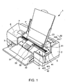
- Fig. 1 is a schematic view showing the construction of an ink jet printer 1 as a first embodiment of the droplet ejecting apparatus of the present invention.
- the terms "upper” and “lower” as used in the following description refer to the upper and lower side, respectively, in Fig.1. At first, explanation is made of the construction of the ink jet printer 1.
- the ink jet printer 1 shown in Fig. 1 is provided with a main body 2, having a tray 21 in the upper rear part thereof for accommodating recording paper P, an exit port 22 in the lower front part thereof for a recording paper P to exit, and an operation panel 7 in the upper surface thereof.
- the operation panel 7 is configured, for example, by a liquid crystal display, an organic EL display, or an LED lamp, to have a display part (not shown) for displaying an error message, etc. and an operating part (not shown) structured by various switches and the like.
- the main body 2 has, mainly, therein a printing device (printing means) 4 having character-printing means (movable body) 3 movable reciprocatively, a paper feed device (paper feed means) 5 for delivering the recording paper P sheet by sheet to the printing device 4, and a control section (control means) 6 for controlling the printing device 4 and the paper feed device 5.
- a printing device printing means
- movable body movable reciprocatively
- paper feed device paper feed means
- control section control means
- the paper feed device 5 feeds the recording paper P sheet by sheet intermittently.
- the recording paper P passes through a vicinity of the lower part of the character-printing means 3.
- the character-printing means 3 reciprocatively moves in a direction nearly orthogonal to the direction of feeding the recording paper P, thereby printing on the recording paper P.
- the reciprocative movement of the character-printing means 3 and the intermittent feed of recording paper P provides two-dimensional scanning in a main and a sub scanning direction, to effect a printing in an ink jet system.
- the printing device 4 has the character-printing means 3, a carriage motor 41 serving as a drive source for moving the character-printing means 3 in the main scanning direction, and a movement mechanism 42 receiving rotation of the carriage motor 41 and moving the character-printing means 3 reciprocatively.
- the character-printing means 3 has, in its lower part, a plurality of head units 35 having a multiplicity of nozzles 110 (see Fig. 3) corresponding to various kinds of ink, a plurality of ink cartridges (I/C) 31 for supplying ink to the head units 35, and a carriage 32 mounting the head units 35 and ink cartridges 31 thereon.
- a head unit 35 has a multiplicity of ink jet type recording heads (ink jet heads or droplet ejecting heads) 100 each having a nozzle 110, a vibration plate 121, an electrostatic actuator 120, a cavity 141, an ink supply port 142 and the like.
- the head unit 35 although shown as including an ink cartridge 31 in Fig. 1, is not limited to such a structure.
- the ink cartridges 31 may be separately fixed for supplying ink via tubes or the like to the head units 35.
- the provision with a plurality of ink jet heads 100 each structured by a nozzle 110, a vibration plate 121, an electrostatic actuator 120, a cavity 141, an ink supply port 142 and the like, is referred to as a head unit 35.
- the character-printing means 3 is provided with head units 35 corresponding to the respective colors.
- Fig. 1 shows four ink cartridges 31 corresponding to the four colors
- the character-printing means 3 may be structured further having three ink cartridges 31, e.g. in light cyan, light magenta, and dark yellow.
- the movement mechanism 42 has a carriage guide shaft 422 supported at its both ends by a frame (not shown) and a timing belt 421 extending in parallel with the carriage guide shaft 422.
- the carriage 32 is supported for reciprocative movement on the carriage guide shaft 422 and fixed on a part of the timing belt 421.
- the character-printing means 3 is guided along the carriage guide shaft 422 into reciprocative movement.
- ink is suitably ejected by nozzles 110 of the plurality of ink jet heads 100, in a manner corresponding to the image data (print data) for printing.
- printing is effected on the recording paper P.
- the paper feed device 5 has a paper feed motor 51 serving as its drive source and a paper feed roller 52 rotated by the operation of the paper feed motor 51.
- the paper feed roller 52 is structured by a driven roller 52a and a drive roller 52b that are placed on vertically opposite sides of a feed path of the recording paper P.
- the drive roller 52b is coupled to the paper feed motor 51. This allows for the paper feed roller 52 to deliver one by one a multiplicity of sheets of recording paper P toward the printing device 4.
- a paper feed cassette containing recording paper P may be removably attached.
- the control section 6 controls the printing device 4 and the paper feed device 5 depending upon the printing data inputted from a host computer 8, such as a personal computer (PC) or a digital camera (DC), thereby printing on the recording paper P.
- a host computer 8 such as a personal computer (PC) or a digital camera (DC)
- the control section 6 causes a display part of the operation panel 7 to display an error message or other message, or an LED lamp or the like to go on/flicker. Furthermore, it causes each part to carry out the corresponding process depending upon a depression signal of various switches inputted from the operating part.
- Fig. 2 is a block diagram schematically showing the major part of the ink jet printer of the present invention.
- the ink jet printer 1 has an interface (IF) 9 for receiving the printing data inputted from the host computer 8, the control section 6, the carriage motor 41, a carriage motor driver 43 for the carriage motor 41, the paper feed motor 51, a paper feed motor driver 53 for the paper feed motor 51, the head units 35 and head drivers 33 for the head units 35 (only one head unit and drive being shown), and an ejection-failure detecting means 10.
- the ejection-failure detecting means 10 and the head driver 33 will be detailed later.
- the control section 6 has a CPU (Central Processing Unit) 61 for executing various processes such as a printing process and an ejection-failure detecting process, an EEPROM (Electrically Erasable Programmable Read Only Memory) (storage means) 62 as one kind of non-volatile semiconductor memory for storing the printing data inputted through the IF 9 from the host computer 8 in a not-shown data storage area therein, a RAM (Random Access Memory) 63 for temporarily storing various data upon executing a an ejection-failure detecting process or temporarily expanding an application program such as for the printing process, and a PROM 64 as one kind of non-volatile semiconductor memory for storing a control program and the like to control various parts.
- the constituent elements of the control section 6 are electrically connected together through a not-shown bus.
- the character-printing means 3 has a plurality of head units 35 corresponding to the respective colors of ink.
- Each head unit 35 has a plurality of nozzles 110, and electrostatic actuators 120 corresponding to the respective nozzles 110.
- each head unit 35 has a plurality of ink jet heads 100 each having a set of a nozzle 110 and an electrostatic actuator 120.
- the head drivers 33 are each configured by the a drive circuit 18, for driving the electrostatic actuator 120 of each ink jet head 100 of the respective head unit 35 and controlling ink ejection timing, and a switch means 23 (see Fig. 16). The structure of the ink jet head 100 and electrostatic actuator 120 will be described later.
- the control section 6 is electrically connected with various sensors capable of detecting printing environments, including the remaining ink amount in a ink cartridge 31 and a position, temperature and humidity of the character-printing means 3 for example, though not shown.
- the control section 6, when acquiring printing data from the host computer 8 through the IF 9, stores the printing data in the EEPROM 62.
- the CPU 61 executes a predetermined process on the printing data, and outputs drive signals to the respective drivers 33, 43, 53 depending upon the processed data and the input data from the sensors. These drive signals, if inputted through the drivers 33, 43, 53, operate the electrostatic actuators 120 corresponding to the plurality of ink jet heads 100 of the respective head unit 35, the carriage motor 41 of the printing device 4, and the paper feed device 5, respectively. Due to this, printing operation is effected on the recording paper P.
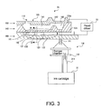
- FIG. 3 is a schematic sectional view of one ink jet head 100 of a head unit 35 shown in Fig. 2 (including a common part, such as the ink cartridge 31).
- Fig. 4 is an exploded perspective view showing a schematic structure of the head unit 35 corresponding to one color of ink.
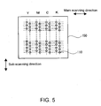
- Fig. 5 is a plan view showing one example of a nozzle surface of the head unit 35 having a plurality of the ink jet heads 100 shown in Fig. 3. Note that Figs. 3 and 4 show a vertical inversion relative to the state of usual use.
- Fig. 5 is a plan view of the ink jet head 100 shown in Fig. 3 as viewed from the above in the figure.
- the head unit 35 is connected to the ink cartridge 31 through an ink intake port 131, a damper chamber 130, and an ink supply tube 311.
- the damper chamber 130 has a damper 132 formed of rubber.
- the damper chamber 130 functions to absorb the swing and pressure change of ink during the reciprocative movement of the carriage 32. This can stably supply a predetermined amount of ink to the ink jet heads 100 of the respective head unit 35.
- the head unit 35 is a three-layer laminate, sandwiching a silicon substrate 140 by an upper nozzle plate 150 also made of silicon and a lower borosilicate glass substrate (glass substrate) 160 having a thermal expansion coefficient approximate to that of silicon.
- the central silicon substrate 140 is formed with a plurality of independent cavities (pressure chambers) 141 (seven cavities shown in Fig. 4), one reservoir (common ink chamber) 143, grooves respectively serving as the ink supply ports (orifices) 142 for communicating the reservoir 143 with the cavities 141.
- the grooves can be formed by etching the surface of the silicon substrate 140.
- the nozzle plate 150, the silicon substrate 140, and the glass substrate 160 are bonded together in this order to form the cavities 141, the reservoir 143, and the ink supply ports 142 by partitioning.
- cavities 141 are each formed in a rectangular form, the volume of which is to be varied by vibration (displacement) of a vibration plate 121.
- ink liquid material
- the nozzle plate 150 is formed with nozzles 110 in positions corresponding to the tips of the cavities 141 and in communication with the respective cavities 141.
- An ink intake port 131, communicating with the reservoir 143, is formed through the glass substrate 160 in an area where the reservoir 143 is located.
- Ink is passed from the ink cartridge 31 via the ink supply tube 311 and damper chamber 130 to the ink intake port 131 and supplied to the reservoir 143.
- the ink supplied to the reservoir 143 is supplied to the individual cavities 141 through the respective ink supply ports 142.
- the cavities 141 are partitioned by the nozzle plate 150, sidewalls (partition walls) 144, and bottom wall 121.
- the bottom wall 121 of each cavity 141 is formed as a thin wall.
- the bottom wall 121 is structured to function as a vibration plate (diaphragm) to elastically deform (elastically displace) outward with respect to its plane (in the thickness direction), i.e., in the vertical direction of Fig. 3. Accordingly, the part of bottom wall 121 may be referred to as the vibration plate 121 in explanation, for the convenience of explanation (i.e., reference numeral 121 is hereinafter used for the both of "bottom wall” and "vibration plate”).
- shallow recesses 161 are respectively formed in positions corresponding to the cavities 141 of the silicon substrate 140.
- the bottom wall 121 of the cavity 141 is opposed, with predetermined spacing, to the surface of an opposite wall 162 of the glass substrate 160 formed with the recess 161.
- a predetermined thickness e.g., about 0.2 microns
- the recess 161 can be formed by etching, for example.
- the vibration plate 121 of the cavity 141 constitutes a part of common electrode 124 on the side of cavities 141 for storing charges depending upon a drive signal supplied from the head driver 33.
- the vibration plate 121 serves as one of two opposed electrodes (capacitor's opposed electrode) of the electrostatic actuator 120.
- the segment electrodes 122 facing the common electrode 124 are formed in a manner to opposed the bottom walls 121 of the cavities 141, respectively.
- the surface of the bottom wall 121 facing the glass substrate is covered with an insulation layer 123 of silicon oxide film (SiO 2 ).
- the bottom wall 121, and the corresponding segment electrode 122 form opposed electrodes through this insulation layer 123 and the air gap in the recess 161. Accordingly, the major part of the electrostatic actuator 120 is constituted by the vibration plate 121, the segment electrode 122, and the insulation layer 123 and air gap between them.
- the head driver 33 including the drive circuit 18 for applying drive voltages between the opposed electrodes, charges and discharges the respective capacitor formed by the opposed electrodes according to a printing signal (printing data) inputted from the control section 6.
- the head driver (voltage applying means) 33 has one output terminal connected to the individual segment electrode 122 and another output terminal connected to an input terminal 124a of the common electrode 124 formed on the silicon substrate 140.
- the silicon substrate 140 is doped with an impurity and possesses a conductivity by itself, voltage can be supplied from the input terminal 124a of the common electrode 124 to the common electrode 124 on the bottom wall 121.
- a thin film of a conductive material, such as gold or copper, may be formed on one surface of the silicon substrate 140.
- a voltage (charge) can be applied at low electric resistance to the common electrode 124.
- the thin film may be formed by evaporation, sputtering or the like.
- a conductor film to be used as an electrode in the anode bonding is formed on the surface of the silicon substrate 140 on a side forming a flow passage (upper side of the silicon substrate 140 shown in Fig. 3).
- the conductor film, as it is, is used as the input terminal 124a of the common electrode 124.
- the input terminal 124a of the common electrode 124 may be omitted and the bonding of the silicon substrate 140 to the glass substrate 160 is not limited to anode bonding.
- the head unit 35 has the nozzle plate 150 formed with the plurality of nozzles 110 corresponding to the plurality of ink jet heads 100; the silicon substrate (ink chamber substrate) 140 formed with the plurality of cavities 141, the plurality of ink supply ports 142, and one reservoir 143; and the insulation layer 123. These are accommodated in a base body 170 including the glass substrate 160.
- the base body 170 is structured of a resin material in various kinds, a metal material in various kinds or the like.
- the silicon substrate 140 is fixed and supported on the base body 170.
- the plurality of nozzles 110 formed in the nozzle plate 150 are arranged straight nearly in parallel with the reservoir 143 for easy representation in Fig. 4.
- the arrangement pattern of nozzles 110 is not limited to this configuration, and usually the nozzles are arranged displaced relative to each other as shown in Fig. 5.
- the pitch of the nozzles 110 can be suitably set in accordance with printing resolution (dpi).
- Fig. 5 shows an arrangement pattern of nozzles 110 for the case of four colors of ink.
- Fig. 6A to C are sectional view along line III-III of Fig. 3 illustrating different states during input of a drive signal.
- a drive voltage is applied from the head driver 33 between the opposed electrodes, a Coulomb force occurs between the electrodes.
- the vibration plate 121 deflects toward the segment electrode 122 compared with its initial state (Fig. 6A), to expand the volume of cavity 141 (Fig. 6B).
- the vibration plate 121 restores towards the initial state by its elastic restoration force and moves up beyond its initial state.
- the cavity 141 suddenly contracts in volume (Fig. 6C).
- part of the ink in the cavity 141 is ejected as ink an droplet from the ink nozzle 110 communicating with the cavity 141 due to compression pressure generated in the cavity 141.
- the vibration plate 121 of the cavity 141 is in damped vibration before the next drive signal is applied to again eject an ink droplet by the series of operations illustrated in Fig. 6A to C.
- the damped vibration is also referred to as residual vibration.
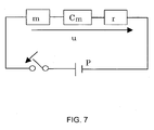
- the residual vibration of the vibration plate 121 has assumably an eigen-frequency determined by an acoustic resistance r due to the shape of the nozzle 110 and ink supply port 142, or ink viscosity and the like, an inertance m due to the ink weight in the flow passage, and a compliance Cm of the vibration plate 121.
- Fig. 7 is an equivalent circuit diagram showing the computation model on a simple harmonic vibration wherein the residual vibration is assumed of the vibration plate 121.
- the computation model of the residual vibration of the vibration plate 121 can be represented by acoustic pressure P, inertance m, compliance Cm, and acoustic resistance r, noted above.
- a volume velocity u a step response upon delivering an acoustic pressure P to the circuit of Fig. 7, the following equation is obtained.
- Fig. 8 is a graph showing the relationship between the experimental values of residual vibration of the vibration plate 121 and the computation values. As can be seen from the graph of Fig. 8, the two waveforms of experimental and computation values are nearly in agreement.
- a droplet ejection failure occurs (simply referred to a "ejection failure” hereinafter).
- the cause of such ejection failure includes (1) an air bubble in the ink in the cavity 141, (2) dried/thickened (adhered) ink at or around the nozzle 110, and (3) paper powder adhering to the vicinity of nozzle 110 exit. These causes will simply be referred to as “air bubble”, “dried liquid” and “paper powder”, respectively, in the following.
- the acoustic resistance r and/or the inertance m are adjusted on the basis of the comparison result shown in Fig. 8 such that the computation and experimental values of residual vibration of the vibration plate 121 match (are nearly in agreement) for each cause the ejection failure.
- consideration herein is made of the three kinds, i.e., air bubble, dried liquid, and paper powder.
- Fig. 9 is a concept view at or around the nozzle 110 where an air bubble B is in the cavity 141. As shown in Fig. 9, the air bubble B is assumed to be on a wall surface of the cavity 141 (in Fig. 9, shown is the case, as an example, of the position the air bubble B at or around the nozzle 110).
- the air bubble B when the air bubble B is in the cavity 141, there is considered a reduction in the total amount of ink the cavity 141, to lower the inertance m. It can be considered that because the air bubble B is on the wall surface of the cavity 141, the nozzle 110 appears to be increased in diameter by an amount corresponding to the diameter of the air bubble B thus lowering the acoustic resistance r.
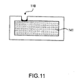
- Fig. 11 is a concept view of the nozzle 110 and its surrounding in the case that the ink nearby the nozzle 110 in Fig. 3 has dried into adhesion.
- the ink at or around the nozzle 110 dries into adhesion, the ink within the cavity 141 is in a status confined within the cavity 141. In this manner, it can be considered that, where the ink nearby the nozzle 110 is dried and thickened, there is an increase of acoustic resistance r.
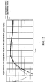
- the experimental values shown in Fig. 12 are on the measurement of residual vibration of the vibration plate 121 performed after the head unit 35 was left uncovered for several days, i.e., not covered with a not-shown cap, to cause drying/thickening of ink at or around the nozzle 110 (ink adhesion).
- the frequency is extremely low as compared to that during normal ejection and obtained is a characteristic residual vibration waveform having an excessively damped residual vibration. This is because, after ink flows in the cavity 141 from the reservoir 143 due to downward attraction in Fig.
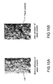
- Fig. 13 is a concept view of the nozzle 110 and its vicinity in the case paper powder adheres to a vicinity of the nozzle exit of Fig. 3. As shown in Fig. 13, in the case that paper powder adheres to a vicinity of the exit of nozzle 110, ink possibly soaks out from the inside of the cavity 141 through the paper powder and ink cannot be ejected from the nozzle 110.
- FIG. 15 are photographs showing the state of the nozzle 110 before and after paper powder adhesion. It is possible to find out, from Fig. 15B, that, if a paper powder adheres to a vicinity of the nozzle 110, ink soaks out along the paper powder.
- the damped-vibration frequency is lower as compared to the case of normal ejection of ink droplets.
- comparison can be made with a predetermined threshold frequency, period or phase of the damped vibration. Otherwise, they can be detected from a damping factor in frequency or amplitude change of the residual vibration (damped vibration).
- the cause of ejection failure can be detected by comparing the respective residual vibration frequency with that of normal ejection.
- Fig. 16 is a schematic block diagram of the ejection-failure detecting means 10 shown in Fig. 2.
- the ejection-failure detecting means 10 of the present invention has a residual vibration detecting means 16 configured by an oscillation circuit 11, an FN (frequency/voltage) converting circuit 12, and a waveform shaping circuit 15; a measuring means 17 for measuring a period or frequency from the residual vibration waveform data detected by the residual vibration detecting means 16; and a determining means 20 for determining an ejection failure of the ink jet head 100 depending upon a frequency or the like measured by the measuring means 17.
- the residual vibration detecting means 16 causes the oscillation circuit 11 to oscillate based on the residual vibration of the vibration plate 121 of the electrostatic actuator 120. From this oscillation frequency, a vibration waveform is formed in the F/V converting circuit 12 and waveform shaping circuit 15, and then detection is carried out. Then, the measuring means 17 measures a frequency and the like of the residual vibration depending upon a detected vibration waveform.
- the determining means 20 detects and determines an ejection failure on the ink jet head 100 of the head unit 35 depending upon the measured residual vibration period or the like (residual vibration pattern). In the following, explained are the constituent elements of the ejection-failure detecting means 10.
- Fig. 17 is a concept figure of the electrostatic actuator 120 of Fig. 3 made as a parallel plate capacitor
- Fig. 18 is a circuit diagram of the oscillation circuit 11 including as capacitor the electrostatic actuator 120 of Fig. 3.
- the oscillation circuit 11 shown in Fig. 18 is a CR oscillation circuit utilizing a Schmitt-trigger hysteresis characteristic
- the invention is not limited to such a CR oscillation circuit but can use any oscillation circuit that can use the capacitance component (capacitor C) of an actuator (including a vibration plate).
- the oscillation circuit 11 may be in a configuration utilizing an LC oscillation circuit, for example. This embodiment is explained with the example using the Schmitt-trigger inverter, a CR oscillation circuit may be configured using three stages of inverters.
- the electrostatic actuator 120 is structured with opposed electrodes formed by the vibration plate 121 and the segment electrode 122 spaced from each other by a very gap.
- This electrostatic actuator 120 can be considered as a parallel plate capacitor as shown in Fig. 17.
- C(X) ⁇ 0 ⁇ ⁇ r S g-x (F)
- x in Equation (4) denotes a displacing amount from a reference position of the vibration plate 121 caused by residual vibration of the vibration plate 121.
- the capacitance C(x) increases as the gap length g (gap length g - displacing amount x) decreases while, conversely, the capacitance C(x) decreases as the gap length g (gap length g - displacing amount x) increases.
- the capacitance C(x) is inversely proportional to (gap length g - displacing amount x) (gap length g when x is 0).
- the electrostatic actuator 120 is increased in density and smaller in size. This reduces the surface area S of the vibration plate 121 of the ink jet head 100, structuring a smaller electrostatic actuator 120. Furthermore, the gap length g of the electrostatic actuator 120, to be varied by residual vibration due to ink droplet ejection, is nearly 10% of the initial gap g 0 . Consequently, the capacitance change amount on the electrostatic actuator 120 is a quite small value, as can be seen from Equation (4).
- the method is that an oscillation circuit as in Fig. 18 is configured based on the capacitance of the electrostatic actuator 120, to analyze the frequency (period) of residual vibration on the basis of an oscillation signal.
- the oscillation circuit 11 shown in Fig. 18 is configured by a capacitor (C) constituted by the electrostatic actuator 120, a Schmitt trigger inverter 111, and resistance element (R) 112.
- the capacitor C is charged through the resistance element 112.
- the charge voltage (potential difference between the vibration plate 121 and the segment electrode 122) of the capacitor C reaches an input threshold voltage V T + of the Schmitt trigger inverter 111
- the output signal of the Schmitt trigger inverter 111 inverts to Low level.
- the output signal of the Schmitt trigger inverter 111 becomes Low level
- the charge of the capacitor C charged through the resistance element 112 is discharged.
- the output signal of the Schmitt trigger inverter 111 again inverts to High level. From then on, these oscillation operations are repeated.
- the oscillation frequency of the oscillation circuit 11 In order to detect the capacitance change against time of the capacitor C in each of the ejection failure causes (air bubble, dried liquid, and paper powder) as well as in case of normal ejection, there is a need for setting the oscillation frequency of the oscillation circuit 11 that can detect a frequency in case of air bubble (see Fig. 10) highest in residual vibration frequency. For this reason, the oscillation frequency of the oscillation circuit 11 must be given several times to several tens times the residual vibration frequency to be detected, i.e., higher one figure or more than the frequency in case of air bubble. In this case, preferably, because the residual vibration frequency in case of air bubble is higher than that in case of normal ejection, setting is at the oscillation frequency for detecting the residual vibration frequency in case of air bubble.
- a CR time constant of the oscillation circuit 11 is set depending upon the oscillation frequency. In this manner, by setting the oscillation frequency of the oscillation circuit 11 high, it is possible to detect a more correct residual vibration waveform depending upon a slight change in this oscillation frequency.
- Fig. 19 is a circuit diagram of the FN converting circuit 12 of the ejection-failure detecting means 10 shown in Fig. 16.
- the FN converting circuit 12 is configured by three switches SW1, SW2, and SW3; two capacitors C1 and C2; a resistance element R1; a constant-current source 13 for outputting a constant current Is; and a buffer 14.
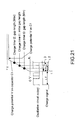
- the operation of the FN converting circuit 12 is explained using the timing chart of Fig. 20 and the graph of Fig. 21.
- the charge signal can be generated such that it is set with a fixed time tr from a rise edge of an oscillation pulse of the oscillation circuit 11 and assumes a High level for the fixed time tr.
- the hold signal is generated such that it rises synchronously with a rise edge of the charge signal and held in High level for a predetermined fixed time and then falls to Low level.
- the clear signal is generated such that it rises synchronously with a fall edge of the hold signal and held in High level for a predetermined fixed time and then falls to Low level.
- the hold signal and the clear signal may respectively have one pulse before a next rise in the output signal of the oscillation circuit 11, thus not limited to the rise and fall edges as above.
- the fixed time tr is adjusted based on the period of an oscillation pulse as it occurs when the capacitance C of the electrostatic actuator 120 is that obtained with the initial gap length go, and set such that the charge potential after the charge time t1 is nearly 1/2 of a certain charge range of C1, the charge range being defined by a lower and an upper voltage value of the capacitor C1 and set to be within the input voltage range of buffer 14.
- the constant current Is of the constant current source 13 By setting the constant current Is of the constant current source 13 as high as possible within the charge range, it is possible to detect, with high sensitivity, a slight capacitance change of the capacitor constituted by the electrostatic actuator 120, i.e., to achieve the maximum dynamic range for the amplitude of the detection waveform within the charge range of C1. Thus, it is possible to detect a slight change of the vibration plate 121 of the electrostatic actuator 120.
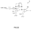
- Fig. 22 is a circuit diagram showing a circuit configuration of the waveform shaping circuit 15 shown in Fig. 16.
- This waveform shaping circuit 15 is to output a residual vibration waveform as a rectangular wave to the determining means 20.
- the waveform shaping circuit 15 is configured with two capacitors C3 (DC component removing means) and C4; two resistance elements R2 and R3; two DC voltage sources Vref1 and Vref2; an amplifier (operational amplifier) 151; and a comparator 152.
- configuration may be made to output, as it is, a wave height value detected in a waveform shaping process on the residual vibration waveform, thereby measuring an amplitude of the residual vibration waveform.
- the output of the buffer 14 of the F/V converting circuit 12 contains a DC component based on the capacitance component corresponding to the initial gap go of the electrostatic actuator 120. Because the DC component varies between the ink jet heads 100, the capacitor C3 removes a DC component in the output signal of the buffer 14, and outputs only an AC component of residual vibration to an inverted input terminal of the operational amplifier 151.
- the operational amplifier 151 inverts and amplifies the AC component of the output signal of the buffer 14 of the F/V converting circuit 12 and is configured as a low pass filter for removing the higher band of the output signal. Incidentally, this operational amplifier 151 is assumed a single power source circuit.
- the operational amplifier 151 configures an inverting amplifier with two resistance elements R2 and R3, to amplify an inputted residual vibration (alternating current component) -R3/R2 times.
- the operational amplifier 151 Because of single power source operation of the operational amplifier 151, outputted is an amplified residual vibration waveform of the vibration plate 121 vibrating about a potential set by the DC voltage source Vref1 connected to the non-inverted input terminal thereof.
- the DC voltage source Vref1 is set at about a half of the voltage range the operational amplifier 151 is operable on a single power source. Furthermore, this operational amplifier 151 configures a low pass filter having a cutoff frequency 1/(2 ⁇ ⁇ C4 ⁇ R3) based on two capacitors C3 and C4.
- the comparison result is outputted as a rectangular wave from the waveform shaping circuit 15.
- the DC voltage source Vref2 may use also the other DC voltage source Vref1.
- the FN converting circuit 12 shown in Fig. 19 operates on the basis of the charge signal, clear signal, and hold signal generated as in the above.
- the vibration plate 121 of the electrostatic actuator 120 is attracted toward the segment electrode 122 as shown in Fig. 6B and rapidly contracts toward the above in Fig. 6 synchronously with a fall edge of the drive signal (see Fig. 6C).
- the drive/detection switching signal for switching over between the drive circuit 18 and the ejection-failure detecting means 10 becomes High in level.
- This drive/detection switching signal in a drive-halt period of the corresponding ink jet head 100, is held High in level and becomes Low in level before the next drive signal is inputted.
- the oscillation circuit 11 of Fig. 18 is in oscillation while changing its oscillation frequency correspondingly to the residual vibration of the vibration plate 121 of the electrostatic actuator 120.
- the charge signal is held at High level until the lapse of a fixed time tr previously set, such that the residual vibration waveform does not exceed a chargeable range of the capacitor C1, at the fall edge of the drive signal, i.e., a rise edge of the output signal of the oscillation circuit 11.
- the switch SW1 is in an off state.
- the switch SW1 When the fixed time tr elapses and the charge signal becomes Low in level, the switch SW1 is turned on synchronously with the fall edge of the charge signal (see Fig. 19). Then, the constant-current source 13 and the capacitor C1 are connected together, and the capacitor C1 is charged with an inclination Is/C1 as noted above. The capacitor C1 is being charged in the time period the charge signal is at a Low level, i.e., in the duration before assuming High level synchronously with a rise edge of the next pulse of the output signal of the oscillation circuit 11.
- the switch SW1 When the charge signal becomes High level, the switch SW1 turns off (opens), and the constant-current source 13 and the capacitor C1 are disconnected. Thereupon, the capacitor C1 is held with the potential charged during the Low level time period t1 of the charge signal (i.e., ideally Is ⁇ t1/C1(V)). In this state, when the hold signal becomes High level, the switch SW2 turns on (see Fig. 19), to connect the capacitor C1 and the capacitor C2 through the resistance element R1. After connecting the switch SW2, charging and discharging is mutually made by the charge potential difference between the two capacitors, C1 and C2. Charge is moved from the capacitor C1 to the capacitor C2 such that the potential difference of capacitor, C1 and that of C2, become nearly the same.
- the capacitance of the capacitor C2 is set approximately one-tenth or less the capacitance of the capacitor C1. Consequently, the amount of the charge, to be moved for charging C2 and leveling the potential difference between the two capacitors, C1 and C2, is one-tenth or less of the charge stored on the capacitor C1. Accordingly, even after charge movement from the capacitor C1 to the capacitor C2, the potential difference of the capacitor C1 is not greatly changed (not greatly lowered).
- a primary low pass filter is configured by a resistance element R1 and capacitor C2 in order not to cause abrupt rise of charge potential due to the inductance of the wiring of the F/V converting circuit 12 when the capacitor C2 is charged.
- the hold signal becomes Low level.
- the capacitor C1 is disconnected from the capacitor C2.
- the switch SW3 turns off into standby until the upper electrode (in Fig. 19) of the capacitor C1 is disconnected from the ground GND and the next charge signal is inputted.
- the potential held on the capacitor C2 is updated in each timing of charge signal rise, i.e., each timing of completion of charging to the capacitor C2, and outputted as a residual vibration waveform of the vibration plate 121 to the waveform shaping circuit 15 of Fig. 22 through the buffer 14. Consequently, in case the capacitance (in this case, capacitance variation width due to residual vibration must be considered) of the electrostatic actuator 120 and the resistance value of the resistance element 112 are set in a manner increasing the oscillation frequency of the oscillation circuit 11, the potential (output of the buffer 14) step of capacitor C2 shown in the timing chart of Fig. 20 is further detailed, making it possible to detect a change in time of the capacitance due to the residual vibration of the vibration plate 121 in more detail.
- the potential held on the capacitor C2 in the predetermined timing is outputted to the waveform shaping circuit 15 through the buffer 14.
- the DC component of a voltage signal (potential of the capacitor C2, in the timing chart of Fig. 20) inputted from the buffer 14 is removed by the capacitor C3, and the AC (alternating current) component is inputted to the inverted input terminal of the operational amplifier 151 through the resistance element R2.
- the inputted AC component of residual vibration is inversion-amplified by the operational amplifier 151 and outputted to one input terminal of the comparator 152.
- the comparator 152 compares the potential (reference voltage) previously set by the DC voltage source Vref2 and the potential of residual vibration waveform (AC component), to output a rectangular wave (output of the comparator circuit in the timing chart of Fig. 20).
- Fig. 23 is a block diagram showing the outline of the switch over means 23 between the drive circuit 18 and the ejection-failure detecting means 10.
- the drive circuit 18 within the head driver 33 shown in Fig. 16 is illustrated as a drive circuit for the ink jet head 100.
- the ejection-failure detection process of the present invention is executed between drive signals for the ink jet head 100, i.e., in drive-halt period.
- the switch means 23 is first connected to the drive circuit 18 side in order to drive the electrostatic actuator 120.
- a drive signal voltage signal
- the electrostatic actuator 120 is driven.
- the vibration plate 121 is attracted toward the segment electrode 122 and, when the applied voltage becomes zero, it rapidly displaces in a direction away from the segment electrode 122 thus starting vibration (residual vibration).
- an ink droplet is ejected from the nozzle 110 of the ink jet head 100.
- a drive/detection switching signal (see the timing chart of Fig. 20) is inputted synchronously with the fall edge thereof to the switch means 23.
- the switch means 23 is switched from the drive circuit 18 over to the ejection-failure detecting means (detecting circuit) 10.
- the electrostatic actuator 120 (utilized as a capacitor for the oscillation circuit 11) is connected to the ejection-failure detecting means 10.
- the ejection-failure detecting means 10 carries out a detecting process of ejection failure as noted before, to digitize the residual vibration waveform data (rectangular wave data) of the vibration plate 121 outputted from the comparator 152 of the waveform shaping circuit 15 into a period or amplitude of residual vibration waveform by the measuring means 17.
- the measuring means 17 measures a particular vibration period from the residual vibration waveform data, and outputs the result of the measuring (numeric value) to the determining means 20.
- the measuring means 17 counts the pulses of a reference signal (predetermined frequency) by using a not-shown counter in order to measure the time of from the first rise edge to the next rise edge of an output signal waveform (rectangular wave) of the comparator 152, and measures the period (particular vibration period) of residual vibration from the count value.
- the measuring means 17 may measure the time from the first rise edge to the next fall edge (i.e., a half period), to output a time twice the measured time as the residual vibration period to the determining means 20.
- the residual vibration period thus obtained is assumed to be Tw.
- the determining means 20 determines a presence or absence of an ejection failure, the cause of the ejection failure, if any, a comparison deviation value and so on depending upon a particular vibration period (measuring result) or the like measured by the measuring means 17 and outputs the determination result to the control section 6.
- the control section 6 saves the determination result in a preset storage domain of the EEPROM (storage means) 62. Then, a drive/detection switching signal is again inputted to the switch means 23 at the timing the next drive signal is inputted from the drive circuit 18, to connect the drive circuit 18 to the electrostatic actuator 120.
- the drive circuit 18, because maintaining the ground (GND) level if drive voltage is once applied, makes a switching as in the above by the switch means 23 (see the timing chart of Fig. 20). Due to this, it is possible to correctly detect a residual vibration waveform of the vibration plate 121 of the electrostatic actuator 120 without being affected by the outside disturbance from such as the drive circuit 18.
- the residual vibration waveform data is not limited to those of rectangular waves output by the comparator 152.
- the residual vibration amplitude data outputted from the operational amplifier 151 may be digitized at all times by the measuring means 17 for A/D conversion, without making a comparison process by the comparator 152.
- the determining means 20 may determine a presence or absence of election failure, to store the determination result in the storage means 62.
- the present invention can detect an ejection failure without effect upon driving the ink jet head 100, because of detecting the residual vibration of the vibration plate 121 by effectively utilizing the standby time. Namely, it is possible to carry out an ejection-failure detection process for the nozzle 110 of the ink jet head 100 without lowering the throughput on the ink jet printer 1.
- the frequency increases as compared with the residual vibration waveform of the vibration plate 121 in normal ejection state, to have a period shorter than the period of residual vibration during normal ejection.
- the ink at or around the nozzle 110 is thickened or adhered due to drying (dried liquid)
- the residual vibration is excessively attenuated; because the frequency is considerably lower as compared to the residual vibration waveform in normal ejection, the period is considerably longer than the period of residual vibration in normal ejection.
- the residual vibration has a frequency lower than the residual vibration frequency in normal ejection but higher than the residual vibration frequency with dried ink; consequently, this period is longer than the period of residual vibration in normal ejection but shorter than the period of residual vibration in case of dried ink.
- a predetermined range Tr defined by upper limit Tru and lower limit Trl
- a predetermined threshold T1 for distinguishing between a residual vibration period in the case of paper powder and a residual vibration period in the case of dried liquid
- the determining means 20 determines whether the period Tw of a residual vibration waveform detected by the above ejection-failure detecting process is within a predetermined range or not, and whether it is longer than a predetermined threshold or not, thereby determining the cause of ejection failure.
- Fig. 24 is a flowchart showing an ejection-failure detection/determination process of the invention.
- the printing data for printing (or may be ejection data in a flushing operation) is inputted from the host computer 8 to the control section 6 through the interface (IF) 9 (Fig. 2), the ejection failure detecting process is executed in predetermined timing.
- the flowchart shown in Fig. 24 shows an ejection-failure detecting process corresponding to one ink jet head 100, i.e., an ejection operation on one nozzle 110 to simplify the explanation.
- a drive signal corresponding to printing data is inputted from the drive circuit 18 of the head driver 33. Due to this, a drive signal (voltage signal) is applied between the respective electrodes of the electrostatic actuator 120, depending upon the timing of the drive signal as shown in the timing chart of Fig. 20 (step S101).
- the control section 6 determines whether the ink jet head 100 which was to eject an ink droplet is in a drive-halt period or not, depending upon a drive/detection switching signal (step S102).
- the drive/detection switching signal becomes High in level synchronously with a fall edge of the drive signal (see Fig. 20), and inputted from the control section 6 to the switch means 23.
- the electrostatic actuator 120 i.e., the capacitor of the oscillation circuit 11
- the electrostatic actuator 120 is disconnected from the drive circuit 18 by the switch means 23, and connected to the ejection-failure detecting means 10 (detecting circuit), i.e., oscillation circuit 11 of the residual vibration detecting means 16 (step S103).
- detecting circuit i.e., oscillation circuit 11 of the residual vibration detecting means 16
- step S104 a residual vibration detecting process
- the measuring means 17 measures a predetermined numerical value from the residual vibration waveform data detected in the residual vibration detecting process (step S105). As described above, the measuring means 17 measures a period of the residual vibration from the residual vibration waveform data.
- the determining means 20 carries out an ejection-failure detecting process depending upon the measurement result by the measuring means (step S106).
- the determination result is saved in a predetermined storage domain of the EEPROM (storage means) 62 of the control section 6 (step S107).
- step S108 it is determined whether the ink jet head 100 is in a drive period or not. Namely, it is determined whether or not the drive-halt period is terminated and the next drive signal is inputted. The process is in standby in this step S108 until the next drive signal is inputted.
- the switch means 23 switches the connection with the electrostatic actuator 120 from the ejection-failure detecting means (detecting circuit) 10 over to the drive circuit 18 (step S109), thus ending the ejection-failure detecting process.
- the flowchart shown in Fig. 24 explained the case the measuring means 17 measures a period from the residual vibration waveform detected by the residual vibration detecting process (residual vibration detecting means 16).
- the present invention is not limited to such cases.
- the measuring means 17 may make a measurement on a phase difference and amplitude of a residual vibration waveform from the residual vibration waveform data detected in the residual vibration detecting process.
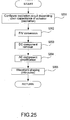
- Fig. 25 is a flowchart showing a residual vibration detecting process of the invention.
- the oscillation circuit 11 forms a CR oscillation circuit, to make an oscillation depending upon a capacitance change of the electrostatic actuator 120 (residual vibration of the vibration plate 121 of the electrostatic actuator 120) (step S201).
- a charge signal, a hold signal, and a clear signal are generated in the F/V converting circuit 12 depending upon an output signal (pulse signal) of the oscillation circuit 11.
- the F/V converting circuit 12 carries out an F/V conversion process of converting a frequency of output signal of the oscillation circuit 11 into a voltage (step S202); a residual vibration waveform data of the vibration plate 121 is outputted from the F/V converting circuit 12.
- the residual vibration waveform data outputted from the F/V converting circuit 12 has its DC component removed by the capacitor C3 of the waveform shaping circuit 15 (step S203).
- the operational amplifier 151 amplifies the residual vibration waveform (AC component) (step S204).
- the residual vibration waveform data after amplified, is waveform-shaped by a predetermined process and made into a pulse waveform (step S205).
- the comparator 152 compares a voltage value (predetermined voltage value) set by the DC voltage source Vref2 and the output voltage of the operational amplifier 151.
- the comparator 152 outputs a binary waveform (rectangular wave) depending upon the comparison result.
- the output signal of the comparator 152 in other words, the output signal of the residual vibration detecting means 16, is outputted to the measuring means 17 in order to carry out an ejection-failure determining process, thus ending the residual vibration detecting process.
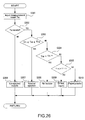
- Fig. 26 is a flowchart showing an ejection-failure determining process to be executed by the control section 6 and determining means 20 of the present invention.
- the determining means 20 determines, depending upon the measurement data (measurement result) such as the period measured by the measuring means 17, whether an ink droplet has been normally ejected from the relevant ink jet head 100 or not. In the case of not normal ejection, i.e., in the case of ejection failure, determination is made as to what the cause thereof is.
- the control section 6 outputs to the determining means 20 the predetermined range Tr of the period of residual vibration and a predetermined threshold T1 of the period of residual vibration saved in the EEPROM 62.
- the predetermined range Tr of the period of residual vibration is to provide an allowable range (from lower limit Trl to upper limit Tru) for determination of the residual vibration period in normal ejection.
- the result of measurement, by the measuring means 17 in the step S105 of Fig. 24, is inputted to the determining means 20 (step S301).
- the measurement result is a residual vibration period Tw of the vibration plate 121.
- step S302 the determining means 20 determines whether or not there exists a residual vibration period Tw, i.e., whether or not residual vibration waveform data has been obtained by the ejection-failure detecting means 10.
- the determining means 20 determines that the nozzle 110 of the ink jet head 100 is a non-ejecting nozzle having not ejected an ink droplet in the ejection-failure detecting process (step S306).
- the determining means 20 subsequently in step S303 determines whether the period Tw is within the predetermined range Tr to be recognized as a period in normal ejection.
- the determining means 20 determines that the nozzle 110 of the ink jet head 100 has normally ejected an ink droplet (normal ejection) (step S307).
- the determining means 20 subsequently in step S304 determines whether the residual vibration period Tw is shorter than the lower limit Trl or not.
- the determining means 20 determines that an air bubble is in the cavity 141 of the ink jet head 100 (air bubble) (step S308).
- the determining means 20 When it is determined that the residual vibration period Tw is longer than the upper limit Tru, the determining means 20 subsequently determines whether the residual vibration period Tw is longer than the predetermined threshold T1 or not (step S305). When it is determined that the residual vibration period Tw is longer than the predetermined threshold T1, it can be considered that the residual vibration is excessively attenuated. Thus, the determining means 20 determines that the ink at or around the nozzle 110 of the ink jet head 100 is thickened (dried) by drying (step S309).
- the residual vibration period Tw is a value in a range satisfying Tru ⁇ Tw ⁇ T1.
- the determining means 20 thus determines that paper powder adheres in the vicinity of the nozzle exit of the ink jet head 100 (paper powder) (step S310).
- the determining means 20 determines either normal ejection or the cause of an ejection failure of the ink jet head 100 under consideration (steps S306 - S310), the determination result is outputted to the control section 6, thus ending the ejection-failure determining process.
- the electrostatic actuator 120 is driven to thereby make an operation of ejecting liquid as a droplet from the ink jet head 100.
- the residual vibration detecting means 16 detects a residual vibration of the vibration plate 121 displaced by the electrostatic actuator 120.
- the measuring means 17 measures a vibration pattern (e.g., residual vibration waveform period, amplitude and the like) of residual vibration of the vibration plate 121 detected by the residual vibration detecting means 16. Based on the measurement result, the determining means 20 determines whether a droplet has been normally ejected or not ejected (ejection failure) and, when an ejection failure occurred, what the cause thereof is.
- the droplet ejecting apparatus and ejection failure detecting/determining method for a droplet ejecting head of this invention does not require the other parts (e.g., optical dot-missing detecting device) as compared to the droplet ejection head/apparatus using the conventional ejection failure detecting method (e.g., optical detecting method). Accordingly, it is possible to detect an ejection failure without increasing the size of the droplet ejection head. Furthermore, it is possible to keep low the manufacturing cost of the droplet ejecting apparatus for detecting an ejection failure (ejection failure).
- the residual vibration of the vibration plate after ejection is used to detect an ejection failure
- an ejection failure can be detected even in the course of printing operation. Accordingly, even in case the ejection-failure detecting/determining method of the present invention is carried out during printing operation, there is no possibility of lowering or worsening the throughput of the droplet electing apparatus.
- the droplet ejecting apparatus of the invention can determine the cause of an ejection failure that is impossible to determine by a conventional apparatus for detecting an ejection failure, such as an optical detecting apparatus. Due to this, it is possible to select and carry out a suitable recovery process on the cause, as required.
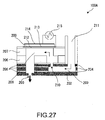
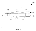
- FIGs. 27 to 30 are sectional views respectively showing the outlines of the other structural examples of the ink jet head 100.
- An ink jet head 100A shown in Fig. 27 has a vibration plate 212 to be vibrated by means of a piezoelectric element 200, to eject the ink (liquid) from a cavity 208 through a nozzle 203.
- a stainless steel nozzle plate 202, formed with nozzles (ports) 203, is bonded to a stainless steel metal plate 204 through an adhesive film 205, on which a similar stainless steel metal plate 204 is further bonded through an adhesive film 205.
- a communication-port-forming plate 206 and a cavity plate 207 are bonded thereon.
- the nozzle plate 202, the metal plate 204, the adhesive plate 205, the communication-port-forming plate 206, and the cavity plate 207 are respectively formed in predetermined shapes (shapes to form a recess). By superposing these plates, the cavity 208 and a reservoir 209 are formed. The cavity 208 and the reservoir 209 are in communication through an ink supply port 210. The reservoir 209 communicates with an ink intake port 211.
- the vibration plate 212 is arranged over an upper-surface opening of the cavity plate 207. This vibration plate 212 is bonded with a piezoelectric element 200 through a lower electrode 213. An upper electrode 214 is bonded on the piezoelectric element 200 oppositely to the lower electrode 213. A head drive 215 has a drive circuit for generating a drive voltage waveform. By applying the drive voltage waveform to the upper electrode 214 and the lower electrode 213, the piezoelectric element 200 is driven to thereby drive the vibration plate 212 bonded thereto. Vibrating the vibration plate 212 causes a volume (pressure within the cavity) change in the cavity 208, to eject an ink droplet from the ink (liquid) filling the cavity 208, through the nozzle 203.
- Ink is supplied to the reservoir 209 through the ink intake port 211.
- the ink within a cavity 221 is ejected through a nozzle by driving the piezoelectric element 200 similarly to the foregoing.
- This ink jet head 100B has a pair of opposed substrates 220.
- a plurality of piezoelectric elements 200 are arranged intermittently with predetermined spacing between the two substrate 220.
- the cavities 221 are formed between the adjacent ones of the piezoelectric elements 200.
- the cavities 221 have a plate (not shown) arranged on the front, i.e., toward the viewer in Fig. 28 and a nozzle plate 222 arranged on rear side, i.e., facing away from the viewer in Fig. 28..
- the nozzle plate 222 has a nozzle (port) 223 formed in a position corresponding to each cavity 221.
- a pair of electrodes 224 is arranged on one and another pair is arranged on the other surface of the piezoelectric element 200. Namely, four electrodes 224 are bonded to each piezoelectric element 200.
- the piezoelectric element 200 is deformed under shear mode into vibration (shown by the arrows in Fig. 28).
- the vibration causes a volume change (pressure within the cavity) of the cavity 221, to eject an ink droplet of the ink filling the cavity 221, through the nozzle 223.
- the piezoelectric element 200 itself functions as a vibration plate.
- the ink within a cavity 233 is ejected through a nozzle 231 by driving the piezoelectric element 200 similarly to the foregoing.
- This ink jet head 100C has a nozzle plate 230 formed with the nozzle 231, a spacer 232, and the piezoelectric element 200.
- the piezoelectric element 200 is arranged spaced apart by a predetermined distance from the nozzle plate 230 through the spacers 232.
- the cavity 233 is formed in the space surrounded by the nozzle plate 230, the piezoelectric element 200, and the spacers 232.
- a plurality of electrodes are bonded to the upper (as viewed in Fig. 29) surface of the piezoelectric element 200.
- a first electrode 234 is bonded to nearly the center of the piezoelectric element 200
- second electrodes 235 are bonded to the respective sides thereof.
- the vibration causes a volume change (pressure within the cavity) of the cavity 233, to eject an ink droplet from the ink filling the cavity 233, through the nozzle 231.
- the piezoelectric element 200 itself functions as a vibration plate.
- the ink within a cavity 245 is ejected through a nozzle 241 by driving the piezoelectric element 200.
- This ink jet head 100D has a nozzle plate 240 formed with the nozzle 241, a cavity plate 242, a vibration plate 243, and a laminated piezoelectric element 201 having a lamination of a plurality of piezoelectric elements 200.
- the cavity plate 242 is formed in a predetermined shape (shape for forming a recess), thereby forming the cavity 245 and a reservoir 246.
- the cavity 245 and the reservoir 246 communicated through an ink supply port 247.
- the reservoir 246 communicates with an ink cartridge 31 through an ink supply tube 311.
- the laminated piezoelectric element 201 has a lower end (as seen in Fig. 30) bonded with the vibration plate 243 through an intermediate layer 244.
- a plurality of external electrodes 248 and internal electrodes 249 are joined with the laminated piezoelectric element 201.
- the laminated piezoelectric element 201 has the external electrodes 248 on its outer surface.
- the internal electrodes 249 are arranged between the piezoelectric elements 200 (or internally of the piezoelectric elements) constituting the laminated piezoelectric element 201.
- the external electrodes 248 and the internal electrodes 249 are arranged in a manner partly, alternately overlapped in the thickness direction of the piezoelectric element 200 (see Fig. 30).
- the laminated piezoelectric element 201 deforms as shown by the arrow in Fig. 30 (expands and contracts vertically in Fig. 30) into vibration.
- the vibration plate 243 is vibrated. Vibrating the vibration plate 243 causes a volume (pressure within the cavity) change in the cavity 245, to eject an ink droplet from the ink filling the cavity 245, through the nozzle 241.
- Ink is supplied to the reservoir 246 from the ink cartridge 31 through the ink supply tube 311.
- a failure of droplet ejection can be detected and the cause of the failure can be specified depending upon the residual vibration of the vibration plate or the piezoelectric element functioning as a vibration plate similarly to the foregoing capacitance type ink jet head 100.
- a vibration plate vibration plate for detecting residual vibration
- a sensor can be structurally provided in a position facing the cavity, to detect the residual vibration on this vibration plate.
- the electrostatic actuator or piezoelectric actuator is driven to make an operation of ejecting liquid as an droplet from the liquid droplet ejection head.
- detected is the residual vibration of the vibration plate displaced by the actuator. Based on the residual vibration of the vibration plate, detection is made as to whether a droplet has been ejected normally or has not been ejected (ejection failure).
- the invention is to determine the cause of an ejection failure if such failure occurs, on the basis of the vibration patterns of residual vibration of the vibration plate (e.g., residual vibration waveform period, etc.).
- the invention does not require the other parts (e.g., optical dot-missing detecting device) as compared to the droplet ejection head/apparatus using the conventional ejection failure detecting method. Accordingly, it is possible to detect an ejection failure without increasing the size of the droplet ejection head, and to keep manufacturing cost low.
- the droplet ejection head of the invention because the residual vibration of the vibration plate after ejection is used to detect an ejection failure, an ejection failure can be detected even in the course of printing operation.
- the droplet ejecting apparatus of the invention can determine the cause of an ejection failure that is impossible to determine by a conventional apparatus for detecting an ejection failure, such as optical detecting apparatus. Due to this, it is possible to select and carry out a suitable recovery process on the cause, as required.
- the droplet ejecting apparatus and ejection failure detecting/determining method for a droplet ejecting head of the invention was explained on the basis of the illustrated embodiments, the invention is not limited to those.
- the parts constituting the droplet ejection head or droplet ejecting apparatus can be replaced with a desired structure capable of exhibiting a similar function. Another desired structure may be added to the droplet ejection head or droplet ejecting apparatus of the invention.
- the ejection liquid (droplets) to be ejected from the droplet ejection head (ink jet head 100, in the foregoing embodiment) of the droplet ejecting apparatus of the present invention can be a liquid containing various materials (including dispersion liquids such as suspension or emulsion).
- a filter material for a color filter a luminescent material for forming an EL luminescent layer in an
- the droplet receiver as a subject of droplet ejection may be other media such as a film, a fabric and a non-fabric, or a work such as a glass substrate or a silicon substrate, without limited to paper such as a recording paper.
Landscapes
- Health & Medical Sciences (AREA)
- General Health & Medical Sciences (AREA)
- Business, Economics & Management (AREA)
- Emergency Management (AREA)
- Pulmonology (AREA)
- Life Sciences & Earth Sciences (AREA)
- Zoology (AREA)
- Ink Jet (AREA)
- Particle Formation And Scattering Control In Inkjet Printers (AREA)
Applications Claiming Priority (2)
| Application Number | Priority Date | Filing Date | Title |
|---|---|---|---|
| JP2003055020 | 2003-02-28 | ||
| JP2003055020 | 2003-02-28 |
Publications (2)
| Publication Number | Publication Date |
|---|---|
| EP1452318A1 true EP1452318A1 (de) | 2004-09-01 |
| EP1452318B1 EP1452318B1 (de) | 2008-09-24 |
Family
ID=32767872
Family Applications (1)
| Application Number | Title | Priority Date | Filing Date |
|---|---|---|---|
| EP04004519A Expired - Lifetime EP1452318B1 (de) | 2003-02-28 | 2004-02-27 | Tröpfchenausstossgerät und Verfahren zur Detektion/Bestimmung vom Ausstossausfall eines Tröpfchenausstosskopfes |
Country Status (5)
| Country | Link |
|---|---|
| US (1) | US7108348B2 (de) |
| EP (1) | EP1452318B1 (de) |
| KR (1) | KR20040077568A (de) |
| CN (9) | CN1286645C (de) |
| DE (1) | DE602004016700D1 (de) |
Cited By (2)
| Publication number | Priority date | Publication date | Assignee | Title |
|---|---|---|---|---|
| EP1712363A3 (de) * | 2005-04-15 | 2007-12-12 | Seiko Epson Corporation | Elektrostatischer Betätiger für Flüssigkeitsstrahlköpfe |
| EP1671799A3 (de) * | 2004-12-15 | 2008-10-15 | Samsung Electronics Co., Ltd. | Vorrichtung zur Erkennung von Druckkopffehlern und zugehöriges Verfahren |
Families Citing this family (60)
| Publication number | Priority date | Publication date | Assignee | Title |
|---|---|---|---|---|
| JP3867787B2 (ja) * | 2003-03-12 | 2007-01-10 | セイコーエプソン株式会社 | 液滴吐出装置およびインクジェットプリンタ |
| JP3867792B2 (ja) * | 2003-03-27 | 2007-01-10 | セイコーエプソン株式会社 | 液滴吐出装置及びインクジェットプリンタ |
| US7597417B2 (en) * | 2004-03-08 | 2009-10-06 | Fujifilm Corporation | Discharge determination device and method |
| JP4179226B2 (ja) * | 2004-03-26 | 2008-11-12 | セイコーエプソン株式会社 | 液滴吐出装置および液滴吐出ヘッドの吐出異常検出方法 |
| NL1028177C2 (nl) * | 2005-02-03 | 2006-08-07 | Oce Tech Bv | Werkwijze voor een inkjetprinter en een printer welke is aangepast voor toepassing van deze werkwijze. |
| NL1028176C2 (nl) * | 2005-02-03 | 2006-08-07 | Oce Tech Bv | Werkwijze voor het gereedmaken van een inktkanaal van een inkjet printkop, en een inkjet printer aangepast om deze werkwijze uit te voeren. |
| JP2007047270A (ja) * | 2005-08-08 | 2007-02-22 | Komori Corp | 異常状態判断方法および装置 |
| JP4539992B2 (ja) * | 2006-06-07 | 2010-09-08 | 東芝テック株式会社 | インクジェット記録装置 |
| JP5073310B2 (ja) * | 2007-02-13 | 2012-11-14 | 武蔵エンジニアリング株式会社 | 漏液検知機構およびそれを備えた液体材料塗布装置 |
| JP4952356B2 (ja) * | 2007-04-23 | 2012-06-13 | セイコーエプソン株式会社 | 液体検出装置、液体噴射装置および液体検出方法 |
| JP5281275B2 (ja) * | 2007-11-27 | 2013-09-04 | セイコーエプソン株式会社 | 吐出検査装置、記録装置、吐出検査方法及び吐出検査プログラム |
| CN102131644B (zh) * | 2008-08-27 | 2014-06-11 | 奥西-技术有限公司 | 用于检测喷墨打印头流体室操作状态的方法 |
| JP5287165B2 (ja) * | 2008-11-19 | 2013-09-11 | 富士ゼロックス株式会社 | 液滴吐出装置、及びメンテナンスプログラム |
| KR101081899B1 (ko) * | 2009-07-21 | 2011-11-10 | 세메스 주식회사 | 처리액 토출 헤드 유닛 및 이를 구비한 처리액 토출 장치 |
| JP5428991B2 (ja) * | 2010-03-25 | 2014-02-26 | セイコーエプソン株式会社 | 液体吐出装置の制御方法および液体吐出装置 |
| JP2011240560A (ja) * | 2010-05-18 | 2011-12-01 | Seiko Epson Corp | 液体吐出装置、及び、吐出検査方法 |
| JP2011240564A (ja) * | 2010-05-18 | 2011-12-01 | Seiko Epson Corp | 液体吐出装置、及び、吐出検査方法 |
| JP5533237B2 (ja) | 2010-05-18 | 2014-06-25 | セイコーエプソン株式会社 | 液体吐出装置、及び、吐出検査方法 |
| JP5533238B2 (ja) * | 2010-05-18 | 2014-06-25 | セイコーエプソン株式会社 | 液体吐出装置 |
| JP5397366B2 (ja) * | 2010-12-21 | 2014-01-22 | ブラザー工業株式会社 | 圧電アクチュエータ装置 |
| KR101298369B1 (ko) | 2011-02-15 | 2013-08-20 | 삼성전기주식회사 | 잉크젯 프린터 헤드의 불량 검출 장치 및 그의 불량 검출 방법 |
| EP2489515A1 (de) * | 2011-02-16 | 2012-08-22 | Seiko Epson Corporation | Flüssigkeitsausstoßvorrichtung, Prüfverfahren und Programm |
| JP2013035138A (ja) * | 2011-08-03 | 2013-02-21 | Ricoh Co Ltd | 画像形成装置 |
| AU2011380023B2 (en) * | 2011-10-24 | 2015-03-26 | Hewlett-Packard Development Company, L.P. | Fluid ejection devices and methods thereof |
| JP6041481B2 (ja) | 2011-11-30 | 2016-12-07 | キヤノン株式会社 | インクジェット記録装置及びノズルの回復方法 |
| CN104070861B (zh) * | 2013-03-26 | 2016-10-12 | 精工爱普生株式会社 | 图像处理装置以及图像处理装置的漏点检测方法 |
| JP6107549B2 (ja) * | 2013-09-03 | 2017-04-05 | セイコーエプソン株式会社 | ラインプリンター、及びその制御方法 |
| JP6213107B2 (ja) * | 2013-09-30 | 2017-10-18 | セイコーエプソン株式会社 | 液体吐出装置 |
| JP6256078B2 (ja) * | 2014-02-14 | 2018-01-10 | セイコーエプソン株式会社 | 液体吐出装置、および吐出異常検査方法 |
| JP6326863B2 (ja) * | 2014-02-27 | 2018-05-23 | セイコーエプソン株式会社 | 液体吐出装置、及び残留振動検出方法 |
| CN104548289B (zh) * | 2014-12-16 | 2017-06-23 | 摩易国际股份有限公司 | 可更换喷雾头的雾化器异常自动检知结构 |
| CN104647920B (zh) * | 2015-02-15 | 2017-03-01 | 广东峰华卓立科技股份有限公司 | 一种打印机喷头喷墨检测和控制系统及其工作方法 |
| CN107405915B (zh) * | 2015-03-24 | 2019-03-19 | 精工爱普生株式会社 | 液体排出装置及其控制方法、设备驱动器以及打印系统 |
| JP6547364B2 (ja) * | 2015-03-27 | 2019-07-24 | セイコーエプソン株式会社 | 液体吐出装置、液体吐出装置の制御方法、及び、液体吐出装置の制御プログラム |
| JP6286391B2 (ja) * | 2015-06-04 | 2018-02-28 | 東芝テック株式会社 | 圧力調整装置 |
| JP2017007210A (ja) * | 2015-06-22 | 2017-01-12 | カシオ計算機株式会社 | 印刷装置、異常報知方法及びプログラム |
| JP6808934B2 (ja) | 2015-12-25 | 2021-01-06 | セイコーエプソン株式会社 | ヘッドユニット |
| JP6716962B2 (ja) * | 2016-03-03 | 2020-07-01 | セイコーエプソン株式会社 | 液体吐出装置、及び液体吐出システム |
| JP2017177424A (ja) * | 2016-03-29 | 2017-10-05 | セイコーエプソン株式会社 | 液滴吐出制御装置、液滴吐出制御方法および液滴吐出装置 |
| JP2017185736A (ja) * | 2016-04-07 | 2017-10-12 | 東芝テック株式会社 | インクジェットヘッド及びインクジェットプリンタ |
| US10836156B2 (en) | 2016-10-05 | 2020-11-17 | Hewlett-Packard Development Company, L.P. | Fluid ejection device capping |
| JP7018966B2 (ja) * | 2017-04-24 | 2022-02-14 | ヒューレット-パッカード デベロップメント カンパニー エル.ピー. | 歪みゲージセンサを含む流体吐出ダイ |
| EP3558681B1 (de) * | 2017-04-24 | 2021-12-15 | Hewlett-Packard Development Company, L.P. | Flüssigkeitsausstossdüsen mit dehnungsmesssensoren |
| CN107632802B (zh) * | 2017-09-25 | 2020-09-18 | 深圳市东冠包装印刷纸品有限公司 | 用于多喷头的同步数据处理装置和方法以及打印机 |
| CN108944053B (zh) * | 2017-11-21 | 2019-12-10 | 广东聚华印刷显示技术有限公司 | 喷墨打印装置出墨状况的检测方法及检测系统 |
| JP7041390B2 (ja) * | 2018-02-20 | 2022-03-24 | セイコーエプソン株式会社 | 媒体搬送装置、画像読み取り装置、プログラム |
| JP7077767B2 (ja) * | 2018-05-21 | 2022-05-31 | コニカミノルタ株式会社 | 画像形成装置 |
| EP3817870B1 (de) * | 2018-07-06 | 2024-04-17 | Shellback Semiconductor Technology, LLC | Systeme und verfahren für ein sprühmessgerät |
| JP7135585B2 (ja) * | 2018-08-23 | 2022-09-13 | セイコーエプソン株式会社 | 液体噴射装置および液体噴射ヘッドの駆動方法 |
| CN111152561B (zh) * | 2018-11-07 | 2021-02-09 | 杭州旗捷科技有限公司 | 墨盒验证方法、系统、可读存储介质和设备 |
| JP7278801B2 (ja) * | 2019-02-28 | 2023-05-22 | キヤノン株式会社 | ウルトラファインバブル生成装置、及びウルトラファインバブルの製造方法 |
| CN110825036A (zh) * | 2019-10-23 | 2020-02-21 | 上海奥色智能科技有限公司 | 在线喷墨、清洗控制系统及方法和设备 |
| CN110793619B (zh) * | 2019-10-29 | 2022-04-29 | 歌尔股份有限公司 | 一种压电喷胶系统的检测方法和装置 |
| CN110930400B (zh) * | 2019-12-10 | 2024-09-24 | 深圳劲鑫科技股份有限公司 | 一种喷头喷嘴异常的检测装置 |
| JP7463721B2 (ja) * | 2019-12-26 | 2024-04-09 | セイコーエプソン株式会社 | ヘッドユニット |
| JP7452006B2 (ja) * | 2019-12-26 | 2024-03-19 | セイコーエプソン株式会社 | 液体吐出装置 |
| JP7380198B2 (ja) | 2019-12-26 | 2023-11-15 | セイコーエプソン株式会社 | ヘッドユニット制御装置、ヘッドユニット及び液体吐出装置 |
| CN113267357B (zh) * | 2021-04-14 | 2022-03-01 | 深圳远荣智能制造股份有限公司 | 寿命测试装置 |
| JP7703373B2 (ja) * | 2021-06-17 | 2025-07-07 | 理想テクノロジーズ株式会社 | インクジェットヘッド |
| CN120680811B (zh) * | 2025-07-25 | 2026-01-23 | 东莞新濠印务科技有限公司 | 用于印刷品生产线的质量数据采集与异常预警方法及系统 |
Citations (5)
| Publication number | Priority date | Publication date | Assignee | Title |
|---|---|---|---|---|
| US4034380A (en) * | 1975-04-08 | 1977-07-05 | Ricoh Co., Ltd. | Ink ejection apparatus for printer |
| US5500657A (en) * | 1991-11-11 | 1996-03-19 | Alps Electric Co., Ltd. | Air-bubble detection apparatus of ink jet recording head, and method and apparatus for restoring ink jet recording head |
| US5818473A (en) * | 1993-07-14 | 1998-10-06 | Seiko Epson Corporation | Drive method for an electrostatic ink jet head for eliminating residual charge in the diaphragm |
| US6375299B1 (en) * | 1998-11-02 | 2002-04-23 | Encad, Inc. | Faulty ink ejector detection in an ink jet printer |
| US20020089562A1 (en) * | 1998-12-14 | 2002-07-11 | Oce Technologies B.V. | Printing apparatus with measuring circuit for diagnosis of condition of each electromechanical transducer |
Family Cites Families (25)
| Publication number | Priority date | Publication date | Assignee | Title |
|---|---|---|---|---|
| JPS5818275A (ja) * | 1981-07-28 | 1983-02-02 | Sharp Corp | インクジエツト記録装置 |
| GB2112715B (en) * | 1981-09-30 | 1985-07-31 | Shinshu Seiki Kk | Ink jet recording apparatus |
| JPS6080944U (ja) * | 1983-11-10 | 1985-06-05 | キヤノン株式会社 | 記録ヘツドのモニタ装置 |
| JPS63141750A (ja) | 1986-12-03 | 1988-06-14 | Seiko Epson Corp | インクジエツト記録ヘツドの気泡検出装置 |
| JPH023323A (ja) | 1988-06-20 | 1990-01-08 | Canon Inc | 液体噴射記録装置 |
| US6234599B1 (en) * | 1988-07-26 | 2001-05-22 | Canon Kabushiki Kaisha | Substrate having a built-in temperature detecting element, and ink jet apparatus having the same |
| JP2946725B2 (ja) * | 1989-11-06 | 1999-09-06 | セイコーエプソン株式会社 | インクジェット式記録装置 |
| ES2053215T3 (es) * | 1990-02-13 | 1994-07-16 | Canon Kk | Aparato de impresion por chorros de tinta. |
| JP2962964B2 (ja) * | 1992-06-26 | 1999-10-12 | キヤノン株式会社 | 液体吐出装置及びそれを用いたプリント方法 |
| EP0629502B1 (de) * | 1993-06-16 | 1998-09-02 | Seiko Epson Corporation | Tintenstrahlaufzeichnungsgerät |
| JP3190486B2 (ja) * | 1993-07-19 | 2001-07-23 | キヤノン株式会社 | インクジェット記録装置および該装置用インクジェット記録ヘッド |
| JP3145898B2 (ja) | 1995-05-22 | 2001-03-12 | キヤノン株式会社 | インクジェットプリント装置およびファクシミリ装置 |
| JP3268959B2 (ja) * | 1995-05-22 | 2002-03-25 | キヤノン株式会社 | インクジェットプリント装置およびファクシミリ装置 |
| US6299277B1 (en) * | 1996-09-18 | 2001-10-09 | Seiko Epson Corporation | Ink jet printer for monitoring and removing thickened ink from print head |
| US6494560B1 (en) | 1998-01-30 | 2002-12-17 | Seiko Epson Corporation | Ink jet printer and printing system using the same |
| US6481824B1 (en) * | 1998-01-30 | 2002-11-19 | Seiko Epson Corporation | Ink jet recording apparatus and recording head cleaning control method thereon |
| WO1999047357A1 (en) * | 1998-03-18 | 1999-09-23 | Seiko Epson Corporation | Electrostatic actuator, its manufacturing method, and liquid injection device using them |
| JPH11334102A (ja) * | 1998-05-25 | 1999-12-07 | Mitsubishi Electric Corp | インクジェット式プリンタ、気泡検出回路及び気泡検出方法 |
| JP2000272116A (ja) | 1999-03-25 | 2000-10-03 | Sharp Corp | 画像読取装置付きインクジェットプリンタ及びそのプリントノズルの処理方法 |
| US6364452B1 (en) * | 1999-04-14 | 2002-04-02 | Canon Kabushiki Kaisha | Color printing using multiple inks |
| JP4103256B2 (ja) * | 1999-07-07 | 2008-06-18 | セイコーエプソン株式会社 | インクジェットヘッドの製造方法 |
| EP1147900A1 (de) | 2000-04-20 | 2001-10-24 | Hewlett-Packard Company, A Delaware Corporation | Verfahren zur Wiederherstellung eines in einer Druckvorrichtung montierten Druckkopfes |
| US6460964B2 (en) | 2000-11-29 | 2002-10-08 | Hewlett-Packard Company | Thermal monitoring system for determining nozzle health |
| JP2002187263A (ja) | 2000-12-20 | 2002-07-02 | Canon Inc | インク補給装置を備えたインクジェット記録装置 |
| JP3613192B2 (ja) * | 2001-03-28 | 2005-01-26 | セイコーエプソン株式会社 | 液量監視装置及びこれを備えた液体消費装置 |
-
2004
- 2004-02-25 CN CNB2004100066912A patent/CN1286645C/zh not_active Expired - Lifetime
- 2004-02-27 CN CN200480005516XA patent/CN1756663B/zh not_active Expired - Lifetime
- 2004-02-27 CN CNA2004800053130A patent/CN1753788A/zh active Pending
- 2004-02-27 CN CNB2004800053107A patent/CN100509397C/zh not_active Expired - Lifetime
- 2004-02-27 CN CNB2004800053361A patent/CN100410076C/zh not_active Expired - Lifetime
- 2004-02-27 CN CN2004800055121A patent/CN1756662B/zh not_active Expired - Lifetime
- 2004-02-27 DE DE602004016700T patent/DE602004016700D1/de not_active Expired - Lifetime
- 2004-02-27 CN CNB2004800053094A patent/CN100408334C/zh not_active Expired - Lifetime
- 2004-02-27 US US10/789,940 patent/US7108348B2/en not_active Expired - Lifetime
- 2004-02-27 KR KR1020040013690A patent/KR20040077568A/ko not_active Ceased
- 2004-02-27 CN CNB2004800048861A patent/CN100515770C/zh not_active Expired - Lifetime
- 2004-02-27 EP EP04004519A patent/EP1452318B1/de not_active Expired - Lifetime
- 2004-02-27 CN CN2004800055117A patent/CN1756661B/zh not_active Expired - Lifetime
Patent Citations (5)
| Publication number | Priority date | Publication date | Assignee | Title |
|---|---|---|---|---|
| US4034380A (en) * | 1975-04-08 | 1977-07-05 | Ricoh Co., Ltd. | Ink ejection apparatus for printer |
| US5500657A (en) * | 1991-11-11 | 1996-03-19 | Alps Electric Co., Ltd. | Air-bubble detection apparatus of ink jet recording head, and method and apparatus for restoring ink jet recording head |
| US5818473A (en) * | 1993-07-14 | 1998-10-06 | Seiko Epson Corporation | Drive method for an electrostatic ink jet head for eliminating residual charge in the diaphragm |
| US6375299B1 (en) * | 1998-11-02 | 2002-04-23 | Encad, Inc. | Faulty ink ejector detection in an ink jet printer |
| US20020089562A1 (en) * | 1998-12-14 | 2002-07-11 | Oce Technologies B.V. | Printing apparatus with measuring circuit for diagnosis of condition of each electromechanical transducer |
Cited By (3)
| Publication number | Priority date | Publication date | Assignee | Title |
|---|---|---|---|---|
| EP1671799A3 (de) * | 2004-12-15 | 2008-10-15 | Samsung Electronics Co., Ltd. | Vorrichtung zur Erkennung von Druckkopffehlern und zugehöriges Verfahren |
| US7571975B2 (en) | 2004-12-15 | 2009-08-11 | Samsung Electronics Co., Ltd. | Defect detection device of a print head and method of detecting defect of a print head |
| EP1712363A3 (de) * | 2005-04-15 | 2007-12-12 | Seiko Epson Corporation | Elektrostatischer Betätiger für Flüssigkeitsstrahlköpfe |
Also Published As
| Publication number | Publication date |
|---|---|
| US7108348B2 (en) | 2006-09-19 |
| CN1756661B (zh) | 2010-06-16 |
| CN1753789A (zh) | 2006-03-29 |
| EP1452318B1 (de) | 2008-09-24 |
| US20040227782A1 (en) | 2004-11-18 |
| CN1756663A (zh) | 2006-04-05 |
| CN1753784A (zh) | 2006-03-29 |
| KR20040077568A (ko) | 2004-09-04 |
| CN100410076C (zh) | 2008-08-13 |
| CN1756662A (zh) | 2006-04-05 |
| CN1286645C (zh) | 2006-11-29 |
| CN100509397C (zh) | 2009-07-08 |
| CN1524694A (zh) | 2004-09-01 |
| CN1756663B (zh) | 2010-10-06 |
| CN100515770C (zh) | 2009-07-22 |
| DE602004016700D1 (de) | 2008-11-06 |
| CN1753786A (zh) | 2006-03-29 |
| CN1756662B (zh) | 2010-06-16 |
| CN1753788A (zh) | 2006-03-29 |
| CN1753787A (zh) | 2006-03-29 |
| CN1756661A (zh) | 2006-04-05 |
| CN100408334C (zh) | 2008-08-06 |
Similar Documents
| Publication | Publication Date | Title |
|---|---|---|
| EP1452318B1 (de) | Tröpfchenausstossgerät und Verfahren zur Detektion/Bestimmung vom Ausstossausfall eines Tröpfchenausstosskopfes | |
| US7300131B2 (en) | Droplet ejection apparatus with ejection failure detection means | |
| US7232199B2 (en) | Droplet ejection apparatus and method of detecting and judging ejection failure in droplet ejection heads | |
| US7566109B2 (en) | Droplet ejection apparatus and a method of detecting and judging head failure in the same | |
| EP1452317B1 (de) | Tröpfchenausstossgerät und Verfahren zur Ausstossausfallbeseitigung | |
| US7328962B2 (en) | Droplet ejection apparatus | |
| US7328961B2 (en) | Droplet ejection apparatus and method of judging ejection failure in droplet ejection heads | |
| US7311373B2 (en) | Droplet ejection apparatus including recovery processing with a standby power supply | |
| EP1600294A1 (de) | Flüssigtropfenausstossvorrichtung und verfahren zum erfassen/bewerten von anomalem ausstoss aus dem flüssigtropfenausstosskopf | |
| US7328960B2 (en) | Droplet ejection apparatus | |
| JP3867793B2 (ja) | 液滴吐出装置、インクジェットプリンタ及び液滴吐出ヘッドの吐出異常検出方法 | |
| JP2004314458A (ja) | 液滴吐出装置及びヘッド異常検出・判定方法 | |
| JP3933186B2 (ja) | 液滴吐出装置、インクジェットプリンタ、及び、液滴吐出ヘッドの吐出異常検出・判定方法 | |
| JP2004299140A (ja) | 液滴吐出装置及び液滴吐出装置のヘッド異常の検出・回復方法 | |
| JP2004276366A (ja) | 液滴吐出装置及び気泡量検出方法 | |
| JP2004284189A (ja) | 液滴吐出装置及び液滴吐出装置のヘッド異常の検出・回復方法 | |
| JP2006312328A (ja) | 液滴吐出装置およびインクジェットプリンタ | |
| WO2004076187A1 (ja) | 液滴吐出装置及び液滴吐出ヘッドの吐出異常検出方法 | |
| JP2006312327A (ja) | 液滴吐出装置およびインクジェットプリンタ | |
| WO2004076186A1 (ja) | 液滴吐出装置及び液滴吐出ヘッドの吐出異常判定方法 | |
| JP2006312326A (ja) | 液滴吐出装置およびインクジェットプリンタ |
Legal Events
| Date | Code | Title | Description |
|---|---|---|---|
| PUAI | Public reference made under article 153(3) epc to a published international application that has entered the european phase |
Free format text: ORIGINAL CODE: 0009012 |
|
| AK | Designated contracting states |
Kind code of ref document: A1 Designated state(s): AT BE BG CH CY CZ DE DK EE ES FI FR GB GR HU IE IT LI LU MC NL PT RO SE SI SK TR |
|
| AX | Request for extension of the european patent |
Extension state: AL LT LV MK |
|
| 17P | Request for examination filed |
Effective date: 20050217 |
|
| AKX | Designation fees paid |
Designated state(s): CH DE FR GB IT LI NL |
|
| RBV | Designated contracting states (corrected) |
Designated state(s): CH DE FR GB IT LI NL |
|
| 17Q | First examination report despatched |
Effective date: 20060518 |
|
| GRAP | Despatch of communication of intention to grant a patent |
Free format text: ORIGINAL CODE: EPIDOSNIGR1 |
|
| GRAS | Grant fee paid |
Free format text: ORIGINAL CODE: EPIDOSNIGR3 |
|
| GRAA | (expected) grant |
Free format text: ORIGINAL CODE: 0009210 |
|
| AK | Designated contracting states |
Kind code of ref document: B1 Designated state(s): CH DE FR GB IT LI NL |
|
| REG | Reference to a national code |
Ref country code: GB Ref legal event code: FG4D |
|
| REG | Reference to a national code |
Ref country code: CH Ref legal event code: EP |
|
| REF | Corresponds to: |
Ref document number: 602004016700 Country of ref document: DE Date of ref document: 20081106 Kind code of ref document: P |
|
| NLV1 | Nl: lapsed or annulled due to failure to fulfill the requirements of art. 29p and 29m of the patents act | ||
| PG25 | Lapsed in a contracting state [announced via postgrant information from national office to epo] |
Ref country code: NL Free format text: LAPSE BECAUSE OF FAILURE TO SUBMIT A TRANSLATION OF THE DESCRIPTION OR TO PAY THE FEE WITHIN THE PRESCRIBED TIME-LIMIT Effective date: 20080924 |
|
| PLBE | No opposition filed within time limit |
Free format text: ORIGINAL CODE: 0009261 |
|
| STAA | Information on the status of an ep patent application or granted ep patent |
Free format text: STATUS: NO OPPOSITION FILED WITHIN TIME LIMIT |
|
| PG25 | Lapsed in a contracting state [announced via postgrant information from national office to epo] |
Ref country code: IT Free format text: LAPSE BECAUSE OF FAILURE TO SUBMIT A TRANSLATION OF THE DESCRIPTION OR TO PAY THE FEE WITHIN THE PRESCRIBED TIME-LIMIT Effective date: 20080924 |
|
| 26N | No opposition filed |
Effective date: 20090625 |
|
| REG | Reference to a national code |
Ref country code: CH Ref legal event code: PL |
|
| GBPC | Gb: european patent ceased through non-payment of renewal fee |
Effective date: 20090227 |
|
| PG25 | Lapsed in a contracting state [announced via postgrant information from national office to epo] |
Ref country code: LI Free format text: LAPSE BECAUSE OF NON-PAYMENT OF DUE FEES Effective date: 20090228 Ref country code: CH Free format text: LAPSE BECAUSE OF NON-PAYMENT OF DUE FEES Effective date: 20090228 |
|
| REG | Reference to a national code |
Ref country code: FR Ref legal event code: ST Effective date: 20091030 |
|
| PG25 | Lapsed in a contracting state [announced via postgrant information from national office to epo] |
Ref country code: FR Free format text: LAPSE BECAUSE OF NON-PAYMENT OF DUE FEES Effective date: 20090302 Ref country code: GB Free format text: LAPSE BECAUSE OF NON-PAYMENT OF DUE FEES Effective date: 20090227 |
|
| PGFP | Annual fee paid to national office [announced via postgrant information from national office to epo] |
Ref country code: DE Payment date: 20221230 Year of fee payment: 20 |
|
| REG | Reference to a national code |
Ref country code: DE Ref legal event code: R071 Ref document number: 602004016700 Country of ref document: DE |