EP1435645A2 - Ein Transportmechanismus, bewegliche Transportvorrichtung für Testkarten, die eine Transportmechanismus benutzen und eine Testvorrichtung - Google Patents
Ein Transportmechanismus, bewegliche Transportvorrichtung für Testkarten, die eine Transportmechanismus benutzen und eine Testvorrichtung Download PDFInfo
- Publication number
- EP1435645A2 EP1435645A2 EP03029655A EP03029655A EP1435645A2 EP 1435645 A2 EP1435645 A2 EP 1435645A2 EP 03029655 A EP03029655 A EP 03029655A EP 03029655 A EP03029655 A EP 03029655A EP 1435645 A2 EP1435645 A2 EP 1435645A2
- Authority
- EP
- European Patent Office
- Prior art keywords
- probe card
- transporting
- prober
- truck
- arm
- Prior art date
- Legal status (The legal status is an assumption and is not a legal conclusion. Google has not performed a legal analysis and makes no representation as to the accuracy of the status listed.)
- Withdrawn
Links
Images




Classifications
-
- B—PERFORMING OPERATIONS; TRANSPORTING
- B23—MACHINE TOOLS; METAL-WORKING NOT OTHERWISE PROVIDED FOR
- B23Q—DETAILS, COMPONENTS, OR ACCESSORIES FOR MACHINE TOOLS, e.g. ARRANGEMENTS FOR COPYING OR CONTROLLING; MACHINE TOOLS IN GENERAL CHARACTERISED BY THE CONSTRUCTION OF PARTICULAR DETAILS OR COMPONENTS; COMBINATIONS OR ASSOCIATIONS OF METAL-WORKING MACHINES, NOT DIRECTED TO A PARTICULAR RESULT
- B23Q5/00—Driving or feeding mechanisms; Control arrangements therefor
- B23Q5/22—Feeding members carrying tools or work
- B23Q5/34—Feeding other members supporting tools or work, e.g. saddles, tool-slides, through mechanical transmission
-
- H—ELECTRICITY
- H10—SEMICONDUCTOR DEVICES; ELECTRIC SOLID-STATE DEVICES NOT OTHERWISE PROVIDED FOR
- H10P—GENERIC PROCESSES OR APPARATUS FOR THE MANUFACTURE OR TREATMENT OF DEVICES COVERED BY CLASS H10
- H10P74/00—Testing or measuring during manufacture or treatment of wafers, substrates or devices
-
- B—PERFORMING OPERATIONS; TRANSPORTING
- B23—MACHINE TOOLS; METAL-WORKING NOT OTHERWISE PROVIDED FOR
- B23Q—DETAILS, COMPONENTS, OR ACCESSORIES FOR MACHINE TOOLS, e.g. ARRANGEMENTS FOR COPYING OR CONTROLLING; MACHINE TOOLS IN GENERAL CHARACTERISED BY THE CONSTRUCTION OF PARTICULAR DETAILS OR COMPONENTS; COMBINATIONS OR ASSOCIATIONS OF METAL-WORKING MACHINES, NOT DIRECTED TO A PARTICULAR RESULT
- B23Q7/00—Arrangements for handling work specially combined with or arranged in, or specially adapted for use in connection with, machine tools, e.g. for conveying, loading, positioning, discharging, sorting
- B23Q7/14—Arrangements for handling work specially combined with or arranged in, or specially adapted for use in connection with, machine tools, e.g. for conveying, loading, positioning, discharging, sorting co-ordinated in production lines
- B23Q7/1426—Arrangements for handling work specially combined with or arranged in, or specially adapted for use in connection with, machine tools, e.g. for conveying, loading, positioning, discharging, sorting co-ordinated in production lines with work holders not rigidly fixed to the transport devices
- B23Q7/1442—Arrangements for handling work specially combined with or arranged in, or specially adapted for use in connection with, machine tools, e.g. for conveying, loading, positioning, discharging, sorting co-ordinated in production lines with work holders not rigidly fixed to the transport devices using carts carrying work holders
-
- G—PHYSICS
- G01—MEASURING; TESTING
- G01R—MEASURING ELECTRIC VARIABLES; MEASURING MAGNETIC VARIABLES
- G01R31/00—Arrangements for testing electric properties; Arrangements for locating electric faults; Arrangements for electrical testing characterised by what is being tested not provided for elsewhere
- G01R31/28—Testing of electronic circuits, e.g. by signal tracer
- G01R31/2851—Testing of integrated circuits [IC]
- G01R31/2886—Features relating to contacting the IC under test, e.g. probe heads; chucks
- G01R31/2887—Features relating to contacting the IC under test, e.g. probe heads; chucks involving moving the probe head or the IC under test; docking stations
Definitions
- the present invention relates to a transporting mechanism, a movable probe card transporting apparatus using a transporting mechanism, and a prober.
- Patent Reference 1 Jpn. Pat. Appln. KOKAI Publication No. 6-236909 (claim 1) discloses an invention for changing probe cards automatically.
- a stocker which stores a plurality of probe cards and an apparatus which transports the probe cards are arranged in a prober.
- the transporting apparatus transports the probe cards from the stocker into a prober chamber.
- the stocker and the probe card transporting apparatus are arranged in the prober. This increases the footprint, leading to high cost.
- the probe card must be transferred to this other prober.
- This probe card transporting apparatus has a probe card transporting mechanism and connection mechanism.
- the probe card transporting mechanism can move forward/backward.
- the connection mechanism connects the probe card transporting mechanism and a prober.
- the probe card transporting mechanism transports a probe card into the prober.
- the probe card transporting mechanism further has a carrying mechanism and elevating mechanism. When a probe card is to be transported into the prober, the carrying mechanism carries it to a card clamp mechanism in the prober. After that, the elevating mechanism lifts the probe card upward and attaches it to and detaches it from the card clamp mechanism.
- the probe card transporting apparatus attaches the probe card to and detaches it from the card clamp mechanism
- the probe card must be kept parallel to the card clamp mechanism. If the floor surface on which the probe card transporting apparatus is manipulated is slightly tilted, the probe card transporting mechanism and probe card are also tilted. As a result, the probe card may not be able to be transferred to the card clamp mechanism smoothly.
- the present invention has been made to solve at least one of the above problems. It is an object of the present invention to propose a transporting mechanism which can achieve at least one of decreasing the footprint of a prober, maintaining the parallel state of a large probe card and head plate in the prober, transporting the probe card to the head plate smoothly, and attaching and detaching the probe card smoothly; a movable probe card transporting apparatus using a transporting mechanism; and a prober.
- a transporting mechanism comprising a base, a first arm mechanism arranged on the base to be movable forward/backward, a second arm mechanism arranged on the first arm mechanism to be movable forward/backward, a pair of rotary bodies arranged at front and rear portions, respectively, of the first arm mechanism, an endless belt extending between the pair of rotary bodies, and a first connection tool which connects the endless belt to the base, and a second connection tool which connects the endless belt to the second arm mechanism (wherein when the endless belt is moved around the rotary bodies, the first and second arm mechanisms move forward/backward on the base).
- This transporting mechanism preferably comprises at least one or a combination of a plurality of the following a to c.
- a method of loading a probe card into a prober in the prober having a probe card transporting apparatus comprising (a) placing the probe card on the probe card transporting apparatus, (b) connecting the probe card transporting apparatus to the prober, (c) adjusting the height of the probe card to be transported by the probe card transporting apparatus to a height corresponding to the prober, and (d) loading the probe card into the prober with the probe card transporting apparatus.
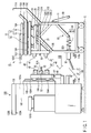
- a probe card transporting apparatus 10 has a truck 11 and transporting mechanism 12, as shown in, e.g., FIG. 1.
- the truck 11 can move on a floor surface G freely.
- the transporting mechanism 12 is arranged above the truck 11 to be able to separate from and come into contact with it.
- the transporting mechanism 12 transports a probe card C between the truck 11 and a prober 100.
- the prober 100 has a prober chamber 101, a head plate 102, and the probe card C.
- the prober chamber 101 tests the electrical characteristics of an object to be tested (e.g., a semiconductor wafer (to be referred to as a "wafer” hereinafter)) by using the probe card C.
- the head plate 102 forms the upper surface of the prober chamber 101.
- the probe card C is fixed to the head plate 102.
- the transporting mechanism 12 unloads the probe card C from and loads it in the prober chamber 101 through an opening 101A formed in the prober chamber 101.
- the head plate 102 has a probe card holder 102B, and the probe card C has a plurality of positioning holes 102C.
- the probe card holder 102B has a plurality of guide pins 102A.
- the guide pins 102A serve to reliably mount the probe card C transported by the transporting mechanism 12 on the probe card holder 102B.
- a stage 101B which can move in the horizontal and vertical directions is arranged in the prober chamber 101.
- a wafer is placed on the stage. While the electrodes of the wafer and probes C' (shown in FIG. 11) formed on the lower surface of the probe card C are in contact with each other, the electrical characteristics of the wafer are tested.
- a first connecting mechanism 130 connects the probe card transporting apparatus 10 to the prober 100.
- the first connecting mechanism 130 has at least one connection tool 31 (e.g., a square ring-like structure), a driving portion 32, and a second connecting mechanism 34.
- the driving portion 32 swings the connection tool 31 vertically.
- the second connecting mechanism 34 connects the driving portion 32 and a manipulation handle 33.
- the connection tool 31 incorporates a link mechanism and cylinder mechanism.
- the second connecting mechanism 34 has a coil spring 35 and link 36. The coil spring 35 is connected to a rod 32A of the cylinder mechanism of the driving portion 32.
- the link 36 is connected to the coil spring 35.
- the manipulation handle 33 is locked when it is pulled upward from the state shown in FIG. 1.
- the driving portion 32 has a coil spring which biases the connection tool 31 downward.
- the connection tool 31 is restored from the horizontal state to the tilted state by the spring force of the coil spring 35.
- the prober 100 has a connection pin 37 (constituting part of the first connecting mechanism 130) corresponding to the connection tool 31.
- a power receiving portion 11Ba is arranged on the front surface of the truck 11.
- a power supply portion 11Bb is arranged on the front surface of the prober 100.
- the power receiving portion 11Ba is electrically connected to the power supply portion 11Bb.
- the second connecting mechanism 34 and driving portion 32 move the connection tool 31 upward.
- the connection tool 31 that has moved upward fits in the connection pin 37 of the prober 100.
- the elastic coil spring 35 draws the connection tool 31, to connect the connection tool 31 and connection pin 37 reliably.
- projecting members are provided to the truck 11 and prober 100, respectively. The projecting members act against the drawing force of the connection tool 31.
- the transporting mechanism 12 can have an arm mechanism 14 which moves forward/backward on a base 13.
- the base 13 can be arranged above the truck 11 to be able to separate from and come into contact with it.
- the arm mechanism 14 can have first and second arms 15 and 16.
- the first arm 15 moves forward/backward on the base 13 in the back-and-forth direction.
- the second arm 16 moves forward/backward on the first arm 15 in the back-and-forth direction.
- the probe card C is placed on the second arm 16.
- the arm mechanism 14 can be moved forward/backward. As shown in FIG. 1, the first arm 15 moves forward/backward on the base 13.
- the second arm 16 moves forward/backward on the first arm 15.
- a mechanism that smoothes these forward/backward movement is preferably provided.
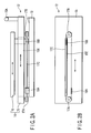
- a pair of left and right guide rails 15B and a pair of left and right guide rails 15C can be attached to the upper and lower surfaces, respectively, of the first arm 15.
- a low-friction plate, a bearing mechanism, an air bearing mechanism, a magnetic floating mechanism, or the like can be employed.
- the guide rails 15B and 15C engage with guide members 16A and 13A (see FIG. 1) attached to the lower surface of the second arm 16 and to the base 13, respectively.
- a plurality of mechanisms (e.g., guide pins) 15D for holding the probe card C are preferably arranged on the upper surface of the second arm 16. The guide pins 15D always hold the probe card C in a given direction.
- a pair of front and rear rotary bodies (e.g., pulleys) 17A and 17B are preferably rotatably attached to the lower surface of the first arm 15.
- the pair of rotary bodies 17A and 17B can be arranged inside the pair of guide rails 15C (FIG. 1).
- An endless belt 17C can be wound around the pulleys 17A and 17B.
- the endless belt 17C is connected to the base 13 and second arm 16 through first and second connection tools 18A and 18B, respectively.
- the first connection tool 18A can be fixed to the front end portion of the base 13, and the second connection tool 18B can be fixed to the rear end portion of the second arm 16.
- the second connection tool 18B extends through an elongated hole 15E of the first arm 15.
- the elongated hole 15E is formed in the first arm 15 in the back-and-forth direction.
- the second connection tool 18B connects the second arm 16 and endless belt 17C.
- the length of the elongated hole 15E of the first arm 15 can be set to correspond to the moving distance of the second arm 16.
- the endless belt 17C connected to the first connection tool 18A also moves for the same distance.
- the second arm 16 moves forward/backward on the first arm 15 in the same direction for the same distance. Consequently, the second arm 16 connected to the second connection tool 18B moves forward/backward on the base 13 at a speed twice that of the first arm 15 for a distance twice that of the first arm 15.
- the pair of front and rear pulleys 17A and 17B and the endless belt 17C may be arranged on the upper surface of the first arm 15.
- a lower plate 20 can be arranged on the lower surface of the base 13 through an elastic member 19 such as rubber.
- the lower plate 20 can have a first slide mechanism (e.g., a contact plate, bearing mechanism, air bearing mechanism, magnetic floating mechanism, or the like; to be referred to as a "first contact plate” hereinafter) 21A on its lower surface.
- the elastic member 19 can serve as a buffer member that absorbs impact generated when the transporting mechanism 12 lands on the truck 11, and impact received from the floor surface G when the truck 11 moves.
- the first contact plate 21A opposes a second slide mechanism (e.g., a contact plate, bearing mechanism, air bearing mechanism, magnetic floating mechanism, or the like; to be referred to as a "second contact plate” hereinafter) 21B attached to the upper surface of the truck 11.
- a second slide mechanism e.g., a contact plate, bearing mechanism, air bearing mechanism, magnetic floating mechanism, or the like; to be referred to as a "second contact plate” hereinafter
- Each of the contact plates 21A and 21B can be formed of a low-friction material (e.g., ethylene tetrafluoride resin) having a low coefficient of friction.
- the transporting mechanism 12 can separate from and come into contact with the truck 11 at the boundary of the first and second contact plates 21A and 21B.
- the transporting mechanism 12 is fixed at a predetermined position on the truck 11 by a position fixing mechanism 22 shown in FIG. 1.
- the position fixing mechanism 22 prevents the transporting mechanism 12 from falling from the truck 11 during transportation.
- the position fixing mechanism 22 can have first and second aligning/fixing mechanisms 22A and 22B, and a connecting mechanism 22C, as shown in FIG. 1.
- the first aligning/fixing mechanism 22A is arranged at substantially the center of the lower plate 20, and fits on the second aligning/fixing mechanism 22B.
- the connecting mechanism 22C connects the second aligning/fixing mechanism 22B and manipulation handle 33.
- the manipulation handle 33 is pulled upward counterclockwise from the position shown in FIG. 1.
- the second aligning/fixing mechanism 22B disengages from the first aligning/fixing mechanism 22A through the connecting mechanism 22C, so that the transporting mechanism 12 is released from the truck 11.
- the transporting mechanism 12 can slide on the truck 11 in the horizontal direction through the first and second contact plates 21A and 21B.
- the manipulation handle 33 is rotated clockwise from the pulled-up position, and is restored to the initial position.
- the aligning/fixing mechanism 22B fits in the aligning/fixing mechanism 22A, so that the transporting mechanism 12 is fixed on the truck 11.
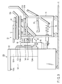
- FIG. 3 shows the practical structure of the position fixing mechanism 22.
- the position fixing mechanism 22 can have the first and second aligning/fixing mechanisms 22A and 22B, the connecting mechanism 22C, and a plurality of elastic members (e.g., four coil springs) 23.
- the plurality of coil springs are connected between the truck 11 and lower plate 20.
- the coil springs 23 always bias the base 13 of the transporting mechanism toward the reference position on the truck 11.
- the four coil springs 23 can be arranged radially in directions of substantially 90° from each other about the reference position as the center.
- the reference position is where the position of the first aligning/fixing mechanism 22A of the transporting mechanism 12 on the truck 11 substantially coincides with the position of the second aligning/fixing mechanism 22B of the truck 11.
- the first aligning/fixing mechanism 22A can have recesses 22Aa and through holes 22Ab.
- the recesses 22Aa are conically formed in the lower surface of the first aligning/fixing mechanism 22A.
- the through holes 22Ab extend from the conical recesses 22Aa toward the upper surface of the first aligning/fixing mechanism 22A.
- the first aligning/fixing mechanism 22A can be arranged to cover the front and rear portions of the lower plate 20.
- the second aligning/fixing mechanism 22B can have a pair of front and rear pins 22Ba and a support member 22Bb.
- the pins 22Ba extend through the front and rear through holes 22Ab of the first aligning/fixing mechanism 22A.
- the support member 22Bb supports the pins 22Ba.
- the connecting mechanism 22C can have a rod 22E, cylinder 22F, link 22G, pulley 22H, and timing belt 221.
- the rod 22E depends downward from the support member 22Bb of the second aligning/fixing mechanism 22B.
- the cylinder 22F guides the rod 22E in the vertical direction.
- the link 22G is connected to the rod 22E, projecting downward through the cylinder 22F, through a pin 22Ga.
- the pulley 22H is connected to the link 22G through a pin 22Gb.
- the timing belt 221 extends between the pulley 22H and the pulley (not shown) of the manipulation handle 33.
- An aligning mechanism 40 (41, 42) can be provided to the probe card transporting apparatus 10 and prober 100. After a connecting mechanism 130 connects the probe card transporting apparatus 10 and prober 100, the aligning mechanism 40 aligns them. More specifically, the aligning mechanism 40 has a support plate 13B depending downward from the front end portion of the lower surface of the base 13, as shown in FIG. 1. The support plate 13B has a plurality of (e.g., three; only two are shown in FIG. 1) engaging projections 41. Three engaging recesses 42 can be arranged below the opening 101A of the prober chamber 101. The engaging recesses 42 engage with the corresponding engaging projections 41. A support body 103 can be attached to the front surface of the prober chamber 101.
- a pair of left and right guide rails 103A can be attached to the support body 103.
- An elevating body 104 is attached to the guide rails 103A through engaging members 104A.
- the elevating body 104 moves upward/downward along the guide rails 103A.
- the plurality of (e.g., three) engaging recesses 42 are arranged on the elevating body 104.
- the engaging recesses 42 can have a shape such as an inverted triangle, an inverted cone, or the like.
- the engaging portions of the engaging projections 41 can be formed as, e.g., conical projections.
- the engaging portions of the engaging recesses 42 can be formed as conical recesses. Assume that the engaging projections 41 and engaging recesses 42 have conical shapes. Even if the floor surface G is somewhat tilted, the probe card transporting apparatus 10 and prober 100 can be reliably engaged with each other by only roughly aligning the probe card transporting apparatus 10 with the prober 100.
- a fixing mechanism 50 can be further provided to the prober 100, as shown in FIG. 1. After alignment with the prober 100 is performed, the fixing mechanism 50 fixes the probe card transporting apparatus 10 and prober 100 while aligning them reliably.
- the fixing mechanism 50 can have a pair of left and right driving mechanisms (e.g., air cylinders) 51, plate-like engaging elements 52, and L-shaped to-be-engaged elements 53, as shown in FIG. 1.
- the air cylinders 51 are arranged on the elevating body 104 between the upper and lower engaging recesses 42.
- the engaging elements 52 are horizontally attached to the distal ends of piston rods 51A of the air cylinders 51.
- the to-be-engaged elements 53 are attached to the support plate 13B such that the engaging elements 52 engage with them.
- the cylinder rods 51A can be rotated forward and backward by rotating mechanisms 51B.
- the probe card transporting apparatus 10 While the piston rods 51A of the fixing mechanism 50 are extended, the probe card transporting apparatus 10 approaches the prober 100.
- the to-be-engaged elements 53 reach deep into the engaging elements 52, the engaging elements 52 rotate through a rotary driving mechanism.
- the engaging elements 52 and to-be-engaged elements 53 engage with each other.
- the air cylinders 51 retract the piston rods 51A, the transporting mechanism 12 is pulled toward the prober 100 through the engaging elements 52 and to-be-engaged elements 53, and is fixed to the prober 100.
- An elevating body driving mechanism e.g., an air cylinder
- the air cylinder 60 is attached to the lower portion of the prober chamber 101 with its piston rod 61 facing up.
- the elevating body 104 can be moved vertically through the piston rod 61.
- reference numeral 11A denotes a handle attached to the rear end of the truck 11.
- the operator holds the handle 11A and moves the probe card transporting apparatus 10 by pushing it.
- Switches (not shown) for driving the elevating air cylinder 60 can be attached to the handle 11A.
- the air cylinder 60 can be driven by operating these switches.
- a stopper mechanism 70 which regulates forward movement of the arm mechanism 14 can be arranged on the base 13 of the transporting mechanism 12.
- the stopper mechanism 70 has an abutting member 71, first rod 72, and first and second cylinders 73 and 76.
- the abutting member 71 abuts against the prober 100.
- the first rod 72 has the abutting member 71 at its distal end.
- the first cylinder 73 guides the rod 72 in the horizontal direction.
- the second cylinder 76 vertically guides a rod 75 arranged vertically.
- the second rod 75 is pin-connected to the proximal end portion of the first rod 72, extending through the cylinder 73, through a link 74.
- a flange 72A is formed on the distal end of the first rod 72.
- a spring coil 77 is elastically interposed between the flange 72A and first cylinder 73.
- the distal end portion of the second rod 75 projecting from the upper end of the second cylinder 76 engages with a locking member 78 attached to the first arm 15.
- the distal end of the second rod 75 regulates the first arm 15 from popping up from the base 13.
- the arm mechanism 14 can move forward.
- the truck 11 is movable.
- the transporting mechanism 12 is arranged above the truck 11 to be able to separate from and come into contact with it.
- the transporting mechanism 12 transports the probe card C between the truck 11 and prober 100.
- the transporting mechanism 12 has the base 13 and arm mechanism 14.
- the arm mechanism 14 moves forward/backward on the base 13.
- the aligning mechanism 40 for alignment with the prober 100 and fixing mechanism 50 for fixing to the prober 100 are provided to the base 13. After the transporting mechanism 12 is aligned with the prober 100 through the aligning mechanism 40, it can be reliably fixed to the prober 100 through the fixing mechanism 50.
- the transporting mechanism 12 can separate from the truck 11 and maintain the parallel state of the probe card C in the prober 100, and can smoothly attach and detach the probe card C to and from the card clamp mechanism of the head plate 102.
- connection manipulating mechanism 30 connects the truck 11 to the prober 100. After the probe card transporting apparatus 10 is moved close to the prober 100, the connection manipulating manipulation mechanism 30 is manipulated. Thus, the probe card transporting apparatus 10 can be reliably connected to the prober 100. The probe card transporting apparatus 10 and prober 100 can be aligned and fixed more reliably.
- the position fixing mechanism 22 fixes the truck 11 and transporting mechanism 12 to each other.
- the transporting mechanism 12 will not be positionally displaced on the truck 11 or fall from the truck 11.
- the coil springs 23 elastically connect the truck 11 and transporting mechanism 12.
- the first and second contact plates 21A and 21B having a small coefficients of friction are provided to the contact surfaces of the truck 11 and transporting mechanism 12.
- the transporting mechanism 12 has the base 13 and the first and second arms 15 and 16.
- the first arm 15 moves forward/backward on the base 13.
- the second arm 16 moves forward/backward on the first arm 15.
- the pair of pulleys 17A and 17B are arranged at the front and rear portions of the first arm 15.
- the endless belt 17C extends between the pulleys 17A and 17B.
- the first and second connection tools 18A and 18B connect the base 13 and second arm 16, respectively, to the endless belt 17C.
- the second arm 16 can be moved at a speed twice that of the first arm 15 for a distance twice that of the first arm 15 by only moving the first arm 15.
- the transportation time of the probe card C can be shortened, and the operation of moving the transporting mechanism 12 forward/backward is facilitated.
- the prober 100 of this embodiment has the elevating body 104, aligning mechanism 40, fixing mechanism 50, and elevating air cylinder 60.
- the elevating body 104 is arranged on the opening 101A-side surface of the prober chamber 101 to be movable vertically.
- the aligning mechanism 40 is provided to the elevating body 104 and aligns the transporting mechanism 12 with the prober chamber 101.
- the fixing mechanism 50 is provided to the elevating body 104 and fixes the base 13 of the transporting mechanism 12 to the prober chamber 101.
- the air cylinder 60 moves the elevating body 104 vertically.
- the prober 100 can be expected to have the same operation and effect as those of the probe card transporting apparatus 10.
- the head plate 102 has a position fixing mechanism which fixes the probe card C, loaded by the transporting mechanism 12, in the horizontal direction. The probe card C transported by the transporting mechanism 12 can be reliably attached to and detached from the head plate 102 without failure.
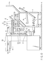
- FIGS. 12 to 14 are conceptual views showing a probe card transporting apparatus according to another embodiment of the present invention.
- a probe card transporting apparatus 110 according to this embodiment has a truck 111 and transporting mechanism 112, as shown in FIG. 12.
- the truck 111 can move on the floor surface G freely.
- the transporting mechanism 112 is arranged above the truck 111 to be able to separate from and come into contact with it.
- the transporting mechanism 112 transports a probe card C between the truck 111 and a prober 200.
- the truck 111 and transporting mechanism 112 can be formed in the same manner as in the embodiment described with reference to FIGS. 1 to 11.
- the transporting mechanism 112 has a base 113 and first and second arms 115 and 116.
- the second arm 116 can move at a speed twice that of the first arm 115 for a distance twice that of the first arm 115, in the same manner as the transporting mechanism 12 shown in FIG. 2.
- the first and second arms 115 and 116 move forward on the base 113.
- a tilt prevention mechanism 120 supports the first and second arms 115 and 116 from below, when they are tilted by the weight of a probe card C which is particularly heavy, thus preventing them from tilting forward.
- a connecting mechanism 30, aligning mechanism 40, fixing mechanism 50, elevating body driving mechanism 60, and the like which are identical to those of the embodiment described with reference to FIGS. 1 to 11 are omitted.
- the tilt prevention mechanism 120 has a manipulation handle 121, substantially V-shaped lever member 122, and abutting member 123.
- the lever member 122 is axially supported by the base 113.
- the abutting member 123 is attached to the distal end of the lever member 122.
- the manipulation handle 121 is manipulated, the lever member 122 swings to lift the abutting member 123 upward.
- the abutting member 123 supports the first arm 115 from below.
- the tilt prevention mechanism 120 prevents a tilt of the transporting mechanism 112 which has moved forward from the truck 111. Assume that the second arm 116 of the transporting mechanism 112 enters the prober 200 and that the transporting mechanism 112 is tilted by the weight of the probe card C which is particularly heavy. Even in this case, the tilt prevention mechanism 120 lifts the probe card C upward and corrects it horizontally. The probe card C can be transferred smoothly, and the transporting mechanism 112 need not have high rigidity. Rather, the transporting mechanism 112 can be made lightweight.
- the present invention is not limited to the above embodiments at all, and the design of the respective constituent elements can be changed when necessary.
- the connecting mechanism 22C of the position fixing mechanism 22 the connecting mechanism 34 of the connection manipulating mechanism 30, and the like
- various types of mechanisms can be used.
- the engaging elements 52 and to-be-engaged elements 53 of the fixing mechanism 50 can take other shapes.
- a driving mechanism other than an air cylinder can be employed.
- the footprint of the prober can be decreased.
- a large probe card can be maintained in the parallel state in the prober without being adversely affected by a tilt of the floor surface or the like.
- the probe card can be smoothly transported to the head plate, and can be attached to and detached from it.
Landscapes
- Engineering & Computer Science (AREA)
- Mechanical Engineering (AREA)
- Computer Hardware Design (AREA)
- Microelectronics & Electronic Packaging (AREA)
- General Engineering & Computer Science (AREA)
- Physics & Mathematics (AREA)
- General Physics & Mathematics (AREA)
- Testing Or Measuring Of Semiconductors Or The Like (AREA)
- Testing Of Individual Semiconductor Devices (AREA)
- Measuring Leads Or Probes (AREA)
- Tests Of Electronic Circuits (AREA)
Applications Claiming Priority (2)
| Application Number | Priority Date | Filing Date | Title |
|---|---|---|---|
| JP2002379041 | 2002-12-27 | ||
| JP2002379041A JP4391744B2 (ja) | 2002-12-27 | 2002-12-27 | 移動式プローブカード搬送装置、プローブ装置及びプローブ装置へのプローブカードの搬送方法 |
Publications (2)
| Publication Number | Publication Date |
|---|---|
| EP1435645A2 true EP1435645A2 (de) | 2004-07-07 |
| EP1435645A3 EP1435645A3 (de) | 2004-09-01 |
Family
ID=32501140
Family Applications (1)
| Application Number | Title | Priority Date | Filing Date |
|---|---|---|---|
| EP03029655A Withdrawn EP1435645A3 (de) | 2002-12-27 | 2003-12-23 | Ein Transportmechanismus, bewegliche Transportvorrichtung für Testkarten, die eine Transportmechanismus benutzen und eine Testvorrichtung |
Country Status (7)
| Country | Link |
|---|---|
| US (2) | US6958618B2 (de) |
| EP (1) | EP1435645A3 (de) |
| JP (1) | JP4391744B2 (de) |
| KR (1) | KR100671069B1 (de) |
| CN (1) | CN1321327C (de) |
| SG (1) | SG115601A1 (de) |
| TW (1) | TW200503049A (de) |
Families Citing this family (23)
| Publication number | Priority date | Publication date | Assignee | Title |
|---|---|---|---|---|
| JP4875332B2 (ja) * | 2005-09-21 | 2012-02-15 | 東京エレクトロン株式会社 | プローブカード移載補助装置及び検査設備 |
| JP2007147536A (ja) | 2005-11-30 | 2007-06-14 | Tokyo Electron Ltd | プローブカード移載補助装置及び検査設備 |
| JP2007165715A (ja) * | 2005-12-15 | 2007-06-28 | Tokyo Electron Ltd | プローブカードの装着方法及びこの方法に用いられるプローブカード移載補助装置 |
| US7232179B1 (en) * | 2005-12-16 | 2007-06-19 | Volvo Trucks North America | Modular day/sleeper cab and interface therefor |
| KR100833285B1 (ko) * | 2006-12-27 | 2008-05-28 | 세크론 주식회사 | 프로브카드 운반장치 |
| JP4965273B2 (ja) * | 2007-02-02 | 2012-07-04 | 東京エレクトロン株式会社 | 載置装置 |
| JP5049419B2 (ja) * | 2007-07-25 | 2012-10-17 | 東京エレクトロン株式会社 | プローブカード用台車及びこの台車を用いるプローブカードの取り扱い方法 |
| JP5377915B2 (ja) * | 2008-09-30 | 2013-12-25 | 東京エレクトロン株式会社 | 検査装置及び検査方法 |
| JP5384219B2 (ja) * | 2009-06-19 | 2014-01-08 | 東京エレクトロン株式会社 | 検査装置におけるプリアライメント方法及びプリアライメント用プログラム |
| WO2011013231A1 (ja) * | 2009-07-30 | 2011-02-03 | 株式会社アドバンテスト | プローブカード保持装置及びプローバ |
| US8872532B2 (en) * | 2009-12-31 | 2014-10-28 | Formfactor, Inc. | Wafer test cassette system |
| JP5517350B2 (ja) * | 2010-06-15 | 2014-06-11 | 東京エレクトロン株式会社 | 載置台駆動装置 |
| JP6031292B2 (ja) * | 2012-07-31 | 2016-11-24 | 東京エレクトロン株式会社 | プローブカードへの基板当接方法 |
| JP6349853B2 (ja) | 2013-06-27 | 2018-07-04 | 株式会社デンソーウェーブ | 産業用ロボット |
| KR102335827B1 (ko) | 2014-12-24 | 2021-12-08 | 삼성전자주식회사 | 프로브 카드 로딩 장치, 그를 포함하는 프로브 카드 관리 시스템 |
| FR3066186A1 (fr) * | 2017-05-09 | 2018-11-16 | Getinge La Calhene | Chariot de manipulation d'un conteneur en vue de sa connexion a un isolateur |
| US10261109B2 (en) | 2017-05-17 | 2019-04-16 | Globalfoundries Inc. | Probe card support insert, container, system and method for storing and transporting one or more probe cards |
| CN108655804A (zh) * | 2018-06-13 | 2018-10-16 | 上海交大智邦科技有限公司 | 一种全自动快速切换工装夹具系统 |
| WO2020003581A1 (ja) * | 2018-06-29 | 2020-01-02 | パナソニックIpマネジメント株式会社 | 作業システム及びフィーダ台車の搬送方法 |
| CN109436070B (zh) * | 2018-12-12 | 2020-12-08 | 博兴兴业精细化工产业发展有限公司 | Pvc管材定量搬运机械 |
| DE102019111401A1 (de) * | 2019-05-02 | 2020-11-05 | Deckel Maho Pfronten Gmbh | System mit einer transporteinrichtung zum transportieren eines transportgutträgers, einem transportgutträger und einer aufnahmevorrichtung |
| DE102019214081A1 (de) * | 2019-09-16 | 2021-03-18 | Deckel Maho Pfronten Gmbh | Ent- bzw. beladevorrichtung und ent- bzw. beladesystem zum einsatz an einer oder mehreren werkzeugmaschinen |
| CN119595953B (zh) * | 2024-12-30 | 2025-08-26 | 南京木木西里科技有限公司 | 一种探针自动更换平台 |
Family Cites Families (28)
| Publication number | Priority date | Publication date | Assignee | Title |
|---|---|---|---|---|
| US1079927A (en) * | 1912-05-20 | 1913-11-25 | Gen Patents Company Inc | Extension-table. |
| FR1191667A (fr) * | 1958-02-18 | 1959-10-21 | Lip | Procédé de commande à distance d'un élément mobile à partir d'un support fixe,dispositif pour sa mise en oeuvre, et ses diverses applications |
| US3078129A (en) * | 1960-06-22 | 1963-02-19 | Otto A Beeck | Band controlled extension slide |
| US3521939A (en) * | 1968-02-23 | 1970-07-28 | Herbert S Fall | Stop system |
| US3745725A (en) * | 1971-01-11 | 1973-07-17 | A Boucaud | Extensible structure |
| JPS5029841A (de) * | 1973-07-17 | 1975-03-25 | ||
| JPH07115773B2 (ja) * | 1986-01-29 | 1995-12-13 | 株式会社ニコン | 基板搬送装置 |
| US4836733A (en) * | 1986-04-28 | 1989-06-06 | Varian Associates, Inc. | Wafer transfer system |
| KR970004947B1 (ko) * | 1987-09-10 | 1997-04-10 | 도오교오 에레구토론 가부시끼가이샤 | 핸들링장치 |
| CH675762A5 (de) * | 1988-10-03 | 1990-10-31 | Peter Huerlimann | |
| SE463219B (sv) * | 1989-10-16 | 1990-10-22 | Sky Park Ab | Linjaer vaexel saerskilt vid transfervagn i parkeringshus |
| JPH03220742A (ja) * | 1990-01-25 | 1991-09-27 | Tokyo Seimitsu Co Ltd | プロービングマシン |
| JP2606554Y2 (ja) * | 1992-01-17 | 2000-11-27 | 株式会社東京精密 | プロービング装置 |
| US5254939A (en) * | 1992-03-20 | 1993-10-19 | Xandex, Inc. | Probe card system |
| JPH06236909A (ja) | 1993-02-08 | 1994-08-23 | Tokyo Electron Yamanashi Kk | プローブ装置 |
| JP2605995Y2 (ja) * | 1993-05-17 | 2000-09-04 | 日本トムソン株式会社 | スライド装置 |
| US5528158A (en) * | 1994-04-11 | 1996-06-18 | Xandex, Inc. | Probe card changer system and method |
| US5640100A (en) * | 1994-10-22 | 1997-06-17 | Tokyo Electron Limited | Probe apparatus having probe card exchanging mechanism |
| JP3220742B2 (ja) * | 1996-02-01 | 2001-10-22 | 東光資材株式会社 | 玉掛け用具の端部処理構造 |
| US6126381A (en) * | 1997-04-01 | 2000-10-03 | Kensington Laboratories, Inc. | Unitary specimen prealigner and continuously rotatable four link robot arm mechanism |
| US6450755B1 (en) * | 1998-07-10 | 2002-09-17 | Equipe Technologies | Dual arm substrate handling robot with a batch loader |
| US6249342B1 (en) * | 1999-07-06 | 2001-06-19 | David Cheng | Method and apparatus for handling and testing wafers |
| JP4104099B2 (ja) * | 1999-07-09 | 2008-06-18 | 東京エレクトロン株式会社 | プローブカード搬送機構 |
| US6705816B2 (en) * | 2000-06-09 | 2004-03-16 | Waypoint Technologies | Wafer transport mechanism |
| JP4558981B2 (ja) * | 2000-11-14 | 2010-10-06 | 株式会社ダイヘン | トランスファロボット |
| JP4798595B2 (ja) | 2001-08-07 | 2011-10-19 | 東京エレクトロン株式会社 | プローブカード搬送装置及びプローブカード搬送方法 |
| JP4134289B2 (ja) * | 2002-05-29 | 2008-08-20 | 東京エレクトロン株式会社 | プローブカード搬送装置及びアダプタ |
| JP4061146B2 (ja) * | 2002-07-22 | 2008-03-12 | シャープ株式会社 | レンズのマウント装置及び投射型表示装置 |
-
2002
- 2002-12-27 JP JP2002379041A patent/JP4391744B2/ja not_active Expired - Lifetime
-
2003
- 2003-12-22 SG SG200307840A patent/SG115601A1/en unknown
- 2003-12-23 US US10/742,905 patent/US6958618B2/en not_active Expired - Lifetime
- 2003-12-23 EP EP03029655A patent/EP1435645A3/de not_active Withdrawn
- 2003-12-24 TW TW092136757A patent/TW200503049A/zh not_active IP Right Cessation
- 2003-12-26 KR KR1020030097387A patent/KR100671069B1/ko not_active Expired - Lifetime
- 2003-12-29 CN CNB2003101103914A patent/CN1321327C/zh not_active Expired - Lifetime
-
2005
- 2005-08-25 US US11/210,859 patent/US7385386B2/en not_active Expired - Lifetime
Also Published As
| Publication number | Publication date |
|---|---|
| US6958618B2 (en) | 2005-10-25 |
| EP1435645A3 (de) | 2004-09-01 |
| CN1519572A (zh) | 2004-08-11 |
| CN1321327C (zh) | 2007-06-13 |
| TW200503049A (en) | 2005-01-16 |
| US20040183525A1 (en) | 2004-09-23 |
| US7385386B2 (en) | 2008-06-10 |
| TWI303841B (de) | 2008-12-01 |
| US20050280431A1 (en) | 2005-12-22 |
| KR20040060799A (ko) | 2004-07-06 |
| JP4391744B2 (ja) | 2009-12-24 |
| KR100671069B1 (ko) | 2007-01-17 |
| SG115601A1 (en) | 2005-10-28 |
| JP2004212081A (ja) | 2004-07-29 |
Similar Documents
| Publication | Publication Date | Title |
|---|---|---|
| EP1435645A2 (de) | Ein Transportmechanismus, bewegliche Transportvorrichtung für Testkarten, die eine Transportmechanismus benutzen und eine Testvorrichtung | |
| US20210331327A1 (en) | Robot gripper for moving wafer carriers and packing materials and method of operating the same | |
| KR101233101B1 (ko) | 저용량 캐리어 및 그 사용방법 | |
| EP1331659B1 (de) | Zentrierungsmechanismus, Zentrierungseinheit, Apparat zur Herstellung von Halbleitern und Zentrierungsmethode | |
| JP7145029B2 (ja) | 半導体資材の切断装置 | |
| JPH10232262A (ja) | 半導体デバイスのテスト用搬送装置 | |
| US20260084320A1 (en) | Robot gripper for moving wafer carriers and packing materials and method of operating the same | |
| KR102829516B1 (ko) | 비히클 | |
| CN103226177A (zh) | 用于电子器件的测试装置 | |
| US20020011854A1 (en) | Probe device | |
| KR19990088192A (ko) | 트레이이송암,전자부품시험장치및트레이반송방법 | |
| US6209194B1 (en) | Apparatus for loading and unloading semiconductor device packages using servo motors | |
| CN111446183A (zh) | 卡盘顶、检查装置以及卡盘顶的回收方法 | |
| KR100899927B1 (ko) | 캐리어모듈 개방장치, 그를 포함하는 테스트 핸들러, 및그를 이용한 반도체 소자 제조방법 | |
| KR100917001B1 (ko) | 테스트 핸들러용 트레이 공급회수장치 및 이를 이용한트레이 이송방법 | |
| US6695546B2 (en) | Single drive aligner elevation apparatus for an integrated circuit handler | |
| US5865670A (en) | Wafer demount apparatus | |
| KR100976739B1 (ko) | 반도체 디바이스를 테스트 하기 위한 컨텍터 장치 및 그 작동 방법 | |
| CN119490033A (zh) | 测试处理机 | |
| KR20200057161A (ko) | 웨이퍼 보관이 가능한 웨이퍼 프로버용 로더 | |
| CN117690858A (zh) | 机械手组件及探针台 | |
| KR102793895B1 (ko) | 보드 조립체 및 이를 포함하는 테스트 핸들러 | |
| KR101361497B1 (ko) | 테스트핸들러용 캐리어보드 이송장치 및 자세변환장치 | |
| KR100776814B1 (ko) | 전자부품 테스트용 핸들러 | |
| KR0140289B1 (ko) | 카세트의 이송장치 |
Legal Events
| Date | Code | Title | Description |
|---|---|---|---|
| PUAI | Public reference made under article 153(3) epc to a published international application that has entered the european phase |
Free format text: ORIGINAL CODE: 0009012 |
|
| AK | Designated contracting states |
Kind code of ref document: A2 Designated state(s): AT BE BG CH CY CZ DE DK EE ES FI FR GB GR HU IE IT LI LU MC NL PT RO SE SI SK TR |
|
| AX | Request for extension of the european patent |
Extension state: AL LT LV MK |
|
| PUAL | Search report despatched |
Free format text: ORIGINAL CODE: 0009013 |
|
| AK | Designated contracting states |
Kind code of ref document: A3 Designated state(s): AT BE BG CH CY CZ DE DK EE ES FI FR GB GR HU IE IT LI LU MC NL PT RO SE SI SK TR |
|
| AX | Request for extension of the european patent |
Extension state: AL LT LV MK |
|
| 17P | Request for examination filed |
Effective date: 20050301 |
|
| AKX | Designation fees paid |
Designated state(s): AT BE BG CH CY CZ DE DK EE ES FI FR GB GR HU IE IT LI LU MC NL PT RO SE SI SK TR |
|
| 17Q | First examination report despatched |
Effective date: 20100326 |
|
| STAA | Information on the status of an ep patent application or granted ep patent |
Free format text: STATUS: THE APPLICATION IS DEEMED TO BE WITHDRAWN |
|
| 18D | Application deemed to be withdrawn |
Effective date: 20100806 |