EP1428918A2 - Tuyère auxiliaire pour un métier à tisser - Google Patents
Tuyère auxiliaire pour un métier à tisser Download PDFInfo
- Publication number
- EP1428918A2 EP1428918A2 EP04004657A EP04004657A EP1428918A2 EP 1428918 A2 EP1428918 A2 EP 1428918A2 EP 04004657 A EP04004657 A EP 04004657A EP 04004657 A EP04004657 A EP 04004657A EP 1428918 A2 EP1428918 A2 EP 1428918A2
- Authority
- EP
- European Patent Office
- Prior art keywords
- auxiliary nozzle
- hollow needle
- outflow opening
- upper edge
- auxiliary
- Prior art date
- Legal status (The legal status is an assumption and is not a legal conclusion. Google has not performed a legal analysis and makes no representation as to the accuracy of the status listed.)
- Granted
Links
Images


Classifications
-
- D—TEXTILES; PAPER
- D03—WEAVING
- D03D—WOVEN FABRICS; METHODS OF WEAVING; LOOMS
- D03D47/00—Looms in which bulk supply of weft does not pass through shed, e.g. shuttleless looms, gripper shuttle looms, dummy shuttle looms
- D03D47/28—Looms in which bulk supply of weft does not pass through shed, e.g. shuttleless looms, gripper shuttle looms, dummy shuttle looms wherein the weft itself is projected into the shed
- D03D47/30—Looms in which bulk supply of weft does not pass through shed, e.g. shuttleless looms, gripper shuttle looms, dummy shuttle looms wherein the weft itself is projected into the shed by gas jet
- D03D47/3006—Construction of the nozzles
- D03D47/302—Auxiliary nozzles
Definitions
- the invention relates to an auxiliary nozzle for a weaving machine, which is designed as a hollow needle and which in one to a closed Point adjoining wall with one or more Outflow openings is provided when the auxiliary nozzle attached to the loom on a weft insertion channel are directed.
- auxiliary nozzles are known from US Pat. No. 5,020,574. She support the insertion of a weft thread into the shed a loom. There are several such auxiliary nozzles for this purpose arranged across the width of the sley, each deliver a fluid flow that is transporting one into one Weft insertion channel of a reed blown-in weft supported. The auxiliary nozzles are arranged so that the one attached in a wall below the top Blow opening or blow opening in a certain position to the top wall and the back wall of the weft insertion channel are aligned. The one flowing out of the blow orifice Fluid flow is essentially in the longitudinal direction of the Shot entry channel directed and has a component diagonally upwards.
- the auxiliary nozzles move with every weft insertion through the lower warp thread level into the shed. It is established that warp threads that consist of several thin single filaments and are only slightly twisted, fray or fray at the spots, where the auxiliary nozzles through the lower warp thread level into the The shed is moved in and out again. This unraveling or Fraying occurs mainly in filament threads, which are thin Plastic filaments run essentially parallel to one another and at regular intervals Distances are welded together. In this case, a Fabric woven in the places where the auxiliary nozzles go through the lower one Warp thread plane has a different appearance than the rest of the tissue. In the area of the auxiliary nozzles, these warp threads get a Larger volume than the other Velcro threads because the thin filaments are not are arranged exactly next to each other.
- the invention has for its object an auxiliary nozzle of the aforementioned Type in such a way that the risk of damage to warp threads is reduced.
- the outflow opening is close to the upper edge the hollow needle is arranged so that - when the auxiliary nozzle in a Loom is installed - the outflow opening completely through the early Warp thread level passes through and out late through the warp thread level the shed moved out. It is through the auxiliary nozzle according to the invention possible that the fluid flow from the or the outlet openings less or less adversely affects the warp threads.
- the hollow needle in the Area of the tip is provided with a bulge that leads to the weaving smooth is directed when the auxiliary nozzle is installed in the loom.
- the walls of the bulge connect continuously to the walls of the hollow needle.
- the bulge has a wall which is substantially the same as the outflow opening wall or openings aligned.
- the cross section of the interior perpendicular this can then be reduced. So that's the advantageous one Further training possible that at least those with the or the wall provided with the outflow openings has an increased wall thickness having.
- the wall thickness can be increased without the flow cross-section to the outflow openings is reduced and the flow resistance is increased as the widening of the interior in the area of the bulge the flow cross section increased.
- outflow opening or outflow openings as nozzles are designed. With this nozzle shape, the or bundle and straighten the fluid jets better so that they are one develop greater driving force on a weft thread can.
- the tip of the hollow needle has a substantially straight upper edge has that extends up to the bulge extends. It is advantageously provided that the Top edge at an angle between 70 ° and 110 ° to the longitudinal axis the hollow needle runs.
- the loom shown in Fig. 1 has a reed 3, which consists of a variety of slats, each have a cutout around a U-shaped weft insertion channel 4 to form.
- weft insertion channel 4 weft threads 1, 2 are entered in a shed 21, the from warp threads in an upper and a lower warp thread level 17, 18 is formed, as shown in Figs. 2 and 3 is.
- the weft threads 1 or 2 are each from a main blowing nozzle 5, 6 blown.
- the further transport of the weft threads 1 or 2 is supported by air jets 7 which Blow auxiliary nozzles 8 into the weft insertion channel 4.
- the Air jets 7 are substantially in the longitudinal direction of the Weft insertion channel 4 directed and have a slight obliquely upward component that to the top Wall 15 and the rear wall of the weft insertion channel 4 the weft threads 1, 2 is directed.
- the reed 3, the Main blowing nozzles 5, 6 and the holder 9 of the auxiliary nozzles 8 are on attached to a shop profile 10 of a sley, such as that is known from US 50 20 574.
- the store profile For example, 10 is not on one of the stilts illustrated shaft of the sley attached to the back and forth movement is driven.
- a shed 21 becomes one upper warp thread level 17 and a lower warp thread level 18 formed, which converge in the stop line 19 on the weft threads are struck by the reed 3, so that a fabric 20 is formed. Striking one Weft takes place through the rear wall 16 of the U-shaped Weft insertion channel 4 leading to the central part 24 of the reed heard.
- the upper part 23 of the slats of the reed 3 forms an upper wall 15 of the guide channel 4.
- the lower Wall 14 of the guide channel 4 is from the lower part 22 of the Slats of the reed 3 are formed.
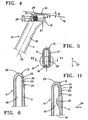
- the auxiliary nozzle 8 is as Hollow needle 11 designed near its tip 12 in one Side wall 26 is provided with an outflow opening 25. how 4 can be seen, the blowing opening 25 consists of a Many small openings.
- the hollow needle 11 of the auxiliary nozzle 8 is in the area of the tip 12 with a lateral bulge 13 provided, which faces the reed 3, if the auxiliary nozzle 8 is attached to the sley.
- the bulge 13 has a side wall 27, which is essentially lies in the extension of the side wall 26 of the hollow needle 11, in which the outflow opening 25 is provided.
- the bulge 13 is near the lower part 22 of the reed 3 in Area of the lower wall 14 of the weft insertion channel 4 arranged.
- the distance D between the bulge 13 and the lower part 22 of the reed is, for example, smaller than 3mm.
- the auxiliary nozzle 8 is provided with an upper edge 28 which is extends into the region of the bulge 13.
- the essentially rectilinear upper edge 28 closes with curves with relative large radius to the hollow needle 11 and the bulge 13 on.
- the highest point 30 of the tip 12 of the hollow needle 11 is located in the region of the bulge 13.
- the upper edge 28 of the auxiliary nozzle extends 8, when mounted on the sley, approximately tangential to a circle 31 around the axis of the shaft of the sley.
- the Upper edge 28 at an angle of approximately 110 ° to the longitudinal axis 32 the auxiliary nozzle 8.
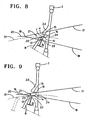
- the auxiliary nozzles 8 are by means of the movement of the sley for every weft thread entry between the warp threads of the warp thread level 18 into the shed 21 and after striking of the weft thread through the warp thread plane 18 again moved out of the shed 21.
- the angle H is like this designed that the near the reed 3 highest point 30 of the upper edge 28 of the bulge 13 first comes into contact with this lower warp thread level 18.
- the warp thread levels 17 and 18 move further apart into the position according to FIG. 2, when the auxiliary nozzles 8 into the lower warp thread plane 18th penetration.
- the warp threads 18 lie on the side walls 27, 33 the bulge 13 and on the slats 38 of the reed 3 on. This has the consequence that the near the blow opening 25 of the Auxiliary nozzles 8 located warp threads 18 are tensioned.
- This Tensioning causes warp threads that consist of several juxtaposed thin filaments exist that the filaments something to be pressed against each other. This causes that the air jet 7 of the auxiliary nozzles 8 between the less individual filaments can penetrate. This too is the unraveling of warp threads limited.
- the 8 to 11 is the same Auxiliary nozzle 8 with a side facing the reed 3 Bulge 13 provided.
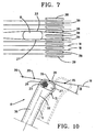
- this lower warp thread plane 18 has an angle H which is so designed is that the part of the upper edge facing the reed 3 28 last and the part facing away from the reed 3 the upper edge 28 first with the warp threads of the lower warp thread plane 18 comes into contact. While the auxiliary nozzle 8 through the warp thread plane 18 is moved through, the upper edge offers 28, as shown in Fig.
- a guide for Spot welds 35 with which the individual is substantially parallel mutually extending filament threads of a warp thread the lower warp thread level 18 are interconnected.
- Spot weld 35 can be above the upper edge 28 of the auxiliary nozzle 8 slide as it enters the shed and settles in the position shown in dashed lines in Fig. 10 moves. by virtue of the relatively large length of the top edge 28 and the angle H is avoided that the auxiliary nozzle 8 between the individual Filament threads of a warp thread of the lower warp thread level 18 can guess.
- the upper edge 28 is so long that the Auxiliary nozzle 8, which is moved with the sley, not between two successive welding spots 35 in one Warp thread of the lower warp thread level 18 can penetrate. In order to prevents the auxiliary nozzles 8 due to their movement tear open the welding spots 35.
- the angle of the upper edge 28 to the longitudinal axis 32 and / or the Shape of the auxiliary nozzle 8 designed as a hollow needle 11 expediently on the material of the processed warp threads so coordinated that when entering the shed the Warp threads are not damaged, i.e. not frayed or be frayed.
- This angle is preferably of the order of magnitude from 70 ° to 110 °.
- the cross section of the cavity 36 of the hollow needle 11 of the auxiliary nozzle 8 is in the area of the beginning of the bulge 13 (arrow direction 34 of FIG. 11) less than in the previous one Section 39.
- the wall thickness of the auxiliary nozzle 8 is in the range the outflow opening 25 larger than in the rest of the area Tip 12. Due to the larger wall thickness, it is possible the emerging fluid jet in the individual openings of the outflow opening better to guide because of the length of the openings is bigger. This can also limit the risk that an air jet 7 (Fig. 1) damages the warp threads.
- the cavity 36 within the To make the auxiliary nozzle 8 aerodynamically efficient, i.e. favorable for an air jet 7 from the outflow opening 25.
- the inner thickening 29 shown in FIG can be provided that deflect the fluid flow the outflow opening 25 improved.
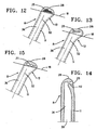
- the individual openings are the outflow opening 25 closer to the upper edge 28 of the auxiliary nozzle 8 arranged and not on an approximately circular surface, but divided into three rows one above the other.
- the Individual openings also extend into the area of Bulge 13 so that the same number of individual openings (19 individual openings in the exemplary embodiment) closer to the upper edge 28 can be accommodated, i.e. the same Overall cross section for the outflow opening 25 is reached. Because the outflow opening 25 is earlier in this embodiment completely passed through the lower warp thread level 18 can be started earlier. There the outflow opening 25 in the opposite direction accordingly later through the lower warp thread level 18 the shed is moved out, the outflow from the Auxiliary nozzle 8 can be extended.
- a slot-shaped nozzle is provided, which extends substantially parallel to the upper edge 28 of the auxiliary nozzle 8.
- this outflow opening 25 a relatively large length and also one Nozzle shape 40, in particular the shape of a Lavalle nozzle.
- a stiff air jet 7 with supersonic speed can be reached at the outlet of the nozzle opening 25.
- Such a strip-shaped, bundled air jet is applied the nearby warp threads of the lower one Warp thread level 18 only to a small extent, so that there is a risk of Fibrillation of these warp threads is reduced.
- the bundled one Air jet 7 can also have a high driving force Apply a weft thread 1 or 2. With the auxiliary nozzle 8 13 and 14 can therefore also the advantages of Realize embodiment of FIG. 12.
- the outflow opening 25 exists only from a small number of individual openings, in which Embodiment only three individual openings that are different Have flow cross sections.
- the flow cross sections of the individual openings are in the area of the bulge 13 smallest and most distant from bulge Place largest.
- the auxiliary nozzle 8 according to the invention can not only be used for blowing out an air jet 7 are used, but rather also with another fluid with which a weft thread is transported becomes.
- the fluid can be, for example, a liquid be like water so that a jet of liquid hits the Weft threads are directed.
- a gas to use as a fluid or a gas in which a liquid is sprayed or atomized, for example an air jet with sprayed water.
- the invention is not limited to that shown and described Embodiments limited. Rather, they are combinations possible between the embodiments, for example may the auxiliary nozzle 8 according to FIG. 6 an interior corresponding to the Have auxiliary nozzle 8 according to FIG. 11. The scope of protection is only determined by the claims.
Landscapes
- Engineering & Computer Science (AREA)
- Textile Engineering (AREA)
- Looms (AREA)
Applications Claiming Priority (3)
| Application Number | Priority Date | Filing Date | Title |
|---|---|---|---|
| BE9900257 | 1999-04-14 | ||
| BE9900257A BE1012608A3 (nl) | 1999-04-14 | 1999-04-14 | Spuitmondstuk voor een weefmachine. |
| EP00926927A EP1169503B1 (fr) | 1999-04-14 | 2000-04-14 | Buse auxiliaire pour metier a tisser mecanique |
Related Parent Applications (1)
| Application Number | Title | Priority Date | Filing Date |
|---|---|---|---|
| EP00926927A Division EP1169503B1 (fr) | 1999-04-14 | 2000-04-14 | Buse auxiliaire pour metier a tisser mecanique |
Publications (3)
| Publication Number | Publication Date |
|---|---|
| EP1428918A2 true EP1428918A2 (fr) | 2004-06-16 |
| EP1428918A3 EP1428918A3 (fr) | 2004-09-01 |
| EP1428918B1 EP1428918B1 (fr) | 2007-08-08 |
Family
ID=3891863
Family Applications (2)
| Application Number | Title | Priority Date | Filing Date |
|---|---|---|---|
| EP00926927A Expired - Lifetime EP1169503B1 (fr) | 1999-04-14 | 2000-04-14 | Buse auxiliaire pour metier a tisser mecanique |
| EP04004657A Expired - Lifetime EP1428918B1 (fr) | 1999-04-14 | 2000-04-14 | Tuyère auxiliaire pour un métier à tisser |
Family Applications Before (1)
| Application Number | Title | Priority Date | Filing Date |
|---|---|---|---|
| EP00926927A Expired - Lifetime EP1169503B1 (fr) | 1999-04-14 | 2000-04-14 | Buse auxiliaire pour metier a tisser mecanique |
Country Status (9)
| Country | Link |
|---|---|
| US (1) | US6536482B1 (fr) |
| EP (2) | EP1169503B1 (fr) |
| KR (1) | KR100634900B1 (fr) |
| CN (1) | CN1116459C (fr) |
| AT (2) | ATE261011T1 (fr) |
| BE (1) | BE1012608A3 (fr) |
| DE (2) | DE50005517D1 (fr) |
| ES (1) | ES2213014T3 (fr) |
| WO (1) | WO2000063473A1 (fr) |
Cited By (1)
| Publication number | Priority date | Publication date | Assignee | Title |
|---|---|---|---|---|
| CN114214778A (zh) * | 2021-12-15 | 2022-03-22 | 五洋纺机有限公司 | 一种间隔布织造中抽除辅助纬纱的方法 |
Families Citing this family (11)
| Publication number | Priority date | Publication date | Assignee | Title |
|---|---|---|---|---|
| DE50300789D1 (de) * | 2002-04-26 | 2005-08-25 | Sultex Ag Rueti | Fang- und Haltevorrichtung für das fangseitige Schussfadenende in einer Webmaschine |
| JP2004107819A (ja) * | 2002-09-18 | 2004-04-08 | Tsudakoma Corp | 空気噴射式織機の緯糸飛走制御装置 |
| BE1015155A3 (nl) * | 2002-10-23 | 2004-10-05 | Picanol Nv | Spuitmondstuk voor het ondersteunen van een inslagdraad in een weefmachine. |
| BE1015261A3 (nl) * | 2002-12-19 | 2004-12-07 | Picanol Nv | Spuitmondstuk voor het ondersteunen van een inslagdraad bij een weefmachine. |
| DE502004003591D1 (de) * | 2003-09-02 | 2007-06-06 | Sultex Ag | Webmaschine mit einer Einlegevorrichtung für schussfäden |
| CN102839485A (zh) * | 2012-09-13 | 2012-12-26 | 吴江市隆泰喷织厂 | 一种辅助喷嘴的套筒 |
| BE1022812B1 (nl) * | 2015-03-11 | 2016-09-13 | Picanol Nv | Hulpblaasmondstuk voor een weefmachine |
| KR102118261B1 (ko) * | 2018-09-27 | 2020-06-02 | 서용교 | 에어제트직기에서의 다중위사 위입불량 방지장치 |
| JP7077968B2 (ja) * | 2019-01-14 | 2022-05-31 | 株式会社豊田自動織機 | エアジェット織機の緯糸処理装置 |
| IT202200002681A1 (it) * | 2022-02-14 | 2023-08-14 | Itema Spa | Ugello ausiliario perfezionato per telai ad aria |
| CN118547422B (zh) * | 2024-05-26 | 2026-05-15 | 浙江理工大学 | 一种用于喷气织机的辅助喷嘴 |
Family Cites Families (9)
| Publication number | Priority date | Publication date | Assignee | Title |
|---|---|---|---|---|
| CH650035A5 (en) * | 1980-11-28 | 1985-06-28 | Sulzer Ag | Auxiliary blowing nozzle for an air-jet weaving machine |
| EP0145824B1 (fr) * | 1983-12-09 | 1987-03-04 | GebràDer Sulzer Aktiengesellschaft | Buse de soufflage auxiliaire pour métier à tisser à jet d'air |
| DE3444973C1 (de) * | 1984-12-10 | 1986-04-03 | Scheffel Walter Dipl Ing | Weblade mit Webblatt fuer Duesenwebmaschinen |
| DE3643058A1 (de) * | 1986-11-21 | 1988-06-30 | Picanol Nv | Duesen-webmaschine |
| JP2711099B2 (ja) * | 1987-09-25 | 1998-02-10 | 日産テクシス株式会社 | 空気噴射式織機の補助ノズル |
| JPH0299643A (ja) * | 1988-09-29 | 1990-04-11 | Toyota Autom Loom Works Ltd | ジェットルームにおける緯入れ装置 |
| NL1001277C1 (nl) * | 1995-09-25 | 1997-03-26 | Te Strake Bv | Hulpblazer voor een weefmachine. |
| DE19751354C1 (de) * | 1997-11-20 | 1999-06-17 | Dornier Gmbh Lindauer | Hilfsblasdüse für eine Luftdüsenwebmaschine |
| DE29720595U1 (de) * | 1997-11-20 | 1998-02-05 | Dornier Gmbh Lindauer | Hilfsblasdüse, insbesondere für eine Luftdüsenwebmaschine |
-
1999
- 1999-04-14 BE BE9900257A patent/BE1012608A3/nl not_active IP Right Cessation
-
2000
- 2000-04-14 KR KR1020017012727A patent/KR100634900B1/ko not_active Expired - Fee Related
- 2000-04-14 DE DE50005517T patent/DE50005517D1/de not_active Expired - Fee Related
- 2000-04-14 DE DE50014554T patent/DE50014554D1/de not_active Expired - Fee Related
- 2000-04-14 EP EP00926927A patent/EP1169503B1/fr not_active Expired - Lifetime
- 2000-04-14 US US09/926,313 patent/US6536482B1/en not_active Expired - Fee Related
- 2000-04-14 EP EP04004657A patent/EP1428918B1/fr not_active Expired - Lifetime
- 2000-04-14 ES ES00926927T patent/ES2213014T3/es not_active Expired - Lifetime
- 2000-04-14 CN CN00808926A patent/CN1116459C/zh not_active Expired - Fee Related
- 2000-04-14 AT AT00926927T patent/ATE261011T1/de not_active IP Right Cessation
- 2000-04-14 AT AT04004657T patent/ATE369451T1/de not_active IP Right Cessation
- 2000-04-14 WO PCT/EP2000/003369 patent/WO2000063473A1/fr not_active Ceased
Cited By (1)
| Publication number | Priority date | Publication date | Assignee | Title |
|---|---|---|---|---|
| CN114214778A (zh) * | 2021-12-15 | 2022-03-22 | 五洋纺机有限公司 | 一种间隔布织造中抽除辅助纬纱的方法 |
Also Published As
| Publication number | Publication date |
|---|---|
| BE1012608A3 (nl) | 2001-01-09 |
| ATE261011T1 (de) | 2004-03-15 |
| DE50014554D1 (de) | 2007-09-20 |
| EP1428918B1 (fr) | 2007-08-08 |
| KR20010113775A (ko) | 2001-12-28 |
| EP1169503A1 (fr) | 2002-01-09 |
| KR100634900B1 (ko) | 2006-10-17 |
| EP1169503B1 (fr) | 2004-03-03 |
| ES2213014T3 (es) | 2004-08-16 |
| CN1355862A (zh) | 2002-06-26 |
| WO2000063473A1 (fr) | 2000-10-26 |
| US6536482B1 (en) | 2003-03-25 |
| CN1116459C (zh) | 2003-07-30 |
| EP1428918A3 (fr) | 2004-09-01 |
| DE50005517D1 (de) | 2004-04-08 |
| ATE369451T1 (de) | 2007-08-15 |
Similar Documents
| Publication | Publication Date | Title |
|---|---|---|
| EP1169503B1 (fr) | Buse auxiliaire pour metier a tisser mecanique | |
| DE69502544T2 (de) | Schussfadeneintragsvorrichtung in eine Luftdüsenwebmaschine | |
| EP0318802B1 (fr) | Système d'insertion de la trame pour machines à tisser pneumatiques avec au moins deux tuyères réunies en faisceau | |
| CH619495A5 (fr) | ||
| DE3130989C2 (fr) | ||
| CH619010A5 (fr) | ||
| CH649103A5 (de) | Schuetzenlose webmaschine. | |
| DE2739431C3 (de) | Luftlenkender Kamm für eine Düsenwebmaschine | |
| CH640012A5 (de) | Verfahren zum ausstossen eines fluid-hilfsstrahls in einem duesenwebstuhl und duesenwebstuhl zur durchfuehrung des verfahrens. | |
| DE2716140C2 (de) | Düsenwebmaschine | |
| CH646213A5 (de) | Luftduesenwebmaschine. | |
| DE3018523A1 (de) | Eintragvorrichtung fuer den schussfaden von einer duesenwebmaschine | |
| EP0822998B1 (fr) | Metier a tisser mecanique | |
| CH643893A5 (de) | Vorrichtung zum eintragen eines schussfadens in das fach einer duesen-webmaschine. | |
| DE3010249C2 (de) | Düsenwebmaschine | |
| DE3113592A1 (de) | Schussfaden-eintragvorrichtung fuer eine duesenwebmaschine | |
| DE2559193C2 (de) | Webmaschine mit pneumatischer Schußeintragung | |
| CH653060A5 (de) | Schusseintragskanal an einer duesenwebmaschine. | |
| EP0145824B1 (fr) | Buse de soufflage auxiliaire pour métier à tisser à jet d'air | |
| DE3204363A1 (de) | Verfahren und strahlduese zum transportieren eines schussfadens durch ein webfach mittels druckluft | |
| EP1318220A1 (fr) | Peigne de tissage et lamelle | |
| DE3643058A1 (de) | Duesen-webmaschine | |
| DE3034120C2 (de) | Eintragskanal für eine Düsenwebmaschine | |
| CH640277A5 (de) | Vorrichtung zum eintragen eines schusses in ein fach eines duesenwebstuhles. | |
| DE2608030C3 (de) | Vorrichtung zum Schußeintrag mittels eines Fluidums an Webmaschinen |
Legal Events
| Date | Code | Title | Description |
|---|---|---|---|
| PUAI | Public reference made under article 153(3) epc to a published international application that has entered the european phase |
Free format text: ORIGINAL CODE: 0009012 |
|
| 17P | Request for examination filed |
Effective date: 20040301 |
|
| AC | Divisional application: reference to earlier application |
Ref document number: 1169503 Country of ref document: EP Kind code of ref document: P |
|
| AK | Designated contracting states |
Kind code of ref document: A2 Designated state(s): AT BE CH CY DE DK ES FI FR GB GR IE IT LI LU MC NL PT SE |
|
| PUAL | Search report despatched |
Free format text: ORIGINAL CODE: 0009013 |
|
| AK | Designated contracting states |
Kind code of ref document: A3 Designated state(s): AT BE CH CY DE DK ES FI FR GB GR IE IT LI LU MC NL PT SE |
|
| 17Q | First examination report despatched |
Effective date: 20050127 |
|
| AKX | Designation fees paid |
Designated state(s): AT BE CH CY DE DK ES FI FR GB GR IE IT LI LU MC NL PT SE |
|
| GRAP | Despatch of communication of intention to grant a patent |
Free format text: ORIGINAL CODE: EPIDOSNIGR1 |
|
| GRAS | Grant fee paid |
Free format text: ORIGINAL CODE: EPIDOSNIGR3 |
|
| GRAA | (expected) grant |
Free format text: ORIGINAL CODE: 0009210 |
|
| AC | Divisional application: reference to earlier application |
Ref document number: 1169503 Country of ref document: EP Kind code of ref document: P |
|
| AK | Designated contracting states |
Kind code of ref document: B1 Designated state(s): AT BE CH CY DE DK ES FI FR GB GR IE IT LI LU MC NL PT SE |
|
| REG | Reference to a national code |
Ref country code: GB Ref legal event code: FG4D Free format text: NOT ENGLISH |
|
| REG | Reference to a national code |
Ref country code: CH Ref legal event code: EP |
|
| REG | Reference to a national code |
Ref country code: IE Ref legal event code: FG4D Free format text: LANGUAGE OF EP DOCUMENT: GERMAN |
|
| REF | Corresponds to: |
Ref document number: 50014554 Country of ref document: DE Date of ref document: 20070920 Kind code of ref document: P |
|
| REG | Reference to a national code |
Ref country code: CH Ref legal event code: NV Representative=s name: ZIMMERLI, WAGNER & PARTNER AG |
|
| PG25 | Lapsed in a contracting state [announced via postgrant information from national office to epo] |
Ref country code: NL Free format text: LAPSE BECAUSE OF FAILURE TO SUBMIT A TRANSLATION OF THE DESCRIPTION OR TO PAY THE FEE WITHIN THE PRESCRIBED TIME-LIMIT Effective date: 20070808 Ref country code: FI Free format text: LAPSE BECAUSE OF FAILURE TO SUBMIT A TRANSLATION OF THE DESCRIPTION OR TO PAY THE FEE WITHIN THE PRESCRIBED TIME-LIMIT Effective date: 20070808 Ref country code: ES Free format text: LAPSE BECAUSE OF FAILURE TO SUBMIT A TRANSLATION OF THE DESCRIPTION OR TO PAY THE FEE WITHIN THE PRESCRIBED TIME-LIMIT Effective date: 20071119 |
|
| NLV1 | Nl: lapsed or annulled due to failure to fulfill the requirements of art. 29p and 29m of the patents act | ||
| GBV | Gb: ep patent (uk) treated as always having been void in accordance with gb section 77(7)/1977 [no translation filed] |
Effective date: 20070808 |
|
| REG | Reference to a national code |
Ref country code: IE Ref legal event code: FD4D |
|
| EN | Fr: translation not filed | ||
| PG25 | Lapsed in a contracting state [announced via postgrant information from national office to epo] |
Ref country code: DK Free format text: LAPSE BECAUSE OF FAILURE TO SUBMIT A TRANSLATION OF THE DESCRIPTION OR TO PAY THE FEE WITHIN THE PRESCRIBED TIME-LIMIT Effective date: 20070808 Ref country code: GR Free format text: LAPSE BECAUSE OF FAILURE TO SUBMIT A TRANSLATION OF THE DESCRIPTION OR TO PAY THE FEE WITHIN THE PRESCRIBED TIME-LIMIT Effective date: 20071109 |
|
| PG25 | Lapsed in a contracting state [announced via postgrant information from national office to epo] |
Ref country code: PT Free format text: LAPSE BECAUSE OF FAILURE TO SUBMIT A TRANSLATION OF THE DESCRIPTION OR TO PAY THE FEE WITHIN THE PRESCRIBED TIME-LIMIT Effective date: 20080108 Ref country code: IE Free format text: LAPSE BECAUSE OF FAILURE TO SUBMIT A TRANSLATION OF THE DESCRIPTION OR TO PAY THE FEE WITHIN THE PRESCRIBED TIME-LIMIT Effective date: 20070808 Ref country code: GB Free format text: LAPSE BECAUSE OF FAILURE TO SUBMIT A TRANSLATION OF THE DESCRIPTION OR TO PAY THE FEE WITHIN THE PRESCRIBED TIME-LIMIT Effective date: 20070808 |
|
| PLBE | No opposition filed within time limit |
Free format text: ORIGINAL CODE: 0009261 |
|
| STAA | Information on the status of an ep patent application or granted ep patent |
Free format text: STATUS: NO OPPOSITION FILED WITHIN TIME LIMIT |
|
| PG25 | Lapsed in a contracting state [announced via postgrant information from national office to epo] |
Ref country code: SE Free format text: LAPSE BECAUSE OF FAILURE TO SUBMIT A TRANSLATION OF THE DESCRIPTION OR TO PAY THE FEE WITHIN THE PRESCRIBED TIME-LIMIT Effective date: 20071108 |
|
| 26N | No opposition filed |
Effective date: 20080509 |
|
| PG25 | Lapsed in a contracting state [announced via postgrant information from national office to epo] |
Ref country code: MC Free format text: LAPSE BECAUSE OF NON-PAYMENT OF DUE FEES Effective date: 20080430 |
|
| PG25 | Lapsed in a contracting state [announced via postgrant information from national office to epo] |
Ref country code: CY Free format text: LAPSE BECAUSE OF FAILURE TO SUBMIT A TRANSLATION OF THE DESCRIPTION OR TO PAY THE FEE WITHIN THE PRESCRIBED TIME-LIMIT Effective date: 20070808 |
|
| PG25 | Lapsed in a contracting state [announced via postgrant information from national office to epo] |
Ref country code: AT Free format text: LAPSE BECAUSE OF NON-PAYMENT OF DUE FEES Effective date: 20080414 |
|
| PGFP | Annual fee paid to national office [announced via postgrant information from national office to epo] |
Ref country code: DE Payment date: 20090417 Year of fee payment: 10 Ref country code: IT Payment date: 20090428 Year of fee payment: 10 |
|
| PGFP | Annual fee paid to national office [announced via postgrant information from national office to epo] |
Ref country code: BE Payment date: 20090417 Year of fee payment: 10 |
|
| PGFP | Annual fee paid to national office [announced via postgrant information from national office to epo] |
Ref country code: CH Payment date: 20090427 Year of fee payment: 10 |
|
| REG | Reference to a national code |
Ref country code: CH Ref legal event code: PFA Owner name: PICANOL N.V. Free format text: PICANOL N.V.#TER WAARDE 50#8900 IEPER (BE) -TRANSFER TO- PICANOL N.V.#TER WAARDE 50#8900 IEPER (BE) |
|
| PG25 | Lapsed in a contracting state [announced via postgrant information from national office to epo] |
Ref country code: LU Free format text: LAPSE BECAUSE OF NON-PAYMENT OF DUE FEES Effective date: 20080414 |
|
| BERE | Be: lapsed |
Owner name: PICANOL N.V. Effective date: 20100430 |
|
| REG | Reference to a national code |
Ref country code: CH Ref legal event code: PL |
|
| PG25 | Lapsed in a contracting state [announced via postgrant information from national office to epo] |
Ref country code: CH Free format text: LAPSE BECAUSE OF NON-PAYMENT OF DUE FEES Effective date: 20100430 Ref country code: LI Free format text: LAPSE BECAUSE OF NON-PAYMENT OF DUE FEES Effective date: 20100430 Ref country code: DE Free format text: LAPSE BECAUSE OF NON-PAYMENT OF DUE FEES Effective date: 20101103 |
|
| PG25 | Lapsed in a contracting state [announced via postgrant information from national office to epo] |
Ref country code: IT Free format text: LAPSE BECAUSE OF NON-PAYMENT OF DUE FEES Effective date: 20100414 Ref country code: BE Free format text: LAPSE BECAUSE OF NON-PAYMENT OF DUE FEES Effective date: 20100430 |
|
| PG25 | Lapsed in a contracting state [announced via postgrant information from national office to epo] |
Ref country code: FR Free format text: LAPSE BECAUSE OF FAILURE TO SUBMIT A TRANSLATION OF THE DESCRIPTION OR TO PAY THE FEE WITHIN THE PRESCRIBED TIME-LIMIT Effective date: 20080404 |