EP1418720A1 - Récepteur dans un système de transmission OFDM - Google Patents
Récepteur dans un système de transmission OFDM Download PDFInfo
- Publication number
- EP1418720A1 EP1418720A1 EP03023574A EP03023574A EP1418720A1 EP 1418720 A1 EP1418720 A1 EP 1418720A1 EP 03023574 A EP03023574 A EP 03023574A EP 03023574 A EP03023574 A EP 03023574A EP 1418720 A1 EP1418720 A1 EP 1418720A1
- Authority
- EP
- European Patent Office
- Prior art keywords
- signal
- isi
- replica
- result
- guard interval
- Prior art date
- Legal status (The legal status is an assumption and is not a legal conclusion. Google has not performed a legal analysis and makes no representation as to the accuracy of the status listed.)
- Granted
Links
Images


Classifications
-
- H—ELECTRICITY
- H04—ELECTRIC COMMUNICATION TECHNIQUE
- H04L—TRANSMISSION OF DIGITAL INFORMATION, e.g. TELEGRAPHIC COMMUNICATION
- H04L27/00—Modulated-carrier systems
- H04L27/26—Systems using multi-frequency codes
-
- H—ELECTRICITY
- H04—ELECTRIC COMMUNICATION TECHNIQUE
- H04L—TRANSMISSION OF DIGITAL INFORMATION, e.g. TELEGRAPHIC COMMUNICATION
- H04L27/00—Modulated-carrier systems
- H04L27/26—Systems using multi-frequency codes
- H04L27/2601—Multicarrier modulation systems
- H04L27/2602—Signal structure
- H04L27/261—Details of reference signals
- H04L27/2613—Structure of the reference signals
-
- H—ELECTRICITY
- H04—ELECTRIC COMMUNICATION TECHNIQUE
- H04L—TRANSMISSION OF DIGITAL INFORMATION, e.g. TELEGRAPHIC COMMUNICATION
- H04L25/00—Baseband systems
- H04L25/02—Details ; arrangements for supplying electrical power along data transmission lines
- H04L25/03—Shaping networks in transmitter or receiver, e.g. adaptive shaping networks
- H04L25/03006—Arrangements for removing intersymbol interference
- H04L25/03012—Arrangements for removing intersymbol interference operating in the time domain
- H04L25/03114—Arrangements for removing intersymbol interference operating in the time domain non-adaptive, i.e. not adjustable, manually adjustable, or adjustable only during the reception of special signals
- H04L25/03146—Arrangements for removing intersymbol interference operating in the time domain non-adaptive, i.e. not adjustable, manually adjustable, or adjustable only during the reception of special signals with a recursive structure
-
- H—ELECTRICITY
- H04—ELECTRIC COMMUNICATION TECHNIQUE
- H04L—TRANSMISSION OF DIGITAL INFORMATION, e.g. TELEGRAPHIC COMMUNICATION
- H04L27/00—Modulated-carrier systems
- H04L27/26—Systems using multi-frequency codes
- H04L27/2601—Multicarrier modulation systems
- H04L27/2602—Signal structure
- H04L27/2605—Symbol extensions, e.g. Zero Tail, Unique Word [UW]
- H04L27/2607—Cyclic extensions
-
- H—ELECTRICITY
- H04—ELECTRIC COMMUNICATION TECHNIQUE
- H04L—TRANSMISSION OF DIGITAL INFORMATION, e.g. TELEGRAPHIC COMMUNICATION
- H04L25/00—Baseband systems
- H04L25/02—Details ; arrangements for supplying electrical power along data transmission lines
- H04L25/03—Shaping networks in transmitter or receiver, e.g. adaptive shaping networks
- H04L25/03006—Arrangements for removing intersymbol interference
- H04L2025/0335—Arrangements for removing intersymbol interference characterised by the type of transmission
- H04L2025/03375—Passband transmission
- H04L2025/03414—Multicarrier
Definitions
- This invention relates to a receiving apparatus in an Orthogonal Frequency Division Multiplexing (OFDM) transmission system for receiving a transmitted signal that is the result of adding a guard interval onto a signal obtained by IFFT (Inverse Fast Fourier Transform) processing and then transmitting the signal. More particularly, the invention relates to a receiving apparatus in an OFDM transmission system in which, even if a delayed wave in excess of the guard interval is generated, excellent reception can be performed by reducing interference between symbols and interference between carriers.
- OFDM Orthogonal Frequency Division Multiplexing
- Frequency-selective fading ascribable to a multipath environment occurs in wideband wireless communications.
- An effective method of dealing with this is multicarrier modulation, which divides the transmission bandwidth into narrow bands (subcarriers) that do not undergo frequency-selective fading, and transmits the subcarriers in parallel.
- specifications regarding digital TV and audio broadcasts (in Japan and Europe) and wireless LAN (IEEE 802.11a) are being standardized based upon OFDM transmission, which is one type of multicarrier modulation.
- An OFDM-based modulation scheme has been proposed for next-generation mobile communication systems as well.
- Fig. 48A is a diagram useful in describing multicarrier transmission.
- a serial/parallel converter 1 converts serial data to parallel data and inputs the parallel data to quadrature modulators 3a to 3d via low-pass filters 2a to 2d, respectively.
- the serial data is converted to parallel data comprising four symbols S1 to S4. Each symbol includes an in-phase component and a quadrature component.
- the quadrature modulators 3a to 3d subject each symbol to quadrature modulation by subcarriers having frequencies f1 to f4 illustrated in Fig.
- a combiner 4 combines the quadrature-modulated signals and a transmitter (not shown) up-converts the combined signal to a radio-frequency signal and then transmits the radio-frequency signal.
- the frequencies are arranged, as shown in Fig. 48B, in such a manner that the spectrums will not overlap in order to satisfy the orthogonality of the subcarriers.
- the serial/parallel converter 1 converts serial data to parallel data of four symbols. In actuality, however, the serial/parallel converter 1 converts the serial data to N (e.g., 512 or 1024) items of parallel data and performs multicarrier transmission with N-number of subcarriers.
- N e.g., 512 or 1024
- Fig. 49A is block diagram of a transmitting apparatus based upon the OFDM scheme.
- the apparatus includes a serial/parallel converter 5 for converting serial data to parallel data comprising M-number of symbols (I+jQ, which is a complex number).
- An IFFT (Inverse Fast Fourier Transform) 6 which is for the purpose of transmitting the M-number of symbols as subcarriers having a frequency spacing shown in Fig. 49B, applies an inverse fast Fourier transform to the frequency data to effect a conversion to time data.
- a guard-interval insertion unit 7 inserts a guard interval GI and inputs the real and imaginary parts to a quadrature modulator 9 through low-pass filters 8a, 8b.
- the quadrature modulator 9 subjects the input data to quadrature modulation, and a transmitter (not shown) up-converts the modulated signal to a radio-frequency signal.
- a frequency placement of the kind shown in Fig. 49B becomes possible, thereby enabling an improvement in the efficiency with which frequency is utilized.
- Fig. 50 is a diagram useful in describing a serial-to-parallel conversion.
- a pilot P is time-division multiplexed ahead of each frame of transmit data. It should be noted that the pilot P can be dispersed within a frame in the manner shown in Fig. 51. If it is assumed that a common pilot per frame is composed of 4 x M symbols and that the transmit data is composed of 28 ⁇ M symbols, then the serial/parallel converter 5 will output M symbols of the pilot the first four times as parallel data and then will output M symbols of transmit data 28 times as parallel data. As a result, over the duration of one frame, a pilot can be transmitted four times upon being time-division multiplexed into all subcarriers. By performing a correlation operation between this pilot and an already known pilot on the receiving side, a channel can be estimated on a per-subcarrier basis and channel compensation can be carried out.
- ISI intersymbol interference
- Figs. 53A and 53B are diagrams useful in describing interference between codes due to a delayed wave, in which reference characters A and B represent direct and delayed (reflected) waves, respectively. If delay time ⁇ of the delayed wave B is less than a guard-interval length N GD' as shown in Fig. 53A, then a data symbol D 0 of the direct wave A will not overlap another data symbol of the delayed wave B in a window timing W and, hence, intersymbol interference will not occur.
- the guard-interval length N GD is decided, taking into consideration a maximum delay time ⁇ max of the delayed wave, in such a manner that ISI will not occur.
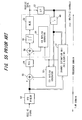
- Fig. 54 is a block diagram illustrating a receiving apparatus in an OFDM transmission system.
- a radio receiver 11 applies frequency conversion processing to a received OFDM carrier signal, and a quadrature demodulator 12 subjects the receive signal to quadrature demodulation processing.
- a guard-interval removal unit 13 removes the guard interval GI from the receive signal after receive-signal synchronization is achieved.
- the resulting receive signal is input to a FFT (Fast Fourier Transform) unit 14.
- the latter executes FFT processing and converts the signal in the time domain to M-number of subcarrier signal (subcarrier sample) values S 1 to S M at an FFT window timing.
- a channel estimation unit 15 performs channel estimate subcarrier by subcarrier using pilot symbols time-division multiplexed on the transmitting side, and a channel compensation unit 16 multiplies the FFT outputs S 1 to S M by respective ones of channel estimation values h 1 to h M of each of the subcarriers. More specifically, using pilot signals, the channel estimation unit 15 estimates phase influence exp(j ⁇ ) and amplitude influence A ascribable to fading of each subcarrier, and the channel compensation unit 16 compensates for fading by multiplying the subcarrier signal components of transmit symbols by exp(-j ⁇ ) and 1/A.
- a parallel/serial converter 17 converts parallel data, which is output from the channel compensation unit 16, to serial data, and a data demodulator 18 demodulates the transmit data.
- a guard interval GI is added onto one item of OFDM symbol data (referred to simply as “symbol data” below) and ISI will not occur even if a multipath delayed wave within the length of a GI symbol exists.
- symbol data referred to simply as “symbol data” below
- the delay time of a delayed wave along an actual transmission path varies greatly, and the delay spread is large, especially outdoors, e.g., 0.2 to 2.0 ps in urban areas and 10 to 20 ps in mountainous areas.
- the conceivable GI length usually cannot provide compensation for 100% of all service areas.
- the transmission performance degrades markedly in multipath delayed propagation that exceeds the guard interval.
- the reason for this is ISI between OFDM symbols and intercarrier interference (ICI) within the same symbol.
- the prior art cited above consists of 1 ⁇ decision feedback equalization for removing the effects of ISI, 2 ⁇ maximum likelihood sequence estimation (MLSE) for removing the effects of ICI from the results of this processing and estimating a transmit-signal sequence, 3 ⁇ Fourier transform processing using a window function that is capable of reducing the number of states in maximum likelihood sequence estimation, and 4 ⁇ channel estimation processing by recursive least squares.
- Fig. 55 is a block diagram of an OFDM receiver according to the prior art.
- an FFT window unit 50 subjects a receive signal to a Fourier transform within a rectangular window in a pilot interval for channel estimation and applies its output to a channel estimation unit 51.
- the latter performs channel estimation using a pilot.
- the FFT window unit 50 changes the window function of the data interval using the pilot. More specifically, (1) when the difference between multipath delay times falls within the guard interval, the usual rectangular window function is used, but (2) if a delay-time difference that exceeds the guard interval is observed, then a smooth window function such as a Hanning window is used in the data interval.
- the FFT window unit 50 performs a Fourier transform in the data interval using a window function.
- a subtractor 55 subtracts an ISI replica, which has been generated by an ISI replica generator 52, from the receive signal that has undergone the Fourier transform. This processing is executed en masse over all subcarriers. This processing section is referred to collectively as a decision feedback equalizer.
- the above-mentioned receive signal from which the ISI has been eliminated is input to an MLSE (maximum likelihood sequence estimation) unit 53, which extracts a transmit-signal sequence of each carrier.
- This equalizer generates transmit-symbol candidates along the frequency axis of symbols at a certain time
- an ICI replica generator 54 generates a replica of the receive signal from the generated plurality of candidates.
- a sequence for which the square of the absolute value of the error between the receive signal and the ICI replica will be minimized is output as a transmit-signal sequence.
- the receiver of Fig. 55 also includes a parallel/serial converter 56, a serial/parallel converter 57, an arithmetic unit 59 and a squaring unit 60.
- the prior art deals with the same topic as the present invention and presents the result of a simulation applied to a wireless LAN system.
- the goal of the prior art is to reduce ISI (intersymbol interference) and ICI (intercarrier interference) ascribable to a delayed wave that has exceeded a guard interval and its characterizing feature is to execute all processing in the frequency domain (namely with the circuitry that follows the FFT on the receiving side). Further, the receive FFT is subjected to time-domain filtering in order to suppress ICI, which spreads into the entirety of the band.
- the demodulated signal undergoes a hard decision by MLSE, soft-decision gain obtained if the signal is the conventional demodulated signal is not acquired at all when concurrent use is made of forward error correction (FEC). That is, the BER performance degrades.
- FEC forward error correction
- MLSE is an exhaustive-search algorithm, the M-number of states in M-ary modulation that must be prepared is equivalent to the multiplier of the carriers observed (since there are two carriers in the case of the prior art, the number of states is the square).
- an object of the present invention is to reduce ISI (intersymbol interference) and ICI (intercarrier interference) ascribable to a delayed wave that has exceeded a guard interval.
- Another object of the present invention is to execute processing to suppress ISI/ICI in the time domain, namely in the circuitry ahead of the FFT on the receiving side, thereby making it possible to exercise control with a fixed amount of calculation independently of the number of M-ary modulation states of the subcarriers and to acquire encoding gain.
- a first receiving apparatus in an OFDM transmission system is applicable to a case where a signal has been transmitted upon making the length of a guard interval added onto an already known symbol (e.g., a pilot symbol) larger than the length of a guard interval added onto a data symbol.
- an already known symbol e.g., a pilot symbol
- a first receiving apparatus comprises 1 ⁇ a receiver for receiving a signal that has been transmitted upon making the length of a guard interval added onto an already known symbol larger than the length of a guard interval added onto a data symbol, and 2 ⁇ a delay-profile measurement unit for measuring a delay profile of a delayed wave having a delay greater than the guard interval of the data symbol by calculating correlation between the received signal and an already known signal.
- the first receiving apparatus further comprises 3 ⁇ an ISI-portion detector for detecting, from the delay profile, a delay-time portion greater than the guard interval of the data as an ISI portion; 4 ⁇ an ISI-replica generator for generating, as an ISI replica, a time-waveform portion of the already known symbol, which conforms to the ISI portion, or a time-waveform portion of the preceding symbol; 5 ⁇ a subtractor for subtracting the ISI replica from the receive signal; 6 ⁇ and a data demodulator for demodulating data by applying FFT processing to the result of subtraction.
- ISI ascribable to a delayed wave that has exceeded the guard interval of data can be reduced and, even if the delay time of the delayed wave exceeds the guard interval of the data, an increase in the BER can be suppressed. Further, since processing is executed to suppress ISI in the time domain, it possible to exercise control with a fixed amount of calculation independently of the number of M-ary modulation states of subcarriers, thereby enabling a reduction in the scale of the hardware.
- the first receiving apparatus further comprises 7 ⁇ means for applying FFT processing to the output of the subtractor and applying IFFT processing to result of demodulation after channel compensation, thereby generating a demodulated-signal restoration replica; and 8 ⁇ means for inserting the demodulated-signal restoration replica into the portion of the subtractor output from which the ISI replica was removed by subtraction.
- the data demodulator demodulates the data by applying FFT processing to the result of insertion.
- both ISI and ICI can be suppressed in the time domain and, even if the delay time of the delayed wave exceeds the guard interval of the data, an increase in the BER can be suppressed. Further, since processing is executed to suppress both ISI and ICI in the time domain, it is possible to exercise control with a fixed amount of calculation independently of the number of M-ary modulation states of the carriers, thereby enabling a reduction in the scale of the hardware.
- a symbol is decided by a hard decision with regard to the result of channel compensation, or a soft decision is rendered by a prescribed quantization bit length, and IFFF processing is applied to the result of the decision to generate the demodulated-signal restoration replica.
- IFFF processing is applied to the result of the decision to generate the demodulated-signal restoration replica.
- a second receiving apparatus in an OFDM transmission system is applicable to a case where the length of a guard interval added onto an already known symbol (e.g., a pilot symbol) and the length of a guard interval added onto a data symbol are equal.
- a second receiving apparatus comprises 1 ⁇ an arithmetic unit for calculating correlation between the received signal and an already known signal; 2 ⁇ means for detecting whether a delayed wave greater than the length of the guard interval has occurred using a correlation value greater than a threshold value; 3 ⁇ means for making "0" a correlation value that is equal to or than the threshold value equal and outputting a delay profile if a delayed wave greater than the length of the guard interval has been generated; 4 ⁇ an ISI-portion detector for detecting, from the delay profile, a delay-time portion greater than the length of the guard interval as an ISI portion; 5 ⁇ an ISI-replica generator for generating, as an ISI replica, a time-waveform portion of the already known symbol, which conforms to the ISI portion, or a time-waveform portion of the previous symbol; 6 ⁇ a subtractor for subtracting the ISI replica from the received signal; and 7 ⁇ a data demodulator for demodulating data by applying FFT processing of the
- the second receiving apparatus further comprises 8 ⁇ means for applying FFT processing to the output of the subtractor and applying IFFT processing to result of demodulation after channel compensation, thereby generating a demodulated-signal restoration replica; and 9 ⁇ means for inserting the demodulated-signal restoration replica into the portion of the subtractor output from which the ISI replica was subtracted.
- the data demodulator demodulates the data by applying FFT processing to the signal resulting from the insertion.
- a third receiving apparatus in an OFDM transmission system according to the present invention is applicable to a case where the length of a guard interval added onto an already known symbol (e.g., a pilot symbol) and the length of a guard interval added onto a data symbol are equal.
- a second receiving apparatus comprises 1 ⁇ means for outputting a delay profile by calculating correlation between a received signal and an already known signal; 2 ⁇ a waveform shaper for detecting, from the delay profile, a delay-time portion greater than the length of the guard interval as an ISI portion, and shaping the waveform of a portion of the received signal that conforms to the ISI portion; 3 ⁇ means for applying FFT processing and channel compensation to the output signal of the waveform shaper and applying IFFT processing to the signal after application of channel compensation to thereby generate a demodulated-signal restoration replica; 4 ⁇ means for adding the demodulated-signal restoration replica to the received signal; and 5 ⁇ a data demodulator for demodulating data by applying FFT processing to the result of addition.
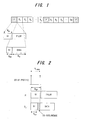
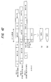
- Fig. 1 is a diagram useful in describing the structure of a pilot symbol (P) and data symbol (D i , where 1 ⁇ i ⁇ m) and transmission frame format according to the present invention.
- the pilot symbol P which is inserted periodically among the data symbols D i , has a guard-interval length different from that of the data symbol.
- the guard-interval length of the pilot symbol P is N GP' the guard-interval length of the data symbol is N GD , and N GP >N GD holds.
- the effective symbol lengths (N U ) are identical as they are decided by the number of FFT points, i.e., the number of subcarriers.
- the guard-interval length N GP in the pilot symbol P is made greater than the conceivable maximum delay profile (maximum delay time of the delayed wave) N ⁇ max .
- the prior art shown in Fig. 55 performs channel estimation using only the front (preamble signal) of transmit data adopted in a wireless LAN system (IEEE 802.11a) and thenceforth uses an RLS (Recursive Least Squares) algorithm.
- the present invention inserts a variable GI length N GP among the pilot symbols P periodically, thereby implementing ISI-free channel estimation without using a convergence algorithm of the kind used in the prior art.
- N GP - N GD samples in the pilot symbol
- Fig. 3 is a block diagram illustrating a receiving apparatus in an OFDM transmission system according to a first embodiment of the present invention.
- signal processing in a time domain is executed before FFT processing
- processing in a frequency domain is executed after FFT processing
- processing in the time domain is executed after IFFT processing.
- the first embodiment illustrates a case where channel estimation / measurement of delay profile using a receive signal (i.e., time waveform) prior to FFT processing on the receiving side is carried out.
- a receiving unit (see the radio receiver 11 and quadrature demodulator 12 in Fig. 54) inputs the receive signal to a guard-interval removal unit 100. It should be noted that the guard-interval length N GP added onto the pilot symbol P is greater than the guard-interval length N GD added onto the data symbol D i (N GP > N GD ).
- the guard-interval removal unit 100 removes the guard interval GI from the receive signal and then inputs the receive signal to a channel estimation unit 101 and a subtractor 102. Since the pilot symbol is an already known signal, an IFFT unit 101a in the channel estimation unit 101 applies IFFT to the subcarrier components of the known pilot symbol to thereby generate a time waveform (replica), and a correlator 101b measures a delay profile by calculating cross correlation between the replica and the received pilot signal portion. In actuality, the correlator 101b extracts N samples of the receive signal, calculates a correlation value upon shifting the replica one sample at a time and thus calculates N samples of values. As a result, a delay profile having peaks at the receive timings of direct and delayed waves is measured.
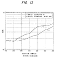
- the delay profile measured by the channel estimation unit 101 is input to a GI-exceed delayed wave detector 103, which performs monitoring to determine whether a delayed wave that has exceeded the guard-interval length N GD of the data symbol Di has been observed. If the delay time N ⁇ max of the delayed wave becomes greater than N GD (N GD ⁇ N ⁇ max ), as shown in Fig. 2, then an ISI replica generator 104 generates an ISI replica corresponding to the portion that exceeds N GD (the shaded portion in Fig. 2), namely an ISI replica corresponding to (N ⁇ max -N GD ) samples, using the pilot symbol or previous data symbol.
- Figs. 4A to 4E are diagrams useful in describing a method of generating an ISI replica.
- a delayed wave B lags behind a direct wave A by N GD or more, and the delay time N ⁇ max satisfies the relation N GD ⁇ N ⁇ max .
- the data symbol D 0 of the direct wave A partially overlaps the pilot symbol P of the delayed wave B and sustains ISI from the pilot symbol P of the delayed wave B. It is necessary, therefore, to remove this portion of the pilot symbol from the receive signal.
- the ISI replica generator 104 cuts the y portion out of the known pilot-signal waveform and generates it as the ISI replica (see the hatched portion in Fig. 4D).
- a first channel compensator 105 multiplies the ISI replica by the channel estimation value to thereby apply channel compensation and inputs the result to the subtractor 102.
- the latter subtracts the ISI replica from the receive signal and inputs the difference to an FFT arithmetic unit 106, which is a stage that follows the direct wave A and delayed wave B (data symbol D1) shown on the left side of Fig. 4E.
- the FFT arithmetic unit 106 applies FFD processing to the entered receive signal to thereby generate data elements on a per-subcarrier basis.
- An FFT arithmetic unit 107 applies FFT processing to the channel estimation signal to thereby generate a channel compensation value for each subcarrier.
- a channel compensator 108 multiplies the result of FFT processing by the channel compensation value subcarrier-by-subcarrier, thereby demodulating the data elements of the number of subcarriers that constitute the data symbol D 0 , and outputs the demodulated data.
- An IFFT arithmetic unit 109 applies IFFT processing to the demodulated data of the number of subcarriers constituting the data symbol D 0 output from the channel compensator 108 and outputs the time-waveform signal of the data symbol D 0 .
- a delay circuit 110 delays this time-waveform signal by a time equivalent to one symbol time Ts and inputs the delayed signal to the ISI replica generator 104.
- a data symbol D1 (see Fig. 4) of the direct wave A partially overlaps the previous data symbol D 0 of the delayed wave B and sustains ISI from the data symbol D 0 of the delayed wave B. It is necessary, therefore, to remove this portion of the data symbol D 0 from the receive signal.
- the time (number of samples) subjected to interference is y. Accordingly, the ISI replica generator 104 cuts the y portion out of the time-waveform signal of the previous data symbol D 0 to generate it as the ISI replica (see the hatched portion in Fig. 4D).
- the first channel compensator 105 multiplies the ISI replica by the channel estimation value to thereby apply channel compensation and inputs the result to the subtractor 102.
- the latter subtracts the ISI replica from the receive signal and inputs the difference to the FFT arithmetic unit 106, which is a stage that follows the direct wave A and delayed wave B (data symbol D 1 ) shown on the right side of Fig. 4E. Processing is subsequently executed in a manner similar to that of the data symbol D 0 .
- ISI replicas are generated and removed from the receive signal and FFT processing is applied, after which channel compensation is applied and each of the data symbols is demodulated and output.
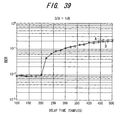
- Figs. 5 to 7 are delayed-wave position (delay time) vs. BER performances (results of simulations) in embodiments inclusive of the one described below. Simulation parameters are shown in Table 1 below.
- BER bit error rate
- D/U is a value that is the result of dividing direct-wave (desired-wave) power D by delayed-wave (undesired-wave) power U.
- Fig. 8 is a modification of the first embodiment and illustrates a case where channel estimation is carried out after FFT. Components identical with those of the first embodiment (Fig. 2) that performs channel estimation before FFT are designated by like reference characters.
- An IFFT unit 101c in a channel estimation unit 101' applies IFFT processing to the result of processing by the FFT 106, thereby generating a receive signal of a time waveform.
- a correlation arithmetic unit 101d measures a delay profile by calculating the correlation between the time waveform of the receive signal and the time waveform (replica) of the known pilot symbol. More specifically, the correlation arithmetic unit 101d extracts N samples of the receive signal, calculates a correlation value upon shifting the replica one sample at a time and thus calculates N samples of values. As a result, a delay profile having peaks at the receive timings of direct and delayed waves is measured. Operation similar to that of the first embodiment is carried out thereafter.
- the description rendered above illustrates a case where there are two paths (direct and delayed waves) and the ISI path is one path.
- the present invention is not limited to the number of paths on which ISI is generated, and it will suffice to calculate replicas the number of which is equivalent to the number of paths on which ISI is produced.
- the number of paths to undergo elimination may be limited by the size (power) thereof or by the magnitude of the delay time.
- the number of paths to undergo elimination is decided by a tradeoff between performances and degree of complexity. Further, the modification of Fig. 8 can also be applied to the embodiments described later.
- Fig. 9 is a block diagram illustrating a receiving apparatus according to a second embodiment. Whereas the first embodiment suppresses only ISI, the second embodiment simultaneously suppresses ICI in addition to ISI.
- Figs. 10A to 10F are diagrams useful in describing the principle of ICI suppression.
- the receive signal shown in Fig. 10B is subjected to FFT processing upon eliminating the the ISI segment y of the delayed wave B shown in Fig. 10A in order to remove ISI.
- each subcarrier component obtained by FFT processing includes distortion ascribable to ICI.
- it will suffice to insert a waveform that will make the delayed wave B smooth over the span of the ISI segment y and periodic as well, as indicated by the dashed line in Fig. 10C.
- the receive signal of Fig. 10B is subjected to FFT processing, as shown in Fig. 10D, after which IFFT processing is applied, thereby providing a continuous signal waveform, as shown in Fig. 10E.
- the delayed wave B will become a continuous periodic waveform, as shown in Fig. 10F.
- An FFT processor 201 applies FFD processing to the receive signal (see Fig. 10B) of data symbol D i , which has entered from the subtractor 102, thereby generating data elements on a per-subcarrier basis.
- a channel compensator 202 multiplies the result of FFT processing by a channel compensation value subcarrier by subcarrier.
- An IFFT processor 203 applies IFFT processing to demodulated data of the number of subcarriers constituting the data symbol D i output from the channel compensator 202 and outputs the time-waveform signal (see Fig. 10E) of data symbol D i .
- a demodulated-signal restoration replica generator 204 cuts out the signal portion of the y segment at the tail end of the time-waveform signal that enters from the IFFT processor 203, thereby generating a demodulated-signal restoration replica (ICI replica), and inputs the replica to a combiner 205.
- the latter combines the demodulated-signal restoration replica with the receive signal (see Fig. 10B) that is output from the subtractor 102, thereby producing a continuous signal waveform, and inputs this waveform to the FFT arithmetic unit 106.
- a delay circuit 206 indicated by the dashed line delays the signal output from the subtractor 102 and inputs the delayed signal to the combiner 205.
- the FFT arithmetic unit 106 applies FFD processing to the combined signal output from the combiner 205 to thereby generate data elements on a per-subcarrier basis, and the channel compensator 108 multiplies the result of FFT processing by the channel compensation value subcarrier-by-subcarrier and outputs the result of channel compensation as a demodulated signal.
- ICI can be inhibited together with ISI.
- the second embodiment suppresses ISI and ICI simultaneously. That is, as shown in Fig. 10D, the receive signal of Fig. 10B is subjected to FFT processing, after which a continuous-signal waveform is obtained, as shown in Fig. 10E, if IFFT processing is applied.
- the tail-end segment y of the continuous-waveform signal of Fig. 10E is cut out and inserted into the segment y at the front end of the receive delayed signal of Fig. 10B, thereby making the delayed wave B a continuous periodic waveform, as shown in Fig. 10F, then the signal of Fig. 10F is subjected to FFT processing to suppress ICI.
- the third embodiment supplements the second embodiment by cutting out the segment y at the front end of the continuous signal waveform of Fig. 10E and uses it as a replica to replace the segment y at the front end of the received desired signal A of Fig. 10B. As a result, demodulation quality can be improved further.
- Fig. 11 is a block diagram illustrating a receiving apparatus according to a third embodiment of the present invention
- Fig. 12 is a diagram useful in describing signal phase of desired waves and of delayed waves of portions A to D.
- a "0" insertion unit 211 inserts "0" into the ISI portion of a desired-wave component of the signal (see signal A in Fig. 12) that is output from the subtractor 102.
- the FFT 201, channel compensator 202 and IFFT unit 203 subject the output signal of the subtractor 102 to FFT processing and channel compensation and apply IFFT processing to the result of demodulation following channel compensation.
- the demodulated-signal restoration replica generator 204 outputs a y segment RC at the front end and y segment RS at the tail end of the signal (see signal C in Fig. 12), which has undergone IFFT processing, as demodulated-signal restoration replicas (restoration replicas).
- An adder 212 adds the restoration replicas RC and RS to the y segments at the front ends of the desired wave and delayed-wave signal (see signal B in Fig. 12), respectively, which are output from the "0" insertion unit 211, and outputs the result.
- the FFT arithmetic unit 106 and channel compensator 108 apply FFT processing and channel compensation to the result of addition (see signal D in Fig. 12) and outputs the demodulated signal.
- the number of ISI samples of "0" insertion is decided under conditions of (a) maximum power path, (b) minimum delay path or (c) a path for which (a) ⁇ (b) is maximum.
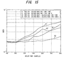
- Fig. 13 is a diagram useful in describing the effects of the third embodiment.
- A represents the performance of the second embodiment and B the performance of the third embodiment.
- D/U 0 dB
- B the performance of the third embodiment.
- Fig. 14 is a modification of the third embodiment.
- This modification has an arrangement in which a number of ICI suppression unit 251 are cascade-connected.
- the ICI suppression unit 251 comprises the IFFT unit 203 for applying IFFT processing to the input signal; the replica generator 204 for generating a restoration replica from the output signal of the IFFT unit 203; the adder 212 for adding the restoration replica to the output signal of the "0" insertion unit 211; the FFT arithmetic unit 106 for applying FFT processing to the result of addition; and the channel compensator 108.
- the number of iterations is two, two of the ICI suppression units 251 are cascade-connected. In general, if the number of iterations is k, k-number of the ICI suppression units 251 are cascade-connected.
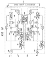
- Fig. 15 is a diagram useful in describing the effects of this modification.
- A1, A2 represent the performances of the second embodiment
- B1, B2 the performances of the third embodiment
- the performance improving effect ascribable to iteration is small.
- a performance substantially equivalent to that within the guard interval is obtained by performing iteration only once.
- Fig. 16 is a block diagram of a diversity arrangement according to a fourth embodiment of the present invention.
- the arrangement of the second embodiment is provided in two branches, ICI is eliminated in each branch using the demodulated-signal restoration replica of the branch having the larger D/U, and the demodulated signals of both branches are subjected to maximum-ratio combining and the result is output, or the demodulated signal of the branch having the larger D/U is selected and output.
- receivers 301, 302 in respective ones of the branches have functions identical with those of the second embodiment, and components identical with those of Fig. 9 are designated by like reference characters.
- This embodiment differs in that the FFT arithmetic units 106, 201 are made a common unit 106, the channel compensators 108, 202 are made a common compensator 108 and the IFFT units 109, 203 are made a common unit 109, and the FFT arithmetic unit 201, channel compensator 202 and IFFT unit 203 are eliminated.
- a demodulated-signal restoration replica selector/generator 303 calculates D/U in each branch based upon delay profiles that enter from the channel estimation units 101 in the receivers 301, 302 of the respective branches, selects the signal that enters from the IFFT unit 109 having the larger D/U, creates a demodulated-signal restoration replica (ICI replica) using the selected signal and inputs the created replica to the combiners 205 of the receivers 301, 302 in each of the branches.
- An antenna diversity selector/combiner 304 subjects the demodulated signals that enter from the receivers 301, 302 of the respective branches to, e.g., maximum-ratio combining and outputs the result.
- the D in D/U indicates the power of the direct wave (desired wave) that enters from the channel estimation unit 101 and that U indicates the power of the delayed wave (ISI portion), which is the undesired wave.
- the power of the ISI portion is low if D/U is large and high if D/U is small.
- the ICI replica signal of the branch having the larger D/U is used (shared) as the ICI replica signal of the branch having the smaller D/U by diversity reception, thereby improving the quality of the demodulated signal of each branch.
- antenna diversity selection/combination similar to that of the prior art is carried out, thereby assuring a stable reception performance under stringent conditions.
- L (>2) branches it will suffice to use the ICI replica of the branch having the maximum D/U.
- the fourth embodiment can be termed a performance improving scheme that employs diversity gain.
- Figs. 17, 18 are receive performances for describing the effects of 2-branch diversity reception.
- Fig. 19 is a block diagram of a receiver according to a fifth embodiment of a diversity arrangement for performing selection-combining or maximum-ratio-combining on a per-subcarrier basis.
- the arrangement of the second embodiment is provided in two branches. It should be noted that, in general, a k-branch implementation can be adopted.
- Receivers 311, 312 in respective ones of the branches have functions identical with those of the second embodiment, and components identical with those of Fig. 9 are designated by like reference characters.
- This embodiment differs in that 1 ⁇ the IFFT unit 109 and delay circuit 110 of the second embodiment are shared by the receivers 311, 312; 2 ⁇ the IFFT unit 203 is shared by the receivers 311, 312; 3 ⁇ a demodulated-signal restoration replica generator 313 is shared by the receivers 311, 312 and is provided ahead of the IFFT unit 203, and the input signals of the branches are subjected to selection-combining or maximum-ratio-combining on a per-subcarrier basis; and 4 ⁇ an antenna diversity selector/combiner 314 is provided, the demodulated signals of the branches are subjected to selection-combining or maximum-ratio-combining and the result is output, and this output signal (demodulated signal) is input to the ISI replica generator 104 via the IFFT unit 109 and delay unit 110.
- Figs. 20A and 20B are diagrams useful in describing the principle of generation of an ISI replica and restoration replica in 2-branch diversity reception.
- the antenna diversity selector/combiner 314 and demodulated-signal restoration replica generator 313 generate an ISI replica and restoration replica, respectively, at which time the signal in the branch having the larger transmission-path estimate value is selected and output carrier by carrier.
- the demodulated-signal restoration replica generator 313 selects the signal of the branch having the larger transmission-path estimation value carrier by carrier in accordance with Equation (1), and the IFFT unit 203 subjects each selected signal of a subcarrier to IFFT processing to thereby output a restoration replica.
- the antenna diversity selector/combiner 314 selects the signal of the branch having the larger transmission-path estimation value in accordance with Equation (2), inputs this signal to a demodulator (not shown) and also to the ISI replica generator 104 via the IFFT unit 109 and delay unit 110.
- the antenna diversity selector/combiner 314 and demodulated-signal restoration replica generator 313 generate an ISI replica and restoration replica, respectively, at which time the signals in the branches are maximum-ratio combined and output using a transmission-path estimation value. That is, when the ISI replica and restoration replica are generated, the receive signals of a plurality of antenna branches are each multiplied by a transmission-path response value, the sum total of the products is normalized by the transmission-path response value and the normalized value is adopted as the replica signal.
- the replica signal based upon maximum-ratio combining is expressed by the equations below using notation similar to that of selection reception, where i represents the symbol number, j the carrier number and k the branch number.
- the ISI replica Z(i,j) is found from the following equation using an (i-1)th symbol X(i-1,j,K), as shown in Fig. 20A: Further, the restoration replica Z(i,j) is found from the following equation using an ith symbol X(i,j,K), as shown in Fig. 20B:
- the demodulated-signal restoration replica generator 313 outputs a signal obtained by maximum-ratio combining on a per-carrier basis in accordance with Equation (4), and the IFFT unit 203 subjects each output signal of a subcarrier to IFFT processing to thereby output a restoration replica.
- the antenna diversity selector/combiner 314 calculates a value normalized by a transmission-path response value in accordance with Equation (3) and inputs the value to a decoder (not shown) and also to the ISI replica generator 104 via the IFFT unit 109 and delay unit 110.
- Fig. 21 is a simulation performance diagram for describing the effects of the fifth embodiment.
- Eb/N0 is plotted along the horizontal axis and BER along the vertical axis.
- C represents the performance of the fifth embodiment in the case of selection reception
- an improvement in performances ascribable to diversity gain is possible even under stringent conditions of low D/U, i.e., high ISI power.
- an improvement in performances branch by branch promises an even greater improvement in performances.
- Fig. 22 is a block diagram illustrating a receiving apparatus according to a sixth embodiment of the present invention. Components identical with those of the second embodiment in Fig. 9 are designated by like reference characters. This embodiment differs in that a symbol hard decision unit 310 is provided between the channel compensator 202 and IFFT unit 203.
- the sixth embodiment is such that in order to suppress distortion due to ICI when an ICI replica is generated, each subcarrier signal subjected to channel compensation after FFT processing undergoes a symbol hard decision in the symbol hard decision unit 310, and IFFT processing is applied to the result of the hard decision to thereby generate the ICI replica. If this expedient is adopted, distortion of the demodulated signal that has sustained ICI distortion can be corrected.
- Fig. 23 is a diagram useful in describing a constellation illustrating the necessity of a hard decision in the sixth embodiment. It is assumed that the data in each subcarrier has undergone QPSK modulation. If distortion does not occur, signal points will exist at the x marks in each quadrant of Fig. 23 in accordance with (00), (01), (10), (11).
- the positions of the signal points shift. For example, the signal point in the first quadrant shifts from the position of the A point to the position of the B point. If an ICI replica is generated under these conditions, a continuous periodic waveform (see Fig. 10F) will not be obtained and the demodulated signal will contain distortion. Accordingly, signal points A, B are subjected to a hard decision and are regarded as being at the ⁇ position in the first quadrant. When IFFT processing is subsequently applied to generate the ICI replica, a continuous periodic waveform (see Fig. 10F) is obtained and the performance is improved.
- Fig. 24 is a block diagram illustrating a receiving apparatus according to a seventh embodiment of the present invention. This embodiment differs from the sixth embodiment of Fig. 22 in that a switch 401 and threshold-value discrimination unit 402 are provided and in that, depending upon the value of D/U, control is performed adaptively to 1 ⁇ create an ICI replica using the result of the symbol hard decision or 2 ⁇ create an IC replica using the result of channel compensation without a hard decision.
- the performance D of the sixth embodiment (Fig. 22) in which the hard decision is rendered is superior to the performance C of the second embodiment (Fig. 9) in which there is no hard decision. Conversely, however, when D/U becomes 1 dB or greater, the performance D of the sixth embodiment (Fig. 22) in which the hard decision is rendered is inferior to the performance C of the second embodiment (Fig. 9) in which there is no hard decision.
- the threshold-value discrimination unit 402 calculates D/U from the powers D, U of the direct and delayed waves, respectively, of the delay profile that enters from the channel estimation unit 101, determines whether the threshold value is equal to or less than or greater than 1 dB. If the threshold value is equal to or less than 1 dB, the result of the hard decision rendered by the symbol hard decision unit 310 is selected by the switch 401 and input to the IFFT unit 203, whereby the ICI replica is generated. On the other hand, if D/U is greater than 1 dB, the result of compensation by the channel compensator 202 is selected by the switch 401 and input to the IFFT unit 203, whereby the ICI replica is generated.
- Fig. 25 is a block diagram illustrating a receiving apparatus according to an eighth embodiment of the present invention. Components identical with those of the second embodiment in Fig. 9 are designated by like reference characters.
- This embodiment differs in that a limiter 410 is provided between the channel compensator 202 and IFFT unit 203, a limit LM is set at the position indicated by the dashed line in Fig. 26, and signal points present in the area indicated by hatching are limited to signal points on the dashed line. If this arrangement is adopted, an equivalent performance is obtained without performing threshold-value discrimination as in Fig. 24.
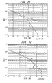
- Figs. 27 to 29 are BER - delay-time performances in cases where D/U is 0, 3 and 5 dB, respectively.
- A is a BER performance of the second embodiment in which there is no limiter
- B is a BER performance of the eighth embodiment.
- the D/U is greater than 3 dB, a performance equivalent to the BER performance of the second embodiment is obtained.
- the channel estimation unit 101 executes channel estimation at the pilot-symbol period and uses the found channel estimation value and delay profile until channel estimation is performed anew.
- the channel estimation value and delay profile fluctuate in dependence upon the magnitude of fading.
- a buffer 111 is provided downstream of the guard-interval removal unit 100 and an interpolator 101e is provided within the channel estimation unit 101, as shown in Fig. 30.
- the correlator 101b of the channel estimation unit 101 calculates first and second channel estimation values at two neighboring pilot-symbol positions and inputs the values to the interpolator 101e.
- the latter linearly interpolates a channel estimation value (which includes the delay time of the delay profile) between the neighboring symbols and outputs the interpolated value at the symbol period.
- the buffer 111 is necessary if this arrangement is adopted, trackability with respect to high-speed fading can be improved.
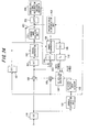
- Fig. 31 is a block diagram illustrating a receiving apparatus according to a ninth embodiment of the present invention, in which components identical with those of the second embodiment of Fig. 9 are designated by like reference characters.
- This embodiment differs in that it is provided with an ISI-replica removal unit 501 for removing an ISI-replica portion from the time-waveform signal of a pilot symbol, an FFT arithmetic unit 502, an ICI fluctuation value calculation unit 503 and a multiplier 504 for compensating for ICI fluctuation.
- an ISI-replica removal unit 501 for removing an ISI-replica portion from the time-waveform signal of a pilot symbol
- an FFT arithmetic unit 502 for removing an ISI-replica portion from the time-waveform signal of a pilot symbol
- an FFT arithmetic unit 502 for removing an ISI-replica portion from the time-waveform signal of a pilot symbol
- an ICI fluctuation value calculation unit 503 for compens
- the waveform signal of the data symbol shown in Fig. 10B from which the ISI segment y has been removed is subjected to FFT processing.
- FFT processing As a consequence, even though an ICI replica is generated and inserted into the ISI segment y of the waveform shown in Fig. 10B, a periodic continuous waveform of the kind shown in Fig. 10F is not obtained accurately and distortion occurs.
- the effect of subjecting the data symbol waveform of Fig. 10B to FFT processing is computed and control is exercised so as to eliminate this effect. More specifically, the ISI-replica removal unit 501 removes the ISI segment y from the time-waveform signal of a known pilot symbol, the FFT arithmetic unit 502 applies FFT processing to the output signal of the ISI-replica removal unit 501, and the ICI fluctuation value calculation unit 503 calculates the difference between the FFT output and known pilot symbol subcarrier by subcarrier and calculates an ICI fluctuation value Aexp(j ⁇ ).
- the multiplier 504 multiplies the output signal of the channel compensator 202 by the inverse performance exp(-j ⁇ )/A of the ICI fluctuation value subcarrier by subcarrier and inputs the product to the IFFT unit 203, which is the next stage.
- an accurate ICI replica can be generated by the demodulated-signal restoration replica generator 204 and a periodic continuous waveform of the kind shown in Fig. 10F is obtained. If the ICI fluctuation value also is linearly interpolated between pilot signals, the tracking performance with respect to high-speed fading is improved.
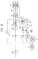
- Fig. 32 is a block diagram illustrating a receiving apparatus according to a tenth embodiment of the present invention, in which components identical with those of the sixth embodiment of Fig. 22 are designated by like reference characters. This embodiment differs in that the symbol hard decision unit 310 provided between the channel compensator 202 and IFFT unit 203 is replaced with a symbol soft decision unit 601.
- 33 to 35 are BER - delay-time performance for a case where quantization bit length of a symbol soft decision has been made two, three and five bits, respectively.
- A is a performance of the eighth embodiment (see Fig. 25) in which quantization bits with a limiter are infinite
- B, C and D are performances of the tenth embodiment when quantization bit length of a symbol soft decision has been made two, three and five, respectively
- E is a hard decision performance.
- Quantization bits ⁇ can be realized by floating-point arithmetic such as DSP (digital signal processor), though problems arise with regard to high-speed operation, etc.
- guard-interval length N GP of a pilot symbol is made greater than guard-interval length N GD of a data symbol, whereby ISI and ICI are reduced and excellent performances are obtained even if a delayed wave that exceeds the guard-interval length N GD of the data symbol is produced.
- the 11 th embodiment is such that in a case where the guard-interval length N GP of a pilot symbol P and the guard-interval length N GD of a data symbol D i are equal, an ISI replica is excluded from the receive signal to reduce ISI and an ICI replica is inserted into the excluded portion to reduce ICI, even if a delayed wave having a delay N ⁇ max greater than the length of the guard interval occurs.
- Fig. 37 is a block diagram illustrating a first receiving apparatus according to the 11th embodiment of the present invention, in which components identical with those of the first embodiment of Fig. 3 are designated by like reference characters. Structurally, the 11 th embodiment differs from the first embodiment in that 1 ⁇ the channel estimation unit 101 of the first embodiment is replaced with channel estimation unit 601; 2 ⁇ the GI-exceed delayed wave detector 103 of the first embodiment is deleted; and 3 ⁇ the channel estimation unit 601 is connected directly to the ISI replica generator 104.
- the channel estimation unit 601 includes a delay-profile measurement unit 601a for creating a delay profile by calculating correlation between the time-waveform signal of a known pilot symbol and the receive signal; a threshold-value discriminator 601b for detecting time positions (direct-wave position T D and delayed-wave position T u ) at peak points greater than a fixed level upon taking noise into consideration; a GI-exceed delayed wave detector 601c for determining whether a peak interval N INT is greater than the guard-interval length N GD and, if the peak interval N INT is greater, for determining whether a delayed wave that exceeds the guard interval has occurred; and a "0" insertion unit 601d which, if a delayed wave greater than the guard-interval length N GD has been produced, makes "0" a correlation value below the threshold value and outputs the delay profile.
- a delay-profile measurement unit 601a for creating a delay profile by calculating correlation between the time-waveform signal of a known pilot symbol and the receive signal
- the ISI replica generator 104 detects the delay-time portion that is greater than the guard interval from the delay profile as an ISI portion and generates a time-waveform portion of a known symbol conforming to the ISI portion or a time-waveform portion of the preceding symbol as an ISI replica. Control identical with that of the first embodiment is thenceforth carried out.
- the performance of the first embodiment also is illustrated for the sake of comparison.
- A is the performance of the 11 th embodiment
- Fig. 41 is a block diagram of a second receiving apparatus according to the 11 th embodiment.
- the 11 th embodiment is provided with an ICI replica generator and the ICI replica is added on in the ISI interval.
- the 1 st to 11 th embodiments set forth above generate an ISI replica and subtract the ISI replica from a receive signal to diminish ISI. Hardware is necessary to generate the ISI replica.
- Fig. 43 is a block diagram illustrating a receiver according to the 12th embodiment of the present invention, in which components identical with those of the sixth embodiment of Fig. 22 are designated by like reference characters. This embodiment differs from the sixth embodiment in that the components 102 to 105 and 109, 110 for generating an ISI replica and subtracting it from the receive signal are deleted and replaced by a waveform shaper 701.
- Fig. 44 is a first embodiment of the waveform shaper 701, which is provided with a select signal generator 711 and selector 712.
- the select signal generator 711 performs monitoring to determine whether a delayed wave greater than the guard interval N GI exists. If such a delayed wave exists and the delay time of the maximum delayed wave is N ⁇ max , the select signal generator 711 outputs a select signal that attains the high level for the duration of the front part (N ⁇ max - N GI ) of an FFT window.
- the selector 712 selects and outputs "0" during the time that the select signal SLL is at the high level, i.e., for the duration of (N ⁇ max - N GI ), and outputs the receive signal at other times.
- the receive signal in which the ISI segment has been made zero (i.e., the signal from which ISI has been cut) by the waveform shaper 701 is processed by the FFT 201, channel compensator 202, symbol hard decision unit 310 and IFFT unit 203, and the restoration replica is generated by the demodulated-signal restoration replica generator 204.
- the adder 205 inserts the restoration replica in the ISI portion of the receive signal (though insertion in the "0" portion of the signal from which ISI has been cut is also permissible).
- the FFT 106 and channel compensator 108 thenceforth apply FFT processing and channel compensation processing and output the demodulated signal.
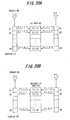
- Fig. 45 shows a second embodiment of the waveform shaper 701, which is provided with a timing signal generator 721, window function generator 722 and multiplier 723.
- the timing signal generator 721 performs monitoring to determine whether a delayed wave greater than the guard interval N GI exists. If such a delayed wave exists and the delay time of the maximum delayed wave is N ⁇ max , the timing signal generator 721 outputs a timing signal that attains the high level for the duration of the front part (N ⁇ max - N GI ) of the FFT window.
- the window function generator 722 generates a window function WF during the time that the timing signal is at the high level.
- Conceivable examples of the window function are a function that increases linearly up to 1.0 for the duration (N ⁇ max - N GI ), as shown in Fig. 46, an exponential function having a time constant (N ⁇ max - N GI ), as shown in Fig. 47, or a triangular function, etc.
- the multiplier 723 multiplies the receive signal by the window function and outputs the result of multiplication.
- the receive signal that has been multiplied by the window function in the waveform shaper 701 is subjected to processing by the FFT 201, channel compensator 202, symbol hard decision unit 310 and IFFT unit 203, and a restoration replica is generated by the demodulated-signal restoration replica generator 204.
- the adder 205 inserts the restoration replica into the ISI portion of the signal that is output from the waveform shaper 701, after which the FFT arithmetic unit 106 and channel compensator 108 apply FFT processing and channel compensation processing and output the demodulated signal.
- a zero insertion unit 702 is provided for inserting zero into the ISI portion of the signal that is output from the waveform shaper 701, and it can be so arranged that the restoration replica is added to the signal in which zero has been inserted.
- the symbol hard decision unit 310 of Fig. 43 need not necessarily be provided.
- the symbol hard decision unit 310 can be replaced by the limiter (Fig. 25) or symbol soft decision unit (Fig. 32). Further, the reduction in amount of processing can be assured by setting a fixed interval beforehand and not adaptively controlling the interval (N ⁇ max - N GI ) over which processing is performed by the waveform shaper.
- the present invention is described with regard to a case where there is single delayed wave.
- the present invention naturally is applicable also to a case where there are two or more delayed waves.
- a delayed wave that is to undergo elimination of ISI and ICI is decided in accordance with 1 ⁇ through 3 ⁇ below.
- ISI ascribable to a delayed wave that has exceeded the guard interval of data can be reduced by making the guard interval of a known signal longer than the guard interval of a pilot. Even if delay time of the delayed wave exceeds the guard interval of the data, an increase in BER can be suppressed. Further, since ISI is suppressed in the time domain, it is possible to exercise control with a fixed amount of calculation independently of the number of M-ary modulation states of the subcarriers, and the scale of the hardware can be reduced.
- both ISI and ICI can be suppressed in the time domain. Even if the delay time of a delayed wave exceeds the guard interval of data, an increase in BER can be suppressed effectively. Further, since processing is executed to suppress both ISI and ICI in the time domain, it is possible to exercise control with a fixed amount of calculation independently of the number of M-ary modulation states of the subcarriers, and the scale of the hardware can be reduced.
- a symbol hard decision is rendered with regard to result of channel compensation, or a soft decision is rendered by a prescribed quantization bit length, and IFFF processing is applied to the result of the decision to generate a demodulated-signal restoration replica.
- a diversity arrangement is adopted and a data demodulated signal is generated using a branch signal having a superior D/U. This makes it possible to improve data decision accuracy.
- a diversity arrangement is adopted, receive signals on a number of branches are selected and combined or subjected to maximum ratio combining, a restoration replica and an ISI replica are generated using the combined signal and ICI and ISI are suppressed. This makes it possible to improve data decision accuracy.
- correlation between a receive signal and known signal is calculated, whether a delayed wave greater than the length of a guard interval has occurred is detected using a correlation value greater than a threshold value, a restoration replica and ISI replica are generated in a case where a delayed wave greater than the length of the guard interval has occurred, and ICI and ISI are suppressed.
- correlation between a receive signal and known signal is calculated and whether a delayed wave greater than the length of a guard interval has occurred is detected.
- the ISI portion of the receive signal is shaped by multiplication by zero or by a window function, a restoration replica is generated using the shaped receive signal and ICI is suppressed.
Priority Applications (1)
| Application Number | Priority Date | Filing Date | Title |
|---|---|---|---|
| EP05000138A EP1523143B1 (fr) | 2002-11-08 | 2003-10-16 | Récepteur dans un système de transmission OFDM |
Applications Claiming Priority (4)
| Application Number | Priority Date | Filing Date | Title |
|---|---|---|---|
| JP2002324952 | 2002-11-08 | ||
| JP2002324952 | 2002-11-08 | ||
| JP2003044519A JP4298320B2 (ja) | 2002-11-08 | 2003-02-21 | Ofdm伝送方式における受信装置 |
| JP2003044519 | 2003-02-21 |
Related Child Applications (1)
| Application Number | Title | Priority Date | Filing Date |
|---|---|---|---|
| EP05000138A Division EP1523143B1 (fr) | 2002-11-08 | 2003-10-16 | Récepteur dans un système de transmission OFDM |
Publications (2)
| Publication Number | Publication Date |
|---|---|
| EP1418720A1 true EP1418720A1 (fr) | 2004-05-12 |
| EP1418720B1 EP1418720B1 (fr) | 2007-07-04 |
Family
ID=32109527
Family Applications (2)
| Application Number | Title | Priority Date | Filing Date |
|---|---|---|---|
| EP03023574A Expired - Fee Related EP1418720B1 (fr) | 2002-11-08 | 2003-10-16 | Récepteur dans un système de transmission OFDM |
| EP05000138A Expired - Fee Related EP1523143B1 (fr) | 2002-11-08 | 2003-10-16 | Récepteur dans un système de transmission OFDM |
Family Applications After (1)
| Application Number | Title | Priority Date | Filing Date |
|---|---|---|---|
| EP05000138A Expired - Fee Related EP1523143B1 (fr) | 2002-11-08 | 2003-10-16 | Récepteur dans un système de transmission OFDM |
Country Status (6)
| Country | Link |
|---|---|
| US (1) | US7362832B2 (fr) |
| EP (2) | EP1418720B1 (fr) |
| JP (1) | JP4298320B2 (fr) |
| KR (1) | KR100922257B1 (fr) |
| CN (1) | CN100499417C (fr) |
| DE (1) | DE60314709T2 (fr) |
Cited By (14)
| Publication number | Priority date | Publication date | Assignee | Title |
|---|---|---|---|---|
| EP1605658A1 (fr) * | 2004-06-09 | 2005-12-14 | Lucent Technologies Inc. | Un système de communication de multiplexage par répartition en fréquences orthogonales efficace en largeur de bande |
| EP1624633A2 (fr) * | 2004-08-04 | 2006-02-08 | Fujitsu Limited | Récepteur MDFO avec suppression d'interférences intersymboles |
| EP1531593A3 (fr) * | 2003-11-11 | 2007-01-24 | NTT DoCoMo, Inc. | Emetteur et récepteur pour MDFO |
| EP1811733A1 (fr) * | 2006-01-20 | 2007-07-25 | Fujitsu Limited | Système de communication sans fil et procédé de communication sans fil avec plusieurs longueurs de l'intervalle de garde |
| EP1821436A1 (fr) * | 2005-01-20 | 2007-08-22 | Matsushita Electric Industrial Co., Ltd. | Dispositif de transmission, dispositif de reception et methode de communication sans fil |
| EP1855404A1 (fr) * | 2005-03-02 | 2007-11-14 | Mitsubishi Electric Corporation | Recepteur |
| EP1858186A1 (fr) * | 2005-03-10 | 2007-11-21 | Matsushita Electric Industrial Co., Ltd. | Appareil recepteur radio et appareil emetteur radio |
| WO2008084634A1 (fr) * | 2007-01-10 | 2008-07-17 | Nec Corporation | Transmission de service de diffusion/multidiffusion multimédia (mbms) dans un système de communication mrof |
| EP1724980A3 (fr) * | 2005-05-20 | 2012-08-22 | Fujitsu Limited | Procédé et dispositif de réception OFDM |
| CN101958853B (zh) * | 2005-01-17 | 2012-11-21 | 夏普株式会社 | 无线电通信设备 |
| TWI395440B (zh) * | 2008-08-04 | 2013-05-01 | Mediatek Inc | 具有動態功率調整之多載波接收機以及動態調整多載波接收機之功率消耗之方法 |
| US8462900B2 (en) | 2008-02-27 | 2013-06-11 | Panasonic Corporation | Reception device, integrated circuit, and reception method |
| EP1737177A3 (fr) * | 2005-06-23 | 2013-10-23 | Kabushiki Kaisha Toshiba | Récepteur pour signal numérique et procédé de réception correspondente. |
| US9906389B2 (en) | 2014-06-30 | 2018-02-27 | Nec Corporation | Receiver, receiving method, and non-transitory computer readable medium |
Families Citing this family (105)
| Publication number | Priority date | Publication date | Assignee | Title |
|---|---|---|---|---|
| JP4121407B2 (ja) * | 2003-03-20 | 2008-07-23 | 富士通株式会社 | Ofdmシンボルを復調する受信機 |
| DE602004026723D1 (de) * | 2003-06-19 | 2010-06-02 | Sony Corp | Funkkommunikationssystem, Empfangseinrichtung und Empfangsverfahren für Mehrträger-Übertragung |
| WO2005055479A1 (fr) * | 2003-12-02 | 2005-06-16 | Matsushita Electric Industrial Co., Ltd. | Appareil de transmission sans fil et procede de suppression d'une puissance pic dans une transmission multiporteuse |
| US7756003B1 (en) | 2004-02-27 | 2010-07-13 | Marvell International Ltd. | Adaptive OFDM transmitter based on carrier frequency offset |
| CA2562218C (fr) * | 2004-04-06 | 2012-01-03 | Michael Stegmair | Dispositif permettant de poser, de maniere amovible, un accessoire d'aide a la traction sur une roue de vehicule presentant une jante et un pneu |
| JP4574210B2 (ja) * | 2004-04-16 | 2010-11-04 | 株式会社エヌ・ティ・ティ・ドコモ | 受信機、送信機および無線通信システム並びにチャネル推定方法 |
| US20060246928A1 (en) * | 2004-04-22 | 2006-11-02 | Hidetoshi Nishino | Synchronization processing apparatus and synchronization processing method |
| RU2006147002A (ru) * | 2004-05-28 | 2008-07-10 | Конинклейке Филипс Электроникс Н.В. (Nl) | Способ обработки сигналов и процессор сигналов в системе ofdm |
| JPWO2006006238A1 (ja) * | 2004-07-14 | 2008-04-24 | 富士通株式会社 | マルチキャリア受信方法及びマルチキャリア受信装置 |
| US7340000B1 (en) * | 2004-08-13 | 2008-03-04 | Cisco Technology, Inc. | Decision feedback equalizer in an OFDM WLAN receiver |
| US7672383B2 (en) * | 2004-09-17 | 2010-03-02 | Qualcomm Incorporated | Noise variance estimation in wireless communications for diversity combining and log-likelihood scaling |
| KR100715913B1 (ko) * | 2004-10-12 | 2007-05-08 | 삼성전자주식회사 | 직교주파수분할다중접속 방식의 이동통신시스템에서레인징 신호 검색 장치 및 방법 |
| US20060083291A1 (en) * | 2004-10-15 | 2006-04-20 | Zheng Hongming | Receiver apparatus, and associated method, for operating upon data communicated in a MIMO, multi-code, MC-CDMA communication system |
| CN100566317C (zh) * | 2004-10-22 | 2009-12-02 | 财团法人工业技术研究院 | 基于频率相关性的相干正交频分复用接收器同步方法与装置 |
| JP4167646B2 (ja) | 2004-11-30 | 2008-10-15 | 株式会社東芝 | Ofdm復調装置 |
| JP3724501B1 (ja) * | 2004-11-30 | 2005-12-07 | 三菱電機株式会社 | 復調装置、ダイバーシチ受信装置および復調方法 |
| EP1830501A1 (fr) * | 2004-12-21 | 2007-09-05 | Matsushita Electric Industrial Co., Ltd. | Dispositif de réception ofdm |
| US20090279420A1 (en) * | 2005-01-11 | 2009-11-12 | Nec Corporation | Base station apparatus, radio transmission system, radio base station program, and timing estimation method |
| US8019032B2 (en) * | 2005-02-04 | 2011-09-13 | Qualcomm Incorporated | Method and system for channel equalization |
| JP4364820B2 (ja) | 2005-03-09 | 2009-11-18 | 株式会社メガチップス | Ofdmダイバーシティ受信装置 |
| WO2006098011A1 (fr) * | 2005-03-16 | 2006-09-21 | Fujitsu Limited | Dispositif de communication radio dans un systeme a entrees multiples et procede d'estimation et de separation de voies |
| KR100690615B1 (ko) | 2005-03-21 | 2007-03-09 | 엘지전자 주식회사 | 직교 주파수 분할 다중화 수신기의 전력 의존 소프트 결정장치 및 그 방법 |
| JP4557160B2 (ja) * | 2005-04-28 | 2010-10-06 | 日本電気株式会社 | 無線通信システム、無線通信装置、受信装置、および無線通信方法 |
| US7660229B2 (en) | 2005-06-20 | 2010-02-09 | Texas Instruments Incorporated | Pilot design and channel estimation |
| CN101218845B (zh) | 2005-07-29 | 2013-02-27 | 松下电器产业株式会社 | 多载波通信中的无线通信基站装置、无线通信移动台装置和导频信号序列分配方法 |
| EP1921785A1 (fr) * | 2005-08-26 | 2008-05-14 | Sharp Kabushiki Kaisha | Appareil de contrôle des communications, terminal de communications, système de communication sans fil et procédé de transmission |
| EP1933488A1 (fr) | 2005-09-16 | 2008-06-18 | Sumitomo Electric Industries, Ltd. | Récepteur, méthode de transmission et système de transmission |
| JP4516505B2 (ja) * | 2005-09-21 | 2010-08-04 | シャープ株式会社 | Ofdm受信装置 |
| WO2007046503A1 (fr) * | 2005-10-21 | 2007-04-26 | Matsushita Electric Industrial Co., Ltd. | Dispositif de suppression d’interférence interporteuse et dispositif de réception utilisant ledit dispositif |
| US7835460B2 (en) * | 2005-10-27 | 2010-11-16 | Qualcomm Incorporated | Apparatus and methods for reducing channel estimation noise in a wireless transceiver |
| KR100728221B1 (ko) * | 2005-12-08 | 2007-06-13 | 한국전자통신연구원 | 터보부호 ofdm 시스템용 반복적 잔류 주파수 위상 보정장치 및 그 방법 |
| JP2007159066A (ja) * | 2005-12-08 | 2007-06-21 | Sanyo Electric Co Ltd | 無線通信装置及び無線通信制御方法 |
| WO2007077608A1 (fr) | 2005-12-28 | 2007-07-12 | Fujitsu Limited | Appareil de communication et procede d'estimation de voie |
| US7813421B2 (en) * | 2006-01-17 | 2010-10-12 | Marvell World Trade Ltd. | Order recursive computation for a MIMO equalizer |
| US7899107B1 (en) | 2006-04-17 | 2011-03-01 | Marvell International Ltd. | Preamble detection using low-complexity cross-correlation |
| US8121105B2 (en) * | 2006-04-25 | 2012-02-21 | Nec Corporation | Pilot signal transmission method and radio communication apparatus |
| US8045927B2 (en) * | 2006-04-27 | 2011-10-25 | Nokia Corporation | Signal detection in multicarrier communication system |
| US7864884B2 (en) * | 2006-04-27 | 2011-01-04 | Nokia Corporation | Signal detection in OFDM system |
| WO2007139145A1 (fr) * | 2006-05-30 | 2007-12-06 | Sharp Kabushiki Kaisha | Récepteur sans fil, système de communication sans fil et procédé de réception sans fil |
| US7991077B1 (en) | 2006-05-31 | 2011-08-02 | Marvell International Ltd. | Preamble detection with multiple receive antennas |
| WO2008001424A1 (fr) * | 2006-06-26 | 2008-01-03 | Kyocera Corporation | dispositif de communication OFDM et procédé de décision de longueur d'intervalle de garde |
| JP4637061B2 (ja) | 2006-06-28 | 2011-02-23 | 富士通株式会社 | 無線送信装置及びガードインターバル挿入方法 |
| JP4929895B2 (ja) * | 2006-07-24 | 2012-05-09 | 富士通株式会社 | 送信装置及びサブフレームの作成方法 |
| KR100752670B1 (ko) | 2006-08-25 | 2007-08-29 | 삼성전자주식회사 | 순방향 에러 정정 디코더의 출력을 이용하여 심볼 값을추정하는 ofdm 시스템, 심볼 추정 장치 및 캐리어사이의 간섭 제거 방법 |
| JP2008099259A (ja) * | 2006-09-14 | 2008-04-24 | Matsushita Electric Ind Co Ltd | データ送信装置及びデータ受信装置 |
| US20080069264A1 (en) * | 2006-09-14 | 2008-03-20 | Tomokazu Sada | Data transmitting apparatus and data receiving apparatus |
| US8588325B2 (en) * | 2007-03-16 | 2013-11-19 | Ntt Docomo, Inc. | Communication system, transmission device, reception device, and communication method |
| JP4782717B2 (ja) * | 2007-03-23 | 2011-09-28 | 富士通株式会社 | 無線フレームの先頭位置検出方法及び装置 |
| JP4928603B2 (ja) * | 2007-04-06 | 2012-05-09 | パナソニック株式会社 | 送信装置及びssb信号形成方法 |
| US7579921B2 (en) | 2007-04-25 | 2009-08-25 | Nec Laboratories America, Inc. | On-off keying-7-phase shift keying modulation system and method for fiber communication |
| CN101350803B (zh) * | 2007-07-16 | 2012-11-28 | 电信科学技术研究院 | 下行数据的传送方法和装置 |
| US20110206031A1 (en) * | 2007-08-06 | 2011-08-25 | Takashi Yoshimoto | Receiver and receiving method |
| US7778318B1 (en) * | 2007-08-15 | 2010-08-17 | Agilent Technologies, Inc. | OFDM gain compression measurement |
| DE102007039786A1 (de) * | 2007-08-23 | 2009-02-26 | Deutsche Telekom Ag | Verfahren und Vorrichtung zur Messung des Antennendiversity-Gewinns in digitalen Funkübertragungssystemen |
| US7773683B2 (en) * | 2007-08-31 | 2010-08-10 | Industrial Technology Research Institute | Method and apparatus for ICI cancellation in communication systems |
| KR101413309B1 (ko) * | 2007-10-08 | 2014-06-27 | 엘지전자 주식회사 | 채널 선택성을 감소시키는 전송기 및 데이터 전송 방법 |
| JP5157430B2 (ja) * | 2007-12-27 | 2013-03-06 | 日本電気株式会社 | 送信装置、送受信装置、送信方法、送受信方法 |
| US20090185630A1 (en) * | 2008-01-23 | 2009-07-23 | Mediatek Inc. | Method and apparatus for estimating the channel impulse response of multi-carrier communicating systems |
| JP5031600B2 (ja) | 2008-01-28 | 2012-09-19 | 京セラ株式会社 | 無線通信方法、無線通信システム、基地局、移動局 |
| CN101499814B (zh) * | 2008-01-30 | 2012-09-05 | 京信通信系统(中国)有限公司 | 用于wcdma系统同频多小区下行的参数测量方法 |
| JP5108940B2 (ja) * | 2008-03-31 | 2012-12-26 | 株式会社日立製作所 | 無線通信システムにおけるタイミング調整方法、受信局、送信局及び無線通信システム |
| US7912142B2 (en) * | 2008-04-04 | 2011-03-22 | Newport Media, Inc. | Double layer maximum ratio combining for an OFDM receiver with inter-carrier-interference cancelling |
| JP5281078B2 (ja) * | 2008-04-11 | 2013-09-04 | パナソニック株式会社 | 受信装置、集積回路、デジタルテレビ受像機、受信方法、及び受信プログラム |
| KR100980498B1 (ko) * | 2008-04-28 | 2010-09-07 | (주)에프씨아이 | 부반송파의 리오더링이 필요하지 않은 ofdm 수신기 및ofdm 신호처리방법 |
| JP2009278448A (ja) * | 2008-05-15 | 2009-11-26 | Fujitsu Microelectronics Ltd | Ofdm受信機およびofdm受信方法 |
| JP5023006B2 (ja) * | 2008-07-09 | 2012-09-12 | 日本放送協会 | Ofdm信号受信装置および中継装置 |
| EP2146470B1 (fr) * | 2008-07-15 | 2012-02-01 | ST-Ericsson SA | Réduction de l'interférence entre porteuses pour signaux multiporteuses |
| JP2010034934A (ja) * | 2008-07-30 | 2010-02-12 | Oki Semiconductor Co Ltd | 伝送路推定方法及び伝送路推定器 |
| KR101576911B1 (ko) * | 2008-09-11 | 2015-12-11 | 삼성전자주식회사 | 세컨더리 시스템의 협력 신호에 기반하는 인지 무선 통신 시스템 |
| JP4626698B2 (ja) * | 2008-09-29 | 2011-02-09 | ソニー株式会社 | 情報処理装置及び方法、表示装置、並びにプログラム |
| CN101729461B (zh) * | 2008-10-20 | 2013-04-24 | 澜起科技(上海)有限公司 | 消除单频干扰及多频干扰的系统及方法 |
| KR100967058B1 (ko) * | 2008-11-21 | 2010-06-29 | 성균관대학교산학협력단 | 무선통신 시스템에서의 개량된 채널 추정 방법 및 채널 추정기 |
| US8396180B2 (en) * | 2008-12-18 | 2013-03-12 | Kawasaki Microelectronics America Inc. | High jitter tolerant phase comparator |
| KR20100070751A (ko) * | 2008-12-18 | 2010-06-28 | 한국전자통신연구원 | 무선 통신 시스템의 채널 추정 방법 및 그 장치 |
| US8761274B2 (en) * | 2009-02-04 | 2014-06-24 | Acorn Technologies, Inc. | Least squares channel identification for OFDM systems |
| KR20110018143A (ko) * | 2009-08-17 | 2011-02-23 | 삼성전자주식회사 | 이동통신 시스템에서 등화기 수신기 및 방법 |
| JP5349206B2 (ja) * | 2009-08-28 | 2013-11-20 | 三菱電機株式会社 | キャリア間干渉除去装置及びキャリア間干渉除去方法 |
| JP5115534B2 (ja) * | 2009-10-14 | 2013-01-09 | 富士通株式会社 | 無線通信システム及び無線通信方法 |
| EP2501061B1 (fr) | 2009-11-09 | 2018-12-26 | Nec Corporation | Appareil de transmission radioélectrique, procédé de transmission radioélectrique, support d'enregistrement et circuit bande de base |
| JP5428788B2 (ja) * | 2009-11-13 | 2014-02-26 | シャープ株式会社 | 受信装置、受信方法、及び受信プログラム |
| JP5371722B2 (ja) * | 2009-12-11 | 2013-12-18 | シャープ株式会社 | 受信装置、受信方法、及び受信プログラム |
| US8335269B2 (en) | 2009-12-16 | 2012-12-18 | Electronics And Telecommunications Research Institute | Apparatus for receiving signals in a communication system based on multicarrier transmission and method for interference cancellation |
| US8254510B2 (en) * | 2009-12-23 | 2012-08-28 | Industrial Technology Research Institute | Apparatus and method for inter-carrier interference cancellation |
| JP5415308B2 (ja) | 2010-01-26 | 2014-02-12 | 京セラ株式会社 | 基地局及び基地局での基準タイミングの調整方法 |
| JP5644475B2 (ja) * | 2010-02-18 | 2014-12-24 | 富士通株式会社 | 受信装置 |
| JP5454236B2 (ja) | 2010-03-05 | 2014-03-26 | 富士通株式会社 | 受信装置および受信方法 |
| JP5454237B2 (ja) | 2010-03-05 | 2014-03-26 | 富士通株式会社 | 受信装置および受信方法 |
| JP2011217191A (ja) * | 2010-03-31 | 2011-10-27 | Fujitsu Ltd | Ofdm信号の受信方法及びその方法を実行する受信装置 |
| JP2012204941A (ja) * | 2011-03-24 | 2012-10-22 | Toshiba Corp | 受信装置および受信方法 |
| JP5812827B2 (ja) * | 2011-11-30 | 2015-11-17 | 三菱電機株式会社 | 受信装置 |
| US9401826B2 (en) * | 2012-02-17 | 2016-07-26 | Sony Corporation | Signal processing unit employing a blind channel estimation algorithm and method of operating a receiver apparatus |
| WO2014006961A1 (fr) * | 2012-07-06 | 2014-01-09 | 日本電気株式会社 | Dispositif et procédé d'estimation de fréquence doppler d'évanouissement |
| WO2014124661A1 (fr) * | 2013-02-12 | 2014-08-21 | Nokia Solutions And Networks Oy | Insertion de zéros pour une réception ofdm sans isi |
| JP6198665B2 (ja) | 2013-07-05 | 2017-09-20 | 三菱電機株式会社 | 受信装置及び受信方法 |
| KR102110841B1 (ko) * | 2013-08-01 | 2020-05-14 | 삼성전자주식회사 | 신호 복조를 위하여 임계값을 적응적으로 설정하는 방법 및 장치 |
| US8891705B1 (en) * | 2013-08-26 | 2014-11-18 | Amlogic Co., Ltd. | Methods for signal processing to reduce inter-symbol-interference |
| US9635508B2 (en) * | 2014-01-14 | 2017-04-25 | The United States Of America As Represented By The Secretary Of The Army | Fast method for wideband spectrum sensing |
| KR101549947B1 (ko) | 2014-02-21 | 2015-09-03 | 국방과학연구소 | Ofdm 레이더 시스템에서의 ici 효과를 제거하는 방법 및 장치 |
| EP3427457B1 (fr) * | 2016-03-11 | 2020-09-09 | Orange | Procédé et dispositif de transmission multiservice avec modulation fc-ofdm et récepteur correspondant |
| CN107276923B (zh) * | 2016-04-07 | 2020-07-28 | 富士通株式会社 | 抗混叠的信道估计装置、方法以及接收机 |
| US10396867B2 (en) * | 2016-11-03 | 2019-08-27 | National Instruments Corporation | Reduced-complexity downlink (DL) signal demodulation using reciprocity reference signals for MIMO wireless communication systems |
| KR102549607B1 (ko) * | 2019-01-28 | 2023-06-29 | 삼성전자주식회사 | 크로스토크 노이즈 및 심볼 간 간섭을 선택적으로 보상할 수 있는 전자 회로 |
| US11611459B1 (en) * | 2021-08-25 | 2023-03-21 | Qualcomm Incorporated | Symbol configuration for single-carrier for frequency domain equalization waveform |
| KR102623191B1 (ko) * | 2022-03-04 | 2024-01-11 | 주식회사 램쉽 | 비대칭 풀두플렉스 신호송수신을 위한 에코제거회로 |
| EP4297353A1 (fr) * | 2022-06-24 | 2023-12-27 | Nxp B.V. | Protocoles de communication de véhicules avec coexistence de canaux et calcul d'interférence entre symboles |
Citations (4)
| Publication number | Priority date | Publication date | Assignee | Title |
|---|---|---|---|---|
| EP0802649A1 (fr) * | 1996-04-19 | 1997-10-22 | ALCATEL BELL Naamloze Vennootschap | Procédé et dispositif utilisant des fonctions de fenêtrage pour réduire les fuites transformateur de Fourier et modem DMT utilisant ce dispositif |
| WO2000036801A1 (fr) * | 1998-12-16 | 2000-06-22 | Telefonaktiebolaget Lm Ericsson (Publ) | Recepteur et methode permettant d'eviter une interference intersymboles dans un systeme de transmission a grande vitesse |
| EP1065855A1 (fr) * | 1999-06-29 | 2001-01-03 | Sony International (Europe) GmbH | Adaptation des intervalles de garde dans un system MDFO |
| WO2001058105A1 (fr) * | 2000-02-07 | 2001-08-09 | At & T Corp. | Systeme et procede pour l'operation conjointe quasi-optimale d'estimation de canal et de detection de donnees dans des systemes cofdm |
Family Cites Families (8)
| Publication number | Priority date | Publication date | Assignee | Title |
|---|---|---|---|---|
| FR2671923B1 (fr) * | 1991-01-17 | 1993-04-16 | France Etat | Dispositif de demodulation coherente de donnees numeriques entrelacees en temps et en frequence, a estimation de la reponse frequentielle du canal de transmission et seuillage, et emetteur correspondant. |
| DE60029687T2 (de) * | 1999-06-22 | 2007-10-18 | Matsushita Electric Industrial Co., Ltd., Kadoma | Symboltaktsynchronisierung in Mehrträgerempfängern |
| JP3116090B1 (ja) * | 1999-09-17 | 2000-12-11 | 郵政省通信総合研究所長 | 通信システム、送信装置、受信装置、送信方法、受信方法、および、情報記録媒体 |
| JP2001103033A (ja) * | 1999-09-30 | 2001-04-13 | Hitachi Denshi Ltd | データ伝送装置 |
| US6693984B1 (en) * | 2000-08-29 | 2004-02-17 | Telefonaktiebolaget Lm Ericsson (Publ) | Method and apparatus for compensating for intersymbol interference in a received signal |
| US7027519B2 (en) * | 2001-02-28 | 2006-04-11 | Mitsubishi Electric Research Laboratories, Inc. | Iterative maximum likelihood channel estimation and signal detection for OFDM systems |
| US7133474B2 (en) * | 2001-07-31 | 2006-11-07 | Motorola, Inc. | Method and system for timing recovery and delay spread estimation in a communication system |
| US7139340B2 (en) * | 2002-06-28 | 2006-11-21 | Hitachi, Ltd. | Robust OFDM carrier recovery methods and apparatus |
-
2003
- 2003-02-21 JP JP2003044519A patent/JP4298320B2/ja not_active Expired - Fee Related
- 2003-10-16 EP EP03023574A patent/EP1418720B1/fr not_active Expired - Fee Related
- 2003-10-16 EP EP05000138A patent/EP1523143B1/fr not_active Expired - Fee Related
- 2003-10-16 US US10/687,203 patent/US7362832B2/en not_active Expired - Fee Related
- 2003-10-16 DE DE60314709T patent/DE60314709T2/de not_active Expired - Lifetime
- 2003-10-30 KR KR1020030076173A patent/KR100922257B1/ko not_active IP Right Cessation
- 2003-11-05 CN CNB2003101141916A patent/CN100499417C/zh not_active Expired - Fee Related
Patent Citations (4)
| Publication number | Priority date | Publication date | Assignee | Title |
|---|---|---|---|---|
| EP0802649A1 (fr) * | 1996-04-19 | 1997-10-22 | ALCATEL BELL Naamloze Vennootschap | Procédé et dispositif utilisant des fonctions de fenêtrage pour réduire les fuites transformateur de Fourier et modem DMT utilisant ce dispositif |
| WO2000036801A1 (fr) * | 1998-12-16 | 2000-06-22 | Telefonaktiebolaget Lm Ericsson (Publ) | Recepteur et methode permettant d'eviter une interference intersymboles dans un systeme de transmission a grande vitesse |
| EP1065855A1 (fr) * | 1999-06-29 | 2001-01-03 | Sony International (Europe) GmbH | Adaptation des intervalles de garde dans un system MDFO |
| WO2001058105A1 (fr) * | 2000-02-07 | 2001-08-09 | At & T Corp. | Systeme et procede pour l'operation conjointe quasi-optimale d'estimation de canal et de detection de donnees dans des systemes cofdm |
Non-Patent Citations (4)
| Title |
|---|
| DUKHYUN KIM ET AL: "Residual ISI cancellation for OFDM with applications to HDTV broadcasting", IEEE JOURNAL ON SELECTED AREAS IN COMMUNICATIONS, IEEE INC. NEW YORK, US, vol. 16, no. 8, October 1998 (1998-10-01), pages 1590 - 1599, XP002159671, ISSN: 0733-8716 * |
| HAZY L ET AL: "Synchronization of OFDM systems over frequency selective fading channels", VEHICULAR TECHNOLOGY CONFERENCE, 1997, IEEE 47TH PHOENIX, AZ, USA 4-7 MAY 1997, NEW YORK, NY, USA,IEEE, US, 4 May 1997 (1997-05-04), pages 2094 - 2098, XP010229167, ISBN: 0-7803-3659-3 * |
| SUYAMA S ET AL: "An OFDM receiver with smoothed FFT-window and RLS-MLSE for fast multipath fading environments with large delay spread", PROCEEDINGS IEEE ISSTA 2002 - IEEE INTERNATIONAL SYMPOSIUM ON SPREAD SPECTRUM TECHNIQUES AND APPLICATIONS, PRAGUE, CZECH REPUBLIC, 2-5 SEPT. 2002, vol. 2, 2 September 2002 (2002-09-02), IEEE, Piscataway, NJ, USA, pages 353 - 357, XP010615490 * |
| YAMAMURA T ET AL: "High mobility OFDM transmission system by a new channel estimation and ISI cancellation scheme using characteristics of pilot symbol inserted OFDM signal", VEHICULAR TECHNOLOGY CONFERENCE, 1999. VTC 1999 - FALL. IEEE VTS 50TH AMSTERDAM, NETHERLANDS 19-22 SEPT. 1999, PISCATAWAY, NJ, USA,IEEE, US, 19 September 1999 (1999-09-19), pages 319 - 323, XP010352958, ISBN: 0-7803-5435-4 * |
Cited By (34)
| Publication number | Priority date | Publication date | Assignee | Title |
|---|---|---|---|---|
| EP1531593A3 (fr) * | 2003-11-11 | 2007-01-24 | NTT DoCoMo, Inc. | Emetteur et récepteur pour MDFO |
| US7480235B2 (en) | 2003-11-11 | 2009-01-20 | Ntt Docomo, Inc. | OFDM transmitter and OFDM receiver |
| EP1605658A1 (fr) * | 2004-06-09 | 2005-12-14 | Lucent Technologies Inc. | Un système de communication de multiplexage par répartition en fréquences orthogonales efficace en largeur de bande |
| EP1624633A2 (fr) * | 2004-08-04 | 2006-02-08 | Fujitsu Limited | Récepteur MDFO avec suppression d'interférences intersymboles |
| EP1624633A3 (fr) * | 2004-08-04 | 2006-10-04 | Fujitsu Limited | Récepteur MDFO avec suppression d'interférences intersymboles |
| CN101958853B (zh) * | 2005-01-17 | 2012-11-21 | 夏普株式会社 | 无线电通信设备 |
| EP1821436A4 (fr) * | 2005-01-20 | 2013-01-09 | Panasonic Corp | Dispositif de transmission, dispositif de reception et methode de communication sans fil |
| EP1821436A1 (fr) * | 2005-01-20 | 2007-08-22 | Matsushita Electric Industrial Co., Ltd. | Dispositif de transmission, dispositif de reception et methode de communication sans fil |
| EP1855404A1 (fr) * | 2005-03-02 | 2007-11-14 | Mitsubishi Electric Corporation | Recepteur |
| EP1855404A4 (fr) * | 2005-03-02 | 2012-11-28 | Mitsubishi Electric Corp | Recepteur |
| EP3322114A1 (fr) * | 2005-03-10 | 2018-05-16 | Panasonic Intellectual Property Corporation of America | Appareil récepteur radio et appareil émetteur radio |
| EP1858186A4 (fr) * | 2005-03-10 | 2014-07-16 | Panasonic Corp | Appareil recepteur radio et appareil emetteur radio |
| US9071495B2 (en) | 2005-03-10 | 2015-06-30 | Panasonic Intellectual Property Corporation Of America | Integrated circuit for controlling radio transmission of ACK/NACK information |
| EP1858186A1 (fr) * | 2005-03-10 | 2007-11-21 | Matsushita Electric Industrial Co., Ltd. | Appareil recepteur radio et appareil emetteur radio |
| US9680683B2 (en) | 2005-03-10 | 2017-06-13 | Panasonic Intellectual Property Corporation Of America | Radio receiver apparatus and radio transmitter apparatus |
| EP3499753A1 (fr) * | 2005-03-10 | 2019-06-19 | Panasonic Intellectual Property Corporation of America | Appareil récepteur radio et appareil émetteur radio |
| EP1724980A3 (fr) * | 2005-05-20 | 2012-08-22 | Fujitsu Limited | Procédé et dispositif de réception OFDM |
| EP1737177A3 (fr) * | 2005-06-23 | 2013-10-23 | Kabushiki Kaisha Toshiba | Récepteur pour signal numérique et procédé de réception correspondente. |
| EP2178258A1 (fr) * | 2006-01-20 | 2010-04-21 | Fujitsu Limited | Système de communication sans fil et procédé de communication sans fil avec plusieurs longueurs de l'intervalle de garde |
| EP1811733A1 (fr) * | 2006-01-20 | 2007-07-25 | Fujitsu Limited | Système de communication sans fil et procédé de communication sans fil avec plusieurs longueurs de l'intervalle de garde |
| US9331874B2 (en) | 2006-01-20 | 2016-05-03 | Fujitsu Limited | Wireless communication system and wireless communication method |
| EP2375665A1 (fr) * | 2006-01-20 | 2011-10-12 | Fujitsu Limited | Système de communication sans fil et procédé de communication sans fil avec plusieurs longueurs de l'intervalle de garde |
| US8724446B2 (en) | 2006-01-20 | 2014-05-13 | Fujitsu Limited | Wireless communication system and wireless communication method |
| EP2375664A1 (fr) * | 2006-01-20 | 2011-10-12 | Fujitsu Limited | Système de communication sans fil et procédé de communication sans fil avec plusieurs longueurs de l'intervalle de garde |
| WO2008084634A1 (fr) * | 2007-01-10 | 2008-07-17 | Nec Corporation | Transmission de service de diffusion/multidiffusion multimédia (mbms) dans un système de communication mrof |
| US8767685B2 (en) | 2007-01-10 | 2014-07-01 | Nec Corporation | Transmission of MBMS in an OFDM communication system |
| US8837376B2 (en) | 2007-01-10 | 2014-09-16 | Nec Corporation | Transmission of MBMS in an OFDM communication system |
| US8750260B2 (en) | 2007-01-10 | 2014-06-10 | Nec Corporation | Transmission of MBMS in an OFDM communication system |
| US9386560B2 (en) | 2007-01-10 | 2016-07-05 | Lenovo Innovations Limited (Hong Kong) | Transmission of MBMS in an OFDM communication system |
| US8416749B2 (en) | 2007-01-10 | 2013-04-09 | Nec Corporation | Transmission of MBMS in an OFDM communication system |
| CN101617485B (zh) * | 2007-01-10 | 2013-03-27 | 日本电气株式会社 | Ofdm通信系统中的mbms的传输 |
| US8462900B2 (en) | 2008-02-27 | 2013-06-11 | Panasonic Corporation | Reception device, integrated circuit, and reception method |
| TWI395440B (zh) * | 2008-08-04 | 2013-05-01 | Mediatek Inc | 具有動態功率調整之多載波接收機以及動態調整多載波接收機之功率消耗之方法 |
| US9906389B2 (en) | 2014-06-30 | 2018-02-27 | Nec Corporation | Receiver, receiving method, and non-transitory computer readable medium |
Also Published As
| Publication number | Publication date |
|---|---|
| DE60314709T2 (de) | 2008-04-17 |
| KR20040041498A (ko) | 2004-05-17 |
| US20040091057A1 (en) | 2004-05-13 |
| JP2004208254A (ja) | 2004-07-22 |
| EP1523143A1 (fr) | 2005-04-13 |
| CN100499417C (zh) | 2009-06-10 |
| DE60314709D1 (de) | 2007-08-16 |
| EP1523143A8 (fr) | 2005-07-06 |
| EP1523143B1 (fr) | 2012-11-21 |
| EP1418720B1 (fr) | 2007-07-04 |
| KR100922257B1 (ko) | 2009-10-15 |
| JP4298320B2 (ja) | 2009-07-15 |
| US7362832B2 (en) | 2008-04-22 |
| CN1499753A (zh) | 2004-05-26 |
Similar Documents
| Publication | Publication Date | Title |
|---|---|---|
| US7362832B2 (en) | Receiving apparatus in OFDM transmission system | |
| JP4523294B2 (ja) | 通信装置 | |
| US7974372B2 (en) | OFDM receiving method and receiving apparatus | |
| EP1478149B1 (fr) | Récepteur multiporteuse | |
| JP4409395B2 (ja) | 伝搬路推定方法及び推定装置 | |
| JP5644475B2 (ja) | 受信装置 | |
| KR100610706B1 (ko) | Ofdm 방식의 수신 장치 | |
| EP1555761A1 (fr) | Appareil et procédé pour l'estimation des interférences et du bruit dans un sytème de communication | |
| US20040165650A1 (en) | Transmitter and receiver | |
| US8363539B2 (en) | OFDM receiver and OFDM receiving method | |
| JP4311132B2 (ja) | Ofdm伝送方式における受信装置 | |
| JP2006262039A (ja) | 伝搬路推定方法及び伝搬路推定装置 | |
| JP3715282B2 (ja) | Ofdm受信装置及びofdm信号の補正方法 | |
| US9385908B2 (en) | Communication apparatus and communication method | |
| JP5308438B2 (ja) | 直交パイロット・パターンに対する干渉推定方法 | |
| KR100800765B1 (ko) | 통신 시스템에서 cinr 추정 장치 및 방법 | |
| WO2007139026A1 (fr) | rÉcepteur et procÉdÉ d'estimation de chemin de propagation | |
| KR100602518B1 (ko) | 직교주파수분할다중 통신 시스템의 채널 추정 방법 및 장치 | |
| JP7324102B2 (ja) | Sc-fde方式の受信装置 | |
| JP2007258794A (ja) | Ofdm受信機における雑音低減方法及びその装置 |
Legal Events
| Date | Code | Title | Description |
|---|---|---|---|
| PUAI | Public reference made under article 153(3) epc to a published international application that has entered the european phase |
Free format text: ORIGINAL CODE: 0009012 |
|
| AK | Designated contracting states |
Kind code of ref document: A1 Designated state(s): AT BE BG CH CY CZ DE DK EE ES FI FR GB GR HU IE IT LI LU MC NL PT RO SE SI SK TR |
|
| AX | Request for extension of the european patent |
Extension state: AL LT LV MK |
|
| 17P | Request for examination filed |
Effective date: 20040421 |
|
| 17Q | First examination report despatched |
Effective date: 20040617 |
|
| AKX | Designation fees paid |
Designated state(s): DE FR GB |
|
| GRAP | Despatch of communication of intention to grant a patent |
Free format text: ORIGINAL CODE: EPIDOSNIGR1 |
|
| 17Q | First examination report despatched |
Effective date: 20040617 |
|
| GRAS | Grant fee paid |
Free format text: ORIGINAL CODE: EPIDOSNIGR3 |
|
| GRAA | (expected) grant |
Free format text: ORIGINAL CODE: 0009210 |
|
| AK | Designated contracting states |
Kind code of ref document: B1 Designated state(s): DE FR GB |
|
| REG | Reference to a national code |
Ref country code: GB Ref legal event code: FG4D |
|
| RIN1 | Information on inventor provided before grant (corrected) |
Inventor name: YOSHIDA, MAKOTO,C/O FUJITSU LIMITED |
|
| REF | Corresponds to: |
Ref document number: 60314709 Country of ref document: DE Date of ref document: 20070816 Kind code of ref document: P |
|
| ET | Fr: translation filed | ||
| PLBE | No opposition filed within time limit |
Free format text: ORIGINAL CODE: 0009261 |
|
| STAA | Information on the status of an ep patent application or granted ep patent |
Free format text: STATUS: NO OPPOSITION FILED WITHIN TIME LIMIT |
|
| 26N | No opposition filed |
Effective date: 20080407 |
|
| PGFP | Annual fee paid to national office [announced via postgrant information from national office to epo] |
Ref country code: DE Payment date: 20141007 Year of fee payment: 12 Ref country code: FR Payment date: 20141008 Year of fee payment: 12 Ref country code: GB Payment date: 20141015 Year of fee payment: 12 |
|
| REG | Reference to a national code |
Ref country code: DE Ref legal event code: R119 Ref document number: 60314709 Country of ref document: DE |
|
| GBPC | Gb: european patent ceased through non-payment of renewal fee |
Effective date: 20151016 |
|
| PG25 | Lapsed in a contracting state [announced via postgrant information from national office to epo] |
Ref country code: GB Free format text: LAPSE BECAUSE OF NON-PAYMENT OF DUE FEES Effective date: 20151016 Ref country code: DE Free format text: LAPSE BECAUSE OF NON-PAYMENT OF DUE FEES Effective date: 20160503 |
|
| REG | Reference to a national code |
Ref country code: FR Ref legal event code: ST Effective date: 20160630 |
|
| PG25 | Lapsed in a contracting state [announced via postgrant information from national office to epo] |
Ref country code: FR Free format text: LAPSE BECAUSE OF NON-PAYMENT OF DUE FEES Effective date: 20151102 |