EP1406263A2 - Aufzeichnungs-/Wiedergabegerät und -verfahren, Eingangs-/Ausgangsgerät und -verfahren, Speichergerät, Übertragungsvorrichtung sowie Informationsverarbeitungsgerät und -verfahren - Google Patents
Aufzeichnungs-/Wiedergabegerät und -verfahren, Eingangs-/Ausgangsgerät und -verfahren, Speichergerät, Übertragungsvorrichtung sowie Informationsverarbeitungsgerät und -verfahren Download PDFInfo
- Publication number
- EP1406263A2 EP1406263A2 EP03078476A EP03078476A EP1406263A2 EP 1406263 A2 EP1406263 A2 EP 1406263A2 EP 03078476 A EP03078476 A EP 03078476A EP 03078476 A EP03078476 A EP 03078476A EP 1406263 A2 EP1406263 A2 EP 1406263A2
- Authority
- EP
- European Patent Office
- Prior art keywords
- information
- data
- recording
- storage apparatus
- transmitting
- Prior art date
- Legal status (The legal status is an assumption and is not a legal conclusion. Google has not performed a legal analysis and makes no representation as to the accuracy of the status listed.)
- Withdrawn
Links
- 238000000034 method Methods 0.000 title claims abstract description 35
- 230000010365 information processing Effects 0.000 title claims description 14
- 230000005540 biological transmission Effects 0.000 title description 26
- 238000012545 processing Methods 0.000 claims description 86
- 238000003672 processing method Methods 0.000 claims description 6
- 238000004891 communication Methods 0.000 description 59
- 238000010586 diagram Methods 0.000 description 50
- 230000006870 function Effects 0.000 description 10
- 230000008878 coupling Effects 0.000 description 6
- 238000010168 coupling process Methods 0.000 description 6
- 238000005859 coupling reaction Methods 0.000 description 6
- 239000000284 extract Substances 0.000 description 6
- 230000001965 increasing effect Effects 0.000 description 5
- 230000005236 sound signal Effects 0.000 description 5
- 239000003990 capacitor Substances 0.000 description 4
- 230000001939 inductive effect Effects 0.000 description 4
- 238000009434 installation Methods 0.000 description 4
- 230000003287 optical effect Effects 0.000 description 3
- 238000006243 chemical reaction Methods 0.000 description 2
- 238000004590 computer program Methods 0.000 description 2
- 230000000694 effects Effects 0.000 description 2
- 238000003780 insertion Methods 0.000 description 2
- 230000037431 insertion Effects 0.000 description 2
- 230000003068 static effect Effects 0.000 description 2
- 239000002699 waste material Substances 0.000 description 2
- 230000003442 weekly effect Effects 0.000 description 2
- 230000005684 electric field Effects 0.000 description 1
- 230000004048 modification Effects 0.000 description 1
- 230000010355 oscillation Effects 0.000 description 1
- 230000000644 propagated effect Effects 0.000 description 1
- 239000000126 substance Substances 0.000 description 1
- 238000012795 verification Methods 0.000 description 1
Images


Classifications
-
- H—ELECTRICITY
- H04—ELECTRIC COMMUNICATION TECHNIQUE
- H04N—PICTORIAL COMMUNICATION, e.g. TELEVISION
- H04N21/00—Selective content distribution, e.g. interactive television or video on demand [VOD]
- H04N21/40—Client devices specifically adapted for the reception of or interaction with content, e.g. set-top-box [STB]; Operations thereof
- H04N21/43—Processing of content or additional data, e.g. demultiplexing additional data from a digital video stream; Elementary client operations, e.g. monitoring of home network or synchronising decoder's clock; Client middleware
- H04N21/431—Generation of visual interfaces for content selection or interaction; Content or additional data rendering
- H04N21/4312—Generation of visual interfaces for content selection or interaction; Content or additional data rendering involving specific graphical features, e.g. screen layout, special fonts or colors, blinking icons, highlights or animations
-
- G—PHYSICS
- G11—INFORMATION STORAGE
- G11B—INFORMATION STORAGE BASED ON RELATIVE MOVEMENT BETWEEN RECORD CARRIER AND TRANSDUCER
- G11B15/00—Driving, starting or stopping record carriers of filamentary or web form; Driving both such record carriers and heads; Guiding such record carriers or containers therefor; Control thereof; Control of operating function
- G11B15/02—Control of operating function, e.g. switching from recording to reproducing
- G11B15/023—Control of operating function, e.g. switching from recording to reproducing remotely controlled
-
- G—PHYSICS
- G11—INFORMATION STORAGE
- G11B—INFORMATION STORAGE BASED ON RELATIVE MOVEMENT BETWEEN RECORD CARRIER AND TRANSDUCER
- G11B15/00—Driving, starting or stopping record carriers of filamentary or web form; Driving both such record carriers and heads; Guiding such record carriers or containers therefor; Control thereof; Control of operating function
- G11B15/02—Control of operating function, e.g. switching from recording to reproducing
- G11B15/05—Control of operating function, e.g. switching from recording to reproducing by sensing features present on or derived from record carrier or container
- G11B15/06—Control of operating function, e.g. switching from recording to reproducing by sensing features present on or derived from record carrier or container by sensing auxiliary features on record carriers or containers, e.g. to stop machine near the end of a tape
- G11B15/07—Control of operating function, e.g. switching from recording to reproducing by sensing features present on or derived from record carrier or container by sensing auxiliary features on record carriers or containers, e.g. to stop machine near the end of a tape on containers
-
- G—PHYSICS
- G11—INFORMATION STORAGE
- G11B—INFORMATION STORAGE BASED ON RELATIVE MOVEMENT BETWEEN RECORD CARRIER AND TRANSDUCER
- G11B15/00—Driving, starting or stopping record carriers of filamentary or web form; Driving both such record carriers and heads; Guiding such record carriers or containers therefor; Control thereof; Control of operating function
- G11B15/02—Control of operating function, e.g. switching from recording to reproducing
- G11B15/16—Control of operating function, e.g. switching from recording to reproducing by sensing presence, absence or position of record carrier or container
- G11B15/17—Control of operating function, e.g. switching from recording to reproducing by sensing presence, absence or position of record carrier or container of container
-
- G—PHYSICS
- G11—INFORMATION STORAGE
- G11B—INFORMATION STORAGE BASED ON RELATIVE MOVEMENT BETWEEN RECORD CARRIER AND TRANSDUCER
- G11B23/00—Record carriers not specific to the method of recording or reproducing; Accessories, e.g. containers, specially adapted for co-operation with the recording or reproducing apparatus ; Intermediate mediums; Apparatus or processes specially adapted for their manufacture
- G11B23/02—Containers; Storing means both adapted to cooperate with the recording or reproducing means
- G11B23/04—Magazines; Cassettes for webs or filaments
- G11B23/08—Magazines; Cassettes for webs or filaments for housing webs or filaments having two distinct ends
- G11B23/087—Magazines; Cassettes for webs or filaments for housing webs or filaments having two distinct ends using two different reels or cores
- G11B23/08707—Details
- G11B23/08714—Auxiliary features
-
- G—PHYSICS
- G11—INFORMATION STORAGE
- G11B—INFORMATION STORAGE BASED ON RELATIVE MOVEMENT BETWEEN RECORD CARRIER AND TRANSDUCER
- G11B27/00—Editing; Indexing; Addressing; Timing or synchronising; Monitoring; Measuring tape travel
- G11B27/10—Indexing; Addressing; Timing or synchronising; Measuring tape travel
- G11B27/102—Programmed access in sequence to addressed parts of tracks of operating record carriers
- G11B27/105—Programmed access in sequence to addressed parts of tracks of operating record carriers of operating discs
-
- G—PHYSICS
- G11—INFORMATION STORAGE
- G11B—INFORMATION STORAGE BASED ON RELATIVE MOVEMENT BETWEEN RECORD CARRIER AND TRANSDUCER
- G11B27/00—Editing; Indexing; Addressing; Timing or synchronising; Monitoring; Measuring tape travel
- G11B27/10—Indexing; Addressing; Timing or synchronising; Measuring tape travel
- G11B27/102—Programmed access in sequence to addressed parts of tracks of operating record carriers
- G11B27/107—Programmed access in sequence to addressed parts of tracks of operating record carriers of operating tapes
-
- G—PHYSICS
- G11—INFORMATION STORAGE
- G11B—INFORMATION STORAGE BASED ON RELATIVE MOVEMENT BETWEEN RECORD CARRIER AND TRANSDUCER
- G11B27/00—Editing; Indexing; Addressing; Timing or synchronising; Monitoring; Measuring tape travel
- G11B27/10—Indexing; Addressing; Timing or synchronising; Measuring tape travel
- G11B27/11—Indexing; Addressing; Timing or synchronising; Measuring tape travel by using information not detectable on the record carrier
-
- G—PHYSICS
- G11—INFORMATION STORAGE
- G11B—INFORMATION STORAGE BASED ON RELATIVE MOVEMENT BETWEEN RECORD CARRIER AND TRANSDUCER
- G11B27/00—Editing; Indexing; Addressing; Timing or synchronising; Monitoring; Measuring tape travel
- G11B27/10—Indexing; Addressing; Timing or synchronising; Measuring tape travel
- G11B27/34—Indicating arrangements
-
- G—PHYSICS
- G11—INFORMATION STORAGE
- G11B—INFORMATION STORAGE BASED ON RELATIVE MOVEMENT BETWEEN RECORD CARRIER AND TRANSDUCER
- G11B33/00—Constructional parts, details or accessories not provided for in the other groups of this subclass
- G11B33/10—Indicating arrangements; Warning arrangements
-
- H—ELECTRICITY
- H04—ELECTRIC COMMUNICATION TECHNIQUE
- H04N—PICTORIAL COMMUNICATION, e.g. TELEVISION
- H04N21/00—Selective content distribution, e.g. interactive television or video on demand [VOD]
- H04N21/40—Client devices specifically adapted for the reception of or interaction with content, e.g. set-top-box [STB]; Operations thereof
- H04N21/43—Processing of content or additional data, e.g. demultiplexing additional data from a digital video stream; Elementary client operations, e.g. monitoring of home network or synchronising decoder's clock; Client middleware
- H04N21/431—Generation of visual interfaces for content selection or interaction; Content or additional data rendering
- H04N21/4312—Generation of visual interfaces for content selection or interaction; Content or additional data rendering involving specific graphical features, e.g. screen layout, special fonts or colors, blinking icons, highlights or animations
- H04N21/4314—Generation of visual interfaces for content selection or interaction; Content or additional data rendering involving specific graphical features, e.g. screen layout, special fonts or colors, blinking icons, highlights or animations for fitting data in a restricted space on the screen, e.g. EPG data in a rectangular grid
-
- H—ELECTRICITY
- H04—ELECTRIC COMMUNICATION TECHNIQUE
- H04N—PICTORIAL COMMUNICATION, e.g. TELEVISION
- H04N21/00—Selective content distribution, e.g. interactive television or video on demand [VOD]
- H04N21/40—Client devices specifically adapted for the reception of or interaction with content, e.g. set-top-box [STB]; Operations thereof
- H04N21/43—Processing of content or additional data, e.g. demultiplexing additional data from a digital video stream; Elementary client operations, e.g. monitoring of home network or synchronising decoder's clock; Client middleware
- H04N21/432—Content retrieval operation from a local storage medium, e.g. hard-disk
- H04N21/4325—Content retrieval operation from a local storage medium, e.g. hard-disk by playing back content from the storage medium
-
- H—ELECTRICITY
- H04—ELECTRIC COMMUNICATION TECHNIQUE
- H04N—PICTORIAL COMMUNICATION, e.g. TELEVISION
- H04N21/00—Selective content distribution, e.g. interactive television or video on demand [VOD]
- H04N21/40—Client devices specifically adapted for the reception of or interaction with content, e.g. set-top-box [STB]; Operations thereof
- H04N21/43—Processing of content or additional data, e.g. demultiplexing additional data from a digital video stream; Elementary client operations, e.g. monitoring of home network or synchronising decoder's clock; Client middleware
- H04N21/433—Content storage operation, e.g. storage operation in response to a pause request, caching operations
- H04N21/4334—Recording operations
-
- H—ELECTRICITY
- H04—ELECTRIC COMMUNICATION TECHNIQUE
- H04N—PICTORIAL COMMUNICATION, e.g. TELEVISION
- H04N21/00—Selective content distribution, e.g. interactive television or video on demand [VOD]
- H04N21/40—Client devices specifically adapted for the reception of or interaction with content, e.g. set-top-box [STB]; Operations thereof
- H04N21/43—Processing of content or additional data, e.g. demultiplexing additional data from a digital video stream; Elementary client operations, e.g. monitoring of home network or synchronising decoder's clock; Client middleware
- H04N21/443—OS processes, e.g. booting an STB, implementing a Java virtual machine in an STB or power management in an STB
-
- H—ELECTRICITY
- H04—ELECTRIC COMMUNICATION TECHNIQUE
- H04N—PICTORIAL COMMUNICATION, e.g. TELEVISION
- H04N21/00—Selective content distribution, e.g. interactive television or video on demand [VOD]
- H04N21/40—Client devices specifically adapted for the reception of or interaction with content, e.g. set-top-box [STB]; Operations thereof
- H04N21/47—End-user applications
- H04N21/472—End-user interface for requesting content, additional data or services; End-user interface for interacting with content, e.g. for content reservation or setting reminders, for requesting event notification, for manipulating displayed content
- H04N21/47214—End-user interface for requesting content, additional data or services; End-user interface for interacting with content, e.g. for content reservation or setting reminders, for requesting event notification, for manipulating displayed content for content reservation or setting reminders; for requesting event notification, e.g. of sport results or stock market
-
- H—ELECTRICITY
- H04—ELECTRIC COMMUNICATION TECHNIQUE
- H04N—PICTORIAL COMMUNICATION, e.g. TELEVISION
- H04N21/00—Selective content distribution, e.g. interactive television or video on demand [VOD]
- H04N21/40—Client devices specifically adapted for the reception of or interaction with content, e.g. set-top-box [STB]; Operations thereof
- H04N21/47—End-user applications
- H04N21/482—End-user interface for program selection
-
- H—ELECTRICITY
- H04—ELECTRIC COMMUNICATION TECHNIQUE
- H04N—PICTORIAL COMMUNICATION, e.g. TELEVISION
- H04N5/00—Details of television systems
- H04N5/76—Television signal recording
- H04N5/78—Television signal recording using magnetic recording
- H04N5/782—Television signal recording using magnetic recording on tape
-
- G—PHYSICS
- G11—INFORMATION STORAGE
- G11B—INFORMATION STORAGE BASED ON RELATIVE MOVEMENT BETWEEN RECORD CARRIER AND TRANSDUCER
- G11B2220/00—Record carriers by type
- G11B2220/20—Disc-shaped record carriers
- G11B2220/21—Disc-shaped record carriers characterised in that the disc is of read-only, rewritable, or recordable type
- G11B2220/213—Read-only discs
-
- G—PHYSICS
- G11—INFORMATION STORAGE
- G11B—INFORMATION STORAGE BASED ON RELATIVE MOVEMENT BETWEEN RECORD CARRIER AND TRANSDUCER
- G11B2220/00—Record carriers by type
- G11B2220/20—Disc-shaped record carriers
- G11B2220/25—Disc-shaped record carriers characterised in that the disc is based on a specific recording technology
- G11B2220/2508—Magnetic discs
- G11B2220/2512—Floppy disks
-
- G—PHYSICS
- G11—INFORMATION STORAGE
- G11B—INFORMATION STORAGE BASED ON RELATIVE MOVEMENT BETWEEN RECORD CARRIER AND TRANSDUCER
- G11B2220/00—Record carriers by type
- G11B2220/20—Disc-shaped record carriers
- G11B2220/25—Disc-shaped record carriers characterised in that the disc is based on a specific recording technology
- G11B2220/2525—Magneto-optical [MO] discs
- G11B2220/2529—Mini-discs
-
- G—PHYSICS
- G11—INFORMATION STORAGE
- G11B—INFORMATION STORAGE BASED ON RELATIVE MOVEMENT BETWEEN RECORD CARRIER AND TRANSDUCER
- G11B2220/00—Record carriers by type
- G11B2220/20—Disc-shaped record carriers
- G11B2220/25—Disc-shaped record carriers characterised in that the disc is based on a specific recording technology
- G11B2220/2537—Optical discs
- G11B2220/2545—CDs
-
- G—PHYSICS
- G11—INFORMATION STORAGE
- G11B—INFORMATION STORAGE BASED ON RELATIVE MOVEMENT BETWEEN RECORD CARRIER AND TRANSDUCER
- G11B2220/00—Record carriers by type
- G11B2220/20—Disc-shaped record carriers
- G11B2220/25—Disc-shaped record carriers characterised in that the disc is based on a specific recording technology
- G11B2220/2537—Optical discs
- G11B2220/2562—DVDs [digital versatile discs]; Digital video discs; MMCDs; HDCDs
-
- G—PHYSICS
- G11—INFORMATION STORAGE
- G11B—INFORMATION STORAGE BASED ON RELATIVE MOVEMENT BETWEEN RECORD CARRIER AND TRANSDUCER
- G11B2220/00—Record carriers by type
- G11B2220/60—Solid state media
- G11B2220/65—Solid state media wherein solid state memory is used for storing indexing information or metadata
- G11B2220/652—Solid state media wherein solid state memory is used for storing indexing information or metadata said memory being attached to the recording medium
- G11B2220/655—Memory in cassette [MIC]
-
- G—PHYSICS
- G11—INFORMATION STORAGE
- G11B—INFORMATION STORAGE BASED ON RELATIVE MOVEMENT BETWEEN RECORD CARRIER AND TRANSDUCER
- G11B2220/00—Record carriers by type
- G11B2220/60—Solid state media
- G11B2220/65—Solid state media wherein solid state memory is used for storing indexing information or metadata
- G11B2220/652—Solid state media wherein solid state memory is used for storing indexing information or metadata said memory being attached to the recording medium
- G11B2220/657—Memory in disc [MID]
-
- G—PHYSICS
- G11—INFORMATION STORAGE
- G11B—INFORMATION STORAGE BASED ON RELATIVE MOVEMENT BETWEEN RECORD CARRIER AND TRANSDUCER
- G11B2220/00—Record carriers by type
- G11B2220/90—Tape-like record carriers
-
- H—ELECTRICITY
- H04—ELECTRIC COMMUNICATION TECHNIQUE
- H04N—PICTORIAL COMMUNICATION, e.g. TELEVISION
- H04N5/00—Details of television systems
- H04N5/44—Receiver circuitry for the reception of television signals according to analogue transmission standards
- H04N5/445—Receiver circuitry for the reception of television signals according to analogue transmission standards for displaying additional information
-
- H—ELECTRICITY
- H04—ELECTRIC COMMUNICATION TECHNIQUE
- H04N—PICTORIAL COMMUNICATION, e.g. TELEVISION
- H04N5/00—Details of television systems
- H04N5/76—Television signal recording
- H04N5/84—Television signal recording using optical recording
- H04N5/85—Television signal recording using optical recording on discs or drums
Definitions
- This invention relates to recording/reproduction apparatus, recording/reproduction methods, input/output apparatus, input/output methods, storage apparatus, information transmitting apparatus, information processing apparatus and information processing methods. More particularly, but not exclusively, the invention relates to recording/reproduction apparatus, recording/reproduction methods, input/output apparatus, input/output methods, storage apparatus, information transmitting apparatus, information processing apparatus and information processing methods that allow an index to data stored in a recording medium to be obtained with ease.
- Cassette tapes and optical discs used in recording/reproduction apparatuses such as a VTR (Video Tape Recorder) and an optical-disc drive for recording and reproducing images and sounds are normally organized and controlled by utilizing index cards each used for recording an index to data recorded in the cassette tape or the optical disc such as information on the data including a recording date and a recording time of the data.
- index cards each used for recording an index to data recorded in the cassette tape or the optical disc such as information on the data including a recording date and a recording time of the data.
- an index card is coated with paste on the rear surface thereof which allows the index card to be stuck to a cassette tape or a disc. The user writes down information on data recorded in a cassette tape or a disk including a recording date and a recording time on such an index card and then sticks the index card on the cassette tape or the disc.
- an electronic apparatus having a function known as a tape navigation is available.
- Such an electronic apparatus is used for rewinding a cassette tape to a start position when the cassette tape is mounted on the main body of a recording/reproduction apparatus or for positioning the head employed in the recording/reproduction apparatus at the start position of a disc when the disc is mounted on the main body of a recording/reproduction apparatus. Then, a reproduction operation is once carried out in order to display some of the contents of the cassette tape or the disc.
- a seal with a bar code of the serial number of a cassette tape printed thereon is stuck to the cassette tape.
- the seal can then be used for identifying the cassette tape.
- an index to data recorded in each cassette tape can be stored in a host/target apparatus. When the cassette tape is mounted on the host/target apparatus, an index to data recorded in the cassette tape is displayed.
- rental data is controlled typically by using a ledger or a PC.
- a bar code representing control information such as the serial number of a cassette tape or a disc is printed on a label such as a seal which is then stuck to the cassette tape or the disc.
- the user may forget the contents of the recording medium such as a cassette tape.
- the user verifies the contents of the cassette tape by playing back, rewinding or fast feeding the tape and then enter information on data recorded in the cassette tape including a recording date and a recording time, giving rise to a problem of cumbersome work.
- a preferred form of implementation of the present invention described hereinbelow seeks to provide a recording/reproduction apparatus, a recording/reproduction method, an input/output apparatus, an input/output method, a storage apparatus and an information transmitting apparatus that allow cassette tapes and discs to be controlled with ease and allow various kinds of information on cassette tapes and discs to be obtained.
- the preferred form of implementation of the invention provides a recording/reproduction apparatus characterized by including:
- the preferred form of implementation of the invention also provides a recording/reproduction method characterized by including the steps of:
- the preferred form of implementation of the invention also provides an input/output apparatus characterized by including:
- the preferred form of implementation of the invention also provides an input/output method characterized by including the steps of:
- the preferred form of implementation of the invention also provides a storage apparatus for storing information as well as transmitting and receiving information to and from an external apparatus, the storage apparatus characterized by including:
- the preferred form of implementation of the invention also provides an information processing apparatus characterized by including:
- the preferred form of implementation of the invention also provides an information processing method characterized by including:
- the preferred form of implementation of the invention also provides an information transmitting apparatus characterized by including:
- a recording/reproduction apparatus for recording and reproducing data into and from a recording-medium assembly having a storage apparatus mounted thereon for storing predetermined information
- the recording/reproduction apparatus comprises:
- the recordin g/reproduction apparatus is characterized in that the recording/reproduction apparatus further has a medium accommodating means (implemented typically by a compartment 93 shown in Fig. 9) for accommodating the recording-medium assembly and the switching means switches the information transmitting/receiving means from one to another in accordance with whether or not the recording-medium assembly exists in the medium accommodating means.
- a medium accommodating means (implemented typically by a compartment 93 shown in Fig. 9) for accommodating the recording-medium assembly and the switching means switches the information transmitting/receiving means from one to another in accordance with whether or not the recording-medium assembly exists in the medium accommodating means.
- the recording/reproduction apparatus is characterized in that the recording/reproduction apparatus further has a power supplying means (implemented typically by the antennas 22-1 and 22-2 shown in Fig. 9) for supplying power to the storage apparatus.
- a power supplying means (implemented typically by the antennas 22-1 and 22-2 shown in Fig. 9) for supplying power to the storage apparatus.
- the recording/reproduction apparatus is characterized in that the storage apparatus comprises:
- an input/output apparatus is characterized in that the apparatus comprises:
- the input/output apparatus described in claim 10 is characterized in that the apparatus comprises an information updating means (implemented typically by the microcomputer 27 shown in Fig. 2) for updating the information received through the information transmitting/receiving means and stored in the storage apparatus.
- an information updating means (implemented typically by the microcomputer 27 shown in Fig. 2) for updating the information received through the information transmitting/receiving means and stored in the storage apparatus.
- a storage apparatus for storing information as well as transmitting and receiving information to and from an external apparatus is characterized in that the apparatus comprises:
- an information processing apparatus is characterized by comprising:
- an information transmitting apparatus for transmitting data and predetermined information to a recording/reproduction apparatus for recording or reproducing the data into and from a recording-medium assembly on which a storage apparatus for storing the predetermined information is mounted is characterized in that the information transmitting apparatus comprises:
- an information storage apparatus comprises:
- Fig. 1 is a block diagram showing a typical configuration of a non-contact-type memory card 1 to which the storage apparatus provided by the present invention is applied.
- the non-contact-type memory card 1 is referred to hereafter simply as a memory card.
- An antenna 2 employed in the memory card 1 receives an electric wave from a non-contact-memory-card reader/writer 21 to be described alter.
- the non-contact-memory-card reader/writer 21 is referred to hereafter simply as a reader/writer.
- the antenna 2 supplies a signal representing the electric wave received thereby to a tuning circuit 3 and a power-supply circuit 12.
- the tuning circuit 3 extracts only a signal with a carrier frequency for use in communication between the memory card 1 and the reader/writer 21 from the signal supplied thereto by the antenna 2.
- An amplifier circuit 4 amplifies a signal supplied thereto by the tuning circuit 3 to a predetermined signal level, outputting the amplified signal to a demodulation circuit 5.
- the demodulation circuit 5 demodulates the amplified signal which was modulated at the carrier frequency, producing data conveyed by the modulated signal.
- a communication control circuit 6 carries out mode switching so as to allow a signal to be supplied by the demodulation circuit 5 to a microcomputer 7 or a signal to be supplied by the microcomputer 7 to a modulation circuit 10.
- the microcomputer 7 controls other components by executing a control program stored in a ROM (Read-Only Memory) unit 8.
- the microcomputer 7 also selects information, which needs to be stored in memory, from data received from the demodulation circuit 5 by way of the communication control circuit 6, supplying the information to an EEPROM (Electrically Erasable and Programmable Read-Only Memory) unit 9.
- EEPROM Electrical Erasable and Programmable Read-Only Memory
- the EEPROM unit 9 stores the information supplied thereto by the microcomputer 7.
- the modulation circuit 10 uses data supplied thereto by the microcomputer 7 by way of the communication control circuit 6 for modulating a signal having a carrier frequency.
- An amplifier circuit 11 amplifies the carrier-frequency signal modulated by the modulation circuit 10 to a level required in the communication with the reader/writer 21.
- the antenna 2 transmits the carrier-frequency signal amplified by the amplifier circuit 11 as an electric wave.
- the tuning circuit 3 extracts only a signal with a predetermined carrier frequency from the electric signal supplied by the antenna 2, supplying the extracted carrier-frequency signal to the amplifier circuit 4.
- the amplifier circuit 4 amplifies the carrier-frequency signal supplied thereto by the tuning circuit 3 to a predetermined signal level, supplying the amplified signal to the demodulation circuit 5.
- the demodulation circuit 5 demodulates the amplified signal supplied thereto by the amplifier circuit 4, supplying a demodulated signal to the communication control circuit 6.
- the communication control circuit 6, which has been switched to a reception mode at that time, converts the demodulated signal received from the demodulation circuit 5 into digital data to be supplied to the microcomputer 7.
- the microcomputer 7 forms a judgment as to whether or not the digital data supplied thereto by the communication control circuit 6 is data to be stored in the EEPROM unit 9 by the microcomputer 7. Depending on the outcome of the judgment, the digital data may be supplied to the EEPROM unit 9 to be stored therein.
- the electrical signal generated by the antenna 2 is also supplied to the power-supply circuit 12.
- the power-supply circuit 12 fetches energy from the electrical signal supplied thereto by electromagnetic coupling with a carrier transmitted from the reader/writer 21, supplying power to components employed in the memory card 1. In this way, power can be supplied by an external source to the memory card 1.
- the modulation circuit 10 uses the data received from the communication control circuit 6 to modulate a signal having a carrier frequency, supplying a modulated signal to the amplifier circuit 11.
- the amplifier circuit 11 amplifies the modulated signal supplied thereto by the modulation circuit 10 to a level required in the communication with the reader/writer 21. A signal amplified by the amplifier circuit 11 is then supplied to the antenna 2.
- Fig. 2 is a block diagram showing a typical configuration of a non-contact-type memory-card reader/writer to which the input/output apparatus provided by the present invention is applied.
- An antenna 22 shown in the figure transmits and receives a signal to and from the memory card 1.
- the signal has a predetermined carrier frequency which is required in the communication between the reader/writer 21 and the memory card 1.
- the reader/writer 21 also generates a magnetic field for supplying power to the memory card 1.
- a tuning circuit 23 extracts only a signal with a carrier frequency for use in the communication between the memory card 1 and the reader/writer 21 from the signal supplied by the antenna 22.
- An amplifier circuit 24 amplifies a signal supplied thereto by the tuning circuit 23 to a predetermined signal level, outputting the amplified signal to a demodulation circuit 25.
- the demodulation circuit 25 demodulates the amplified signal which was modulated at the carrier frequency, producing data conveyed by the modulated signal.
- a communication control circuit 26 carries out mode switching so as to allow a signal to be supplied by the demodulation circuit 25 to a microcomputer 27 or a signal to be supplied by the microcomputer 27 to a modulation circuit 30.
- the microcomputer 27 controls other components by executing a control program stored in a ROM (Read-Only Memory) unit 28.
- the microcomputer 27 also selects information, which needs to be stored in memory, from data received from the demodulation circuit 25 by way of the communication control circuit 26, supplying the information to a RAM (Random-Access Memory) unit 29.
- the RAM unit 29 stores the information supplied thereto by the microcomputer 27.
- the modulation circuit 30 uses data supplied thereto by the microcomputer 27 by way of the communication control circuit 26 for modulating a signal having a carrier frequency.
- An amplifier circuit 31 amplifies the carrier-frequency signal modulated by the modulation circuit 30 to a level required in the communication with the memory card 1.
- the antenna 22 transmits the carrier-frequency signal amplified by the amplifier circuit 31 as an electric wave.
- the demodulation circuit 25 demodulates the amplified signal supplied thereto by the amplifier circuit 24, supplying a demodulated signal to the communication control circuit 26.
- the communication control circuit 26 switches the operating mode to a reception mode, converting the demodulated signal received from the demodulation circuit 25 into digital data to be supplied to the microcomputer 27.
- the microcomputer 27 stores the digital data in the RAM unit 29 prior to transmission to an external circuit not shown in the figure through a communication line 32.
- the following is description of a case in which a data-transmission request is issued to request that predetermined data be transmitted from the reader/writer 21 to the memory card 1.
- the data to be transmitted to the memory card 1 is received from the external circuit by the microcomputer 27 by way of the communication line 32.
- the microcomputer 27 supplies the data transmitted thereto from the external circuit by way of the communication line 32 or data already stored in the RAM unit 29 to the communication control circuit 26.
- the communication control circuit 26 converts the data supplied thereto by the microcomputer 27 into an analog signal, supplying the analog signal to the modulation circuit 30.
- the modulation circuit 30 uses the analog signal received from the communication control circuit 26 to modulate a signal having a carrier frequency, supplying a modulated signal to the amplifier circuit 31.
- the amplifier circuit 31 amplifies the modulated signal supplied thereto by the modulation circuit 30 to a level required in the communication with the memory card 1. A signal amplified by the amplifier circuit 31 is then supplied to the antenna 22 for transmission to the memory card 1.
- the signal transmitted through the antenna 22 is received by the antenna 2 employed in the memory card 1 to be finally stored in the EEPROM unit 9 as described above.
- data can be exchanged between the memory card 1 and the reader/writer 21.
- Fig. 3 is a diagram showing a state in which a memory card 1 shown in Fig. 1 is mounted in each of dents 101 and 102 provided on an case of a cassette 100.
- Fig. 4 is a diagram showing a state in which, even if a cassette 100 having a memory card 1 mounted therein is not set in a VTR 41, by merely bringing the cassette 100 to a location in close proximity to the VTR 41, communication between the VTR 41 and the cassette 100 can be established, allowing data stored in the memory card 1 to be displayed on a screen of a television receiver 42 connected to the VTR 41.
- the VTR 41 is provided with a reader/writer 21 shown in Fig. 2.
- the reader/writer 21 is installed on the VTR 41 so that the antenna 22 of the reader/writer 21 is directed to the outside of the VTR 41.
- communication can be established between the memory card 1 mounted on the cassette 100 and the reader/writer 21 installed on VTR 41, allowing the reader/writer 21 to read out data stored in the memory card 1.
- the data read out from the memory card 1 is then supplied to the television receiver 42 to be displayed on a screen thereof.
- the television receiver 42 displays data stored in the memory card 1.
- the power supply is turned on and the television receiver 42 is switched to a mode to receive a video/audio signal from the VTR 41 and to display an image supplied by the VTR 41.
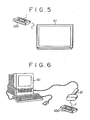
- Fig. 5 is a diagram showing an example in which communication can be established between a cassette 100 and a television receiver 51.
- the television receiver 51 is provided with a reader/writer 21 shown in Fig. 2.
- the reader/writer 21 is installed on the television receiver 51 so that the antenna 22 of the reader/writer 21 is directed to the outside of the television receiver 51.
- communication can be established between the memory card 1 mounted on the cassette 100 and the reader/writer 21 installed on television receiver 51, allowing the reader/writer 21 to read out data stored in the memory card 1.
- the data read out from the memory card 1 is then supplied to the television receiver 51 to be displayed on a screen thereof. Conversely, predetermined data can be transmitted to the memory card 1 to be stored therein.
- Fig. 6 is a diagram showing a state in which a reader/writer 21 shown in Fig. 2 is connected to a personal computer 61, referred to hereafter simply as a PC 61, allowing the PC 61 to read out and to write data from and to a memory card 1 mounted on a cassette 100.
- the reader/writer 21 is controlled by the PC 61 which issues instructions to the PC 61 to read out and to write data from and to the memory card 1.
- Fig. 7 is a diagram showing a state in which a reader/writer 21 shown in Fig. 2 is provided on a remote commander or a display apparatus 71.
- the remote commander or the display apparatus 71 is provided with a display unit 71a which is capable of displaying information such as characters and a graphic, allowing data read out from a memory card 1 to be displayed thereon.
- An operation unit 71b is operated to transmit data to the memory card 1 to be stored therein.
- Fig. 8 is a diagram showing a state in which a reader/writer 21 shown in Fig. 2 is provided on a printer 81.
- the printer 81 is capable of communicating with a memory card 1 mounted on a cassette 100, reading out data stored in the memory card 1 and printing the data on a predetermined piece of paper. The paper can then be stuck to the cassette as an index card.
- an operation unit 81a data can be entered and transmitted to the memory card 1 to be stored therein.
- Fig. 9 is a block diagram showing a typical internal configuration of the VTR 41 shown in Fig. 4.
- the reader/writer 21 has a plurality of antennas 22-1 and 22-2.
- a microcomputer 95 controls the reader/writer 21 through a communication line 32, exchanges data with the reader/writer 21, reads out data stored in a memory card 1 mounted on a cassette 100 and transmits data to the memory card 1 to be stored therein.
- a compartment 93 forms a space for accommodating a cassette 100.
- a switch 94 is used for detecting whether or not a cassette 100 has been inserted into the compartment 93.
- the antenna 22-2 for communicating with a memory card 1 mounted on a cassette 100 existing outside the VTR 41 is designed to provide extremely strong directivity to an electric wave radiated thereby, that is, directivity that does not have an effect on internal components of the VTR 41.
- a metallic plate 92-2 is provided on the back surface of the antenna 22-2 to prevent an electric wave radiated by the antenna 22-2 from being directed to the inside of the VTR 41.
- a metallic plate 92-1 is provided on the back surface of the antenna 22-1 to prevent an electric wave radiated by the antenna 22-1 from being directed to the inside of the VTR 41.
- the antenna 22-1 provided on the compartment 93 allows communication to be established with a memory card 1 mounted on the cassette 100.
- the antenna 22-2 is further provided typically on the front surface of the VTR 41 shown in Fig. 9 in addition to the antenna 22-1.
- the reader/writer 21 is capable of communicating with a memory card 1 mounted on the cassette 100 through the antenna 22-2 with a high degree of reliability.
- the switch 94 is used for forming a judgment as to whether a cassette 100 exists in the inside or the outside of the VTR 41.
- the switch 94 is pushed by the case of the cassette 100, detecting the insertion of the cassette 100 into the compartment 93.
- a signal indicating the insertion of the cassette 100 into the compartment 93 is supplied to the microcomputer 95 from the switch 94.
- the microcomputer 95 is capable of forming a judgment as to whether a cassette 100 exists in the inside or the outside of the VTR 41.
- the microcomputer 95 Informed by the signal from the switch 94 that a cassette 100 has been inserted into the compartment 93, the microcomputer 95 operates the antenna 22-1 to establish communication with the cassette 100 inserted into the compartment 93 through the antenna 22-1.
- the data stored in the memory card 1 is updated in a batch operation when the cassette 100 is ejected from the VTR 41. This is because communication between a reader/writer 21 installed in the VTR 41 and the memory card 1 mounted on the cassette 100 is carried out by using a carrier in the short to intermediate wavelength band.
- the memory card 1 can be provided with an antenna 111 for supplying power thereto besides the antenna 2 for communication as shown in Fig. 10.
- the antenna for communication requires a pass band to a certain degree in order to assure a predetermined transmission speed, making it impossible to increase the Q of the communication antenna where the Q is defined as a ratio of the center frequency of a tuning circuit to the effective band width.
- the level of a carrier received by the communication antenna for delivering power becomes lower as the distance increases, making it no longer possible to assure enough power for the communication.
- an antenna for supplying power can have a Q high enough for fetching a high carrier level, hence, being capable of delivering required power even for a long communication distance. As a result, the communication distance can be lengthened.
- a carrier received by the antenna 111 is supplied to a tuning circuit 112.
- the tuning circuit 112 is designed to give a Q as high as possible so that the power extracted thereby can be increased to a maximum. As a result, the reception level of the carrier can be raised, improving the efficiency of the power conversion.
- Fig. 11 is a diagram showing a typical structure of data stored in the memory unit of the memory card 1, that is, the EEPROM unit 9.
- the storage area of the memory card 1 comprises a card data area, a video-recording-reservation data area, a program - reproduction data area and an event data area.
- the card data area is used for storing intrinsic information of the cassette 100.
- Fig. 12 is a diagram showing a typical data structure of the card data area of the memory card. As shown in the figure, the card data area is used for recording, among other data, the following information:
- the category information indicates the type of the application such as a consumer application, a business application or another application. Depending upon the category information, the entire memory structure and data allocation can be changed. The following is description given on the assumption that data is stored in the memory for category information indicating a consumer application, that is, description of a structure of allocation of memory for a consumer application.
- data representing a halt position of the cassette 100 is stored.
- data representing the time that has lapsed since the start of an operation to reproduce data is stored in terms of hours, minutes, seconds and frames. Accordingly, when a cassette 100 is mounted on the VTR 41 after being taken off once from the VTR 41, the current position of the cassette 100 can be displayed instantaneously. As a result, the operatability of the VTR 41 can be improved.
- the current position will be changed without updating the information on the current position stored in the memory card.
- comparison of the information on the current position stored in the memory card 1 with information on the current position detected by another means indicates a difference between the two, an attempt will be made to store the detected information on the halted position into the memory card 1. In this way, the information on the current position stored in the memory card 1 can be updated with information on the current position representing the actual position.
- the current position of the cassette can be detected by adopting the following method. For example, data is reproduced from the cassette 100 and the current position can be found from the rotational speed of a reel motor. As an alternative, the current position can be recognized by reproducing information on the current position written at specific positions. In particular, in the case of a video apparatus, positional counter information inserted into the intervals of a vertical-synchronization signal can be used.
- the flowchart begins with a step S1 at which the microcomputer 95 issues a command to the reader/writer 21 by way of a communication line 32, requesting the reader/writer 21 to read out information on the current position stored in the card data area of the memory card 1 mounted on the cassette 100.
- the reader/writer 21 reads out information on the current position stored in the card data area of the memory card 1 mounted on the cassette 100 through the antenna 22-1.
- the flow of processing then goes on to a step S2 to form a judgment as to whether or not the information on the current position has all been read out by a microcomputer 27 employed in the reader/writer 21. If the information on the current position has not all been read out, the flow of processing returns to the step S1 to repeat the pieces of processing carried out at the steps S1 and S2 till the information on the current position is all read out. If the information on the current position has all been read out, on the other hand, the flow of processing proceeds to a step S3. At that time, the information on the current position read out from the memory card 1 is supplied to the microcomputer 95 by way of the communication line 32.
- step S3 an operation such as reproduction of data is carried out under the control of the microcomputer 95.
- the microcomputer 95 From the rotational speed of the reel motor, the microcomputer 95 infers the current halted position of the cassette 100.
- the flow of processing then continues to a step S4 at which the inferred value of the current position is compared with the information on the current position stored in the memory card 1 and supplied to the microcomputer 95 by the reader/writer 21.
- the flow of processing goes on to a step S5 to form a judgment as to whether or not the inferred value of the current position agrees with the information on the current position stored in the memory card 1 or whether or not the difference between the two is within a predetermined range of errors. If the inferred value of the current position does not agree with the information on the current position stored in the memory card 1, the actual current position is judged to have been changed in a reproduction operation or the like carried out by another VTR without updating the information on the current position stored in the memory card 1 mounted on the cassette 100. In this case, the flow of processing proceeds to a step S6 at which the information on the current position inferred at the step S3 is written into a predetermined buffer memory.
- step S7 the presently inferred current position is finally regarded as valid data representing the actual current position and the information on the current position stored in the memory card 1 is updated with the inferred value of the present position written in the buffer memory to complete the processing. If the outcome of the judgment formed at the step S5 indicates that the inferred value of the current position agrees with the information on the current position stored in the memory card 1, on the other hand, the information on the current position stored in the memory card 1 is regarded as correct information. In this case, the processing is completed without updating the information on the current position stored in the memory card 1.
- Fig. 14 is a diagram showing a typical data structure of the video-recording-reservation data area shown in Fig. 11.
- the video-recording-reservation data area is used for storing information on a timer-based video-recording reservation.
- the microcomputer 95 employed in the VTR 41 reads in the information on a timer-based video-recording reservation through the reader/writer 21, comparing the information with the present time and the date of today. If the information on a timer-based video-recording reservation is found valid, the microcomputer 95 sets the information in a timer circuit not shown in the figure, putting the VTR 41 in a video-recording reservation state.
- This function is simpler than the ordinary video-recording-reservation function which is executed by the user by operating the VTR 41 or a remote commander. This function is yet convenient for repeatedly recording an event such as a regular daily program.
- the video-recording - reservation data area is used for storing data required for making a timer-based video-recording reservation including:
- the above pieces of information are converted into data with a format for the video-recording-reservation function of the VTR 41.
- Fig. 15 shows a flowchart representing a procedure of processing carried out by the microcomputer 95 to execute the video-recording-reservation function based on information on a video-recording reservation stored in the video-recording reservation data area of a memory card 1 mounted on a cassette 100.
- the flowchart begins with a step S11 at which the microcomputer 95 reads in data stored in the video-recording reservation data area of the memory card 1 mounted on the cassette 100.
- the microcomputer 95 issues a command to the reader/writer 21 through the communication line 32, requesting the reader/writer 21 to read out the information on a timer-based video-recording reservation stored the video-recording-reservation data area of the memory card 1 mounted on the cassette 100.
- the reader/writer 21 reads out the information on a timer-based video-recording reservation, that is, video-recording-reservation data, from the video-recording-reservation data area of the memory card 1 through the antenna 22-1.
- the flow of processing then goes on to a step S12 to form a judgment as to whether or not the video-recording reservation data, that is, program data, has all been read out by a microcomputer 27 employed in the reader/writer 21.
- the flow of processing returns to the step S11 to repeat the pieces of processing carried out at the steps S11 and S12 till the video-recording-reservation data is all read out. If the video-recording-reservation data has all been read out, on the other hand, the flow of processing proceeds to a step S13.
- the video-recording-reservation data read out by the microcomputer 27 is checked to form a judgment as to whether the data is valid or invalid.
- the data is checked, for example, to form a judgment as to whether or not the broadcasting start time of a program reserved for video recording is a time after the present time or, if the broadcasting start time of a program reserved for video recording is a time after the present time, the start time is within 24 hours after the present time.
- step S14 the video-recording reservation data is transformed into video-recording-reservation data with a format that can be processed by the microcomputer 95 employed in the VTR 41.
- step S15 the VTR 41 enters a state to wait for the reserved video recording, terminating the processing. If the outcome of the judgment formed at the step S13 indicates that the video-recording-reservation data is invalid, on the other hand, the processing is terminated.
- a video-recording reservation can be made in accordance with video-recording-reservation data recorded in advance in the video-recording-reservation data area of a memory card 1 mounted on a cassette 100 as described above, in order to record a program broadcasted at a predetermined time every week, for example, the user needs only to set the cassette 100, which has a memory card 1 with the video-recording-reservation data of the program stored therein, in the VTR 41. In this way, the program can be recorded.
- the user is capable of making a video-recording reservation of the program without the need to enter video-recording - reservation data of the program.
- Fig. 16 is a diagram showing a typical data structure of a program-reproduction data area of the memory card 1 shown in Fig. 11.
- the program-reproduction data area is used for recording data for an automatic reproduction.
- An RPT (Repeat Play) field shown in the figure is a two-bit field used for recording data representing a reproduction mode such as a one-time reproduction operation, a two-time reproduction operation and a repeated reproduction operation.
- a TAG (operation bit) field is a six-bit field used for recording data regarding the operation specification of an area in which a program is recorded. Examples of the operation specification are a normal reproduction operation and a slow reproduction operation.
- a POS (Program Relative Position) field is an eight-bit field used for recording relative-position data indicating a reproduction position of the cassette 100 from which a reproduction operation is to be started.
- the microcomputer 95 employed in the VTR 41 reads out data recorded in the program-reproduction data area of the memory card 1 mounted on the cassette 100, using the data for controlling other elements in an automatic reproduction operation.
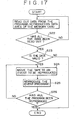
- Fig. 17 shows a flowchart representing the procedure of processing carried out by the microcomputer 95 in an automatic reproduction operation.
- the flowchart begins with a step S21 at which data recorded in the program-reproduction data area of the memory card 1 mounted on the cassette 100 is read out. That is to say, the microcomputer 95 issues a command to the reader/writer 21 by way of the communication line 32, requesting the reader/writer 21 to read out the data recorded in the program-reproduction data area of the memory card 1 mounted on the cassette 100.
- the reader/writer 21 reads out program-reproduction data recorded in the program-reproduction data area of the memory card 1 mounted on the cassette 100 through the antenna 22-1.
- the flow of processing then goes on to a step S22 to form a judgment as to whether or not all the program-reproduction data has been read out from the program-reproduction data area by the microcomputer 27 employed in the reader/writer 21. If all the program-reproduction data has not been read out, the flow of processing returns to the step S21 at which the microcomputer 27 repeats the operation to read out the data till all the program-reproduction data is read out from the program-reproduction data area. If all the program-reproduction data has been read out from the program-reproduction data area, on the other hand, the flow of processing continues to a step S23.
- the program-reproduction data read out by the microcomputer 27 is checked to form a judgment as to whether the program-reproduction data read is valid or invalid, that is, to form a judgment as to whether or not the format and other attributes of the data are correct. If the program-reproduction data read out by the microcomputer 27 is found valid, the flow of processing proceeds to a step S24 at which the head of the VTR 41 is moved to an initial reproduction position specified in the program-reproduction data read out by the microcomputer 27 at the step 21 by feeding the tape of the cassette 100 at a high speed or rewinding it. It should be noted that the head itself is not shown in the figure. The flow of processing then goes on to a step S25 at which recorded data specified in the program-reproduction data is reproduced.
- step S26 the flow of processing proceeds to a step S26 to form a judgment as to whether or not the last piece of the program-reproduction data has been processed. If the last piece of the program-reproduction data has not been processed, the flow of processing returns to the step S24 to repeat the processing starting from the step S24. If the last piece of the program-reproduction data has been processed, on the other hand, the processing is ended.
- a reproduction operation can be carried out in accordance with the procedure.
- Such a reproduction procedure is used typically in editing work.
- similar processing can be carried out even if absolute position data is recorded in the data POS field of the program-reproduction data area.
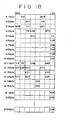
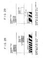
- Fig. 18 is a diagram showing a typical data structure of an event data area of the memory card 1 shown in Fig. 11.
- a RM (Record Mode) field shown in the figure is a two-bit field used for storing information on the recording mode such an image-only recording mode, a sound-only recording mode or an image-and-sound recording mode.
- a MIN field is a six-bit field used for recording the minute portion of a date and a time which is expressed in terms of hours, minutes and seconds. The broadcasting of a recorded program is started on the date and the time.
- a WEEK field is a three-bit field for recording a day of the week of the date.
- An HOUR field is a five-bit field for recording the hour portion of the time.
- a YR field is a seven-bit field comprising three high-order bits and four low-order bit for recording the year portion of the date.
- a DAY field is a five-bit field for storing the day portion of the date.
- a MTH field is a four-bit field for storing the month portion of the date.
- the ID (Station ID) field is used for recording the ID of a broadcasting station.
- a SEL (Input Select) field is used for recording a selected input method.
- CHR (Station ID1-ID5) fields are each used for recording a string of characters of typically the name of a broadcasting station. There are five CHR fields corresponding to station ID1 to station ID5.
- a SR (Recording Speed) field is used for recording a video-recording speed.
- a RP (Record Protect) field is used for recording information as to whether a write operation is inhibited or enabled.
- a (CHN Audio CH No.) field is a two-bit field for recording the number of audio channels.
- An AMD (Audio Mode) field is a four-bit field for recording an audio mode such as a stereo mode or an audio multiplexing mode.
- a VEF (Video Emphasis) field and an AEF (Audio Emphasis) field are each a 1-bit field for recording information on a reproduction method depending on the tape such a reproduction method suitable for a rental cassette tape.
- An N/C (Video System) field is a one-bit field used for recording data indicating a television broadcasting system such as PAL or NTSC.
- a STY (Set Up Data) field is a five-bit field used for recording data indicating a recording system such as a VHS or a SVHS.
- a KY (Key Information) field and a KYO field are each a four-bit field used for recording a lock key for the program.
- the fields represent a two-digit lock key.
- a recorded program may be intended only for certain individuals in which case a minor lock key, that is, a lock key for preventing persons under age from watching the program, is required. In this way, each program can be provided with a lock key (a password) set for a certain individual.
- a TXT (Title Exists) field is a one-bit field for recording data indicating whether or not the title of a program is recorded.
- a BCT (Basic Category) field, a three-bit field, and a CNT (Category Contents) field, a four-bit field, are used for storing the category of a program. For example, data representing a sport category is recorded in the BCT field and data representing a baseball is recorded in the CNT.
- a TCO (Text Code) field is an eight-bit field used for recording data concerning the language of a program such Japanese or English.
- An (Extended Data Bank) EBK field is an eight-bit field used for recording data for specifying an extension data area.
- An extension data area is used for recording a pointer pointing to an area in which information on a recorded program such as images and sound of the program is stored.
- the next two blocks comprising 32 bytes are used for recording information on the title of the program.
- a TDP Total Number of Text-Data Pieces
- the next CHR Charger Code fields of the subsequent bytes following the TDP byte in the two blocks are each an eight-bit field. The CHR fields are used for recording character codes of the title of the program.
- an index to data recorded in the cassette 100 can be displayed on the display unit of the VTR 41 and the television receiver 42.
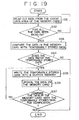
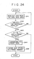
- Fig. 19 shows a flowchart representing a procedure of processing which is carried out by the microcomputer 95 when most recent data is written over event data recorded earlier in the event data area of the memory card 1 mounted on the cassette 100.
- the flowchart begins with a step S31 at which the microcomputer 95 issues a command to the reader/writer 21 by way of the communication line 32, requesting the reader/writer 21 to read out the data recorded in the event data area of the memory card 1 mounted on the cassette 100.
- the reader/writer 21 reads out event data recorded in the event data area of the memory card 1 mounted on the cassette 100 through the antenna 22-1.
- the flow of processing then goes on to a step S32 to form a judgment as to whether or not all the event data has been read out from the event data area by the microcomputer 27 employed in the reader/writer 21. If all the event data has not been read out, the flow of processing returns to the step S31 at which the microcomputer 27 repeats the operation to read out the data till all the event data is read out from the event data area.
- step S33 the event data read out from the memory card 1 at the step S31 as requested by the microcomputer 95 is compared with event data stored temporarily in the microcomputer 95. The flow of processing then proceeds to a step S34 to form a judgment as to whether or not the event data read out at the step S31 as requested by the microcomputer 95 matches the event data stored temporarily in the microcomputer 95.
- step S31 If the event data read out at the step S31 as requested by the microcomputer 95 does not match the event data stored temporarily in the microcomputer 95, the flow of processing continues to a step S35 at which the most recent event data stored in the microcomputer 95 is written into a buffer memory not shown in the figure. Then, the flow of processing goes on to a step S36 at which the most recent data stored in the buffer memory is used for updating the event data stored in the event data area of the memory card 1 corresponding to the most recent event data.
- the flow of processing then proceeds to a step S37 to form a judgment as to whether or not the event data stored in the memory card 1 read out at the step S31 as requested by the microcomputer 95 matches the event data stored temporarily in the microcomputer 95 for a verification purpose.
- event data for programs which are recorded in the cassette 100 after the cassette 100 is mounted on the VTR 41 is stored temporarily in the microcomputer 95. Therefore, when the cassette 100 is taken out from the VTR 41, the event data stored temporarily in the microcomputer 95 is copied to the event data area of the memory card 1 mounted on the cassette 100. If a new program is recorded in the cassette 100 over a program already existing therein, for example, the event data for the new program is written over the temporarily stored event data for the already existing program in the VTR 41. When the cassette 100 is taken out from the VTR 41, the most recent event data for the new program recorded in the cassette 100 is therefore recorded on the memory card 1 mounted on the cassette 100.
- Event data stored in the memory card 1 includes information on the current position indicating a location in the cassette 100 at which a program associated with the event data is recorded.
- the microcomputer 95 also includes information on the position in the event data for the new program stored temporarily therein.
- the flow of processing returns to the step S35 to repeat pieces of processing at the step S35 and the subsequent steps. If the outcome of the judgment formed at the step S37 indicates that the event stored in the memory card 1 matches the event data stored temporarily in the microcomputer 95, on the other hand, the processing is completed. In addition, if the outcome of the judgment formed at the step S34 indicates that the event stored in the memory card 1 matches the event data stored temporarily in the microcomputer 95, on the other hand, the processing is completed.
- the title of a program can be obtained with ease by using an EPG (Electronic Program Guide) of broadcasted data inserted into the interval of the vertical-synchronization signal. If information on the title of a program can not be obtained, the title of a program included in event data recorded in the event data area of the memory card 1 can be edited by using external accessory equipment provided with a reader/writer.
- EPG Electronic Program Guide
- information on a program such as the title of the program is inserted into the interval of the vertical-synchronization signal in synchronization with each program of the television broadcasting signal.
- Such information can be inserted regularly or at proper times such as the start or the end of a program.
- the title of a program can be supplied to the user.
- the user is capable of recording the title of a program in the memory card 1 mounted on the cassette 100, when necessary, by extracting the title.
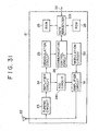
- Fig. 20 is a block diagram showing a typical configuration of an embodiment implementing an information transmitting apparatus 111 provided by the present invention.
- a television-broadcast-signal outputting circuit 112 employed in the information transmitting apparatus 111 receives an audio signal of a program from a video camera or a VTR and a video signal from the video camera or the VTR by way of a multiplexing circuit 114, converting the signals into an output television-broadcast signal.
- a program-title generating circuit 113 generates a signal representing the title of a program, outputting the signal to the multiplexing circuit 114. The title of the program will be conveyed by the television-broadcast signal generated by the television-broadcast-signal outputting circuit 112.
- the multiplexing circuit 114 inserts the signal representing the title of a program generated by the program-title generating circuit 113 into the interval of the vertical-synchronization signal of the video signal input by the information transmitting apparatus 111, multiplexing the signal representing the title of a program with the video signal and outputting the multiplexed signal to the television-broadcast-signal outputting circuit 112.
- a transmitting circuit 115 transmits the television-broadcast signal supplied thereto by the television-broadcast-signal outputting circuit 112.
- the television-broadcast signal output by the television-broadcast-signal outputting circuit 112 includes a multiplexed signal comprising the video signal and the signal representing the title of a program in addition to the audio signal.
- video and audio signals of a program from a video camera or a VTR are supplied to the information transmitting apparatus 111.
- the video signal received by the information transmitting apparatus 111 is supplied to the multiplexing circuit 114 before being converted into a television-broadcast signal by the television-broadcast-signal outputting circuit 112.
- the program-title generating circuit 113 generates a signal representing the title of the program from the information on the title of the program, supplying the signal to the multiplexing circuit 114.
- the multiplexing circuit 114 inserts the signal representing the title of a program generated by the program-title generating circuit 113 into the interval of the vertical-synchronization signal of the video signal input by the information transmitting apparatus 111, superposing the signal representing the title of the program on the video signal.
- the video signal superposed with the title of the program is then supplied to the transmitting circuit 115 by way of the television-broadcast - signal outputting circuit 112.
- the television-broadcast signal output by the television-broadcast-signal outputting circuit 112 is used in the transmitting circuit 115 for modulating the frequency of a carrier prior to transmission.
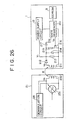
- Fig. 21 is a diagram showing a typical configuration of a VTR 121 wherein a television-broadcast signal with information such as the title of a program superposed in the interval of the vertical-synchronization signal thereof is supplied thereto from the information transmitting apparatus 111 shown in Fig. 20.
- the VTR 121 further includes a television-broadcast-signal receiving circuit 122 and a program-title extracting circuit 123 in addition of components composing the VTR 41 shown in Fig. 9.
- the television-broadcast-signal receiving circuit 122 receives a television-broadcast signal transmitted by the transmitting circuit 115 employed in the information transmitting apparatus 111.
- the television-broadcast signal received by the television-broadcast-signal receiving circuit 122 is then forwarded to a program-title extracting circuit 123 described below and a recording/reproduction circuit which is not shown in the figure.
- the program-title extracting circuit 123 extracts a signal representing the title of a program superposed in the interval of the vertical-synchronization signal of the television-broadcast signal supplied thereto from the television-broadcast-signal receiving circuit 122, supplying the extracted signal to the microcomputer 95.
- the television-broadcast signal transmitted by the transmitting circuit 115 employed in the information transmitting apparatus 111 received by the television-broadcast-signal receiving circuit 122 is forwarded to the program-title extracting circuit 123 and the recording/reproduction circuit.
- the program-title extracting circuit 123 then extracts a signal representing the title of a program superposed in the interval of the vertical-synchronization signal of the television-broadcast signal supplied thereto from the television-broadcast-signal receiving circuit 122, supplying data such as character codes of the title of the program to the microcomputer 95.
- the microcomputer 95 supplies the data representing the title of the program supplied thereto to the reader/writer 21 by way of the communication line 21.
- the reader/writer 21 then writes the data representing the title of the program supplied thereto by the microcomputer 95 into the memory card 1 by way of the antenna 22-1 or 22-2.
- the title of a program which is obtained by the user by reading out a program guide from a publication such as a newspaper or a magazine can be recorded in a memory card 1 mounted on a cassette 100 by way of the reader/writer 21 connected to the PC 61.
- the title of a program can be acquired from the data base and recorded in the memory card 1 by way of the reader/writer 21.
- the title of a program can be obtained from a program guide described in an electronic publication such as a CD-ROM and recorded in the memory card 1.
- the title of a program supplied through means such as an XDS (Extended Data Service), a PDS (Program Delivery Service) or a character multiplexing broadcast system can be acquired and recorded in the memory card 1.
- the satellite-broadcasting receiver is connected to an external input terminal of the VTR 1 through which a baseband signal to be recorded is supplied.
- the VTR 41 since the VTR 41 is not capable of obtaining desired information such as the title of a program to be recorded, the required data is re-inserted into the interval of the vertical-synchronization signal of a signal received by the satellite-broadcasting receiver and transmitted to the VTR 41 by way of a bus connecting the VTR 41 and the satellite-broadcasting receiver.
- a program category is additional information for identifying the category and other data of a recorded program.
- a program category can be used for searching a recording medium such as a cassette tape for a desired program.
- An area appended as an extension data area is used for storing information pertaining to a recorded program such as video and audio data. By displaying images (video data) and outputting sound (audio data) stored in such an area in addition to characters, the display of contents recorded in a cassette can be made easy to understand.
- applications of the memory card 1 also include business and preset-work applications.
- information stored in the memory card includes the title of a recorded program, the number of operations reproducing the program, information on a borrower of the cassette such as a member ID, a borrowing day and a borrowing period, not to mention other necessary information such as a static image, sound and character data.
- Fig. 22 is a diagram showing a typical data structure of information for a business application stored in the memory card 1.
- a CAT (Category) field shown in the figure is a four-bit field used for recording information such as the title of a recorded program.
- An EVT (Number of Events) field is a four-bit field used for recording the number of events (programs).
- An MB1 field is an eight-bit field used for recording the storage capacity of the memory.
- a PDC (Professional Data Category) field is an eight-bit field used for storing a category of information for a business application.
- a LEN (Professional Data Length) field is used for storing the data length of the information for a business application.
- a DTA (Professional Data) field is used for recording the information for a business application.
- the information for a business application includes the title of a recorded program, the number of operations reproducing the program and information on borrowers of the cassette such as a member ID, a borrowing day and a borrowing period.
- the information for a business application includes other necessary information such as a static image, sound and character data.
- a memory card 1 of a business application By using a memory card 1 of a business application as a member card, data to be recorded can be shared by the reader/writer 21 and the memory card 1.
- information on a member stored in a member card can be supplied to the PC 61 by way of the reader/writer 21 and, on the other hand, information such as a borrowing date and a borrowing period entered to the PC 61 can be stored in the member card.
- the information on a member stored in a member card can be transferred to another memory card 1 of any cassette 100 with ease. As a result, control of customers and commodities can be executed with a high degree of efficiency.
- the memory card 1 can be used for automatic installation of preset guide information.
- channel numbers are set in accordance with an area in which the target apparatus such as the VTR is installed.
- the user carries out an operation to store such channel numbers in a preset memory.
- the preset work to store such channel numbers in a preset memory can be done automatically.
- information recorded in a memory card 1 for automatic installation of preset guide information typically includes data required in initial setting of a recording/reproduction apparatus such as a VTR, a table containing tuner preset data, data for presetting a G-code area, information on a manufacturer of a CATV (cable television) cable box and other information on the recording/reproduction apparatus.
- a recording/reproduction apparatus such as a VTR
- a table containing tuner preset data data for presetting a G-code area
- information on a manufacturer of a CATV (cable television) cable box information on the recording/reproduction apparatus.
- Fig. 23 is a diagram showing a typical data structure of preset information stored in the memory card 1.
- a CAT (Category) field shown in the figure is a four-bit field used for recording a category which indicates that the information stored in the memory card is preset information.
- An EVT (Number of Events) field is a four-bit field used for recording the number of pieces of stored information.
- An MB1 field is an eight-bit field used for recording the storage capacity of the memory.
- a PDC (Preset Data Category) field is used for storing a category of preset data.
- a LEN (Preset Data Length) field is used for storing the data length of the preset data.
- a DTA (Preset Data) field is used for recording the preset data.
- Fig. 24 shows a flowchart representing a procedure of processing carried out by the microcomputer 95 to update information of a preset memory of the VTR 41 in accordance with preset information recorded in the memory card 1. It should be noted that the preset memory is shown in none of the figures.
- the flowchart begins with a step S41 at which the microcomputer 95 issues a command to the reader/writer 21 by way of the communication line 32, requesting the reader/writer 21 to read out the preset information recorded in the card data area of the memory card 1 mounted on the cassette 100.
- the reader/writer 21 reads out preset information recorded in the card data area of the memory card 1 mounted on the cassette 100 through the antenna 22-1.
- the flow of processing then goes on to a step S42 to form a judgment as to whether or not all the preset information has been read out from the card data area by the microcomputer 27 employed in the reader/writer 21. If all the preset information has not been read out, the flow of processing returns to the step S41 at which the microcomputer 27 repeats the operation to read out the information till all the preset information is read out from the card data area. If all the preset information has been read out from the card data area, on the other hand, the flow of processing continues to a step S43.
- the preset information read out at the step S41 as requested by the microcomputer 95 is checked to form a judgment as to whether or not the preset information read out from the card data area is information corresponding to the preset category.
- the judgment is based on information recorded in the CAT field of the information read out from the card data area. If the information recorded in the CAT field indicates that the preset information read out from the card data area is information corresponding to the preset category, the flow of processing goes on to a step S44 at which the microcomputer 95 converts the format of the preset information into a format of data to be processed by the microcomputer 95.
- step S45 the contents of the preset memory of the VTR 41 are updated with preset data resulting from the conversion carried out at the step 44.
- the preset memory itself is shown in none of the figures. After that, the processing is completed. If the outcome of the judgment formed at the step S43 indicates that the preset information read out from the card data area is not information corresponding to the preset category, on the other hand, the processing is completed without updating the contents of the preset memory of the VTR 41.
- the user is capable of carrying out a preset operation by merely setting a cassette 100 having a memory card 1 for storing preset data mounted thereon on the VTR 41 without the need to do cumbersome work.
- the reader/writer 21 is capable of reading out the preset data stored in the memory card 1 through the antenna 22-2 without the need for the user to mount the memory card 1 on the cassette 100.
- various kinds of information on data recorded in a cassette or disc can be stored in the memory card 1 and the information can be used for simplifying operations to display the data, to reproduce a program, to make a timer-based video-recording reservation and to search a tape for a start position, to mention a few.
- the present invention can be applied to the ordinary cassette tape or disc by merely mounting the memory card on the ordinary cassette tape or disc.
- audio and video recording media such as cassette tapes and floppy discs can be manufactured without changing their specifications and recording formats:
- the cassette tapes and discs can be controlled and organized with ease.
- an EEPROM unit 9 is used in an embodiment. It should be noted, however, that other storage devices can also be employed as well. For example, a memory device consuming only a small amount of power such as the FeRAM (a ferroelectric RAM) can also be used. In this case, the communication distance can also be increased as well.
- FeRAM ferroelectric RAM
- information stored in the memory card 1 is updated when the cassette is taken out from an apparatus such as a VTR. It should be noted, however, that the information can also be updated periodically or at any time new data for updating the information is generated. As an alternative, the information can also be updated with predetermined timing.
- a ROM unit for storing a program is connected to a microcomputer. It is worth noting, however, that the ROM can also be embedded in the microcomputer.
- the data structures of the memory card in the embodiments described above are typical. That is to say, the present invention is not limited to the data structures described above.
- the memory card 1 is mounted on a cassette in most cases. It is worth noting, however, that the memory card 1 can be mounted on other recording media such as a FD (floppydisc), a MD (minidisc, a trademark), a tape streamer, an MO (magneto-optics) disc used as a magneto-optic recording medium and optical recording media like a DVD (Digital Versatile Disc), a CD-ROM (Compact Disc Read-Only Memory), a CD (Compact Disc) and a CDV (Compact Disc Video).
- FD floppydisc
- MD minidisc, a trademark
- MO magnetic-optics
- DVD Digital Versatile Disc
- CD-ROM Compact Disc Read-Only Memory
- CD Compact Disc
- CDV Compact Disc Video
- Fig. 25 is a block diagram showing another typical configuration of a memory card 1. As shown in the figure, this configuration is obtained from the configuration shown in Fig. 1 by replacing the microcomputer 7 shown in Fig. 1 with a gate sequencer 201. The rest is the same as the configuration shown in Fig. 1. That is to say, by replacing the microcomputer 7 in the configuration shown in Fig. 1 with a gate sequencer 201 comprising logic gates, the same functions as those of the microcomputer 7 can be implemented by the gate sequencer 201.
- Fig. 26 is a block diagram showing another typical configuration of the meory card 1 and the reader/writer 21. As shown in the figure, in this configuration, the antenna 2 employed in the memory card 1 is implemented by a coil 211 whereas the antenna 22 employed in the reader/writer 21 is implemented by a coil 232. Mutual electromagnetic inductive coupling is established between the coils 211 and 232.
- a diode 212 is connected in series to the coil 211 at one end thereof.
- the other end of the diode 212 is connected to a resistor 213 and a capacitor 214 which form a resonant circuit with the coil 211.
- the resonant circuit functions as the tuning circuit 3 shown in Fig. 1.
- a series circuit comprising a resistor 215 and a FET 216 is connected to the capacitor 214 in parallel.
- the gate of the FET 216 is driven by the gate sequencer 201.
- the other end of the diode 212 is also connected to the gate sequencer 201 through a capacitor 217 and to the power-supply circuit 12.
- a resonant circuit 231 and the demodulation circuit 25 are connected in parallel to the coil 232.
- a resonant circuit for data transmission is not provided in the memory card 1.
- Data is transmitted by changing the impedance of the FET 216 by means of the gate sequencer 201 in accordance with the data being transmitted.
- an impedance of the right side of the coil 211 seen from the coil 211 in the configuration shown in Fig. 26 changes.
- the impedance of coil 232 employed in the reader/writer 21 which is inductively coupled with the coil 211 also changes as well.
- the demodulation circuit 25 detects changes in current flowing through the coil 232 and changes in voltage appearing between the terminals of the coil 232, demodulating a signal received from the card reader 1.
- the oscillation frequency of the resonant circuit 231 is varied in accordance with the data being transmitted.
- the changes in frequency are propagated from the coil 232 of the reader/writer 21 to the coil 211 employed in the memory card 1 through the mutual inductive coupling.
- the signal transmitted by the reader/writer 21 is supplied to the gate sequencer 201 by way of the capacitor 217. In this way, the signal can be received by the gate sequencer 201.
- Fig. 27 shows a flowchart used for explaining processing carried out by the reader/writer 21 to exchange data with the memory card 1 shown in Fig. 26 through the mutual inductive coupling.
- the processing is carried out typically by a gate sequencer 201 employed in the rea der/writer 21.
- the gate sequencer 201 is the same as that employed in the memory card 1 shown in Fig. 25. It should be noted that the gate sequencer 201 employed in the reader/writer 21 is not shown in Fig. 26.
- the flowchart begins with a step S61 at which the gate sequencer 201 (employed in the reader/writer 21) controls the resonant circuit 231 which serves as the modulation circuit 10 in accordance with data being transmitted.
- a carrier is modulated thereby by using the data being transmitted and output from the coil 232.
- the flow of processing then goes on to a step S62 at which the gate sequencer 201 forms a judgment as to whether or not data has been received from the meory card 1. It should be noted that the judgment can be formed by finding out whether or not the level of the carrier has changed. If no data has been received from the memory card 1, the flow of processing proceeds to a step S63 to form a judgment as to whether or not a prefetermined period of time t0 of typically 250 ⁇ s which is set in advance has lapsed since completion of the transmission of the data. If the predetermined period of time t0 has not lapsed, the flow of processing returns to the step S62 at which the gate sequencer 201 agains forms a judgment as to whether or not data has been received from the meory card 1. Thereafter, the pieces of processing of the steps S62 and S63 are carried out repeatedly.
- step S62 If the outcome of the judgment formed at the step S62 indicates that data has been received from the memory card 1 after a period of time t has lapsed since the completion of the transmission of the data where t ⁇ t0 as shown in Fig. 28, the flow of processing continues to a step S64 at which the gate sequencer 201 sets a transmission period at a period of time t2. The flow of processing then goes on to a step S65 to enter a wait state waiting for the period of time t2 to lapse since the start of the transmission of the data. As the period of time t2 lapses since the start of the transmission of the data, the flow of processing returns to the step S61 to again carry out the processing to transmit data.
- step S63 If the outcome of the judgment formed at the step S63 indicates that the predetermined period of time t0 has lapsed since the completion of the transmission of the data without being able to receive any data from the card reader 1 as shown in Fig. 29, on the other hand, the flow of processing proceeds to a step 66 at which the gate sequencer 201 controls the resonant circuit 231 to end the operation to output the carrier. As a result, a waste of power by unnecessary consumption can be prevented.
- the flow of processing goes on to a step S67 at which the gate sequencer 201 sets the transmission period at a period of time t1 which is longer than the period of time t2 set at the step S64. Subsequently, the flow of processing then goes on to a step S68 to enter a wait state waiting for the period of time t1 to lapse since the start of the transmission of the data. As the period of time t1 lapses since the start of the transmission of the data, the flow of processing returns to the step S61 to again carry out the processing to transmit data.
- the period of time t1 is 10 ms and the period of time t2 is 5 ms.
- the reader/writer 21 is provided with an AGC circuit 241 as shown in Fig. 31, a block diagram showing another typical configuration of the reader/writer 21.
- the gain of the amplifier circuit 31 on the transmission side is controlled in accordance with the level of a signal received by the antenna 22 for compensating the data being transmitted for a decrease in level of the carrier.
- the AGC circuit 241 functions only during an operation to transmit data. During an operation to receive data, the voltage controlled in an operation to transmit data is held as it is.
- Fig. 32 is a diagram showing an application of mounting a memory card 1 on a CD-ROM 252.
- data recorded in a CD-ROM can not be updated.
- a CD-ROM is used in car navigation for recording map data. Map data recorded in the CD-ROM becomes obsolete as new roads and new buildings are completed after the map data has been recorded in the CD-ROM.
- a memory card 1 can be used for storing map information for newly completed roads and buildings and distributed to users.
- the memory card 1 can then be mounted on or attached to a CD-ROM 252 which contains map data before changes in map.
- a drive 253 of a navigation system or the PC 61 shown in Fig. 6 carries out processing represented by a flowchart shown in Fig. 33.
- the flowchart begins with a step S81 at which data recorded on the CD-ROM 252 is read out by using a pickup 251 shown in Fig. 32.
- the flow of processing then goes on to a step S82 to form a judgment as to whether or not the processing to read out data from the CD-ROM 252 has been completed. If the outcome of the judgment indicates that the processing to read out data from the CD-ROM 252 has not been completed, the flow retirns to the step S81 to carry out the pieces of processing of the steps S81 and S82 repeatedly till the processing to read out data from the CD-ROM 252 is completed.
- step S82 As the outcome of the judgment formed at the step S82 indicates that the processing to reproduce data from the CD-ROM 252 has been completed, the flow proceeds to a step S83 to form a judgment as to whether or not a memory card 1 is attached to the CD-ROM 252. If the outcome of the judgment indicates that a memory card 1 is attached to the CD-ROM 252, the flow of processing continues to a step S84 at which the reader/writer 21 reads out information stored in the memory card 1. Then, the flow of processing goes on to a step S85 at which the drive 253 uses the information read out from the memory card 1 at the step S84 for updating the data reproduced from the CD-ROM 252 at the step S81or merely adds the information to the data.
- the obsolete map data is updated with the information read out from the memory card 1 or information on newly completed roads and buildings read out from the memory card 1 can be added to the data reproduced from the CD-ROM 252. As a result, the user can use most recent map data.
- step S83 If the outcome of the judgment formed at the step S83 indicates that a memory card 1 is not attached to the CD-ROM 252, on the other hand, the steps S84 and S85 are skipped.
- the present invention is applied to a CD-ROM used as a recording medium.
- the scope of the present invention also includes a memory card added to a ROM for storing a computer program.
- the memory card is used for storing program modifications resulting from a version-up of the program.
- information stored in a memory card 1 can be code of a computer program or an executable script.
- a switching means is used for selecting one of the information transmitting/receiving means;
- a reading means is used for reading out information stored in the storage apparatus through one of the information transmitting/receiving means selected by the switching means; and
- an information supplying means is used for supplying update information for updating the information stored in the storage apparatus through one of the information transmitting/receiving means selected by the switching means.
- information on data is transmitted and received to and from a storage apparatus mounted on a recording-medium assembly for recording the data; information is read out from the storage apparatus; and the information read out from the storage apparatus is output.
- the information on the data recorded in the recording-medium assembly can be acquired with ease.
- a storage means is used for storing information; a power inputting means is used for inputting power supplied by an external apparatus; an information supplying means is used for providing the information stored in the storage means to the external apparatus; and an information updating means is used for updating the information stored in the storage means with information received from the external apparatus.
- the storage means can be of a noncontact type and is capable of storing information supplied by an external source as well as capable of updating information stored therein.
- information read out from a storage apparatus is used for updating data reproduced from a recording-medium assembly or added to the data.
- the user can use the most recent data resulting from the updating of the data reproduced from the recording-medium assembly with the information read out from the storage apparatus or resulting from the addition of the information to the data.
- an information superposing means is used for superposing information to be stored in a storage apparatus on data to be recorded into a recording-medium assembly; and an information transmitting means is used for transmitting the data with the information superposed thereon by the information superposing means.
- information on data to be stored in the storage apparatus mounted on the recording-medium assembly for recording the data can be transmitted by superposing the information on the data and, on the receiving side, the information on the data can be acquired with a high degree of reliability and then stored in the storage apparatus.
Applications Claiming Priority (5)
| Application Number | Priority Date | Filing Date | Title |
|---|---|---|---|
| JP34486396 | 1996-12-25 | ||
| JP34486396 | 1996-12-25 | ||
| JP5009897 | 1997-03-05 | ||
| JP5009897 | 1997-03-05 | ||
| EP97310413A EP0851421A3 (de) | 1996-12-25 | 1997-12-22 | Aufzeichnungs-Wiedergabegerät und -Verfahren, Eingangs-Ausgangsgerät und -Verfahren, Speichergerät, Übertragungseinrichtung sowie Informationsverarbeitungsgerät und -Verfahren |
Related Parent Applications (2)
| Application Number | Title | Priority Date | Filing Date |
|---|---|---|---|
| EP97310413.6 Division | 1997-12-22 | ||
| EP97310413A Division EP0851421A3 (de) | 1996-12-25 | 1997-12-22 | Aufzeichnungs-Wiedergabegerät und -Verfahren, Eingangs-Ausgangsgerät und -Verfahren, Speichergerät, Übertragungseinrichtung sowie Informationsverarbeitungsgerät und -Verfahren |
Publications (2)
| Publication Number | Publication Date |
|---|---|
| EP1406263A2 true EP1406263A2 (de) | 2004-04-07 |
| EP1406263A3 EP1406263A3 (de) | 2006-11-02 |
Family
ID=26390535
Family Applications (4)
| Application Number | Title | Priority Date | Filing Date |
|---|---|---|---|
| EP03078476A Withdrawn EP1406263A3 (de) | 1996-12-25 | 1997-12-22 | Aufzeichnungs-/Wiedergabegerät und -verfahren, Eingangs-/Ausgangsgerät und -verfahren, Speichergerät, Übertragungsvorrichtung sowie Informationsverarbeitungsgerät und -verfahren |
| EP03078474A Withdrawn EP1396860A3 (de) | 1996-12-25 | 1997-12-22 | Aufzeichnungs-/Wiedergabegerät und -Verfahren, Eingangs/Ausgangsgerät und -Verfahren, Speichergerät, Übertragungseinrichtung sowie Informationsverarbeitungsgerät und -Verfahren |
| EP03078475A Withdrawn EP1403872A3 (de) | 1996-12-25 | 1997-12-22 | Aufzeichnungs/Wiedergabegerät und -Verfahren, Eingangs/Ausgangsgerät und -Verfahren, Speichergerät, Übertragungseinrichtung sowie Informationsverarbeitungsgerät und -Verfahren |
| EP97310413A Withdrawn EP0851421A3 (de) | 1996-12-25 | 1997-12-22 | Aufzeichnungs-Wiedergabegerät und -Verfahren, Eingangs-Ausgangsgerät und -Verfahren, Speichergerät, Übertragungseinrichtung sowie Informationsverarbeitungsgerät und -Verfahren |
Family Applications After (3)
| Application Number | Title | Priority Date | Filing Date |
|---|---|---|---|
| EP03078474A Withdrawn EP1396860A3 (de) | 1996-12-25 | 1997-12-22 | Aufzeichnungs-/Wiedergabegerät und -Verfahren, Eingangs/Ausgangsgerät und -Verfahren, Speichergerät, Übertragungseinrichtung sowie Informationsverarbeitungsgerät und -Verfahren |
| EP03078475A Withdrawn EP1403872A3 (de) | 1996-12-25 | 1997-12-22 | Aufzeichnungs/Wiedergabegerät und -Verfahren, Eingangs/Ausgangsgerät und -Verfahren, Speichergerät, Übertragungseinrichtung sowie Informationsverarbeitungsgerät und -Verfahren |
| EP97310413A Withdrawn EP0851421A3 (de) | 1996-12-25 | 1997-12-22 | Aufzeichnungs-Wiedergabegerät und -Verfahren, Eingangs-Ausgangsgerät und -Verfahren, Speichergerät, Übertragungseinrichtung sowie Informationsverarbeitungsgerät und -Verfahren |
Country Status (5)
| Country | Link |
|---|---|
| US (2) | US6556768B1 (de) |
| EP (4) | EP1406263A3 (de) |
| AU (1) | AU726982B2 (de) |
| CA (1) | CA2225323C (de) |
| MY (1) | MY123802A (de) |
Families Citing this family (31)
| Publication number | Priority date | Publication date | Assignee | Title |
|---|---|---|---|---|
| EP0580434B1 (de) * | 1992-07-24 | 1999-03-03 | Sony Corporation | Aufzeichnungsmediumkassette |
| US6922520B1 (en) * | 1992-07-24 | 2005-07-26 | Sony Corporation | Recording medium cartridge with memory circuit employing a hierarchical data structure |
| JPH11203832A (ja) * | 1998-01-06 | 1999-07-30 | Sony Corp | 記録可能時間判別方法および記録媒体処理装置 |
| JP2000048129A (ja) * | 1998-07-27 | 2000-02-18 | Sony Corp | 情報処理装置および方法、並びに提供媒体 |
| JP4694660B2 (ja) | 1998-08-04 | 2011-06-08 | ソニー株式会社 | 記録媒体制御方法、記録媒体対応装置 |
| US6172833B1 (en) * | 1998-08-05 | 2001-01-09 | International Business Machines Corporation | Retrieval of serpentine pattern data using a memory device of a tape cartridge |
| IL127569A0 (en) * | 1998-09-16 | 1999-10-28 | Comsense Technologies Ltd | Interactive toys |
| US6607136B1 (en) | 1998-09-16 | 2003-08-19 | Beepcard Inc. | Physical presence digital authentication system |
| JP2000113640A (ja) * | 1998-09-30 | 2000-04-21 | Sony Corp | テープドライブ装置、記録媒体 |
| EP1116155A2 (de) * | 1998-10-02 | 2001-07-18 | Comsense Technologies Ltd. | Karte zur interaktion mit einem computer |
| JP2000173128A (ja) | 1998-12-02 | 2000-06-23 | Sony Corp | テープドライブ装置、記録媒体 |
| AU2047100A (en) * | 1998-12-07 | 2000-06-26 | Index Systems, Inc. | System and method for generating video taping reminders |
| US6792197B1 (en) | 1998-12-07 | 2004-09-14 | Index Systems, Inc. | System and method for generating video taping reminders |
| JP2000285634A (ja) | 1999-03-31 | 2000-10-13 | Matsushita Electric Ind Co Ltd | テープカセット及び記録再生装置及びテープ管理方法 |
| US8019609B2 (en) | 1999-10-04 | 2011-09-13 | Dialware Inc. | Sonic/ultrasonic authentication method |
| US7280970B2 (en) * | 1999-10-04 | 2007-10-09 | Beepcard Ltd. | Sonic/ultrasonic authentication device |
| JP4228522B2 (ja) | 2000-06-30 | 2009-02-25 | ソニー株式会社 | 情報記録装置及び方法 |
| JP4273636B2 (ja) * | 2000-06-30 | 2009-06-03 | ソニー株式会社 | 情報記録装置及び方法、情報記録システム |
| JP2002064782A (ja) * | 2000-08-22 | 2002-02-28 | Sharp Corp | Tv番組の録画、再生方法及びそれらに用いられる装置 |
| US20020118947A1 (en) * | 2000-12-27 | 2002-08-29 | Kuo-Long Shih | Digital video and audio storing and playing device |
| ITMO20010019A1 (it) * | 2001-02-08 | 2002-08-08 | Marcello Lolli | Sistema per l'identificazione e l'autenticazione di un supporto di registrazione dati |
| US9219708B2 (en) | 2001-03-22 | 2015-12-22 | DialwareInc. | Method and system for remotely authenticating identification devices |
| US7075874B2 (en) * | 2001-07-17 | 2006-07-11 | Hewlett-Packard Development Company, L.P. | Data storage device monitoring system, method and removable data carrier use with data storage systems |
| JP2003256789A (ja) * | 2002-02-26 | 2003-09-12 | Sony Corp | メモリ装置及びメモリ収納装置 |
| JP2003347951A (ja) * | 2002-05-29 | 2003-12-05 | Pioneer Electronic Corp | 受信装置、その方法、そのプログラム、そのプログラムを記録した記録媒体、および、通信システム |
| KR100546679B1 (ko) * | 2003-01-07 | 2006-01-26 | 엘지전자 주식회사 | 개인용 비디오 녹화 시스템 및 녹화 방법 |
| JP3841413B2 (ja) * | 2003-02-19 | 2006-11-01 | 任天堂株式会社 | ゲームシステム、ゲーム装置及びゲームプログラム |
| JP2005260672A (ja) * | 2004-03-12 | 2005-09-22 | Toshiba Corp | 携帯端末装置 |
| DE102004049016B3 (de) * | 2004-10-05 | 2005-08-11 | Brinkhus, Hartmut B., Dr. | Schaltungsanordung zur galvanisch getrennten Übertragung eines elektrischen Signals mit einem Optokoppler |
| WO2008042039A1 (en) * | 2006-09-29 | 2008-04-10 | Sandisk Corporation | Video content recording apparatus with electronic program guide functionality and method of use therewith |
| EP2413059A1 (de) * | 2009-03-23 | 2012-02-01 | Panasonic Corporation | Energieversorgungssystem |
Citations (5)
| Publication number | Priority date | Publication date | Assignee | Title |
|---|---|---|---|---|
| WO1989010615A1 (en) * | 1988-04-19 | 1989-11-02 | British Broadcasting Corporation | Cassette for sequential access recording medium and apparatus for use therewith |
| WO1993000680A1 (de) * | 1991-06-21 | 1993-01-07 | Siemens Nixdorf Informationssysteme Ag | Vorrichtung zum verfügbarmachen von den inhalt des massenspeichers eines maschinenlesbaren datenträgers beschreibenden und/oder ergänzenden daten |
| EP0583904A2 (de) * | 1992-08-14 | 1994-02-23 | Sony Corporation | Aufzeichnungsträgerkassette, Anzeigegerät und Aufzeichnungs-Wiedergabegerät |
| US5455409A (en) * | 1993-08-16 | 1995-10-03 | Texas Digital Systems, Inc. | Apparatus and method for monitoring a plurality of coded articles and for identifying the location of selected articles |
| EP0760511A1 (de) * | 1995-09-01 | 1997-03-05 | Staar Societe Anonyme | Vorrichtung zum Abfragen von Information im Kassettenspeicher |
Family Cites Families (34)
| Publication number | Priority date | Publication date | Assignee | Title |
|---|---|---|---|---|
| JPS5441762A (en) * | 1977-09-09 | 1979-04-03 | Nissan Motor | Revolving pointer type meter |
| US4224644A (en) * | 1978-02-08 | 1980-09-23 | Videodetics Corporation | Method and apparatus for controlling a tape player/recorder for retrieving and playing prerecorded information |
| DE3040137A1 (de) * | 1980-10-24 | 1982-05-13 | Standard Elektrik Lorenz Ag, 7000 Stuttgart | Punktfoermige einrichtung zur uebertragung von information zwischen einer trasse und auf dieser gefuehrten fahrzeugen |
| JPH0750921B2 (ja) * | 1985-12-18 | 1995-05-31 | ソニー株式会社 | 編集制御装置 |
| JPH01236737A (ja) * | 1988-03-16 | 1989-09-21 | Seiko Instr & Electron Ltd | データ収集システム |
| JPH04501184A (ja) * | 1988-08-12 | 1992-02-27 | モー,ゴードン | リカバリー記録システム、特に商用ラジオ/テレビ放送のリカバリー記録システム |
| US5070500A (en) * | 1988-08-30 | 1991-12-03 | Tokyo Keiki Company Ltd. | Memory package system utilizing inductive coupling between memory module and read/write unit |
| US4982324A (en) * | 1988-12-19 | 1991-01-01 | International Business Machines Corporation | Method of and system for using device drivers to couple the communication and data storage of remote computer systems |
| JPH02249319A (ja) * | 1989-03-22 | 1990-10-05 | Tokyo Keiki Co Ltd | データ通信方式 |
| JPH0755593B2 (ja) * | 1989-05-18 | 1995-06-14 | 三菱電機株式会社 | 非接触icカード |
| US5450960A (en) * | 1989-09-01 | 1995-09-19 | Fuji Photo Film Co., Ltd. | Cassette containing case with an index card |
| FR2662320B1 (fr) * | 1990-05-18 | 1994-05-13 | Cemagref | Dispositif de liaison sans contact pour relier des troncons de bus serie. |
| US5150099A (en) * | 1990-07-19 | 1992-09-22 | Lienau Richard M | Home security system and methodology for implementing the same |
| US5822145A (en) * | 1991-05-07 | 1998-10-13 | Canon Kabushiki Kaisha | Information recording and/or reproducing apparatus using an information recording device having two kinds of recording media |
| US5488409A (en) * | 1991-08-19 | 1996-01-30 | Yuen; Henry C. | Apparatus and method for tracking the playing of VCR programs |
| US6091884A (en) * | 1991-08-19 | 2000-07-18 | Index Systems, Inc. | Enhancing operations of video tape cassette players |
| CA2124080C (en) * | 1991-11-22 | 2002-01-22 | Irving Tsai | Tape recording method and apparatus |
| JP3442076B2 (ja) * | 1991-12-04 | 2003-09-02 | シチズン時計株式会社 | データキャリア |
| US5621913A (en) * | 1992-05-15 | 1997-04-15 | Micron Technology, Inc. | System with chip to chip communication |
| EP0580434B1 (de) * | 1992-07-24 | 1999-03-03 | Sony Corporation | Aufzeichnungsmediumkassette |
| EP0597726B1 (de) * | 1992-11-13 | 1999-10-20 | Sony Corporation | Aufzeichnungs- und Wiedergabegerät und Duplizierverfahren für Aufzeichnungsmediumkassette |
| JP2603421Y2 (ja) * | 1993-02-05 | 2000-03-13 | ティーディーケイ株式会社 | インデックスカード付きテープカセット用収納ケース |
| US5515173A (en) * | 1993-03-05 | 1996-05-07 | Gemstar Developement Corporation | System and method for automatically recording television programs in television systems with tuners external to video recorders |
| US5386624A (en) * | 1993-07-06 | 1995-02-07 | Motorola, Inc. | Method for underencapsulating components on circuit supporting substrates |
| JPH0798935A (ja) * | 1993-09-29 | 1995-04-11 | Toshiba Corp | 情報信号記録再生装置 |
| ATE203624T1 (de) * | 1993-09-30 | 2001-08-15 | Sony Corp | Kassetten mit speichern |
| US6101070A (en) * | 1993-09-30 | 2000-08-08 | Sony Corporation | Method and apparatus for determining information and a cassette for use therewith |
| KR0144192B1 (ko) * | 1995-07-10 | 1998-08-17 | 구자홍 | 믹의 리드기능을 갖는 리모콘 송신기 및 이의 믹 내용 디스플레이방법 |
| JPH0991793A (ja) * | 1995-09-20 | 1997-04-04 | Rohm Co Ltd | ビデオテープ記録再生装置 |
| US6192191B1 (en) * | 1995-10-03 | 2001-02-20 | Canon Kabushiki Kaisha | Data storage based on serial numbers |
| US6240240B1 (en) * | 1995-10-27 | 2001-05-29 | Sony Corporation | Apparatus and method for controlling the recording of television programs |
| JPH09185869A (ja) * | 1996-01-05 | 1997-07-15 | Canon Inc | 記録または再生装置 |
| US6018775A (en) * | 1996-07-02 | 2000-01-25 | Gateway 2000, Inc. | System with a remote wireless mass storage which provides identification of a particular mass storage stored in a cradle to the system |
| US5967213A (en) * | 1998-02-11 | 1999-10-19 | Springs Window Fashions Division, Inc. | Window cornice assembly |
-
1997
- 1997-12-17 AU AU48411/97A patent/AU726982B2/en not_active Ceased
- 1997-12-18 US US08/993,993 patent/US6556768B1/en not_active Expired - Fee Related
- 1997-12-19 CA CA002225323A patent/CA2225323C/en not_active Expired - Fee Related
- 1997-12-22 EP EP03078476A patent/EP1406263A3/de not_active Withdrawn
- 1997-12-22 EP EP03078474A patent/EP1396860A3/de not_active Withdrawn
- 1997-12-22 EP EP03078475A patent/EP1403872A3/de not_active Withdrawn
- 1997-12-22 EP EP97310413A patent/EP0851421A3/de not_active Withdrawn
- 1997-12-23 MY MYPI97006243A patent/MY123802A/en unknown
-
2001
- 2001-10-09 US US09/973,426 patent/US20020021886A1/en not_active Abandoned
Patent Citations (5)
| Publication number | Priority date | Publication date | Assignee | Title |
|---|---|---|---|---|
| WO1989010615A1 (en) * | 1988-04-19 | 1989-11-02 | British Broadcasting Corporation | Cassette for sequential access recording medium and apparatus for use therewith |
| WO1993000680A1 (de) * | 1991-06-21 | 1993-01-07 | Siemens Nixdorf Informationssysteme Ag | Vorrichtung zum verfügbarmachen von den inhalt des massenspeichers eines maschinenlesbaren datenträgers beschreibenden und/oder ergänzenden daten |
| EP0583904A2 (de) * | 1992-08-14 | 1994-02-23 | Sony Corporation | Aufzeichnungsträgerkassette, Anzeigegerät und Aufzeichnungs-Wiedergabegerät |
| US5455409A (en) * | 1993-08-16 | 1995-10-03 | Texas Digital Systems, Inc. | Apparatus and method for monitoring a plurality of coded articles and for identifying the location of selected articles |
| EP0760511A1 (de) * | 1995-09-01 | 1997-03-05 | Staar Societe Anonyme | Vorrichtung zum Abfragen von Information im Kassettenspeicher |
Also Published As
| Publication number | Publication date |
|---|---|
| EP1406263A3 (de) | 2006-11-02 |
| EP1396860A3 (de) | 2006-11-02 |
| EP1403872A3 (de) | 2006-11-02 |
| CA2225323C (en) | 2005-08-02 |
| AU726982B2 (en) | 2000-11-30 |
| CA2225323A1 (en) | 1998-06-25 |
| EP0851421A2 (de) | 1998-07-01 |
| EP1403872A2 (de) | 2004-03-31 |
| AU4841197A (en) | 1998-07-02 |
| US6556768B1 (en) | 2003-04-29 |
| EP1396860A2 (de) | 2004-03-10 |
| US20020021886A1 (en) | 2002-02-21 |
| EP0851421A3 (de) | 2002-03-13 |
| MY123802A (en) | 2006-06-30 |
Similar Documents
| Publication | Publication Date | Title |
|---|---|---|
| CA2225323C (en) | Recording/reproduction apparatus capable of exchanging information with storage apparatus mounted on recording medium assembly | |
| US4475153A (en) | Method and apparatus for automatic control of electronic equipment | |
| JP3392867B2 (ja) | ビデオ・テープ・カセット・プレーヤの動作の強化 | |
| US20050169124A1 (en) | Recording medium cartridge with memory circuit employing a hierarchical data structure | |
| US7948379B2 (en) | Optical disk recording and reproducing apparatus, remote controller, and content management method | |
| JPH11203847A (ja) | 情報伝送装置 | |
| EP1422715A1 (de) | Kommunikationsvorrichtung, die mit einem aufzeichnungsmediumspeicher kommuniziert, und aufzeichnungsmediumsantriebsvorrichtung | |
| JPH10308088A (ja) | 記録再生装置および方法、入出力装置および方法、記憶装置、送出装置、並びに情報処理装置および方法 | |
| GB2109598A (en) | Controlling electronic devices | |
| EP0755607B1 (de) | Vorrichtung zum zugriff auf rundfunkinformationen | |
| JPH11261975A (ja) | 文字放送受信装置 | |
| JP3001591B2 (ja) | 情報提供装置 | |
| JP2000059717A (ja) | 記録再生装置および方法、情報表示制御装置および方法 | |
| US7310820B2 (en) | Recording and reproducing apparatus | |
| JP2000011606A (ja) | 情報処理装置および方法、並びに提供媒体 | |
| JPH11191281A (ja) | タイトル付加方法および信号記録再生装置 | |
| Cole | VCRs get smart(about time) | |
| JP2005191963A (ja) | 記録媒体録画システム、記録媒体録画装置及び記録媒体録画方法 | |
| JP2000011486A (ja) | 情報処理装置および方法、並びに提供媒体 | |
| JP2001067842A (ja) | マルチメディア・コンテンツ記録媒体管理システム | |
| KR0167892B1 (ko) | 영상신호 기록 및 재생장치의 간편녹화/재생방법 및 그에 따른 회로 | |
| JP2001052469A (ja) | 記録再生情報管理装置および記録再生情報管理方法 | |
| JP3890620B2 (ja) | 非接触型icメモリカードシステム及び記録再生装置 | |
| KR100310789B1 (ko) | 인덱스 내의 정지 프레임 영상 | |
| KR20000011990A (ko) | 정보처리장치및방법,및제공매체 |
Legal Events
| Date | Code | Title | Description |
|---|---|---|---|
| PUAI | Public reference made under article 153(3) epc to a published international application that has entered the european phase |
Free format text: ORIGINAL CODE: 0009012 |
|
| 17P | Request for examination filed |
Effective date: 20031105 |
|
| AC | Divisional application: reference to earlier application |
Ref document number: 0851421 Country of ref document: EP Kind code of ref document: P |
|
| AK | Designated contracting states |
Kind code of ref document: A2 Designated state(s): DE FR GB |
|
| PUAL | Search report despatched |
Free format text: ORIGINAL CODE: 0009013 |
|
| AK | Designated contracting states |
Kind code of ref document: A3 Designated state(s): DE FR GB |
|
| RIC1 | Information provided on ipc code assigned before grant |
Ipc: H04N 5/782 20060101ALI20060928BHEP Ipc: G11B 15/02 20060101ALI20060928BHEP Ipc: G11B 27/11 20060101AFI20040212BHEP Ipc: G11B 33/10 20060101ALI20060928BHEP Ipc: G11B 23/087 20060101ALI20060928BHEP Ipc: G11B 27/34 20060101ALI20060928BHEP Ipc: G11B 23/04 20060101ALI20060928BHEP Ipc: G11B 27/32 20060101ALI20060928BHEP Ipc: H04N 5/926 20060101ALI20060928BHEP Ipc: G11B 27/10 20060101ALI20060928BHEP |
|
| AKX | Designation fees paid |
Designated state(s): DE FR GB |
|
| STAA | Information on the status of an ep patent application or granted ep patent |
Free format text: STATUS: THE APPLICATION IS DEEMED TO BE WITHDRAWN |
|
| 18D | Application deemed to be withdrawn |
Effective date: 20070502 |