EP1391547B1 - Knopfloch-Nähmaschine - Google Patents
Knopfloch-Nähmaschine Download PDFInfo
- Publication number
- EP1391547B1 EP1391547B1 EP03017909A EP03017909A EP1391547B1 EP 1391547 B1 EP1391547 B1 EP 1391547B1 EP 03017909 A EP03017909 A EP 03017909A EP 03017909 A EP03017909 A EP 03017909A EP 1391547 B1 EP1391547 B1 EP 1391547B1
- Authority
- EP
- European Patent Office
- Prior art keywords
- buttonhole
- sewing machine
- button hole
- machine according
- driving motor
- Prior art date
- Legal status (The legal status is an assumption and is not a legal conclusion. Google has not performed a legal analysis and makes no representation as to the accuracy of the status listed.)
- Expired - Lifetime
Links
Images

Classifications
-
- D—TEXTILES; PAPER
- D05—SEWING; EMBROIDERING; TUFTING
- D05B—SEWING
- D05B3/00—Sewing apparatus or machines with mechanism for lateral movement of the needle or the work or both for making ornamental pattern seams, for sewing buttonholes, for reinforcing openings or for fastening articles, e.g. buttons, by sewing
- D05B3/06—Sewing apparatus or machines with mechanism for lateral movement of the needle or the work or both for making ornamental pattern seams, for sewing buttonholes, for reinforcing openings or for fastening articles, e.g. buttons, by sewing for sewing buttonholes
- D05B3/08—Sewing apparatus or machines with mechanism for lateral movement of the needle or the work or both for making ornamental pattern seams, for sewing buttonholes, for reinforcing openings or for fastening articles, e.g. buttons, by sewing for sewing buttonholes for buttonholes with eyelet ends
-
- D—TEXTILES; PAPER
- D05—SEWING; EMBROIDERING; TUFTING
- D05B—SEWING
- D05B19/00—Program-controlled sewing machines
- D05B19/02—Sewing machines having electronic memory or microprocessor control unit
- D05B19/04—Sewing machines having electronic memory or microprocessor control unit characterised by memory aspects
- D05B19/08—Arrangements for inputting stitch or pattern data to memory ; Editing stitch or pattern data
-
- D—TEXTILES; PAPER
- D05—SEWING; EMBROIDERING; TUFTING
- D05B—SEWING
- D05B3/00—Sewing apparatus or machines with mechanism for lateral movement of the needle or the work or both for making ornamental pattern seams, for sewing buttonholes, for reinforcing openings or for fastening articles, e.g. buttons, by sewing
- D05B3/06—Sewing apparatus or machines with mechanism for lateral movement of the needle or the work or both for making ornamental pattern seams, for sewing buttonholes, for reinforcing openings or for fastening articles, e.g. buttons, by sewing for sewing buttonholes
-
- D—TEXTILES; PAPER
- D05—SEWING; EMBROIDERING; TUFTING
- D05B—SEWING
- D05B55/00—Needle holders; Needle bars
- D05B55/14—Needle-bar drives
-
- D—TEXTILES; PAPER
- D05—SEWING; EMBROIDERING; TUFTING
- D05B—SEWING
- D05B69/00—Driving-gear; Control devices
- D05B69/28—Applications of servo devices for tool-positioning purposes
Definitions
- the invention relates to a buttonhole sewing machine for the production of buttonhole seams with differently shaped seam end portions in a fabric part.
- buttons and buttonholes are in mens clothing pieces in each case in comparison with ladies clothing in a mirror image arrangement on the buttonhole last.
- the needle thread fed from the needle of the sewing machine runs approximately linearly on the externally visible side, on which the respective button lies in the buttoned-on state of the item of clothing.
- the buttonholes are arranged with their longitudinal direction parallel to the outer edge of the fabric part.
- the buttonholes are thus arranged one behind the other in their longitudinal direction. They have differently shaped seam end portions, so bars in various forms, such as round bars, wedge bars, zigzag bars or bars in eye shape.
- DE 16 60 950 C3 (corresponding to US Pat. No. 3,216,381) discloses a buttonhole sewing machine of the general type with a base plate, an upper arm and a stand connecting the base plate to the arm and having one - And outgoing, substantially in a z-direction driven by a main drive motor, mounted in the arm, a needle-carrying needle bar. Furthermore, this sewing machine has a y-direction, So in the machine longitudinal direction, slidable cloth clamp for holding the work piece on. The stand is set back from a yz plane through the needle.
- the invention has the object of providing a buttonhole sewing machine of the general type in such a way that it can be changed in a simple manner such that buttonhole seams with different end sections can be made reversed.
- the buttonhole sewing machine according to the invention is designed in such a way that mirror-inverted or reversed buttonholes can be produced without much effort for program input.
- the controller causes a corresponding control of the drive motors or actuators.
- the parameters already stored for a buttonhole can be used for a mirror-inverted buttonhole.
- An online calculation of the stitch coordinate values for the desired buttonhole takes place.
- An existing memory can be used for different programs.
- the Program conversion is quick and easy. Machine downtimes are reduced. There is a work easier through simple operation. A high level of operational reliability is achieved since errors due to incorrect operation and programming errors are greatly reduced.
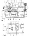
- the sewing machine shown in the drawing has a housing-like base plate 1, an upper arm 2 and a vertical stand 3 connecting them, so that the sewing machine is C-shaped as a whole.
- an arm shaft 4 is mounted, which can be driven by a arranged in the stator 3 main drive motor 5 via a belt drive 6 is.
- a needle bar 7 is further mounted, which carries a needle 8 at its lower end.
- the needle bar 7 is on the arm shaft 4 in the usual manner up and down, so substantially in the z direction, driven.
- the needle bar 7 is further mounted in a needle bar turning and swinging bearing 9, which is rotatably or pivotally driven by a mounted in the base plate 1 rotary bearing drive motor 10 via a shaft 3 mounted in the stator shaft 11 and a belt drive 12, and Although about the central longitudinal axis 13 of the needle bar 7.
- the oscillating drive of the bearing 9 via an electromotive oscillating or zigzag drive motor 14th
- a co-operating with the needle 8 gripper bearing 15 is rotatably mounted in the usual manner, which is also driven by the rotary bearing drive motor 10 via a belt drive 16 synchronously and angle of rotation to the bearing 9.
- xy-table 17 On the base plate 1 designed as a table xy-table 17 is arranged displaceably in the x- and y-direction, which by means of a mounted in the base plate 1 y-drive motor 18 via a spindle-nut drive 19 in the y-direction, ie in sewing machine longitudinal direction, is horizontally displaceable.
- the table 17 is also by means of an x-drive motor 20 also horizontally, but transversely to the y-direction, ie in the x-direction, displaceable.
- a fabric clamp 21 On the table 17, a fabric clamp 21 is arranged.
- a buttonhole cutting device 26 located in the y-direction behind the needle bar 7, a buttonhole cutting device 26.
- This consists essentially of an upper drivable cutting part 27 and a lower anvil 28.
- the upper cutting part 27 has a cutting drive 29, which is connected to a two-armed lever 30, which in turn is connected to a drive rod 31 which is guided vertically displaceably in at least one arranged on the arm 2 guide bearing 32.
- a knife head 33 is mounted, on the underside of a knife 34 is mounted replaceably.
- the anvil is adjustable by means of an adjustment drive 35 between at least two positions under the blade 34, so that - depending on the position of the anvil 28 - different cuts can be performed. Further details of the buttonhole cutting device 26 will become apparent from DE 102 25 511 A, to which reference is made.
- the stand 3 is offset to the rear as seen from the operating side 36; he is located - seen in the x direction - behind the passing through the needle bar 7 y-z plane. In this way, it is possible to hold workpieces 24 in the y-direction by means of the fabric clamp 21 on the table 17, which still extend to the stand 3 and beyond, as indicated in Fig. 3.
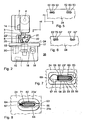
- the sewing machine has - as can be seen in FIG. 4 - a control panel 37, which is provided with an input keyboard designed as input device 38 and a display device 39, a display.
- the control panel 37 is associated with a controller 40 in which a computer 41 and a first buttonhole parameter memory 42 and a second stitching data memory 43 are located.
- the control console 37 downstream computer and this downstream memory 42 and 43 are in turn via an interface 44 and amplifier (driver) 45, 46, 47, 48, 49, 50, 51 with the main drive motor 5, the y-drive motor 18th , the x-drive motor 20, the oscillating or zigzag drive motor 14, the rotary bearing drive motor 10, the cutting drive 29 and the adjustment drive 35, respectively.
- buttons 52 can be sewn in the y-direction without conversion, in both y-directions.
- eyelet button seams 52 running in the sewing direction 24 can be produced in the sewing material part 24, for example, whose eye-shaped seam end section 53 is arranged in advance in the y direction.
- similar eye-buttonhole seams 52 'with eye-shaped seam-end portion 53' trailing in the y-direction can also be generated in a simple manner only by means of a signal to be addressed on the control panel 37.
- the clamp plates 23, 23 'adapted for this purpose are shown in FIG.
- the rectangular area 54 is closed at both ends by means of an approximately circular area 56, 57, wherein in each of these two areas the eye-shaped seam end portion 53 or 53 'is sewn.
- a looper thread not shown, and optionally also a gimp thread, also not shown, consisting of two zigzag beads 59, 60, straight seam portion 55 is a zigzag bars 61, which is still sewn in the rectangular area 54.
- the eye buttonhole seams 52 are to be sewn with the lagging eye-shaped seam end portion 53', then the eye-shaped seam end portion 53 in FIG circular area 57 of the clamping plates 23, 23 'is formed.
- the zigzag latch 61 is then sewn adjacent to the circular region 56.
- the generation of the beads 59, 60 and the zigzag latch 61 is effected exclusively by appropriate use of the oscillating or zigzag drive motor 14 and the y-drive motor 18.
- the generation of the eye-shaped seam end portion 53 takes place with additional use of the pivot bearing.
- lingerie buttonhole seams 62 may also be sewn, for example, with a round bar 63 at one end and a wedge latch 64 at the other end.
- buttonhole seam 52, 62 and its location is first selected, which may be, for example, the seam of an eye buttonhole or a so-called laundry buttonhole. Basically, this concerns buttonhole seams 52, 62 with different end portions, for example, with an eye-shaped seam end portion 53 or a bolt such as round bar 63, wedge-bolt 64, zigzag latch 61 or the like.
- buttonhole parameters are input to the input device 38 and stored in the first memory 42.
- the calculator 41 calculates the actual sewing data such as the stitch coordinates and the number of stitches in the individual seam sections and the like.
- stitching geometry determining sewing data are stored in the second memory 43. If such a buttonhole seam is to be sewn, these data are read from the second memory 43 and control the various drives 5, 18, 20, 14, 10, 29, 35 via the amplifiers 45 to 51.
- a reversed position of a buttonhole already stored with its sewing data is called via a predetermined switch 68 of the input device 38, this automatically triggers conversion of the existing sewing data in the computer 41, which is then stored again in the second memory 43 and be available in a corresponding manner.
- an automatic mirroring of the sewing data takes place, depending on whether a right or left position of a buttonhole is called up. Again, the buttonhole is displayed in its position on the display device 38.
- the anvil 28 is brought by means of the adjustment drive 35 in the corresponding section 69, 70, 71 associated position and then the cutting drive 29 driven.
Landscapes
- Engineering & Computer Science (AREA)
- Textile Engineering (AREA)
- Computer Hardware Design (AREA)
- Microelectronics & Electronic Packaging (AREA)
- Mechanical Engineering (AREA)
- Sewing Machines And Sewing (AREA)
Description
- Die Erfindung betrifft eine Knopfloch-Nähmaschine zur Herstellung von Knopfloch-Nähten mit unterschiedlich ausgebildeten Naht-Endabschnitten in einem Nähgut-Teil.
- An Bekleidungsstücken, wie Mänteln, Sakkos, Blusen usw., die an der Vorderseite mit Knöpfen und Knopflöchern verschlossen werden, befinden sich bei Herren-Bekleidungsstücken die Knopflöcher jeweils im Vergleich zu Damen-Bekleidungsstücken in spiegelbildlicher Anordnung an den Knopfloch-Leisten. Bei solchen Knopflöchern verläuft der von der Nadel der Nähmaschine zugeführte Nadelfaden etwa linienförmig an der äußerlich sichtbaren Seite, auf der in zugeknöpftem Zustand des Bekleidungsstücks der jeweilige Knopf liegt.
- Bei manchen Kleidungsstücken, beispielsweise Strickwesten, werden die Knopflöcher mit ihrer Längsrichtung parallel zur Außenkante des Nähgut-Teils angeordnet. Die Knopflöcher sind also in ihrer Längsrichtung hintereinander angeordnet. Sie weisen unterschiedlich ausgebildete Naht-Endabschnitte auf, also Riegel in verschiedenen Formen, wie Rund-Riegel, Keil-Riegel, Zickzack-Riegel oder Riegel in Augenform.
- Um derartige Knopfloch-Nähte nähen zu können, ist aus der DE 16 60 950 C3 (entsprechend US 3,216,381) eine Knopfloch-Nähmaschine der allgemeinen Gattung bekannt mit einer Grundplatte, einem oberen Arm und einem die Grundplatte mit dem Arm verbindenden Ständer und mit einer auf- und abgehenden, im wesentlichen in einer z-Richtung mittels eines Haupt-Antriebsmotors antreibbaren, im Arm gelagerten, eine Nadel tragenden Nadelstange. Weiterhin weist diese Nähmaschine eine in y-Richtung, also in Maschinen-Längsrichtung, verschiebbare Nähgut-Klammer zum Halten des Nähgut-Teils auf. Der Ständer ist gegenüber einer durch die Nadel gelegten y-z-Ebene zurückversetzt. Durch diese Ausgestaltung kann ein Nähgut-Teil mit seiner Knopfloch-Leiste parallel zur Längsrichtung des Arms, also in Nähmaschinen-Längsrichtung, ohne Behinderung durch den Ständer eingelegt werden. Zur Herstellung der eingangs angesprochenen Knopfloch-Nähte, die jeweils für Damen- und Herren-Bekleidungsstücke spiegelbildlich ausgestaltet sind, müssen jeweils gesonderte Nähmaschinen eingesetzt werden.
- Der Erfindung liegt die Aufgabe zugrunde, eine Knopfloch-Nähmaschine der allgemeinen Gattung so auszugestalten, dass sie in einfacher Weise derart umgestellt werden kann, dass Knopfloch-Nähte mit unterschiedlichen End-Abschnitten seitenverkehrt hergestellt werden können.
- Diese Aufgabe wird erfindungsgemäß durch die Merkmale des Anspruches 1 gelöst. Die Knopfloch-Nähmaschine nach der Erfindung ist derart ausgestaltet, dass spiegelbildlich oder seitenverkehrt angeordnete Knopflöcher ohne größeren Aufwand für eine Programm-Eingabe hergestellt werden können. Somit ist durch ein Einlegen des Nähgut-Teils in der einen oder anderen Richtung, wie beispielsweise auch Kragenspiegel links- oder rechtsliegend, gleichsam per Knopfdruck ein Umrechnen der Näh-Daten, also der Stich-Koordinaten, in sehr flexibler Weise möglich. Die Steuerung veranlasst eine entsprechende Ansteuerung der Antriebsmotoren bzw. Stellorgane. Durch die erfindungsgemäßen Maßnahmen können die für ein Knopfloch bereits gespeicherten Parameter für ein spiegelbildlich angeordnetes Knopfloch verwendet werden. Es erfolgt eine Online-Berechnung der Stich-Koordinaten-Werte für das gewünschte Knopfloch. Ein vorhandener Speicher kann für unterschiedliche Programme verwendet werden. Die Programm-Umstellung ist schnell und einfach auszuführen. MaschinenStillstandszeiten werden reduziert. Es tritt eine Arbeitserleichterung durch einfache Bedienung ein. Es ist eine hohe Betriebssicherheit erreicht, da Fehler infolge von Fehlbedienungen und Fehlprogrammierungen stark reduziert werden.
- Ein Ausführungsbeispiel der Erfindung wird nachfolgend anhand der Zeichnung näher erläutert. Es zeigt
- Fig. 1 eine Seitenansicht einer Knopfloch-Nähmaschine,
- Fig. 2 eine Stirn-Ansicht der Knopfloch-Nähmaschine entsprechend dem Sichtpfeil II in Fig. 1,
- Fig. 3 einen Teil-Horizontal-Schnitt entsprechend der Schnittlinie III-III in Fig. 1,
- Fig. 4 eine schematische Darstellung der Steuerung, des Bedienpultes und der Antriebsmotoren der Nähmaschine,
- Fig. 5 ein Nähgut-Teil mit einer Reihe in einer ersten Richtung genähten Knopflöchern,
- Fig. 6 eine Fig. 5 entsprechende Ansicht des Nähgut-Teils mit in entgegengesetzter Richtung angeordneten Knopflöchern,
- Fig. 7 eine vergrößerte Ansicht eines Augen-Knopflochs mit einem Zickzack-Riegel und
- Fig. 8 eine vergrößerte Ansicht eines Knopflochs mit einem Rund-Riegel und einem Keil-Riegel.
- Die in der Zeichnung dargestellte Nähmaschine weist eine gehäuseartige Grundplatte 1, einen oberen Arm 2 und einen diese verbindenden vertikalen Ständer 3 auf, so dass die Nähmaschine insgesamt C-förmig ausgebildet ist. Im Arm 2 ist eine Armwelle 4 gelagert, die von einem im Ständer 3 angeordneten Haupt-Antriebs-Motor 5 über einen Riementrieb 6 antreibbar ist. Im Arm 2 ist weiterhin eine Nadelstange 7 gelagert, die an ihrem unteren Ende eine Nadel 8 trägt. Die Nadelstange 7 ist über die Armwelle 4 in üblicher Weise auf und ab, also im wesentlichen in z-Richtung, antreibbar. Die Nadelstange 7 ist weiterhin in einem Nadelstangen-Dreh- und Schwing-Lager 9 gelagert, das von einem in der Grundplatte 1 angeordneten Drehlager-Antriebsmotor 10 über eine im Ständer 3 gelagerte Welle 11 und einen Riementrieb 12 dreh- bzw. schwenkantreibbar ist, und zwar um die Mittel-Längs-Achse 13 der Nadelstange 7. Der Schwing-Antrieb des Lagers 9 erfolgt über einen elektromotorischen Schwing- bzw. Zickzack-Antriebsmotor 14.
- In der Grundplatte 1 ist in üblicher Weise ein mit der Nadel 8 zusammenwirkendes Greifer-Lager 15 drehbar gelagert, das vom Drehlager-Antriebsmotor 10 ebenfalls über einen Riementrieb 16 synchron und drehwinkelgleich zum Lager 9 antreibbar ist.
- Auf der Grundplatte 1 ist ein als x-y-Tisch ausgebildeter Tisch 17 in x- und in y-Richtung verschiebbar angeordnet, der mittels eines in der Grundplatte 1 gelagerten y-Antriebsmotors 18 über einen Spindel-Mutter-Trieb 19 in y-Richtung, also in Nähmaschinen-Längsrichtung, horizontal verschiebbar ist. Der Tisch 17 ist weiterhin mittels eines x-Antriebsmotors 20 ebenfalls horizontal, aber quer zur y-Richtung, also in x-Richtung, verschiebbar. Eine derartige Ausgestaltung ist aus der DE 102 33 017 A bekannt. Auf dem Tisch 17 ist eine Nähgut-Klammer 21 angeordnet. Diese weist zwei jeweils an schwenkbaren Lagerhebeln 22, 22' angebrachte Klemmplatten 23, 23' auf, die spiegelsymmetrisch zueinander ausgebildet und angeordnet sind. Mittels der Klemmplatten 23, 23' wird ein Nähgutteil 24 auf eine auf dem Tisch 17 angebrachte Auflageplatte 25 gedrückt. Einzelheiten des Aufbaus und des Antriebs einer solchen Nähgut-Klammer 21 ergeben sich aus der DE 102 16 809 A, auf die insoweit verwiesen wird.
- Des weiteren befindet sich in y-Richtung gesehen hinter der Nadelstange 7 eine Knopfloch-Schneid-Vorrichtung 26. Diese besteht im wesentlichen aus einem oberen antreibbaren Schneid-Teil 27 und einem unteren Amboss 28. Der obere Schneid-Teil 27 weist einen Schneid-Antrieb 29 auf, der mit einem zweiarmigen Hebel 30 verbunden ist, der wiederum mit einer Antriebs-Stange 31 verbunden ist, die in mindestens einem am Arm 2 angeordneten Führungs-Lager 32 vertikal verschiebbar geführt ist. Am unteren Ende der Antriebs-Stange 31 ist ein Messer-Kopf 33 angebracht, an dessen Unterseite ein Messer 34 auswechselbar angebracht ist. Der Amboss ist mittels eines Verstell-Antriebs 35 zwischen mindestens zwei Stellungen unter dem Messer 34 verstellbar, so dass - je nach Stellung des Ambosses 28 - unterschiedliche Schnitte ausgeführt werden können. Weitere Einzelheiten der Knopfloch-Schneid-Vorrichtung 26 ergeben sich aus der DE 102 25 511 A, auf die insoweit verwiesen wird.
- Wie Fig. 2 und Fig. 3 entnehmbar ist, ist der Ständer 3 von der Bedienseite 36 aus gesehen nach hinten versetzt; er befindet sich - in x-Richtung gesehen - hinter der durch die Nadelstange 7 gehenden y-z-Ebene. Auf diese Weise ist es möglich, Nähgutteile 24 in y-Richtung mittels der Nähgut-Klammer 21 auf dem Tisch 17 zu halten, die sich noch bis zum Ständer 3 und darüber hinaus erstrecken, wie in Fig. 3 angedeutet ist.
- Die Nähmaschine weist - wie Fig. 4 entnehmbar ist - ein Bedienpult 37 auf, das mit einer als Eingabe-Tastatur ausgebildeten Eingabe-Einrichtung 38 und einer Anzeige-Einrichtung 39, einem Display, versehen ist. Dem Bedienpult 37 ist eine Steuerung 40 zugeordnet, in der sich ein Rechner 41 und ein erster Speicher 42 für Knopfloch-Parameter und ein zweiter Speicher 43 für Nähdaten befindet. Der dem Bedienpult 37 nachgeordnete Rechner und die diesem nachgeordneten Speicher 42 und 43 sind wiederum über eine Schnittstelle 44 und Verstärker (Treiber) 45, 46, 47, 48, 49, 50, 51 mit dem Haupt-Antriebsmotor 5, dem y-Antriebsmotor 18, dem x-Antriebsmotor 20, dem Schwing- bzw. Zickzack-Antriebsmotor 14, dem Drehlager-Antriebsmotor 10, dem Schneid-Antrieb 29 bzw. dem Verstell-Antrieb 35 verbunden.
- Mittels der geschilderten Merkmale können ohne Umbau unterschiedliche Knopflöcher in y-Richtung genäht werden, und zwar in beiden y-Richtungen. Wie insoweit in den Figuren 5 und 6 dargestellt ist, können in dem Nähgutteil 24 beispielsweise auch in y-Richtung verlaufende Augen-Knopfloch-Nähte 52 erzeugt werden, deren augenförmiger Naht-Endabschnitt 53 in y-Richtung vorlaufend angeordnet ist. Andererseits können ebenfalls auf einfache Weise lediglich durch eine noch anzusprechende Signalgabe am Bedienpult 37 gleichartige Augen-Knopfloch-Nähte 52' mit in y-Richtung nacheilendem augenförmigen Naht-Endabschnitt 53' erzeugt werden. Die hierzu angepassten Klemmplatten 23, 23' sind in Fig. 7 dargestellt. Sie begrenzen zwischen sich einen rechteckförmigen, in y-Richtung gestreckten Bereich 54, in dem der geradlinige Naht-Abschnitt 55 der Knopfloch-Naht 52 genäht wird. Der rechteckförmige Bereich 54 ist beidendig mittels eines etwa kreisförmigen Bereichs 56, 57 abgeschlossen, wobei jeweils in einem dieser beiden Bereiche der augenförmige Naht-Endabschnitt 53 oder 53' genäht wird. Am dem augenförmigen Naht-Endabschnitt 53 oder 53' entgegengesetzten Bereich des durch den Nadelfaden 58, einen nicht dargestellten Greiferfaden und gegebenenfalls einen ebenfalls nicht dargestellten Gimpenfaden gebildeten, aus zwei Zickzack-Raupen 59, 60 bestehenden, geradlinigen Naht-Abschnitts 55 ist ein Zickzack-Riegel 61 ausgebildet, der noch in dem rechteckigen Bereich 54 genäht wird. Wenn anstelle der Augen-Knopfloch-Nähte 52 mit in y-Richtung voreilendem augenförmigen Naht-Endabschnitt 53 die Augen-Knopfloch-Nähte 52' mit nacheilendem augenförmigen Naht-Endabschnitt 53' genäht werden sollen, dann wird dar augenförmige Naht-Endabschnitt 53 in dem kreisförmigen Bereich 57 der Klemmplatten 23, 23' ausgebildet. Der Zickzack-Riegel 61 wird dann benachbart zum kreisförmigen Bereich 56 genäht. Die Erzeugung der Raupen 59, 60 und des Zickzack-Riegels 61 erfolgt ausschließlich durch entsprechenden Einsatz des Schwing- bzw. Zickzack-Antriebsmotors 14 und des y-Antriebsmotors 18. Die Erzeugung des augenförmigen Naht-Endabschnitts 53 erfolgt dagegen unter zusätzlichem Einsatz des Drehlager-Antriebsmotors 10 und des x-Antriebsmotors 20.
- Wie Fig. 8 entnehmbar ist, können auch Wäsche-Knopfloch-Nähte 62 beispielsweise mit einem Rund-Riegel 63 an einem Ende und einem Keil-Riegel 64 am anderen Ende genäht werden. Die Klemmplatten 23a und 23a' sind in diesem Fall so ausgestaltet, dass sie einen die Knopfloch-Naht 62 zwischen sich aufnehmenden Bereich 65 und an den beiden Enden Ausnehmungen 66, 67 zur Aufnahme eines Keil-Riegels 64 aufweisen.
- An der Eingabe-Einrichtung 38 wird zunächst die Art der Knopfloch-Naht 52, 62 und deren Lage ausgewählt, wobei es sich beispielsweise um die Naht eines Augen-Knopfloches oder die eines sogenannten Wäsche-Knopfloches handeln kann. Grundsätzlich betrifft dies Knopfloch-Nähte 52, 62 mit unterschiedlichen End-Abschnitten, beispielsweise also mit einem augenförmigen Naht-Endabschnitt 53 oder einem Riegel wie Rund-Riegel 63, Keil-Riegel 64, Zickzack-Riegel 61 o.dgl.
- Je nach der Auswahl der Art der Knopfloch-Naht und deren Lage erfolgt eine entsprechende bildliche Darstellung an der Anzeige-Einrichtung 39. Anschließend werden an der Eingabe-Einrichtung 38 Knopfloch-Parameter eingegeben, die in dem ersten Speicher 42 abgelegt werden. Auf der Grundlage dieser Knopfloch-Parameter berechnet der Rechner 41 die eigentlichen Nähdaten wie die Stich-Koordinaten und die Zahl der Stiche in den einzelnen Naht-Abschnitten u.dgl.
- Diese die Naht-Geometrie bestimmenden Näh-Daten werden im zweiten Speicher 43 abgelegt. Wenn eine solche Knopfloch-Naht zu nähen ist, werden diese Daten aus dem zweiten Speicher 43 ausgelesen und steuern über die Verstärker 45 bis 51 die verschiedenen Antriebe 5, 18, 20, 14, 10, 29, 35 an.
- Wenn über einen vorgegebenen Schalter 68 der Eingabe-Einrichtung 38 eine umgekehrte Lage eines mit seinen Näh-Daten bereits gespeicherten Knopfloches aufgerufen wird, dann wird hierüber selbsttätig ein Umrechnen der vorhandenen Näh-Daten im Rechner 41 ausgelöst, die dann wieder im zweiten Speicher 43 abgelegt werden und in entsprechender Weise zur Verfügung stehen. Es erfolgt also gleichsam eine automatische Spiegelung der Näh-Daten je nachdem, ob eine Rechts- oder Links-Lage eines Knopflochs aufgerufen wird. Auch hierbei wird das Knopfloch in seiner Lage auf der Anzeige-Einrichtung 38 abgebildet.
- Nach dem Nähen der jeweiligen Knopfloch-Naht wird einerseits der Amboss 28 mittels des Verstell-Antriebs 35 in die dem entsprechenden Schnitt 69, 70, 71 zugeordnete Position gebracht und dann der Schneid-Antrieb 29 angesteuert.
Claims (8)
- Knopfloch-Nähmaschine zur Herstellung von Knopfloch-Nähten mit unterschiedlich ausgebildeten Naht-Endabschnitten in einem Nähgut-Teil (24),- mit einer Grundplatte (1), einem oberen Arm (2) und einem die Grundplatte (1) mit dem Arm (2) verbindenden Ständer (3),- mit einer auf- und abgehenden, im wesentlichen in einer z-Richtung mittels eines Haupt-Antriebsmotors (5) antreibbaren, im Arm (2) gelagerten, eine Nadel (8) tragenden Nadelstange (7),- mit einem mittels eines y-Antriebsmotors (18) in einer y-Richtung verschiebbaren Tisch (17),- mit einer auf dem Tisch (17) angeordneten Nähgut-Klammer (21) zum Halten des Nähgut-Teiles (24) auf dem Tisch (17),- mit einem Antriebsmotor (14, 20) zur Erzeugung einer Relativbewegung in einer x-Richtung zwischen der Nadel (8) und dem Nähgut-Teil (24),- mit einer Steuerung (40) zur Steuerung der Antriebsmotoren (5, 14, 18),-- der eine Eingabe-Einrichtung (38) zur Eingabe von Knopfloch-Parametern zugeordnet ist,-- die einen Rechner (41) zur Berechnung von die jeweilige Knopfloch-Geometrie bestimmenden Näh-Daten aus den Knopfloch-Parametern aufweist,-- die einen Speicher (43) zur Abspeicherung der errechneten Näh-Daten aufweist, und-- die einen in zwei Schaltzustände versetzbaren Schalter (68) aufweist, mittels dessen eine Umrechnung und Abspeicherung der Näh-Daten einer Knopfloch-Naht von einer Links-Lage in eine Rechts-Lage oder umgekehrt auslösbar ist.
- Knopfloch-Nähmaschine nach Anspruch 1, dadurch gekennzeichnet, dass eine Anzeige-Einrichtung (39) zur Ausgabe einer Information entsprechend einer ausgewählten Knopfloch-Lage vorgesehen ist.
- Knopfloch-Nähmaschine nach Anspruch 2, dadurch gekennzeichnet, dass die Anzeige-Einrichtung (39) zur Ausgabe eines Knopfloch-Bildes ausgebildet ist.
- Knopfloch-Nähmaschine nach einem der Ansprüche 1 bis 3, dadurch gekennzeichnet,
dass der Ständer (3) gegenüber einer durch die Nadelstange (7) gelegten y-z-Ebene zurückversetzt ist. - Knopfloch-Nähmaschine nach einem der Ansprüche 1 bis 4, dadurch gekennzeichnet,
dass die Nadelstange (7) in einem Nadelstangen-Dreh- und Schwing-Lager (9) gelagert und mittels eines Drehlager-Antriebsmotors (10) um ihre Mittel-Längs-Achse (13) drehantreibbar ist, und
dass der Drehlager-Antriebsmotor (10) von der Steuerung (40) ansteuerbar ist. - Knopfloch-Nähmaschine nach einem der Ansprüche 1 bis 5, dadurch gekennzeichnet,
dass der Tisch (17) mittels eines x-Antriebsmotors (20) in x-Richtung antreibbar ist, und
dass der x-Antriebsmotor (20) von der Steuerung (40) ansteuerbar ist. - Knopfloch-Nähmaschine nach einem der Ansprüche 1 bis 6, dadurch
gekennzeichnet,
dass eine Knopfloch-Schneid-Vorrichtung (26) vorgesehen ist, deren Schneid-Antrieb (29) von der Steuerung (40) ansteuerbar ist. - Knopfloch-Nähmaschine nach Anspruch 7, dadurch gekennzeichnet, dass die Knopfloch-Schneid-Vorrichtung (26) einen Amboss (28) aufweist, der mittels eines Verstell-Antriebs (35) in mindestens zwei unterschiedliche Stellungen relativ zu einem Messer (34) verstellbar ist, und dass der Verstell-Antrieb (35) von der Steuerung (40) ansteuerbar ist.
Applications Claiming Priority (2)
| Application Number | Priority Date | Filing Date | Title |
|---|---|---|---|
| DE10238708A DE10238708A1 (de) | 2002-08-23 | 2002-08-23 | Knopfloch-Nähmaschine |
| DE10238708 | 2002-08-23 |
Publications (2)
| Publication Number | Publication Date |
|---|---|
| EP1391547A1 EP1391547A1 (de) | 2004-02-25 |
| EP1391547B1 true EP1391547B1 (de) | 2007-01-03 |
Family
ID=30775532
Family Applications (1)
| Application Number | Title | Priority Date | Filing Date |
|---|---|---|---|
| EP03017909A Expired - Lifetime EP1391547B1 (de) | 2002-08-23 | 2003-08-06 | Knopfloch-Nähmaschine |
Country Status (9)
| Country | Link |
|---|---|
| US (1) | US6755139B2 (de) |
| EP (1) | EP1391547B1 (de) |
| JP (1) | JP2004081858A (de) |
| KR (1) | KR101050652B1 (de) |
| CN (1) | CN100445454C (de) |
| AT (1) | ATE350524T1 (de) |
| DE (2) | DE10238708A1 (de) |
| PT (1) | PT1391547E (de) |
| TW (1) | TWI294932B (de) |
Families Citing this family (10)
| Publication number | Priority date | Publication date | Assignee | Title |
|---|---|---|---|---|
| DE10304821B3 (de) * | 2003-02-06 | 2004-02-26 | Dürkopp Adler AG | Knopfloch-Nähmaschine |
| JP2007195807A (ja) * | 2006-01-27 | 2007-08-09 | Juki Corp | 差動送りミシン |
| JP2007252740A (ja) * | 2006-03-24 | 2007-10-04 | Brother Ind Ltd | 穴かがりミシン |
| JP4935179B2 (ja) * | 2006-04-05 | 2012-05-23 | ヤマトミシン製造株式会社 | ボタン付けミシン |
| JP4877627B2 (ja) * | 2006-06-27 | 2012-02-15 | ヤマトミシン製造株式会社 | ボタン付けミシン |
| DE102011005936A1 (de) * | 2011-03-23 | 2012-09-27 | Dürkopp Adler AG | Augenknopfloch-Nähmaschine sowie Verfahren zum Nähen einer einem Gimpfaden aufweisenden Augenknopfloch-Naht |
| CN103290620B (zh) * | 2013-06-27 | 2015-04-08 | 苏州祺尚纺织有限公司 | 一种纽扣孔扫描结构 |
| JP2016086874A (ja) * | 2014-10-30 | 2016-05-23 | ブラザー工業株式会社 | ミシン及びミシンの制御方法 |
| DE102022203472A1 (de) | 2022-04-07 | 2023-10-12 | Dürkopp Adler GmbH | Nähmaschine |
| KR102568751B1 (ko) | 2022-12-22 | 2023-08-18 | 남경식 | 의류 주머니용 단추구멍 재봉 가이드장치 |
Family Cites Families (12)
| Publication number | Priority date | Publication date | Assignee | Title |
|---|---|---|---|---|
| US3216381A (en) * | 1962-04-04 | 1965-11-09 | Necchi Spa | Buttonhole sewing machine |
| US4171671A (en) * | 1978-01-09 | 1979-10-23 | Usm Corporation | Automatic stitching apparatus |
| JPS58112287U (ja) * | 1982-01-26 | 1983-08-01 | 三菱電機株式会社 | 穴かがりミシン |
| IT1231484B (it) * | 1987-07-22 | 1991-12-07 | Tokai Ind Sewing Machine | Macchina per ricamare atta a svolgere operazioni di esecuzione e di controllo dell'operazione di ricamo in accordo con i dati memorizzati |
| JPH01190390A (ja) * | 1988-01-26 | 1989-07-31 | Juki Corp | ボタンホールの縫い方法 |
| JP2595691Y2 (ja) * | 1993-10-25 | 1999-05-31 | ジューキ株式会社 | 鳩目穴かがりミシンのメス装置 |
| DE19807771C1 (de) * | 1998-02-24 | 1999-04-15 | Duerkopp Adler Ag | Augenknopfloch-Nähmaschine |
| DE19916660C1 (de) * | 1999-04-14 | 2000-06-21 | Duerkopp Adler Ag | Knopfloch-Nähmaschine |
| KR100778187B1 (ko) * | 1999-12-06 | 2007-11-27 | 부라더 고교 가부시키가이샤 | 휘감치기 미싱 및 휘감치기 바늘땀 형성 방법 |
| JP3897970B2 (ja) | 2000-09-12 | 2007-03-28 | 株式会社デジタル | エディタ装置およびエディタプログラムを記録した記録媒体 |
| TW496295U (en) | 2001-01-08 | 2002-07-21 | Wen-Ying Liou | Ink filling device for ink cartridge of ink jetting printer |
| DE10216809C1 (de) * | 2002-04-16 | 2003-07-03 | Duerkopp Adler Ag | CNC-gesteuerte Knopfloch-Nähmaschine |
-
2002
- 2002-08-23 DE DE10238708A patent/DE10238708A1/de not_active Withdrawn
-
2003
- 2003-08-06 PT PT03017909T patent/PT1391547E/pt unknown
- 2003-08-06 AT AT03017909T patent/ATE350524T1/de not_active IP Right Cessation
- 2003-08-06 EP EP03017909A patent/EP1391547B1/de not_active Expired - Lifetime
- 2003-08-06 DE DE50306164T patent/DE50306164D1/de not_active Expired - Lifetime
- 2003-08-16 KR KR1020030056675A patent/KR101050652B1/ko not_active Expired - Fee Related
- 2003-08-21 JP JP2003297553A patent/JP2004081858A/ja active Pending
- 2003-08-21 US US10/645,393 patent/US6755139B2/en not_active Expired - Lifetime
- 2003-08-22 TW TW092123163A patent/TWI294932B/zh not_active IP Right Cessation
- 2003-08-22 CN CNB031538002A patent/CN100445454C/zh not_active Expired - Fee Related
Also Published As
| Publication number | Publication date |
|---|---|
| TW200406518A (en) | 2004-05-01 |
| CN1485487A (zh) | 2004-03-31 |
| KR101050652B1 (ko) | 2011-07-19 |
| JP2004081858A (ja) | 2004-03-18 |
| TWI294932B (en) | 2008-03-21 |
| PT1391547E (pt) | 2007-02-28 |
| CN100445454C (zh) | 2008-12-24 |
| DE50306164D1 (de) | 2007-02-15 |
| US20040035342A1 (en) | 2004-02-26 |
| ATE350524T1 (de) | 2007-01-15 |
| EP1391547A1 (de) | 2004-02-25 |
| US6755139B2 (en) | 2004-06-29 |
| DE10238708A1 (de) | 2004-03-04 |
| KR20040018143A (ko) | 2004-03-02 |
Similar Documents
| Publication | Publication Date | Title |
|---|---|---|
| DE4132586C2 (de) | Knopflochnähmaschine | |
| US3747545A (en) | Sewing apparatus for the formation of edge-piping openings | |
| DE102007003449B4 (de) | Automatische Einfassmaschine | |
| DE102008010354B4 (de) | Einfassmaschine | |
| DE10224098A1 (de) | Knopfannäh- und Stielumwickelnähmaschine | |
| EP1391547A1 (de) | Knopfloch-Nähmaschine | |
| DE19916660C1 (de) | Knopfloch-Nähmaschine | |
| EP1722021B1 (de) | Knopfloch-Nähmaschine | |
| DE7605072U1 (de) | Naehaggregat zum bilden von formnaehten | |
| DE10022238B4 (de) | Steuervorrichtung für eine Knopflochnähmaschine | |
| DE102006003866B4 (de) | Einfassnähmaschine | |
| DE102007020139B4 (de) | Einfassmaschine | |
| DE102007020161A1 (de) | Einfassmaschine | |
| DE10060583A1 (de) | Nähmaschine und Verfahren des Steuerns einer Nähgutvorschubeinheit | |
| DE3823945C2 (de) | ||
| DE102004019143B4 (de) | Knopfannäh- und Stielumwickelmaschine | |
| DE68921026T2 (de) | Industrie-Nähmaschine, die gleichzeitig mehrere Nähte ausführen kann. | |
| DE102008010353B4 (de) | Einfassmaschine | |
| DE69120238T2 (de) | Industrie-Nähmaschine, die gleichzeitig verschiedene Nähte ausführen kann | |
| EP1584725B1 (de) | Augen-Knopfloch-Nähmaschine | |
| DE102008047324B4 (de) | Einfassmaschine | |
| DE4135472C1 (de) | ||
| DE102006013285A1 (de) | Einfassnähmaschine | |
| DE102012206063A1 (de) | Knopfannähverfahren und Knopfnähmaschine | |
| DE102005042422B4 (de) | Verfahren zum Annähen eines Knopfes mittels einer Knopfannähmaschine |
Legal Events
| Date | Code | Title | Description |
|---|---|---|---|
| PUAI | Public reference made under article 153(3) epc to a published international application that has entered the european phase |
Free format text: ORIGINAL CODE: 0009012 |
|
| AK | Designated contracting states |
Kind code of ref document: A1 Designated state(s): AT BE BG CH CY CZ DE DK EE ES FI FR GB GR HU IE IT LI LU MC NL PT RO SE SI SK TR |
|
| AX | Request for extension of the european patent |
Extension state: AL LT LV MK |
|
| 17P | Request for examination filed |
Effective date: 20040128 |
|
| AKX | Designation fees paid |
Designated state(s): AT BE BG CH CY CZ DE DK EE ES FI FR GB GR HU IE IT LI LU MC NL PT RO SE SI SK TR |
|
| GRAP | Despatch of communication of intention to grant a patent |
Free format text: ORIGINAL CODE: EPIDOSNIGR1 |
|
| GRAS | Grant fee paid |
Free format text: ORIGINAL CODE: EPIDOSNIGR3 |
|
| GRAA | (expected) grant |
Free format text: ORIGINAL CODE: 0009210 |
|
| AK | Designated contracting states |
Kind code of ref document: B1 Designated state(s): AT BE BG CH CY CZ DE DK EE ES FI FR GB GR HU IE IT LI LU MC NL PT RO SE SI SK TR |
|
| PG25 | Lapsed in a contracting state [announced via postgrant information from national office to epo] |
Ref country code: NL Free format text: LAPSE BECAUSE OF FAILURE TO SUBMIT A TRANSLATION OF THE DESCRIPTION OR TO PAY THE FEE WITHIN THE PRESCRIBED TIME-LIMIT Effective date: 20070103 Ref country code: SI Free format text: LAPSE BECAUSE OF FAILURE TO SUBMIT A TRANSLATION OF THE DESCRIPTION OR TO PAY THE FEE WITHIN THE PRESCRIBED TIME-LIMIT Effective date: 20070103 Ref country code: FI Free format text: LAPSE BECAUSE OF FAILURE TO SUBMIT A TRANSLATION OF THE DESCRIPTION OR TO PAY THE FEE WITHIN THE PRESCRIBED TIME-LIMIT Effective date: 20070103 Ref country code: DK Free format text: LAPSE BECAUSE OF FAILURE TO SUBMIT A TRANSLATION OF THE DESCRIPTION OR TO PAY THE FEE WITHIN THE PRESCRIBED TIME-LIMIT Effective date: 20070103 Ref country code: IE Free format text: LAPSE BECAUSE OF FAILURE TO SUBMIT A TRANSLATION OF THE DESCRIPTION OR TO PAY THE FEE WITHIN THE PRESCRIBED TIME-LIMIT Effective date: 20070103 |
|
| REG | Reference to a national code |
Ref country code: GB Ref legal event code: FG4D Free format text: NOT ENGLISH |
|
| REG | Reference to a national code |
Ref country code: RO Ref legal event code: EPE |
|
| GBT | Gb: translation of ep patent filed (gb section 77(6)(a)/1977) |
Effective date: 20070103 |
|
| REF | Corresponds to: |
Ref document number: 50306164 Country of ref document: DE Date of ref document: 20070215 Kind code of ref document: P |
|
| REG | Reference to a national code |
Ref country code: IE Ref legal event code: FG4D Free format text: LANGUAGE OF EP DOCUMENT: GERMAN |
|
| REG | Reference to a national code |
Ref country code: PT Ref legal event code: SC4A Free format text: AVAILABILITY OF NATIONAL TRANSLATION Effective date: 20070126 |
|
| PG25 | Lapsed in a contracting state [announced via postgrant information from national office to epo] |
Ref country code: SE Free format text: LAPSE BECAUSE OF FAILURE TO SUBMIT A TRANSLATION OF THE DESCRIPTION OR TO PAY THE FEE WITHIN THE PRESCRIBED TIME-LIMIT Effective date: 20070403 |
|
| PG25 | Lapsed in a contracting state [announced via postgrant information from national office to epo] |
Ref country code: BG Free format text: LAPSE BECAUSE OF EXPIRATION OF PROTECTION Effective date: 20070404 |
|
| PG25 | Lapsed in a contracting state [announced via postgrant information from national office to epo] |
Ref country code: ES Free format text: LAPSE BECAUSE OF FAILURE TO SUBMIT A TRANSLATION OF THE DESCRIPTION OR TO PAY THE FEE WITHIN THE PRESCRIBED TIME-LIMIT Effective date: 20070414 |
|
| ET | Fr: translation filed | ||
| NLV1 | Nl: lapsed or annulled due to failure to fulfill the requirements of art. 29p and 29m of the patents act | ||
| REG | Reference to a national code |
Ref country code: IE Ref legal event code: FD4D |
|
| PLBE | No opposition filed within time limit |
Free format text: ORIGINAL CODE: 0009261 |
|
| STAA | Information on the status of an ep patent application or granted ep patent |
Free format text: STATUS: NO OPPOSITION FILED WITHIN TIME LIMIT |
|
| 26N | No opposition filed |
Effective date: 20071005 |
|
| BERE | Be: lapsed |
Owner name: DURKOPP ADLER A.G. Effective date: 20070831 |
|
| REG | Reference to a national code |
Ref country code: CH Ref legal event code: PL |
|
| PG25 | Lapsed in a contracting state [announced via postgrant information from national office to epo] |
Ref country code: MC Free format text: LAPSE BECAUSE OF NON-PAYMENT OF DUE FEES Effective date: 20070831 Ref country code: CH Free format text: LAPSE BECAUSE OF NON-PAYMENT OF DUE FEES Effective date: 20070831 Ref country code: GR Free format text: LAPSE BECAUSE OF FAILURE TO SUBMIT A TRANSLATION OF THE DESCRIPTION OR TO PAY THE FEE WITHIN THE PRESCRIBED TIME-LIMIT Effective date: 20070404 Ref country code: LI Free format text: LAPSE BECAUSE OF NON-PAYMENT OF DUE FEES Effective date: 20070831 |
|
| PG25 | Lapsed in a contracting state [announced via postgrant information from national office to epo] |
Ref country code: BE Free format text: LAPSE BECAUSE OF NON-PAYMENT OF DUE FEES Effective date: 20070831 |
|
| PG25 | Lapsed in a contracting state [announced via postgrant information from national office to epo] |
Ref country code: AT Free format text: LAPSE BECAUSE OF NON-PAYMENT OF DUE FEES Effective date: 20070806 |
|
| PG25 | Lapsed in a contracting state [announced via postgrant information from national office to epo] |
Ref country code: EE Free format text: LAPSE BECAUSE OF FAILURE TO SUBMIT A TRANSLATION OF THE DESCRIPTION OR TO PAY THE FEE WITHIN THE PRESCRIBED TIME-LIMIT Effective date: 20070103 |
|
| PG25 | Lapsed in a contracting state [announced via postgrant information from national office to epo] |
Ref country code: CY Free format text: LAPSE BECAUSE OF FAILURE TO SUBMIT A TRANSLATION OF THE DESCRIPTION OR TO PAY THE FEE WITHIN THE PRESCRIBED TIME-LIMIT Effective date: 20070103 |
|
| PG25 | Lapsed in a contracting state [announced via postgrant information from national office to epo] |
Ref country code: LU Free format text: LAPSE BECAUSE OF NON-PAYMENT OF DUE FEES Effective date: 20070806 |
|
| PG25 | Lapsed in a contracting state [announced via postgrant information from national office to epo] |
Ref country code: HU Free format text: LAPSE BECAUSE OF FAILURE TO SUBMIT A TRANSLATION OF THE DESCRIPTION OR TO PAY THE FEE WITHIN THE PRESCRIBED TIME-LIMIT Effective date: 20070704 |
|
| PGFP | Annual fee paid to national office [announced via postgrant information from national office to epo] |
Ref country code: SK Payment date: 20100802 Year of fee payment: 8 |
|
| PGFP | Annual fee paid to national office [announced via postgrant information from national office to epo] |
Ref country code: GB Payment date: 20100823 Year of fee payment: 8 |
|
| PGFP | Annual fee paid to national office [announced via postgrant information from national office to epo] |
Ref country code: FR Payment date: 20110829 Year of fee payment: 9 Ref country code: PT Payment date: 20110726 Year of fee payment: 9 |
|
| GBPC | Gb: european patent ceased through non-payment of renewal fee |
Effective date: 20110806 |
|
| PG25 | Lapsed in a contracting state [announced via postgrant information from national office to epo] |
Ref country code: SK Free format text: LAPSE BECAUSE OF NON-PAYMENT OF DUE FEES Effective date: 20110806 |
|
| REG | Reference to a national code |
Ref country code: SK Ref legal event code: MM4A Ref document number: E 1717 Country of ref document: SK Effective date: 20110806 |
|
| PG25 | Lapsed in a contracting state [announced via postgrant information from national office to epo] |
Ref country code: GB Free format text: LAPSE BECAUSE OF NON-PAYMENT OF DUE FEES Effective date: 20110806 |
|
| PGFP | Annual fee paid to national office [announced via postgrant information from national office to epo] |
Ref country code: IT Payment date: 20120825 Year of fee payment: 10 |
|
| REG | Reference to a national code |
Ref country code: PT Ref legal event code: MM4A Free format text: LAPSE DUE TO NON-PAYMENT OF FEES Effective date: 20130206 |
|
| REG | Reference to a national code |
Ref country code: FR Ref legal event code: ST Effective date: 20130430 |
|
| PG25 | Lapsed in a contracting state [announced via postgrant information from national office to epo] |
Ref country code: PT Free format text: LAPSE BECAUSE OF NON-PAYMENT OF DUE FEES Effective date: 20130206 |
|
| PG25 | Lapsed in a contracting state [announced via postgrant information from national office to epo] |
Ref country code: FR Free format text: LAPSE BECAUSE OF NON-PAYMENT OF DUE FEES Effective date: 20120831 |
|
| PG25 | Lapsed in a contracting state [announced via postgrant information from national office to epo] |
Ref country code: IT Free format text: LAPSE BECAUSE OF NON-PAYMENT OF DUE FEES Effective date: 20130806 |
|
| PGFP | Annual fee paid to national office [announced via postgrant information from national office to epo] |
Ref country code: RO Payment date: 20180801 Year of fee payment: 16 |
|
| PGFP | Annual fee paid to national office [announced via postgrant information from national office to epo] |
Ref country code: CZ Payment date: 20180725 Year of fee payment: 16 Ref country code: TR Payment date: 20180726 Year of fee payment: 16 |
|
| PGFP | Annual fee paid to national office [announced via postgrant information from national office to epo] |
Ref country code: DE Payment date: 20181024 Year of fee payment: 16 |
|
| REG | Reference to a national code |
Ref country code: DE Ref legal event code: R119 Ref document number: 50306164 Country of ref document: DE |
|
| PG25 | Lapsed in a contracting state [announced via postgrant information from national office to epo] |
Ref country code: RO Free format text: LAPSE BECAUSE OF NON-PAYMENT OF DUE FEES Effective date: 20190806 |
|
| PG25 | Lapsed in a contracting state [announced via postgrant information from national office to epo] |
Ref country code: CZ Free format text: LAPSE BECAUSE OF NON-PAYMENT OF DUE FEES Effective date: 20190806 |
|
| PG25 | Lapsed in a contracting state [announced via postgrant information from national office to epo] |
Ref country code: DE Free format text: LAPSE BECAUSE OF NON-PAYMENT OF DUE FEES Effective date: 20200303 |
|
| PG25 | Lapsed in a contracting state [announced via postgrant information from national office to epo] |
Ref country code: TR Free format text: LAPSE BECAUSE OF NON-PAYMENT OF DUE FEES Effective date: 20190806 |