EP1384812B1 - Betonschwelle mit Führungsplatten für den Schienenfuss - Google Patents
Betonschwelle mit Führungsplatten für den Schienenfuss Download PDFInfo
- Publication number
- EP1384812B1 EP1384812B1 EP03015844A EP03015844A EP1384812B1 EP 1384812 B1 EP1384812 B1 EP 1384812B1 EP 03015844 A EP03015844 A EP 03015844A EP 03015844 A EP03015844 A EP 03015844A EP 1384812 B1 EP1384812 B1 EP 1384812B1
- Authority
- EP
- European Patent Office
- Prior art keywords
- twisting
- guide plates
- support area
- prevention
- concrete
- Prior art date
- Legal status (The legal status is an assumption and is not a legal conclusion. Google has not performed a legal analysis and makes no representation as to the accuracy of the status listed.)
- Expired - Lifetime
Links
Images


Classifications
-
- E—FIXED CONSTRUCTIONS
- E01—CONSTRUCTION OF ROADS, RAILWAYS, OR BRIDGES
- E01B—PERMANENT WAY; PERMANENT-WAY TOOLS; MACHINES FOR MAKING RAILWAYS OF ALL KINDS
- E01B1/00—Ballastway; Other means for supporting the sleepers or the track; Drainage of the ballastway
- E01B1/002—Ballastless track, e.g. concrete slab trackway, or with asphalt layers
- E01B1/004—Ballastless track, e.g. concrete slab trackway, or with asphalt layers with prefabricated elements embedded in fresh concrete or asphalt
-
- E—FIXED CONSTRUCTIONS
- E01—CONSTRUCTION OF ROADS, RAILWAYS, OR BRIDGES
- E01B—PERMANENT WAY; PERMANENT-WAY TOOLS; MACHINES FOR MAKING RAILWAYS OF ALL KINDS
- E01B3/00—Transverse or longitudinal sleepers; Other means resting directly on the ballastway for supporting rails
- E01B3/28—Transverse or longitudinal sleepers; Other means resting directly on the ballastway for supporting rails made from concrete or from natural or artificial stone
-
- E—FIXED CONSTRUCTIONS
- E01—CONSTRUCTION OF ROADS, RAILWAYS, OR BRIDGES
- E01B—PERMANENT WAY; PERMANENT-WAY TOOLS; MACHINES FOR MAKING RAILWAYS OF ALL KINDS
- E01B9/00—Fastening rails on sleepers, or the like
- E01B9/02—Fastening rails, tie-plates, or chairs directly on sleepers or foundations; Means therefor
- E01B9/28—Fastening on wooden or concrete sleepers or on masonry with clamp members
Definitions
- the invention relates to a concrete sleeper with elastic rail support for a ballast track or a fixed carriageway, with a formed between a rail and lateral, elevated shoulders of the concrete sleeper substantially flat support area, which has no transverse beads, are arranged on the VerFstofftechnischmaschinen having guide plates ,
- both Monoblockschwellen, as well as two-block sleepers for gravel and solid roads are introduced in addition to the raised shoulders of the threshold continuous, relatively deep beads in the concrete body, which serve to receive a corresponding protruding rib formed as an angle guide plate guide rails.
- a two-bar concrete sleeper with elastic rail support for a tram is known, the sleeper having a support area with lateral raised shoulders. Track edges of guide plates together with fastening screws prevent the rail from twisting.
- the invention is therefore the object of a concrete sleeper of the type mentioned in such a way that both simpler gargiemigere guide plates can be used, and in particular cumbersome to produce, provided with high bumps, Formeinliegemaschine can be avoided.
- the invention is based on the finding that these anti-rotation ribs can develop only a conditional additional Verformtik für given the concern of the guide plates on the raised shoulders, which can be achieved in the same way in with significantly less effort by protruding Vercardstoffschschhöcker.
- the support area in the region of each guide plate preferably has two lateral Verwarschhöcker, which engage in corresponding recesses of the guide plate.
- Verhowschschschanker can be concreted both at the threshold, as well as be formed by pre-formed recesses in the concrete body dowels, in particular plastic dowels.
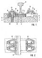
- the Fig. 1 and 2 show a conventional highly elastic rail fastener for fixed carriageways with a arranged between two raised shoulders 1 of the concrete body 2 of the threshold rail support portion 3, which has in addition to a flat central portion two laterally across the threshold traversing deep beads 4, for receiving rib-shaped angled portions 5 of the angled guide plates 6 serve.
- These angle guide plates 6 are the rail foot 7 of the rail 8 laterally and are based on the other side of the shoulders 1 of the concrete body.
- an intermediate plate 9 is firstly arranged for the highly elastic mounting of the rail 8 and on this a base plate 10, on which, in turn, a further 2 to 12 mm thick intermediate layer 11 is arranged under the rail foot 7.
- the usual W-shaped clamps are referred to, with the help of sleeper screws 13 can be fixed, which in turn engage in screw plug 14 in the concrete body 2 of the threshold.
- Fig. 2 on the left is the pre-assembled position and in Fig. 2 on the right the assembled position of the rail fastening parts shown.
- FIGS. 7 and 8 show a variant in which instead of concreted Vermosterrorismhöcker in prefabricated recesses 17 of the concrete body 2 pressed or used in the production with concreted plastic dowels 18 as Vermosterrorismhöcker, which engage in corresponding recesses 19 of the guide plates.
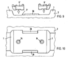
- FIGS. 9 and 10 show an embodiment in which in the support area 3 'for the rails centrally arranged, the guide plates on the inside limiting ridge-shaped elevations 20 are formed, which ensure in conjunction with the shoulders 1 an excellent protection against twisting the guide plates 6'.
- FIGS. 13 and 14 is different from that FIGS. 11 and 12 in that the bumps 22 'are arranged not offset on the outside of the guide plates 6' but in the region of their inner side facing the rail foot and accordingly also the depressions 21 'are further offset inwards from the shoulders.
Landscapes
- Engineering & Computer Science (AREA)
- Architecture (AREA)
- Civil Engineering (AREA)
- Structural Engineering (AREA)
- Mechanical Engineering (AREA)
- Railway Tracks (AREA)
- Machines For Laying And Maintaining Railways (AREA)
- Road Paving Structures (AREA)
- Manufacturing Of Tubular Articles Or Embedded Moulded Articles (AREA)
Description
- Die Erfindung bezieht sich auf eine Betonschwelle mit elastischer Schienenauflagerung für einen Schotteroberbau oder eine feste Fahrbahn, mit einem zwischen einem Schienenfuß und seitlichen, erhöhten Schultern der Betonschwelle ausgebildeten im Wesentlichen ebenen Auflagebereich, der keine quer verlaufenden Sicken aufweist, auf dem Verdrehschutzeinrichtungen aufweisende Führungsplatten angeordnet sind.
- Bei allen üblichen Betonschwellen, sowohl Monoblockschwellen, als auch Zweiblockschwellen für Schotter und feste Fahrbahnen sind neben den hochgezogenen Schultern der Schwelle durchlaufende, relativ tiefe Sicken in den Betonkörper eingebracht, die zur Aufnahme einer entsprechenden vorstehenden Rippe der als Winkelführungsplatte ausgebildeten Führungsschienen dienen.
- Diese Ausbildung hat u. a. den Nachteil, dass beim Herstellen der Betonschwellen in den Gießformen Einlegeteile mit hohen Rippen zur Ausformung der Sicken eingebracht werden müssen. Diese Einlegeteile können nur aus sehr hohen Platten hergestellt werden, die entsprechend tief ausgefräst werden müssen. Dies bedeutet sowohl einen erheblichen Materialverlust des sehr teueren Materials dieser Einlegeteile als auch einen sehr hohen Bearbeitungsaufwand, noch dazu, nachdem die Sicken innen und außen unterschiedliche Krümmungsradien aufweisen.
- Aus der
DE-A-19848928 ist eine Zweiblockbetonschwelle mit elastischer Schienenauflagerung für eine Straßenbahn bekannt, wobei die Schwelle einen Auflagebereich mit seitlichen hochgezogenen Schultern aufweist. Spurkanten von Führungsplatten verhindern gemeinsam mit Befestigungsschrauben eine Verdrehung der Schiene. - In der
US-A-1662402 wird eine Betonschwelle offenbart, die einen im Wesentlichen ebenen Auflagebereich mit hochgezogenen Schultern aufweist. Auf dem Auflagerbereich ist eine Auflagerplatte angeordnet, auf der eine Verdrehschutzplatte verschraubt ist, die den Schienenfuß hält. - Der Erfindung liegt daher die Aufgabe zugrunde, eine Betonschwelle der eingangs genannten Art so auszugestalten, dass sowohl einfachere kleinräumigere Führungsplatten eingesetzt werden können, als auch insbesondere umständlich zu fertigende, mit hohen Höckern versehene, Formeinliegeteile vermieden werden können.
- Zur Lösung dieser Aufgabe ist bei einer Betonschwelle der eingangs genannten Art erfindungsgemäß vorgesehen, dass die Verdrehschutzeinrichtungen entweder als im Auflagebereich angeordnete Verdrehschutzvertiefungen, in die Verdrehschutzhöcker der Führungsplatten eingreifen, oder als auf dem Auflagebereich angeordnete Verdrehschutzhöcker, die in Aussparungen der Führungsplatten eingreifen, ausgebildet sind.
- Durch den Verzicht auf die bisher grundsätzlich vorgesehenen Sicken entfallen sowohl die aufwändig herzustellenden Einlegeteile der Gießformen zur Herstellung der Betonschwellen und es ergibt sich darüber hinaus die Möglichkeit der Verwendung einfacherer Führungsplatten ohne die hohen Verdrehschutzrippen.
- Der Erfindung liegt dabei die Erkenntnis zugrunde, dass diese Verdrehschutzrippen angesichts des Anliegens der Führungsplatten an den hochgezogenen Schultern nur eine bedingte zusätzliche Verdrehschutzwirkung entfalten können, wobei diese in gleicher Weise in mit erheblich geringerem Aufwand durch überstehende Verdrehschutzhöcker erreicht werden kann.
- Neben der Möglichkeit dass der Auflagebereich mit mittig angeordenten, die Führungsplatten innenseitig begrenzenden Erhöhungen versehen ist, kann in Ausgestaltung der Erfindung auch vorgesehen sein, dass der Auflagebereich im Bereich jeder Führungsplatte vorzugsweise zwei seitliche Verdrehschutzhöcker aufweist, die in entsprechende Aussparungen der Führungsplatte eingreifen.
- Dabei können diese Verdrehschutzhöcker sowohl an der Schwelle anbetoniert sein, als auch durch in vorgefertigte Ausnehmungen des Betonkörpers eingedrückte Dübel, insbesondere Kunststoffdübel, gebildet sein.
- Schließlich liegt es auch noch im Rahmen der Erfindung, anstelle der Verdrehschutzhöcker kleine Verdrehschutzvertiefungen im Bereich der seitlichen Ränder des Auflagebereichs vorzusehen, in die entsprechende Höcker der Verdrehschutzplatte eingreifen.
- Weitere Vorteile, Merkmale und Einzelheiten der Erfindung ergeben sich aus der nachfolgenden Beschreibung einiger Ausführungsbeispiele sowie anhand der Zeichnung. Dabei zeigen:
- Fig. 1
- einen Teilschnitt durch eine herkömmliche hochelastische Schienenbefestigung für feste Fahrbahnen,
- Fig. 2
- eine Draufsicht auf die Schienenbefestigung nach
Fig. 1 , - Fig. 3 bis 14
- Ansichten und zugehörige Aufsichten von SchienenAuflagebereichen erfindungsgemäßer Betonschwellen mit unterschiedlich ausgebildeten Verdrehschutzhöckern.
- Die
Fig. 1 und 2 zeigen eine herkömmliche hochelastische Schienenbefestigung für feste Fahrbahnen mit einem zwischen zwei hochgezogenen Schultern 1 des Betonkörpers 2 der Schwelle angeordneten Schienen-Auflagebereich 3, der neben einem ebenen Mittelabschnitt zwei seitlich quer zur Schwelle durchlaufende tiefe Sicken 4 aufweist, die zur Aufnahme rippenförmiger Abwinklungen 5 der Winkelführungsplatten 6 dienen. Diese Winkelführungsplatten 6 liegen dem Schienenfuß 7 der Schiene 8 seitlich an und stützen sich auf der anderen Seite an den Schultern 1 des Betonkörpers ab. Auf dem Schienen-Auflagebereich 3 ist zur hochelastischen Lagerung der Schiene 8 zunächst eine Zwischenplatte 9 und auf dieser eine Grundplatte 10 angeordnet, auf der schließlich wiederum eine weitere 2 bis 12 mm dicke Zwischenlage 11 unter dem Schienenfuß 7 angeordnet ist. Mit 12 sind die üblichen W-förmigen Spannklemmen bezeichnet, die mithilfe von Schwellenschrauben 13 befestigt werden können, die ihrerseits in Schraubdübel 14 im Betonkörper 2 der Schwelle eingreifen. - In
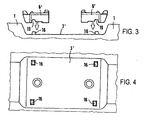
Fig. 2 links ist dabei die vormontierte Stellung und inFig. 2 rechts die montierte Stellung der Schienenbefestigungsteile dargestellt. - Für die meisten Ausführungsformen ist der durch die hochgezogenen Schultern 1 gegebene Verdrehschutz für die aufgelegten Führungsplatten ausreichend. Um aber - insbesondere auch im vormontierten Zustand - einen noch besseren Verdrehschutz etwa entsprechend dem wie bei den herkömmlichen Platten mit Rippen, die in tiefe Sicken der Betonschwelle eingreifen, zu erhalten, können auf dem ebenen Auflagebereich 3' im Bereich jeder Führungsplatte zwei seitliche Verdrehschutzhöcker 16 angeordnet sein, die entweder wie in den
Fig. 3 und 4 bzw. den lediglich geometrisch etwas anders ausgebildeten und angeordneten Höckern 16' in denFig. 5 und 6 gestaltet sind und beispielsweise auf den Auflagebereich 3' aufbetoniert sind. - Die
Fig. 7 und 8 zeigen eine Variante, bei der anstelle aufbetonierter Verdrehschutzhöcker in vorgefertigte Ausnehmungen 17 des Betonkörpers 2 eingedrückte oder bei der Fertigung mit einbetonierte Kunststoffdübel 18 als Verdrehschutzhöcker verwendet werden, die in entsprechende Ausnehmungen 19 der Führungsplatten eingreifen. - Die
Fig. 9 und 10 zeigen schließlich eine Ausführungsform, bei der im Auflagebereich 3' für die Schienen mittig angeordnete, die Führungsplatten innenseitig begrenzende stegförmige Erhöhungen 20 angeformt sind, die in Verbindung mit den Schultern 1 einen vorzüglichen Verdrehschutz für die Führungsplatten 6' gewährleisten. - In den
Fig. 11 bis 12 ist eine Ausführungsvariante gezeigt, bei der das Schienen-Auflager 3 im Bereich der hochgezogenen Rundung zu den Schultern 1 mit kurzen im Bereich der Außenränder des Schienen-Auflagers 3' angeordneten relativ niedrigen Vertiefungen 21 vorgesehen sind, in welche entsprechend geformte über die untere Auflagefläche der Führungsplatte 6' überstehende Höcker 22 eingreifen. - Das Ausführungsbeispiel nach den
Fig. 13 und 14 unterscheidet sich von dem nachFig. 11 und 12 dadurch, dass die Höcker 22' nicht an der Außenseite der Führungsplatten 6' sondern im Bereich ihrer dem Schienenfuß zugekehrten Innenseite und dementsprechend auch die Vertiefungen 21' weiter von den Schultern nach innen versetzt angeordnet sind.
Claims (7)
- Betonschwelle mit elastischer Schienenauflagerung für einen Schotteroberbau oder eine feste Fahrbahn, mit einem zwischen einem Schienenfuß und seitlichen, erhöhten Schultern (1) der Betonschwelle ausgebildeten im Wesentlichen ebenen Auflagebereich (3'), der keine quer verlaufenden Sicken aufweist, auf dem Verdrehschutzeinrichtungen aufweisende Führungsplatten (6') angeordnet sind, dadurch gekennzeichnet, dass die Verdrehschutzeinrichtungen entweder als im Auflagebereich (3') angeordnete Verdrehschutzvertiefungen (21, 21'), in die Verdrehschutzhöcker (22, 22') der Führungsplatten (6') eingreifen, oder als auf dem Auflagebereich (3') angeordnete Verdrehschutzhöcker (16, 16', 18), die in Aussparungen (19, 19', 19") der Führungsplatten (6') eingreifen, ausgebildet sind.
- Betonschwelle nach Anspruch 1, dadurch gekennzeichnet, dass der Auflagebereich (3') im Bereich seiner Außenkanten Verdrehschutzvertiefungen (21, 21') aufweist.
- Betonschwelle nach Anspruch 1, dadurch gekennzeichnet, dass der Auflagebereich (3') mit mittig angeordneten, die Führungsplatten (6') innenseitig begrenzenden Erhöhungen (20) versehen ist.
- Betonschwelle nach einem der vorangehenden Ansprüche, dadurch gekennzeichnet, dass der Auflagebereich (3') im Bereich jeder Führungsplatte (6') vorzugsweise zwei seitliche Verdrehschutzhöcker (16, 16', 18) aufweist, die in die entsprechenden Aussparungen der Führungsplatten (19, 19', 19") eingreifen.
- Betonschwelle nach einem der vorangehenden Ansprüche, dadurch gekennzeichnet, dass die Verdrehschutzhöcker (16, 16') anbetoniert sind.
- Betonschwelle nach Anspruch 4, dadurch gekennzeichnet, dass die Verdrehschutzhöcker (18) durch in vorgefertigte Ausnehmungen (17) der Auflagefläche (3') des Betonkörpers (2) eingedrückte oder bei der Fertigung einbetonierte Dübel, insbesondere Kunststoffdübel, gebildet sind.
- Betonschwelle nach einem der vorangehenden Ansprüche, dadurch gekennzeichnet, dass sie als Zweiblockbetonschwelle ausgebildet ist.
Priority Applications (1)
| Application Number | Priority Date | Filing Date | Title |
|---|---|---|---|
| SI200331529T SI1384812T1 (sl) | 2002-07-25 | 2003-07-11 | Betonski prag z vodilnimi ploĺ äśami za nogo tirnice |
Applications Claiming Priority (2)
| Application Number | Priority Date | Filing Date | Title |
|---|---|---|---|
| DE10233784 | 2002-07-25 | ||
| DE10233784A DE10233784B4 (de) | 2002-07-25 | 2002-07-25 | Betonschwelle |
Publications (3)
| Publication Number | Publication Date |
|---|---|
| EP1384812A2 EP1384812A2 (de) | 2004-01-28 |
| EP1384812A3 EP1384812A3 (de) | 2004-09-15 |
| EP1384812B1 true EP1384812B1 (de) | 2008-12-10 |
Family
ID=29796558
Family Applications (1)
| Application Number | Title | Priority Date | Filing Date |
|---|---|---|---|
| EP03015844A Expired - Lifetime EP1384812B1 (de) | 2002-07-25 | 2003-07-11 | Betonschwelle mit Führungsplatten für den Schienenfuss |
Country Status (15)
| Country | Link |
|---|---|
| US (1) | US7156319B2 (de) |
| EP (1) | EP1384812B1 (de) |
| JP (1) | JP2004060438A (de) |
| KR (1) | KR100622623B1 (de) |
| CN (1) | CN1249301C (de) |
| AT (1) | ATE417153T1 (de) |
| BR (1) | BR0302462A (de) |
| CA (1) | CA2435645C (de) |
| DE (2) | DE10233784B4 (de) |
| DK (1) | DK1384812T3 (de) |
| ES (1) | ES2316673T3 (de) |
| MY (1) | MY134728A (de) |
| PT (1) | PT1384812E (de) |
| SI (1) | SI1384812T1 (de) |
| TW (1) | TWI251045B (de) |
Families Citing this family (44)
| Publication number | Priority date | Publication date | Assignee | Title |
|---|---|---|---|---|
| DE102004033723B4 (de) * | 2004-07-13 | 2009-09-17 | Vossloh-Werke Gmbh | Federelement und System für die Befestigung von Schienen |
| DE102005054820A1 (de) * | 2005-11-15 | 2007-05-24 | Rail.One Gmbh | Feste Fahrbahn für Schienenfahrzeuge |
| DE202006009340U1 (de) * | 2006-06-14 | 2006-08-17 | Seifert, Dietrich | Vorrichtung zur Lagesicherung und Führung von Schienen |
| US7942342B2 (en) | 2007-04-25 | 2011-05-17 | Scott Powers | Railway tie of non-homogeneous cross section useful in environments deleterious to timber |
| US8430334B1 (en) | 2007-04-25 | 2013-04-30 | Jonathan Jaffe | Railroad tie of non-homogeneous cross section useful in environments deleterious to timber |
| DE102007025708B4 (de) * | 2007-06-01 | 2009-06-18 | Schwihag Ag | Kraftschlüssige elastische Schienenbefestigung für Gleisanlagen |
| FR2921392B1 (fr) * | 2007-09-20 | 2012-10-26 | Sateba Systeme Vagneux | Plot comportant au moins une semelle, traverse et ensemble comportant un rail correspondant |
| DE102007053901B3 (de) * | 2007-11-09 | 2009-05-20 | Db Netz Ag | Vorrichtung zur Montage und Demontage eines Befestigungsmittels, insbesondere eines Schienenbefestigungsmittels auf einem Tragkörper |
| HRP20070525A2 (hr) * | 2007-11-15 | 2010-02-28 | Debeljak Tomislav | Elastična kopča i postupak pričvrščivanja tračnica na željezničke pragove |
| DE102008003744B3 (de) * | 2008-01-10 | 2009-06-04 | Vossloh-Werke Gmbh | Abstützung für ein System zum Befestigen einer Schiene und System zum Befestigen einer Schiene |
| DE102008028093A1 (de) * | 2008-06-13 | 2009-12-17 | Wirthwein Ag | Stützpunkt und Befestigung für Schienen auf einer Holzschwelle |
| HK1134632A2 (zh) * | 2008-10-28 | 2010-04-30 | Italian-Thai Development Public Company Limited | 预制轨道基座 |
| DE202009004399U1 (de) * | 2009-02-11 | 2009-06-25 | Vossloh-Werke Gmbh | Führungsplatte für ein System zum Befestigen einer Schiene auf einem Untergrund und ein eine solche Führungsplatte umfassendes System |
| DE102009041848A1 (de) * | 2009-09-18 | 2011-03-24 | Vossloh-Werke Gmbh | System zum Befestigen einer Schiene auf einem festen Untergrund und Befestigung einer Schiene |
| DE202009014434U1 (de) * | 2009-09-18 | 2010-02-11 | Vossloh-Werke Gmbh | Unterlegplatte für die Befestigung einer Schiene auf einem festen Untergrund und Befestigung einer Schiene |
| US8919661B2 (en) * | 2010-08-24 | 2014-12-30 | Vossloh-Werke Gmbh | System for fastening a rail and method for renovating a rail fastening point |
| US20130115399A1 (en) | 2010-10-27 | 2013-05-09 | Richard W. Roberts | In-situ foam core articles |
| US9346237B2 (en) | 2010-10-27 | 2016-05-24 | Richard W. Roberts | Recyclable plastic structural articles and method of manufacture |
| US8342420B2 (en) | 2010-10-27 | 2013-01-01 | Roberts Jr Richard W | Recyclable plastic structural articles and method of manufacture |
| DE102010060745A1 (de) * | 2010-11-23 | 2012-05-24 | Vossloh-Werke Gmbh | Führungsplatte zum seitlichen Führen einer Schiene und System zum Befestigen einer Schiene |
| US9080291B2 (en) | 2011-07-01 | 2015-07-14 | Jonathan E. Jaffe | Embedded receiver for fasteners |
| US8727230B2 (en) * | 2011-07-15 | 2014-05-20 | Vossloh-Werke Gmbh | System for fastening a rail to a sleeper |
| AU2011204811B2 (en) * | 2011-07-18 | 2016-05-26 | Vossloh-Werke Gmbh | System for Fastening a Rail to a Sleeper |
| US9272484B2 (en) | 2012-01-25 | 2016-03-01 | Richard W. Roberts, JR. | Structural plastic articles, method of use, and methods of manufacture |
| US9102086B2 (en) | 2012-03-28 | 2015-08-11 | Richard W. Roberts | In-situ foam core structural articles and methods of manufacture of profiles |
| US8840819B2 (en) | 2012-03-28 | 2014-09-23 | Richard W. Roberts, JR. | In-situ foam core structural energy management system and method of manufacture |
| US10207606B2 (en) | 2012-03-28 | 2019-02-19 | Richard W. Roberts | Recyclable plastic structural articles and method of manufacture |
| US9073462B2 (en) | 2012-03-28 | 2015-07-07 | Richard W. Roberts | In-situ foam core vehicle seating system and method of manufacture |
| US8708177B2 (en) | 2012-03-29 | 2014-04-29 | Richard W. Roberts | In-situ foam core dielectrically-resistant systems and method of manufacture |
| DE102012014500A1 (de) * | 2012-07-23 | 2014-01-23 | Schwihag Ag | Schienenbefestigungssystem für Übergangsbereiche |
| EA027349B1 (ru) * | 2012-10-31 | 2017-07-31 | Швихаг Аг | Пружинный элемент для закрепления рельсов |
| US10328662B2 (en) | 2012-11-01 | 2019-06-25 | Richard W. Roberts | In-situ foam core stress mitigation component and method of manufacture |
| GB2510419B (en) * | 2013-02-04 | 2020-02-05 | Pandrol Ltd | A railway rail anchoring device |
| USD756844S1 (en) * | 2013-03-15 | 2016-05-24 | L.B. Foster Company | Curve block |
| US9271610B2 (en) | 2013-04-12 | 2016-03-01 | Richard W. Roberts, JR. | Bathtub/shower tray support |
| WO2015043643A1 (de) * | 2013-09-26 | 2015-04-02 | Heico Befestigungstechnik Gmbh | Schienenbefestiger sowie anordnung mit einem solchen schienenbefestiger |
| EP3293308B1 (de) * | 2016-09-10 | 2019-05-01 | SSL Stahlbeton-Schwellenwerk Linz GmbH | System zur befestigung einer eisenbahnschiene auf betongleisschwellen |
| CN108265571B (zh) * | 2017-01-03 | 2023-11-17 | 洛阳科博思新材料科技有限公司 | 一种减振扣件系统 |
| RU173921U1 (ru) * | 2017-01-30 | 2017-09-19 | Закрытое акционерное общество "РС-Комплект" | Клемма анкерного рельсового скрепления |
| US10711406B2 (en) * | 2018-01-10 | 2020-07-14 | Voestalpine Nortrak Inc. | Keyway tie |
| US11680374B2 (en) | 2020-01-03 | 2023-06-20 | Progress Rail Services Corporation | Direct fixation fastener assembly for track rail having molded support block and method of making same |
| DE102020132029A1 (de) * | 2020-12-02 | 2022-06-02 | Vossloh Fastening Systems Gmbh | Elastische zwischenplatte und anordnung zur befestigung einer schiene für ein schienenfahrzeug |
| US12152351B2 (en) | 2020-12-04 | 2024-11-26 | Progress Rail Services Corporation | Track rail fastening system having cantilevered third rail support bracket and direct fixation fastener assembly for same |
| CN113417173B (zh) * | 2021-08-04 | 2022-11-01 | 杨清福 | 适用于超高速列车的轨道结构 |
Family Cites Families (11)
| Publication number | Priority date | Publication date | Assignee | Title |
|---|---|---|---|---|
| US1662402A (en) * | 1927-05-25 | 1928-03-13 | Richard W Schultz | Railway tie |
| SE372787B (de) * | 1973-05-11 | 1975-01-13 | A Betong Ab | |
| US4078724A (en) * | 1976-10-08 | 1978-03-14 | Mccormick William C | Rail clip with deformable attachment lugs |
| DE3720381A1 (de) * | 1987-06-19 | 1989-01-05 | Vossloh Werke Gmbh | Vorrichtung zur befestigung von eisenbahnschienen auf fester fahrbahn |
| DE3820243C2 (de) * | 1988-06-14 | 1999-09-02 | Vossloh Werke Gmbh | Spannklemme und Befestigungsanordnung für Eisenbahnschienen |
| ES2119656B1 (es) * | 1995-09-22 | 1999-05-16 | Red Nac Ferrocarriles Espan | Perfeccionamientos introducidos en las placas acodadas para sujeciones elasticas de carriles sobre traviesas de hormigon. |
| DE29707425U1 (de) * | 1997-04-25 | 1997-07-24 | Pfleiderer Verkehrstechnik Gmbh & Co Kg, 92318 Neumarkt | Winkelführungsplatte für Schwellen, insbesondere für Spann- und Stahlbetonschwellen |
| DE19848928C2 (de) * | 1998-10-23 | 2003-08-21 | Pfleiderer Infrastrukturt Gmbh | Feste Fahrbahn und Verfahren zu ihrer Herstellung |
| US6364214B1 (en) * | 2000-06-30 | 2002-04-02 | Sonneville International Corporation | Block boot for railway track systems |
| DE10030998A1 (de) * | 2000-06-30 | 2002-01-10 | Schenck Process Gmbh | Schwelle zur Auflage von Eisenbahnschienen |
| DE10046479B4 (de) * | 2000-09-20 | 2004-05-27 | Pfleiderer Infrastrukturtechnik Gmbh & Co. Kg | Zweiblockbetonschwelle für feste Schienenfahrbahn |
-
2002
- 2002-07-25 DE DE10233784A patent/DE10233784B4/de not_active Expired - Fee Related
-
2003
- 2003-07-11 ES ES03015844T patent/ES2316673T3/es not_active Expired - Lifetime
- 2003-07-11 PT PT03015844T patent/PT1384812E/pt unknown
- 2003-07-11 SI SI200331529T patent/SI1384812T1/sl unknown
- 2003-07-11 DE DE50310889T patent/DE50310889D1/de not_active Expired - Lifetime
- 2003-07-11 AT AT03015844T patent/ATE417153T1/de not_active IP Right Cessation
- 2003-07-11 DK DK03015844T patent/DK1384812T3/da active
- 2003-07-11 EP EP03015844A patent/EP1384812B1/de not_active Expired - Lifetime
- 2003-07-17 US US10/621,765 patent/US7156319B2/en not_active Expired - Lifetime
- 2003-07-21 CA CA002435645A patent/CA2435645C/en not_active Expired - Lifetime
- 2003-07-22 KR KR1020030050325A patent/KR100622623B1/ko not_active Expired - Lifetime
- 2003-07-23 BR BR0302462-8A patent/BR0302462A/pt not_active IP Right Cessation
- 2003-07-23 TW TW092120056A patent/TWI251045B/zh active
- 2003-07-24 JP JP2003278724A patent/JP2004060438A/ja active Pending
- 2003-07-24 MY MYPI20032788A patent/MY134728A/en unknown
- 2003-07-25 CN CNB031498191A patent/CN1249301C/zh not_active Expired - Fee Related
Also Published As
| Publication number | Publication date |
|---|---|
| ES2316673T3 (es) | 2009-04-16 |
| KR100622623B1 (ko) | 2006-09-18 |
| US7156319B2 (en) | 2007-01-02 |
| JP2004060438A (ja) | 2004-02-26 |
| CA2435645C (en) | 2008-09-09 |
| DE50310889D1 (de) | 2009-01-22 |
| DE10233784B4 (de) | 2012-03-29 |
| SI1384812T1 (sl) | 2009-06-30 |
| BR0302462A (pt) | 2004-09-08 |
| KR20040010323A (ko) | 2004-01-31 |
| EP1384812A2 (de) | 2004-01-28 |
| EP1384812A3 (de) | 2004-09-15 |
| TWI251045B (en) | 2006-03-11 |
| US20040232254A1 (en) | 2004-11-25 |
| ATE417153T1 (de) | 2008-12-15 |
| CN1480586A (zh) | 2004-03-10 |
| PT1384812E (pt) | 2009-02-06 |
| MY134728A (en) | 2007-12-31 |
| TW200403377A (en) | 2004-03-01 |
| CA2435645A1 (en) | 2004-01-25 |
| DE10233784A1 (de) | 2004-02-19 |
| CN1249301C (zh) | 2006-04-05 |
| DK1384812T3 (da) | 2009-04-14 |
Similar Documents
| Publication | Publication Date | Title |
|---|---|---|
| DE10233784B4 (de) | Betonschwelle | |
| EP1218596B1 (de) | Stahlbetonfertigteilplatte | |
| DE4004208C2 (de) | Schalldämmvorrichtung an Straßenbahnschienen | |
| EP1417379B1 (de) | Verfahren zum kontinuierlichen lagern einer schiene auf einer festen fahrbahn sowie justiereinrichtung und feste fahrbahn | |
| EP0937181B1 (de) | Unterbau für ein gleis für schienenfahrzeuge | |
| EP0787233B1 (de) | Unterbau für ein gleis für schienenfahrzeuge | |
| DE2063727A1 (de) | Verfahren zur Stabilisierung eines Schotterbettes | |
| EP1825059B1 (de) | Betonfahrbahn für schienenfahrzeuge | |
| EP3485089B1 (de) | Dämpfungsanordnung für gleise | |
| EP3617404B1 (de) | Fahrschiene und gleiskonstruktion mit der fahrschiene | |
| DE19848928A1 (de) | Feste Fahrbahn für eine Straßenbahn | |
| DE29703508U1 (de) | Feste Fahrbahn, vornehmlich für den Weichenbereich | |
| EP1914347B1 (de) | Gleisübergangseinrichtung | |
| WO1995020069A1 (de) | Unterbau für ein gleis für schienenfahrzeuge | |
| EP1034332B1 (de) | Querschwelle für eisenbahngleise | |
| DE102007048042B3 (de) | Rillenschienenkreuzungsbereich | |
| EP1688540A1 (de) | Anordnung zum Befestigen einer Schiene sowie Führungsplatte | |
| DE102004045766B4 (de) | Fertigteilplatte und Verfahren zur Herstellung einer festen Fahrbahn mit einer derartigen Fertigteilplatte | |
| EP2800833B1 (de) | Feste fahrbahn | |
| EP1182294B1 (de) | Schienenfahrbahn und Verfahren zur Herstellung einer Schienenfahrbahn | |
| DE102009044841B4 (de) | Schienenfuge | |
| EP1830002B1 (de) | Gleiselement für Straßenbahnschienen und dergleichen | |
| DE10032437A1 (de) | Verfahren zum Herstellen einer Entgleisungsschutzeinrichtung sowie Entgleisungsschutzeinrichtung für ein Gleis | |
| DE2511685A1 (de) | Schienengleicher bahnuebergang und verfahren zu seiner herstellung | |
| DE19834319C1 (de) | Betonschwelle für leise feste Fahrbahnen |
Legal Events
| Date | Code | Title | Description |
|---|---|---|---|
| PUAI | Public reference made under article 153(3) epc to a published international application that has entered the european phase |
Free format text: ORIGINAL CODE: 0009012 |
|
| AK | Designated contracting states |
Kind code of ref document: A2 Designated state(s): AT BE BG CH CY CZ DE DK EE ES FI FR GB GR HU IE IT LI LU MC NL PT RO SE SI SK TR |
|
| AX | Request for extension of the european patent |
Extension state: AL LT LV MK |
|
| PUAL | Search report despatched |
Free format text: ORIGINAL CODE: 0009013 |
|
| AK | Designated contracting states |
Kind code of ref document: A3 Designated state(s): AT BE BG CH CY CZ DE DK EE ES FI FR GB GR HU IE IT LI LU MC NL PT RO SE SI SK TR |
|
| AX | Request for extension of the european patent |
Extension state: AL LT LV MK |
|
| 17P | Request for examination filed |
Effective date: 20050311 |
|
| AKX | Designation fees paid |
Designated state(s): AT BE BG CH CY CZ DE DK EE ES FI FR GB GR HU IE IT LI LU MC NL PT RO SE SI SK TR |
|
| AXX | Extension fees paid |
Extension state: AL Payment date: 20050311 Extension state: MK Payment date: 20050311 Extension state: LT Payment date: 20050311 Extension state: LV Payment date: 20050311 |
|
| RAP1 | Party data changed (applicant data changed or rights of an application transferred) |
Owner name: RAIL.ONE GMBH |
|
| 17Q | First examination report despatched |
Effective date: 20070802 |
|
| GRAP | Despatch of communication of intention to grant a patent |
Free format text: ORIGINAL CODE: EPIDOSNIGR1 |
|
| GRAS | Grant fee paid |
Free format text: ORIGINAL CODE: EPIDOSNIGR3 |
|
| GRAS | Grant fee paid |
Free format text: ORIGINAL CODE: EPIDOSNIGR3 |
|
| GRAA | (expected) grant |
Free format text: ORIGINAL CODE: 0009210 |
|
| AK | Designated contracting states |
Kind code of ref document: B1 Designated state(s): AT BE BG CH CY CZ DE DK EE ES FI FR GB GR HU IE IT LI LU MC NL PT RO SE SI SK TR |
|
| AX | Request for extension of the european patent |
Extension state: AL LT LV MK |
|
| REG | Reference to a national code |
Ref country code: GB Ref legal event code: FG4D Free format text: NOT ENGLISH |
|
| REG | Reference to a national code |
Ref country code: CH Ref legal event code: NV Representative=s name: ISLER & PEDRAZZINI AG Ref country code: CH Ref legal event code: EP |
|
| REG | Reference to a national code |
Ref country code: IE Ref legal event code: FG4D Free format text: LANGUAGE OF EP DOCUMENT: GERMAN |
|
| REF | Corresponds to: |
Ref document number: 50310889 Country of ref document: DE Date of ref document: 20090122 Kind code of ref document: P |
|
| REG | Reference to a national code |
Ref country code: RO Ref legal event code: EPE |
|
| REG | Reference to a national code |
Ref country code: PT Ref legal event code: SC4A Free format text: AVAILABILITY OF NATIONAL TRANSLATION Effective date: 20090127 |
|
| REG | Reference to a national code |
Ref country code: SE Ref legal event code: TRGR |
|
| REG | Reference to a national code |
Ref country code: GR Ref legal event code: EP Ref document number: 20090400185 Country of ref document: GR |
|
| REG | Reference to a national code |
Ref country code: DK Ref legal event code: T3 |
|
| REG | Reference to a national code |
Ref country code: ES Ref legal event code: FG2A Ref document number: 2316673 Country of ref document: ES Kind code of ref document: T3 |
|
| REG | Reference to a national code |
Ref country code: HU Ref legal event code: AG4A Ref document number: E005642 Country of ref document: HU |
|
| PLBE | No opposition filed within time limit |
Free format text: ORIGINAL CODE: 0009261 |
|
| STAA | Information on the status of an ep patent application or granted ep patent |
Free format text: STATUS: NO OPPOSITION FILED WITHIN TIME LIMIT |
|
| 26N | No opposition filed |
Effective date: 20090911 |
|
| PG25 | Lapsed in a contracting state [announced via postgrant information from national office to epo] |
Ref country code: RO Free format text: LAPSE BECAUSE OF NON-PAYMENT OF DUE FEES Effective date: 20081210 |
|
| PGFP | Annual fee paid to national office [announced via postgrant information from national office to epo] |
Ref country code: BG Payment date: 20100610 Year of fee payment: 8 Ref country code: IE Payment date: 20100628 Year of fee payment: 8 Ref country code: LU Payment date: 20100630 Year of fee payment: 8 Ref country code: MC Payment date: 20100629 Year of fee payment: 8 |
|
| PGFP | Annual fee paid to national office [announced via postgrant information from national office to epo] |
Ref country code: EE Payment date: 20100610 Year of fee payment: 8 |
|
| PGFP | Annual fee paid to national office [announced via postgrant information from national office to epo] |
Ref country code: BE Payment date: 20100626 Year of fee payment: 8 Ref country code: CH Payment date: 20100730 Year of fee payment: 8 Ref country code: HU Payment date: 20100608 Year of fee payment: 8 Ref country code: NL Payment date: 20100728 Year of fee payment: 8 |
|
| PGFP | Annual fee paid to national office [announced via postgrant information from national office to epo] |
Ref country code: AT Payment date: 20100714 Year of fee payment: 8 Ref country code: IT Payment date: 20100726 Year of fee payment: 8 |
|
| PGFP | Annual fee paid to national office [announced via postgrant information from national office to epo] |
Ref country code: DK Payment date: 20100723 Year of fee payment: 8 Ref country code: PT Payment date: 20100706 Year of fee payment: 8 |
|
| PG25 | Lapsed in a contracting state [announced via postgrant information from national office to epo] |
Ref country code: CY Free format text: LAPSE BECAUSE OF FAILURE TO SUBMIT A TRANSLATION OF THE DESCRIPTION OR TO PAY THE FEE WITHIN THE PRESCRIBED TIME-LIMIT Effective date: 20081210 |
|
| REG | Reference to a national code |
Ref country code: PT Ref legal event code: MM4A Free format text: LAPSE DUE TO NON-PAYMENT OF FEES Effective date: 20120111 |
|
| BERE | Be: lapsed |
Owner name: RAIL.ONE G.M.B.H. Effective date: 20110731 |
|
| REG | Reference to a national code |
Ref country code: NL Ref legal event code: V1 Effective date: 20120201 |
|
| LTIE | Lt: invalidation of european patent or patent extension | ||
| PG25 | Lapsed in a contracting state [announced via postgrant information from national office to epo] |
Ref country code: MC Free format text: LAPSE BECAUSE OF NON-PAYMENT OF DUE FEES Effective date: 20110731 |
|
| REG | Reference to a national code |
Ref country code: CH Ref legal event code: PL Ref country code: DE Ref legal event code: R082 Ref document number: 50310889 Country of ref document: DE |
|
| REG | Reference to a national code |
Ref country code: DK Ref legal event code: EBP |
|
| REG | Reference to a national code |
Ref country code: AT Ref legal event code: MM01 Ref document number: 417153 Country of ref document: AT Kind code of ref document: T Effective date: 20110711 |
|
| REG | Reference to a national code |
Ref country code: EE Ref legal event code: MM4A Ref document number: E002772 Country of ref document: EE Effective date: 20110731 |
|
| REG | Reference to a national code |
Ref country code: IE Ref legal event code: MM4A |
|
| PG25 | Lapsed in a contracting state [announced via postgrant information from national office to epo] |
Ref country code: HU Free format text: LAPSE BECAUSE OF NON-PAYMENT OF DUE FEES Effective date: 20110712 Ref country code: LI Free format text: LAPSE BECAUSE OF NON-PAYMENT OF DUE FEES Effective date: 20110731 Ref country code: CH Free format text: LAPSE BECAUSE OF NON-PAYMENT OF DUE FEES Effective date: 20110731 Ref country code: BE Free format text: LAPSE BECAUSE OF NON-PAYMENT OF DUE FEES Effective date: 20110731 |
|
| PG25 | Lapsed in a contracting state [announced via postgrant information from national office to epo] |
Ref country code: NL Free format text: LAPSE BECAUSE OF NON-PAYMENT OF DUE FEES Effective date: 20120201 Ref country code: EE Free format text: LAPSE BECAUSE OF NON-PAYMENT OF DUE FEES Effective date: 20110731 Ref country code: IT Free format text: LAPSE BECAUSE OF NON-PAYMENT OF DUE FEES Effective date: 20110711 Ref country code: PT Free format text: LAPSE BECAUSE OF NON-PAYMENT OF DUE FEES Effective date: 20120111 |
|
| PG25 | Lapsed in a contracting state [announced via postgrant information from national office to epo] |
Ref country code: IE Free format text: LAPSE BECAUSE OF NON-PAYMENT OF DUE FEES Effective date: 20110711 Ref country code: DK Free format text: LAPSE BECAUSE OF NON-PAYMENT OF DUE FEES Effective date: 20110731 |
|
| PG25 | Lapsed in a contracting state [announced via postgrant information from national office to epo] |
Ref country code: AT Free format text: LAPSE BECAUSE OF NON-PAYMENT OF DUE FEES Effective date: 20110711 |
|
| PG25 | Lapsed in a contracting state [announced via postgrant information from national office to epo] |
Ref country code: LU Free format text: LAPSE BECAUSE OF NON-PAYMENT OF DUE FEES Effective date: 20110711 |
|
| PG25 | Lapsed in a contracting state [announced via postgrant information from national office to epo] |
Ref country code: BG Free format text: LAPSE BECAUSE OF NON-PAYMENT OF DUE FEES Effective date: 20120630 |
|
| REG | Reference to a national code |
Ref country code: FR Ref legal event code: PLFP Year of fee payment: 14 |
|
| REG | Reference to a national code |
Ref country code: FR Ref legal event code: PLFP Year of fee payment: 15 |
|
| REG | Reference to a national code |
Ref country code: SK Ref legal event code: TC4A Ref document number: E 5186 Country of ref document: SK Owner name: PCM RAIL.ONE AG, NEUMARKT, DE Effective date: 20180419 |
|
| REG | Reference to a national code |
Ref country code: SI Ref legal event code: SP73 Owner name: PCM RAIL.ONE AG; DE Effective date: 20180417 |
|
| REG | Reference to a national code |
Ref country code: ES Ref legal event code: PC2A Owner name: PCM RAIL.ONE AG Effective date: 20180607 Ref country code: ES Ref legal event code: PC2A Effective date: 20180607 |
|
| REG | Reference to a national code |
Ref country code: FR Ref legal event code: PLFP Year of fee payment: 16 |
|
| PGFP | Annual fee paid to national office [announced via postgrant information from national office to epo] |
Ref country code: CZ Payment date: 20200703 Year of fee payment: 18 Ref country code: FR Payment date: 20200727 Year of fee payment: 18 Ref country code: SK Payment date: 20200702 Year of fee payment: 18 Ref country code: FI Payment date: 20200720 Year of fee payment: 18 Ref country code: DE Payment date: 20200723 Year of fee payment: 18 |
|
| PGFP | Annual fee paid to national office [announced via postgrant information from national office to epo] |
Ref country code: SI Payment date: 20200701 Year of fee payment: 18 |
|
| REG | Reference to a national code |
Ref country code: DE Ref legal event code: R119 Ref document number: 50310889 Country of ref document: DE |
|
| REG | Reference to a national code |
Ref country code: FI Ref legal event code: MAE |
|
| REG | Reference to a national code |
Ref country code: SK Ref legal event code: MM4A Ref document number: E 5186 Country of ref document: SK Effective date: 20210711 |
|
| PG25 | Lapsed in a contracting state [announced via postgrant information from national office to epo] |
Ref country code: FI Free format text: LAPSE BECAUSE OF NON-PAYMENT OF DUE FEES Effective date: 20210711 Ref country code: DE Free format text: LAPSE BECAUSE OF NON-PAYMENT OF DUE FEES Effective date: 20220201 |
|
| PG25 | Lapsed in a contracting state [announced via postgrant information from national office to epo] |
Ref country code: SK Free format text: LAPSE BECAUSE OF NON-PAYMENT OF DUE FEES Effective date: 20210711 Ref country code: FR Free format text: LAPSE BECAUSE OF NON-PAYMENT OF DUE FEES Effective date: 20210731 Ref country code: CZ Free format text: LAPSE BECAUSE OF NON-PAYMENT OF DUE FEES Effective date: 20210711 |
|
| PGFP | Annual fee paid to national office [announced via postgrant information from national office to epo] |
Ref country code: TR Payment date: 20220704 Year of fee payment: 20 Ref country code: SE Payment date: 20220721 Year of fee payment: 20 Ref country code: GB Payment date: 20220725 Year of fee payment: 20 Ref country code: ES Payment date: 20220819 Year of fee payment: 20 |
|
| PGFP | Annual fee paid to national office [announced via postgrant information from national office to epo] |
Ref country code: GR Payment date: 20220719 Year of fee payment: 20 |
|
| REG | Reference to a national code |
Ref country code: ES Ref legal event code: FD2A Effective date: 20230726 |
|
| REG | Reference to a national code |
Ref country code: GB Ref legal event code: PE20 Expiry date: 20230710 |
|
| REG | Reference to a national code |
Ref country code: SE Ref legal event code: EUG |
|
| PG25 | Lapsed in a contracting state [announced via postgrant information from national office to epo] |
Ref country code: GB Free format text: LAPSE BECAUSE OF EXPIRATION OF PROTECTION Effective date: 20230710 Ref country code: ES Free format text: LAPSE BECAUSE OF EXPIRATION OF PROTECTION Effective date: 20230712 |