EP1365824B1 - Needleless syringe - Google Patents
Needleless syringe Download PDFInfo
- Publication number
- EP1365824B1 EP1365824B1 EP02729462A EP02729462A EP1365824B1 EP 1365824 B1 EP1365824 B1 EP 1365824B1 EP 02729462 A EP02729462 A EP 02729462A EP 02729462 A EP02729462 A EP 02729462A EP 1365824 B1 EP1365824 B1 EP 1365824B1
- Authority
- EP
- European Patent Office
- Prior art keywords
- gas
- particles
- chamber
- nozzle
- convergence
- Prior art date
- Legal status (The legal status is an assumption and is not a legal conclusion. Google has not performed a legal analysis and makes no representation as to the accuracy of the status listed.)
- Expired - Lifetime
Links
- 239000002245 particle Substances 0.000 claims abstract description 259
- 238000000034 method Methods 0.000 claims abstract description 36
- 210000004877 mucosa Anatomy 0.000 claims abstract description 8
- 238000002347 injection Methods 0.000 claims abstract description 7
- 239000007924 injection Substances 0.000 claims abstract description 7
- 230000009471 action Effects 0.000 claims abstract description 5
- 241000251539 Vertebrata <Metazoa> Species 0.000 claims abstract description 4
- 238000011144 upstream manufacturing Methods 0.000 claims description 45
- 239000000843 powder Substances 0.000 claims description 38
- 239000003814 drug Substances 0.000 claims description 23
- 238000004891 communication Methods 0.000 claims description 15
- 229940079593 drug Drugs 0.000 claims description 12
- 239000000463 material Substances 0.000 claims description 10
- 229940124597 therapeutic agent Drugs 0.000 claims description 9
- 210000001519 tissue Anatomy 0.000 claims description 9
- 238000000926 separation method Methods 0.000 claims description 8
- 108090000623 proteins and genes Proteins 0.000 claims description 7
- 239000012530 fluid Substances 0.000 claims description 6
- 102000004169 proteins and genes Human genes 0.000 claims description 5
- 230000001133 acceleration Effects 0.000 claims description 3
- 238000000338 in vitro Methods 0.000 claims description 3
- 230000000694 effects Effects 0.000 abstract description 15
- 239000007789 gas Substances 0.000 description 146
- 239000000499 gel Substances 0.000 description 33
- 230000035515 penetration Effects 0.000 description 30
- 238000009826 distribution Methods 0.000 description 18
- 239000001307 helium Substances 0.000 description 15
- 229910052734 helium Inorganic materials 0.000 description 15
- SWQJXJOGLNCZEY-UHFFFAOYSA-N helium atom Chemical group [He] SWQJXJOGLNCZEY-UHFFFAOYSA-N 0.000 description 15
- 210000003491 skin Anatomy 0.000 description 14
- 238000010304 firing Methods 0.000 description 13
- NNJVILVZKWQKPM-UHFFFAOYSA-N Lidocaine Chemical compound CCN(CC)CC(=O)NC1=C(C)C=CC=C1C NNJVILVZKWQKPM-UHFFFAOYSA-N 0.000 description 11
- 229960004194 lidocaine Drugs 0.000 description 11
- 229920001817 Agar Polymers 0.000 description 10
- 210000004379 membrane Anatomy 0.000 description 10
- 239000012528 membrane Substances 0.000 description 10
- 239000000203 mixture Substances 0.000 description 7
- 239000000126 substance Substances 0.000 description 7
- 230000037317 transdermal delivery Effects 0.000 description 7
- 239000004793 Polystyrene Substances 0.000 description 6
- 229920002223 polystyrene Polymers 0.000 description 6
- 239000012491 analyte Substances 0.000 description 5
- 239000012298 atmosphere Substances 0.000 description 5
- 239000008272 agar Substances 0.000 description 4
- 150000001875 compounds Chemical class 0.000 description 4
- 238000010276 construction Methods 0.000 description 4
- PCHJSUWPFVWCPO-UHFFFAOYSA-N gold Chemical compound [Au] PCHJSUWPFVWCPO-UHFFFAOYSA-N 0.000 description 4
- 239000010931 gold Substances 0.000 description 4
- 229910052737 gold Inorganic materials 0.000 description 4
- 230000007246 mechanism Effects 0.000 description 4
- 230000036407 pain Effects 0.000 description 4
- 239000008194 pharmaceutical composition Substances 0.000 description 4
- 238000007789 sealing Methods 0.000 description 4
- 230000035939 shock Effects 0.000 description 4
- 230000003584 silencer Effects 0.000 description 4
- 125000006850 spacer group Chemical group 0.000 description 4
- 206010002091 Anaesthesia Diseases 0.000 description 3
- 206010028980 Neoplasm Diseases 0.000 description 3
- 230000037005 anaesthesia Effects 0.000 description 3
- 239000011324 bead Substances 0.000 description 3
- 230000009172 bursting Effects 0.000 description 3
- 239000000969 carrier Substances 0.000 description 3
- KRKNYBCHXYNGOX-UHFFFAOYSA-N citric acid Chemical compound OC(=O)CC(O)(C(O)=O)CC(O)=O KRKNYBCHXYNGOX-UHFFFAOYSA-N 0.000 description 3
- 238000011109 contamination Methods 0.000 description 3
- 210000000245 forearm Anatomy 0.000 description 3
- 239000000546 pharmaceutical excipient Substances 0.000 description 3
- 230000009467 reduction Effects 0.000 description 3
- 239000007787 solid Substances 0.000 description 3
- 238000003860 storage Methods 0.000 description 3
- 239000004094 surface-active agent Substances 0.000 description 3
- -1 vaccine Substances 0.000 description 3
- 229960005486 vaccine Drugs 0.000 description 3
- IJGRMHOSHXDMSA-UHFFFAOYSA-N Atomic nitrogen Chemical compound N#N IJGRMHOSHXDMSA-UHFFFAOYSA-N 0.000 description 2
- WQZGKKKJIJFFOK-GASJEMHNSA-N Glucose Natural products OC[C@H]1OC(O)[C@H](O)[C@@H](O)[C@@H]1O WQZGKKKJIJFFOK-GASJEMHNSA-N 0.000 description 2
- DHMQDGOQFOQNFH-UHFFFAOYSA-N Glycine Chemical compound NCC(O)=O DHMQDGOQFOQNFH-UHFFFAOYSA-N 0.000 description 2
- 230000001668 ameliorated effect Effects 0.000 description 2
- 238000001949 anaesthesia Methods 0.000 description 2
- 230000008901 benefit Effects 0.000 description 2
- 229960000074 biopharmaceutical Drugs 0.000 description 2
- 210000004369 blood Anatomy 0.000 description 2
- 239000008280 blood Substances 0.000 description 2
- OSGAYBCDTDRGGQ-UHFFFAOYSA-L calcium sulfate Chemical compound [Ca+2].[O-]S([O-])(=O)=O OSGAYBCDTDRGGQ-UHFFFAOYSA-L 0.000 description 2
- 239000003795 chemical substances by application Substances 0.000 description 2
- 239000003599 detergent Substances 0.000 description 2
- 239000012634 fragment Substances 0.000 description 2
- 239000005556 hormone Substances 0.000 description 2
- 229940088597 hormone Drugs 0.000 description 2
- 208000015181 infectious disease Diseases 0.000 description 2
- 150000002632 lipids Chemical class 0.000 description 2
- 210000004400 mucous membrane Anatomy 0.000 description 2
- 108020004707 nucleic acids Proteins 0.000 description 2
- 102000039446 nucleic acids Human genes 0.000 description 2
- 150000007523 nucleic acids Chemical class 0.000 description 2
- 229920001223 polyethylene glycol Polymers 0.000 description 2
- 102000004196 processed proteins & peptides Human genes 0.000 description 2
- 108090000765 processed proteins & peptides Proteins 0.000 description 2
- 239000000523 sample Substances 0.000 description 2
- 238000005070 sampling Methods 0.000 description 2
- 238000001356 surgical procedure Methods 0.000 description 2
- 210000003813 thumb Anatomy 0.000 description 2
- 238000013271 transdermal drug delivery Methods 0.000 description 2
- 238000009827 uniform distribution Methods 0.000 description 2
- HDTRYLNUVZCQOY-UHFFFAOYSA-N α-D-glucopyranosyl-α-D-glucopyranoside Natural products OC1C(O)C(O)C(CO)OC1OC1C(O)C(O)C(O)C(CO)O1 HDTRYLNUVZCQOY-UHFFFAOYSA-N 0.000 description 1
- 108091032973 (ribonucleotides)n+m Proteins 0.000 description 1
- IIZPXYDJLKNOIY-JXPKJXOSSA-N 1-palmitoyl-2-arachidonoyl-sn-glycero-3-phosphocholine Chemical compound CCCCCCCCCCCCCCCC(=O)OC[C@H](COP([O-])(=O)OCC[N+](C)(C)C)OC(=O)CCC\C=C/C\C=C/C\C=C/C\C=C/CCCCC IIZPXYDJLKNOIY-JXPKJXOSSA-N 0.000 description 1
- 229920000936 Agarose Polymers 0.000 description 1
- GUBGYTABKSRVRQ-XLOQQCSPSA-N Alpha-Lactose Chemical compound O[C@@H]1[C@@H](O)[C@@H](O)[C@@H](CO)O[C@H]1O[C@@H]1[C@@H](CO)O[C@H](O)[C@H](O)[C@H]1O GUBGYTABKSRVRQ-XLOQQCSPSA-N 0.000 description 1
- 229940078581 Bone resorption inhibitor Drugs 0.000 description 1
- 229940127291 Calcium channel antagonist Drugs 0.000 description 1
- FBPFZTCFMRRESA-FSIIMWSLSA-N D-Glucitol Natural products OC[C@H](O)[C@H](O)[C@@H](O)[C@H](O)CO FBPFZTCFMRRESA-FSIIMWSLSA-N 0.000 description 1
- FBPFZTCFMRRESA-KVTDHHQDSA-N D-Mannitol Chemical compound OC[C@@H](O)[C@@H](O)[C@H](O)[C@H](O)CO FBPFZTCFMRRESA-KVTDHHQDSA-N 0.000 description 1
- FBPFZTCFMRRESA-JGWLITMVSA-N D-glucitol Chemical compound OC[C@H](O)[C@@H](O)[C@H](O)[C@H](O)CO FBPFZTCFMRRESA-JGWLITMVSA-N 0.000 description 1
- 229920002307 Dextran Polymers 0.000 description 1
- FEWJPZIEWOKRBE-JCYAYHJZSA-N Dextrotartaric acid Chemical compound OC(=O)[C@H](O)[C@@H](O)C(O)=O FEWJPZIEWOKRBE-JCYAYHJZSA-N 0.000 description 1
- 206010070840 Gastrointestinal tract irritation Diseases 0.000 description 1
- 108010010803 Gelatin Proteins 0.000 description 1
- 239000004471 Glycine Substances 0.000 description 1
- SQUHHTBVTRBESD-UHFFFAOYSA-N Hexa-Ac-myo-Inositol Natural products CC(=O)OC1C(OC(C)=O)C(OC(C)=O)C(OC(C)=O)C(OC(C)=O)C1OC(C)=O SQUHHTBVTRBESD-UHFFFAOYSA-N 0.000 description 1
- 239000004705 High-molecular-weight polyethylene Substances 0.000 description 1
- DGAQECJNVWCQMB-PUAWFVPOSA-M Ilexoside XXIX Chemical compound C[C@@H]1CC[C@@]2(CC[C@@]3(C(=CC[C@H]4[C@]3(CC[C@@H]5[C@@]4(CC[C@@H](C5(C)C)OS(=O)(=O)[O-])C)C)[C@@H]2[C@]1(C)O)C)C(=O)O[C@H]6[C@@H]([C@H]([C@@H]([C@H](O6)CO)O)O)O.[Na+] DGAQECJNVWCQMB-PUAWFVPOSA-M 0.000 description 1
- 206010069803 Injury associated with device Diseases 0.000 description 1
- GUBGYTABKSRVRQ-QKKXKWKRSA-N Lactose Natural products OC[C@H]1O[C@@H](O[C@H]2[C@H](O)[C@@H](O)C(O)O[C@@H]2CO)[C@H](O)[C@@H](O)[C@H]1O GUBGYTABKSRVRQ-QKKXKWKRSA-N 0.000 description 1
- 229930195725 Mannitol Natural products 0.000 description 1
- 241001465754 Metazoa Species 0.000 description 1
- 229920001214 Polysorbate 60 Polymers 0.000 description 1
- 108091028664 Ribonucleotide Proteins 0.000 description 1
- 229920002472 Starch Polymers 0.000 description 1
- 229930006000 Sucrose Natural products 0.000 description 1
- CZMRCDWAGMRECN-UGDNZRGBSA-N Sucrose Chemical compound O[C@H]1[C@H](O)[C@@H](CO)O[C@@]1(CO)O[C@@H]1[C@H](O)[C@@H](O)[C@H](O)[C@@H](CO)O1 CZMRCDWAGMRECN-UGDNZRGBSA-N 0.000 description 1
- FEWJPZIEWOKRBE-UHFFFAOYSA-N Tartaric acid Natural products [H+].[H+].[O-]C(=O)C(O)C(O)C([O-])=O FEWJPZIEWOKRBE-UHFFFAOYSA-N 0.000 description 1
- HDTRYLNUVZCQOY-WSWWMNSNSA-N Trehalose Natural products O[C@@H]1[C@@H](O)[C@@H](O)[C@@H](CO)O[C@@H]1O[C@@H]1[C@H](O)[C@@H](O)[C@@H](O)[C@@H](CO)O1 HDTRYLNUVZCQOY-WSWWMNSNSA-N 0.000 description 1
- 230000009102 absorption Effects 0.000 description 1
- 238000010521 absorption reaction Methods 0.000 description 1
- 239000011149 active material Substances 0.000 description 1
- 239000002671 adjuvant Substances 0.000 description 1
- HDTRYLNUVZCQOY-LIZSDCNHSA-N alpha,alpha-trehalose Chemical compound O[C@@H]1[C@@H](O)[C@H](O)[C@@H](CO)O[C@@H]1O[C@@H]1[C@H](O)[C@@H](O)[C@H](O)[C@@H](CO)O1 HDTRYLNUVZCQOY-LIZSDCNHSA-N 0.000 description 1
- 239000002280 amphoteric surfactant Substances 0.000 description 1
- 230000003444 anaesthetic effect Effects 0.000 description 1
- 239000002269 analeptic agent Substances 0.000 description 1
- 230000000202 analgesic effect Effects 0.000 description 1
- 229940035676 analgesics Drugs 0.000 description 1
- 125000000129 anionic group Chemical group 0.000 description 1
- 239000003945 anionic surfactant Substances 0.000 description 1
- 230000000578 anorexic effect Effects 0.000 description 1
- 239000000730 antalgic agent Substances 0.000 description 1
- 230000003288 anthiarrhythmic effect Effects 0.000 description 1
- 239000003242 anti bacterial agent Substances 0.000 description 1
- 230000002456 anti-arthritic effect Effects 0.000 description 1
- 230000002924 anti-infective effect Effects 0.000 description 1
- 229940121363 anti-inflammatory agent Drugs 0.000 description 1
- 239000002260 anti-inflammatory agent Substances 0.000 description 1
- 230000000118 anti-neoplastic effect Effects 0.000 description 1
- 230000001139 anti-pruritic effect Effects 0.000 description 1
- 230000001754 anti-pyretic effect Effects 0.000 description 1
- 230000000692 anti-sense effect Effects 0.000 description 1
- 230000002921 anti-spasmodic effect Effects 0.000 description 1
- 229940124346 antiarthritic agent Drugs 0.000 description 1
- 239000000924 antiasthmatic agent Substances 0.000 description 1
- 229940088710 antibiotic agent Drugs 0.000 description 1
- 229940125681 anticonvulsant agent Drugs 0.000 description 1
- 239000001961 anticonvulsive agent Substances 0.000 description 1
- 239000000935 antidepressant agent Substances 0.000 description 1
- 229940005513 antidepressants Drugs 0.000 description 1
- 239000000427 antigen Substances 0.000 description 1
- 102000036639 antigens Human genes 0.000 description 1
- 108091007433 antigens Proteins 0.000 description 1
- 229940125715 antihistaminic agent Drugs 0.000 description 1
- 239000000739 antihistaminic agent Substances 0.000 description 1
- 239000002220 antihypertensive agent Substances 0.000 description 1
- 229940030600 antihypertensive agent Drugs 0.000 description 1
- 229960005475 antiinfective agent Drugs 0.000 description 1
- 239000002579 antinauseant Substances 0.000 description 1
- 239000002246 antineoplastic agent Substances 0.000 description 1
- 229940034982 antineoplastic agent Drugs 0.000 description 1
- 239000003963 antioxidant agent Substances 0.000 description 1
- 235000006708 antioxidants Nutrition 0.000 description 1
- 239000003908 antipruritic agent Substances 0.000 description 1
- 239000000164 antipsychotic agent Substances 0.000 description 1
- 229940005529 antipsychotics Drugs 0.000 description 1
- 239000002221 antipyretic Substances 0.000 description 1
- 229940125716 antipyretic agent Drugs 0.000 description 1
- 229940124575 antispasmodic agent Drugs 0.000 description 1
- 239000003443 antiviral agent Substances 0.000 description 1
- 229940125388 beta agonist Drugs 0.000 description 1
- 239000002876 beta blocker Substances 0.000 description 1
- 229940097320 beta blocking agent Drugs 0.000 description 1
- WQZGKKKJIJFFOK-VFUOTHLCSA-N beta-D-glucose Chemical compound OC[C@H]1O[C@@H](O)[C@H](O)[C@@H](O)[C@@H]1O WQZGKKKJIJFFOK-VFUOTHLCSA-N 0.000 description 1
- 230000015572 biosynthetic process Effects 0.000 description 1
- 230000000903 blocking effect Effects 0.000 description 1
- 239000002617 bone density conservation agent Substances 0.000 description 1
- 230000008468 bone growth Effects 0.000 description 1
- 239000000480 calcium channel blocker Substances 0.000 description 1
- 239000001506 calcium phosphate Substances 0.000 description 1
- 235000011010 calcium phosphates Nutrition 0.000 description 1
- 235000011132 calcium sulphate Nutrition 0.000 description 1
- 230000015556 catabolic process Effects 0.000 description 1
- 125000002091 cationic group Chemical group 0.000 description 1
- 239000003093 cationic surfactant Substances 0.000 description 1
- 210000004027 cell Anatomy 0.000 description 1
- 239000001913 cellulose Substances 0.000 description 1
- 229920002678 cellulose Polymers 0.000 description 1
- 235000010980 cellulose Nutrition 0.000 description 1
- 230000008859 change Effects 0.000 description 1
- 235000015165 citric acid Nutrition 0.000 description 1
- 239000000356 contaminant Substances 0.000 description 1
- 239000000599 controlled substance Substances 0.000 description 1
- 229940037530 cough and cold preparations Drugs 0.000 description 1
- 239000000850 decongestant Substances 0.000 description 1
- 229940124581 decongestants Drugs 0.000 description 1
- 206010061428 decreased appetite Diseases 0.000 description 1
- 230000002939 deleterious effect Effects 0.000 description 1
- 239000005547 deoxyribonucleotide Substances 0.000 description 1
- 125000002637 deoxyribonucleotide group Chemical group 0.000 description 1
- 239000008121 dextrose Substances 0.000 description 1
- 229940039227 diagnostic agent Drugs 0.000 description 1
- 239000000032 diagnostic agent Substances 0.000 description 1
- 235000014113 dietary fatty acids Nutrition 0.000 description 1
- 238000007599 discharging Methods 0.000 description 1
- 238000006073 displacement reaction Methods 0.000 description 1
- 239000002934 diuretic Substances 0.000 description 1
- 229940030606 diuretics Drugs 0.000 description 1
- MOTZDAYCYVMXPC-UHFFFAOYSA-N dodecyl hydrogen sulfate Chemical compound CCCCCCCCCCCCOS(O)(=O)=O MOTZDAYCYVMXPC-UHFFFAOYSA-N 0.000 description 1
- 229940043264 dodecyl sulfate Drugs 0.000 description 1
- 238000001647 drug administration Methods 0.000 description 1
- 238000012377 drug delivery Methods 0.000 description 1
- 230000002526 effect on cardiovascular system Effects 0.000 description 1
- 229920006351 engineering plastic Polymers 0.000 description 1
- 239000013604 expression vector Substances 0.000 description 1
- 238000000605 extraction Methods 0.000 description 1
- 239000000194 fatty acid Substances 0.000 description 1
- 229930195729 fatty acid Natural products 0.000 description 1
- 210000003811 finger Anatomy 0.000 description 1
- 229920000159 gelatin Polymers 0.000 description 1
- 239000008273 gelatin Substances 0.000 description 1
- 235000019322 gelatine Nutrition 0.000 description 1
- 235000011852 gelatine desserts Nutrition 0.000 description 1
- 230000030279 gene silencing Effects 0.000 description 1
- 238000001415 gene therapy Methods 0.000 description 1
- 239000003193 general anesthetic agent Substances 0.000 description 1
- 229940005494 general anesthetics Drugs 0.000 description 1
- 239000008103 glucose Substances 0.000 description 1
- 230000036541 health Effects 0.000 description 1
- 230000002163 immunogen Effects 0.000 description 1
- 239000000367 immunologic factor Substances 0.000 description 1
- 229940125721 immunosuppressive agent Drugs 0.000 description 1
- 238000001727 in vivo Methods 0.000 description 1
- 238000011065 in-situ storage Methods 0.000 description 1
- CDAISMWEOUEBRE-GPIVLXJGSA-N inositol Chemical compound O[C@H]1[C@H](O)[C@@H](O)[C@H](O)[C@H](O)[C@@H]1O CDAISMWEOUEBRE-GPIVLXJGSA-N 0.000 description 1
- 229960000367 inositol Drugs 0.000 description 1
- 230000007794 irritation Effects 0.000 description 1
- FZWBNHMXJMCXLU-BLAUPYHCSA-N isomaltotriose Chemical compound O[C@@H]1[C@@H](O)[C@H](O)[C@@H](CO)O[C@@H]1OC[C@@H]1[C@@H](O)[C@H](O)[C@@H](O)[C@@H](OC[C@@H](O)[C@@H](O)[C@H](O)[C@@H](O)C=O)O1 FZWBNHMXJMCXLU-BLAUPYHCSA-N 0.000 description 1
- 239000008101 lactose Substances 0.000 description 1
- 239000000787 lecithin Substances 0.000 description 1
- 235000010445 lecithin Nutrition 0.000 description 1
- 229940067606 lecithin Drugs 0.000 description 1
- 239000003589 local anesthetic agent Substances 0.000 description 1
- 229960005015 local anesthetics Drugs 0.000 description 1
- 210000002751 lymph Anatomy 0.000 description 1
- 239000000594 mannitol Substances 0.000 description 1
- 235000010355 mannitol Nutrition 0.000 description 1
- 230000004060 metabolic process Effects 0.000 description 1
- 229910052751 metal Inorganic materials 0.000 description 1
- 239000002184 metal Substances 0.000 description 1
- 230000004048 modification Effects 0.000 description 1
- 238000012986 modification Methods 0.000 description 1
- 210000003205 muscle Anatomy 0.000 description 1
- 229940035363 muscle relaxants Drugs 0.000 description 1
- 239000003158 myorelaxant agent Substances 0.000 description 1
- 229910052757 nitrogen Inorganic materials 0.000 description 1
- 239000002736 nonionic surfactant Substances 0.000 description 1
- 231100000252 nontoxic Toxicity 0.000 description 1
- 230000003000 nontoxic effect Effects 0.000 description 1
- 239000002773 nucleotide Substances 0.000 description 1
- 125000003729 nucleotide group Chemical group 0.000 description 1
- 210000000056 organ Anatomy 0.000 description 1
- 239000011236 particulate material Substances 0.000 description 1
- 239000008177 pharmaceutical agent Substances 0.000 description 1
- 239000002831 pharmacologic agent Substances 0.000 description 1
- 230000000144 pharmacologic effect Effects 0.000 description 1
- 150000008105 phosphatidylcholines Chemical class 0.000 description 1
- 239000004033 plastic Substances 0.000 description 1
- 229920003023 plastic Polymers 0.000 description 1
- 229920000056 polyoxyethylene ether Polymers 0.000 description 1
- 229920001296 polysiloxane Polymers 0.000 description 1
- 229920000136 polysorbate Polymers 0.000 description 1
- 238000002360 preparation method Methods 0.000 description 1
- 238000003825 pressing Methods 0.000 description 1
- 230000037452 priming Effects 0.000 description 1
- 230000008569 process Effects 0.000 description 1
- 239000003368 psychostimulant agent Substances 0.000 description 1
- 238000011160 research Methods 0.000 description 1
- 238000002271 resection Methods 0.000 description 1
- 239000002336 ribonucleotide Substances 0.000 description 1
- 125000002652 ribonucleotide group Chemical group 0.000 description 1
- 150000003839 salts Chemical class 0.000 description 1
- CDAISMWEOUEBRE-UHFFFAOYSA-N scyllo-inosotol Natural products OC1C(O)C(O)C(O)C(O)C1O CDAISMWEOUEBRE-UHFFFAOYSA-N 0.000 description 1
- 229940125723 sedative agent Drugs 0.000 description 1
- 239000000932 sedative agent Substances 0.000 description 1
- 229910052708 sodium Inorganic materials 0.000 description 1
- 239000001488 sodium phosphate Substances 0.000 description 1
- 235000011008 sodium phosphates Nutrition 0.000 description 1
- 239000000600 sorbitol Substances 0.000 description 1
- 230000007480 spreading Effects 0.000 description 1
- 238000003892 spreading Methods 0.000 description 1
- 239000003381 stabilizer Substances 0.000 description 1
- 239000008107 starch Substances 0.000 description 1
- 235000019698 starch Nutrition 0.000 description 1
- 230000003068 static effect Effects 0.000 description 1
- 239000000021 stimulant Substances 0.000 description 1
- 239000005720 sucrose Substances 0.000 description 1
- 230000009885 systemic effect Effects 0.000 description 1
- 239000011975 tartaric acid Substances 0.000 description 1
- 235000002906 tartaric acid Nutrition 0.000 description 1
- 235000019640 taste Nutrition 0.000 description 1
- 238000012360 testing method Methods 0.000 description 1
- 230000001225 therapeutic effect Effects 0.000 description 1
- 229940043263 traditional drug Drugs 0.000 description 1
- 239000003204 tranquilizing agent Substances 0.000 description 1
- 230000002936 tranquilizing effect Effects 0.000 description 1
- QORWJWZARLRLPR-UHFFFAOYSA-H tricalcium bis(phosphate) Chemical class [Ca+2].[Ca+2].[Ca+2].[O-]P([O-])([O-])=O.[O-]P([O-])([O-])=O QORWJWZARLRLPR-UHFFFAOYSA-H 0.000 description 1
- 230000001960 triggered effect Effects 0.000 description 1
- GPRLSGONYQIRFK-MNYXATJNSA-N triton Chemical compound [3H+] GPRLSGONYQIRFK-MNYXATJNSA-N 0.000 description 1
- 229940124549 vasodilator Drugs 0.000 description 1
- 239000003071 vasodilator agent Substances 0.000 description 1
- XLYOFNOQVPJJNP-UHFFFAOYSA-N water Substances O XLYOFNOQVPJJNP-UHFFFAOYSA-N 0.000 description 1
- 239000001993 wax Substances 0.000 description 1
Images




Classifications
-
- A—HUMAN NECESSITIES
- A61—MEDICAL OR VETERINARY SCIENCE; HYGIENE
- A61M—DEVICES FOR INTRODUCING MEDIA INTO, OR ONTO, THE BODY; DEVICES FOR TRANSDUCING BODY MEDIA OR FOR TAKING MEDIA FROM THE BODY; DEVICES FOR PRODUCING OR ENDING SLEEP OR STUPOR
- A61M5/00—Devices for bringing media into the body in a subcutaneous, intra-vascular or intramuscular way; Accessories therefor, e.g. filling or cleaning devices, arm-rests
- A61M5/178—Syringes
- A61M5/30—Syringes for injection by jet action, without needle, e.g. for use with replaceable ampoules or carpules
- A61M5/3015—Syringes for injection by jet action, without needle, e.g. for use with replaceable ampoules or carpules for injecting a dose of particles in form of powdered drug, e.g. mounted on a rupturable membrane and accelerated by a gaseous shock wave or supersonic gas flow
-
- A—HUMAN NECESSITIES
- A61—MEDICAL OR VETERINARY SCIENCE; HYGIENE
- A61M—DEVICES FOR INTRODUCING MEDIA INTO, OR ONTO, THE BODY; DEVICES FOR TRANSDUCING BODY MEDIA OR FOR TAKING MEDIA FROM THE BODY; DEVICES FOR PRODUCING OR ENDING SLEEP OR STUPOR
- A61M5/00—Devices for bringing media into the body in a subcutaneous, intra-vascular or intramuscular way; Accessories therefor, e.g. filling or cleaning devices, arm-rests
- A61M5/002—Packages specially adapted therefor, e.g. for syringes or needles, kits for diabetics
- A61M2005/005—Magazines with multiple ampoules directly inserted into an injection or infusion device, e.g. revolver-like magazines containing ampoules with or without needles
-
- A—HUMAN NECESSITIES
- A61—MEDICAL OR VETERINARY SCIENCE; HYGIENE
- A61M—DEVICES FOR INTRODUCING MEDIA INTO, OR ONTO, THE BODY; DEVICES FOR TRANSDUCING BODY MEDIA OR FOR TAKING MEDIA FROM THE BODY; DEVICES FOR PRODUCING OR ENDING SLEEP OR STUPOR
- A61M5/00—Devices for bringing media into the body in a subcutaneous, intra-vascular or intramuscular way; Accessories therefor, e.g. filling or cleaning devices, arm-rests
- A61M5/178—Syringes
- A61M5/20—Automatic syringes, e.g. with automatically actuated piston rod, with automatic needle injection, filling automatically
- A61M5/2053—Media being expelled from injector by pressurised fluid or vacuum
-
- A—HUMAN NECESSITIES
- A61—MEDICAL OR VETERINARY SCIENCE; HYGIENE
- A61M—DEVICES FOR INTRODUCING MEDIA INTO, OR ONTO, THE BODY; DEVICES FOR TRANSDUCING BODY MEDIA OR FOR TAKING MEDIA FROM THE BODY; DEVICES FOR PRODUCING OR ENDING SLEEP OR STUPOR
- A61M5/00—Devices for bringing media into the body in a subcutaneous, intra-vascular or intramuscular way; Accessories therefor, e.g. filling or cleaning devices, arm-rests
- A61M5/178—Syringes
- A61M5/30—Syringes for injection by jet action, without needle, e.g. for use with replaceable ampoules or carpules
- A61M5/3007—Syringes for injection by jet action, without needle, e.g. for use with replaceable ampoules or carpules with specially designed jet passages at the injector's distal end
Definitions
- This invention relates to needleless syringes for use in delivering particles into target tissue of a subject, for example skin or mucosa.
- Said particles may, for example, comprise a drug, vaccine, diagnostic agent or carrier particle coated with a genetic material (or any combination thereof).
- transdermal delivery provides many advantages over oral or parenteral delivery techniques.
- transdermal delivery provides a safe, convenient and noninvasive alternative to traditional drug administration systems, conveniently avoiding the major problems associated with oral delivery (e.g. variable rates of absorption and metabolism, gastrointestinal irritation and/or bitter or unpleasant drug tastes) or parenteral delivery (e.g. needle pain, the risk of introducing infection to treated individuals, the risk of contamination or infection of health care workers caused by accidental needle-sticks and the disposal of used needles).
- transdermal delivery affords a high degree of control over blood concentrations of administered pharmaceuticals.
- a novel transdermal drug delivery system that entails the use of a needleless syringe to fire powders (i.e. solid drug-containing particles) in controlled doses into and through intact skin has been described.
- US Patent No. 5,630,796 to Bellhouse et al. describes a needleless syringe that delivers pharmaceutical particles entrained in a supersonic gas flow.
- the needleless syringe is used for transdermal delivery of powdered drug compounds and compositions, for delivery of genetic material into living cells (e.g. gene therapy) and for the delivery of biopharmaceuticals to skin, muscle, blood or lymph.
- the needleless syringe can also be used in conjunction with surgery to deliver drugs and biologies to organ surfaces, solid tumours and/or to surgical cavities (e.g. tumour beds or cavities after tumour resection).
- surgical cavities e.g. tumour beds or cavities after tumour resection.
- any pharmaceutical agent that can be prepared in a substantially solid, particulate form can be safely and easily delivered using such devices.
- One needleless syringe described in US Patent No. 5,630,796 comprises an elongate tubular converging-diverging nozzle having a rupturable membrane initially closing the passage through the nozzle and arranged substantially adjacent to the upstream end of the nozzle. Particles of a therapeutic agent to be delivered are disposed adjacent to the rupturable membrane and are delivered using an energizing means which applies a gaseous pressure to the upstream side of the membrane sufficient to burst the membrane and produce a supersonic gas flow (containing the pharmaceutical particles) through the nozzle for delivery from the downstream end thereof.
- the particles can thus be delivered from the needleless syringe at very high velocities which are readily obtainable upon the bursting of the rupturable membrane.
- the passage through the nozzle has an upstream convergent portion, leading through a throat to a downstream, divergent portion.
- the converging-diverging passage is used to accelerate the gas to supersonic speed.
- the gas is first brought to Mach 1 in the throat and the downstream divergence accelerates it to a steady state supersonic speed.
- a method of distributing particles in a flow of gas from a needleless syringe comprising:
- the particles may be administered to the skin or mucosa.
- a needleless syringe for use in the needleless injection of particles into the tissue of a vertebrate subject, the syringe comprising:
- the device is so constructed and arranged that substantial boundary layer separation between the wall of the nozzle and the gas jet is avoided thus enabling the particles accelerated out of the exit nozzle in the gas jet to be distributed across substantially the full width of the nozzle's downstream exit.
- the particles being accelerated can be distributed across substantially the full cross-section of the nozzle at the nozzle's downstream exit.
- the nozzle has a divergent downstream section, it has been found that by extending the length of the nozzle to increase the diameter of the nozzle at its downstream exit, significantly larger target areas on the skin or mucosa may be penetrated by the particles, with good uniformity of distribution across the larger target area.
- a method of creating a gas flow in a needleless syringe comprising:
- needleless syringe expressly refers to a particle delivery system that can be used to deliver particles into and/or across tissue, wherein the particles may have an average size ranging from about 0.1 to 250 ⁇ m, preferably about 1-70 ⁇ m, more preferably 10-70 ⁇ m. Particles larger than about 250 ⁇ m can also be delivered from these devices, with the upper limitation being the point at which the size of the particles would cause untoward pain and/or damage to the target tissue.
- the particles may be delivered at high velocity, for example at velocities of at least about 150 m/s or more, and more typically at velocities of about 250-300 m/s or greater.
- These devices can be used in the transdermal delivery of a therapeutic agent into target skin or mucosal tissue, either in vitro or in vivo ( in situ); or the devices can be used in the transdermal delivery of generally inert particles for the purpose of non- or minimally invasive sampling of an analyte from a biological system. Since the term only relates to devices which are suitable for delivery of particulate materials, devices such as liquid-jet injectors are expressly excluded from the definition of a "needleless syringe.”
- transdermal delivery captures intradermal, transdermal (or “percutaneous”) and transmucosal administration, i.e., delivery by passage of a therapeutic agent into and/or through skin or mucosal tissue.
- transdermal Drug Delivery Developmental Issues and Research Initiatives, Hadgraft and Guy (eds.), Marcel Dekker, Inc., (1989); Controlled Drug Delivery: Fundamentals and Applications, Robinson and Lee (eds.), Marcel Dekker Inc., (1987); and Transdermal Delivery of Drugs, Vols. 1-3, Kydonieus and Berner (eds.), CRC Press, (1987).
- therapeutic agent and/or “particles of a therapeutic agent” intend any compound or composition of matter which, when administered to an organism (human or animal) induces a desired pharmacologic, immunogenic, and/or physiologic effect by local and/or systemic action.
- the term therefore encompasses those compounds or chemicals traditionally regarded as drugs, vaccines, and biopharmaceuticals including molecules such as proteins, peptides, hormones, biological response modifiers, nucleic acids, gene constructs and the like.
- therapeutic agent includes compounds or compositions for use in all of the major therapeutic areas including, but not limited to, adjuvants, anti-infectives such as antibiotics and antiviral agents; analgesics and analgesic combinations; local and general anesthetics; anorexics; antiarthritics; antiasthmatic agents; anticonvulsants; antidepressants; antigens, antihistamines; antiinflammatory agents; antinauseants; antineoplastics; antipruritics; antipsychotics; antipyretics; antispasmodics; cardiovascular preparations (including calcium channel blockers, beta-blockers, beta-agonists and antiarrythmics); antihypertensives; diuretics; vasodilators; central nervous system stimulants; cough and cold preparations; decongestants; diagnostics; hormones; bone growth stimulants and bone resorption inhibitors; immunosuppressives; muscle relaxants; psychostimulants; sedatives; tranquilizers
- adjuvants such
- Particles of a therapeutic agent are typically prepared as pharmaceutical compositions which can contain one or more added materials such as carriers, vehicles, and/or excipients.
- carriers generally refer to substantially inert materials which are nontoxic and do not interact with other components of the composition in a deleterious manner. These materials can be used to increase the amount of solids in particulate pharmaceutical compositions.
- suitable carriers include water, silicone, gelatin, waxes, and like materials.
- excipients examples include pharmaceutical grades of dextrose, sucrose, lactose, trehalose, mannitol, sorbitol, inositol, dextran, starch, cellulose, sodium or calcium phosphates, calcium sulfate, citric acid, tartaric acid, glycine, high molecular weight polyethylene glycols (PEG), and combinations thereof.
- a charged lipid and/or detergent in the pharmaceutical compositions.
- Such materials can be used as stabilizers, anti-oxidants, or used to reduce the possibility of local irritation at the site of administration.
- Suitable charged lipids include, without limitation, phosphatidylcholines (lecithin), and the like.
- Detergents will typically be a nonionic, anionic, cationic or amphoteric surfactant.
- suitable surfactants include, for example, Tergitol® and Triton® surfactants (Union Carbide Chemicals and Plastics, Danbury, CT), polyoxyethylenesorbitans, e.g., TWEEN® surfactants (Atlas Chemical Industries, Wilmington, DE), polyoxyethylene ethers, e.g., Brij, pharmaceutically acceptable fatty acid esters, e.g., lauryl sulfate and salts thereof (SDS), and like materials.
- Tergitol® and Triton® surfactants Union Carbide Chemicals and Plastics, Danbury, CT
- polyoxyethylenesorbitans e.g., TWEEN® surfactants (Atlas Chemical Industries, Wilmington, DE)
- polyoxyethylene ethers e.g., Brij
- pharmaceutically acceptable fatty acid esters e.g., lauryl sulfate and
- analyte is used herein in its broadest sense to denote any specific substance or component that one desires to detect and/or measure in a physical, chemical, biochemical, electrochemical, photochemical, spectrophotometric, polarimetric, colorimetric, or radiometric analysis.
- a detectable signal can be obtained, either directly or indirectly, from such a material.
- the analyte is a physiological analyte of interest (e.g., a physiologically active material), for example glucose, or a chemical that has a physiological action, for example a drug or pharmacological agent.
- sampling means extraction of a substance, typically an analyte, from any biological system across a membrane, generally across skin or tissue.
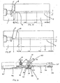
- Fig. 1 is a schematic cross-section along the central longitudinal axis of the downstream end of a first embodiment of needless syringe in accordance with the present invention.
- the gas source has been omitted.
- a possible gas source arrangement will be described later in conjunction with Figs. 3, 16 and 19 -22.
- the main body 1 of the syringe has a central aperture extending therethrough to form a lumen which bounds the gas flow path through the syringe, into the downstream end of which is fitted a nozzle 2.
- the bore 3 of the nozzle is substantially parallel-sided, apart from a short taper at its upstream end.
- a sonic nozzle 4 Fitted generally midway along the central aperture of the main body 1 is a sonic nozzle 4.
- This sonic nozzle 4 is provided with an aperture which forms a first convergence or constriction 5 to the flow of gas through the main body 1.
- the first convergence takes the form of two successive fairly abrupt constrictions 5a, 5b.
- the aperture of the first convergence is coaxial with the central longitudinal axis of the bore 3 of the nozzle 2.
- the portion of the sonic nozzle 4 forming the downstream end of the constriction 5b projects outwardly (in a downstream direction) from the flat main downstream face 6 of the sonic nozzle 4.
- the sonic nozzle 4 may be held in place within the central aperture of the main body 1 by cooperating screwthreads, or an interference fit in combination with a downstream shoulder formed by the main body 1.
- the flat, main downstream face 6 of the sonic nozzle 4 is spaced upstream from the upstream face 7 of nozzle 2.
- the upstream end of the nozzle 2 forms a second convergence or constriction 9 to the flow of gas through the main body 1. Again, in this embodiment, this convergence 9 is a fairly abrupt constriction.
- the nozzle 2 bounds the gas flow path, that is to say it surrounds and defines the space through which the gas may flow.
- the sonic nozzle constriction 5b has a significantly reduced flow cross-section relative to the flow cross-section of the particle entrainment chamber 8.
- the second convergence 9 has a much reduced flow cross-section relative to the flow cross-section of the chamber 8.
- the nozzle 2 is 50 mm in length
- the diameter of the sonic nozzle constriction 5b is 1 mm
- the diameter of the exit nozzle constriction 9 is 2.3 mm.
- the diameter of the particle entrainment chamber 8 is 5mm. Consequently, the flow cross-section of the second convergence 9 is approximately 5.3 times larger than the flow cross-section of the first convergence 5.
- the ratio of flow cross-sections between the first and second convergences 5, 9 is relevant to the functioning of the syringe.
- a particle inlet in the form of a particle inlet passage 10 is provided extending radially through the main body 1.
- the radially innermost end of the particle inlet passage 10 opens into the particle entrainment chamber 8 and the radially outer end of the passage 10 is arranged to communicate with a particle source 11 containing a payload of particles.
- the downstream tip of the sonic nozzle 4 defining the first convergence 5 is generally coincident with the central longitudinal axis of the particle inlet passage 10. It is thought that this relative positioning is relevant if, as is described below, particles are to be drawn into the particle entrainment chamber 8 as a result of the creation of a reduced (sub-atmospheric in this embodiment) pressure region within the chamber 8. If the particle inlet passage 10 is in communication with a portion of the particle entrainment chamber 8 that is at atmospheric pressure or higher, particles will not be drawn into the particle entrainment chamber 8 when the syringe is fired, assuming the particle source is at atmospheric pressure.
- the particle source 11 takes the form of a removable cassette having a central reservoir 12 in which the payload of particles (not shown) is deposited.
- a hole in the cassette provided at the base of the reservoir 12 lines up in communication with the particle inlet passage 10.
- the top of the reservoir 12 is open to atmosphere.
- a gas source is necessary to pressurize the central aperture of the main body 1 upstream of the sonic nozzle 4 (ie. to the left of the sonic nozzle 4 as drawn in Fig. 1).
- This gas source may take the form of a gas canister linked to a button cylinder (not shown), with operation of the button cylinder releasing a fixed amount of gas (for example 5 ml), enabling the gas source to be used to deliver sequentially a plurality of discrete payloads of particles without needing to be recharged.
- a closed gas cylinder containing a single dose of gas sufficient for a single needleless injection may be provided. This last arrangement is preferred as will be discussed below.
- the preferred gas for the gas source is helium, with the gas cylinder containing helium gas at a pressure of between 15 and 35 bar, preferably around 30 bar.
- the preferred driver gas is helium because it gives much higher gas velocity than air, nitrogen or CO 2 .
- the use of CO 2 as a source of driver gas is, however, superficially very attractive. Because, however, of the large variation of the saturation pressure of CO 2 with temperature, and the much lower velocities achievable therewith, the use of CO 2 may be limited.
- a single-shot button canister 61 comprising a plunger 64 and a sleeve body 62 defining a gas reservoir space 63 is shown attached to the Fig. 1 syringe in Fig. 3.
- a known volume of gas at a known pressure is suddenly released from the gas source (not shown) into the central aperture of the main body to the upstream side of the sonic nozzle 4.
- the initial pressure is sufficiently high so as to establish choked flow of the gas at the exit of the sonic nozzle 4, at its smallest constriction 5b.
- the transsonic gas jet which issues from the constriction 5b into the particle entrainment chamber 8 expands to create a reduced pressure region in the particle entrainment chamber 8, in a manner similar to the venturi effect.
- the reduced pressure region is sub-atmospheric in this embodiment.
- helium is preferably used as the driver gas.
- the gas issuing from the device is actually a mixture of helium and air, due to the air that is drawn in along with the particles via the particle inlet passage 10.
- the gas comprises about 15% air (by mass) at exit (the rest being helium).
- the relative sizes of the first and second convergences 5,9, as well as the longitudinal spacing therebetween, is such as to encourage the expanding, diverging gas jet to attach to the walls of the second convergence 9 and to remain attached to the walls of the nozzle 2 as the jet passes down the bore 3 of the nozzle 2.
- the radius of the chamber 8 is not thought to be particularly important although it should be large enough so that a free jet is capable of being formed in the chamber.
- the size of the target area impacted by the particles will be generally equal to the size of the bore 3 at the downstream exit of the nozzle 2 and the particles will be well distributed across the target area.
- a syringe similar to that illustrated in Figs. 1 and 2 was operated with a 5 ml button cylinder, (shown in Fig. 3) filled with air at a pressure of approximately 30 bar, and using a 1.0 to 1.5 mg payload of 55 ⁇ m lidocaine powder, the syringe was able to deliver the payload in such a way as to consistently anaesthetise a 2 to 3 mm diameter of the forearm within one minute. Given that the diameter of the nozzle bore 3 at the exit was 2.3 mm, the good spread of the particles across a target area substantially equal to the area of the nozzle bore 3 at the nozzle exit 2 will be appreciated.
- Performance comparisons (of which more later) between the different embodiments were made by discharging the embodiment of device, loaded with a known payload (between 1 mg and 3 mg) of 48 ⁇ m diameter polystyrene spheres above a 3 % agar gel target. Vented spacers were fitted to the end of the device nozzle so as to keep the devices at a fixed distance from the target surface and at right angles to it. After firing off the syringe the agar was then photographed to record the delivery footprint. The gel target was then sliced across its diameter and thin sections were photographed through a microscope to establish the depth of penetration of the individual particles.
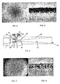
- Figs. 4 and 5 show the footprint and penetration near the center of the target of polystyrene spheres delivered from the first embodiment of device, at the conditions found to provide anaesthesia with lidocaine (ie. 3 ml cylinder filled with helium to 20 bar).
- the footprint diameter was 3 mm and the maximum depth of particle penetration was about 180 ⁇ m.
- Fig. 6 shows a second embodiment of a syringe in which the nozzle, instead of having a substantially parallel-sided bore, has a distinct divergence.
- Fig.6 components similar to components in Figs. I and 2 have been given the same reference numerals. The reference numerals associated with the nozzle have, however, been changed.
- the nozzle 15 comprises a short, upstream, parallel-sided section 16, leading into a long, divergent, downstream section 17.
- the diameter of the upstream parallel-sided section 16 is 2.3 mm.
- This section 16 forms the second convergence or constiiction 18 to gas flow.
- the diameter of the minimum area of the first convergence or constriction 5 is 1.0 mm, such that the area of the flow cross-section of the second convergence 18 is approximately 5.3 times the area of the flow cross-section of the first convergence 5.
- the length of the upstream parallel-sided section 16 of the bore of the nozzle 15 is 7 mm.
- the divergent downstream section 17 has a cone angle of approximately 8.8° and diverges to provide the bore of the nozzle 15 with a 10 mm exit diameter at the nozzle's downstream exit 19.
- the divergent section 17 is thought to allow the jet issuing from the sonic nozzle 4 to continue to expand supersonically before being broken down by a series of oblique shocks.
- Fig. 7 is top plan view of the agar target.
- Fig. 8 is a magnified cross-section of a diametral slice through the agar target, showing the penetration of the individual particles.
- Fig. 9 is a reconstruction of a diametral 10 mm wide slice through the agar target, showing the uniformity of distribution and penetration of the particles across the full width of the target.
- the good distribution of particles across a target area substantially equal to the size of the nozzle at the nozzle's downstream exit is influenced by the relative minimum sizes of the first and second convergences 5, 16, the distance by which they are spaced apart and the positioning of the particle inlet passage 10 relative to the exit of the first convergence and the entrance to the second convergence.
- the first embodiment of syringe appeared to be more effective over a small area of forearm than the second embodiment of syringe used with the same particle payload. Because, however, the particle penetration depth was similar in both cases a likely explanation for this is that insufficient lidocaine particles were being administered to the 10 nun diameter target area with the second embodiment of syringe.
- Fig. 10 and 11 show the effect of doubling the payload from 1 mg to 2 mg in the second embodiment. The penetration depth is slightly reduced to 160 ⁇ m (from 180 ⁇ m), but the particles are more densely packed.
- the second embodiment of syringe was also modified by extending its nozzle 15 in length. By maintaining the same taper angle of 8.8 degrees, the diameter of the nozzle at its downstream exit 19 was increased to 14 nun from 10 mm.
- This modified arrangement was tested with a 3 mg payload of lidacaine powder using a 5 ml cylinder of helium at 30 bar. The results are shown in Figs. 12 and 13. Although penetration depth has again fallen slightly (to 140 ⁇ m), the powder was still found to be substantially uniformly distributed over the full target area, the target area of course this time having a diameter of approximately 14 mm.
- the first and second embodiments described above utilize a first convergence or constriction 5 to create a reduced pressure region which is used to draw in a payload of particles.
- the first convergence or constriction as described comprises an upstream constriction 5a and a downstream constriction 5b. It is the smaller downstream constriction 5b that is choked during use.
- the third embodiment relates to a modification of this geometry which replaces the two-stage convergence of the first and second embodiments with a smoothly tapering convergence 5'. As shown in Fig. 14, the convergence 5' tapers down from a diameter of 6mm at the upstream end to a diameter of 1.2 mm at the downstream end over a length of about 17mm.
- high pressure gas presented to the upstream end of the convergence will tend to have its pressure reduced as it flows along the gas flow path through the convergence 5' and into the chamber 8. This reduced pressure can then be used to draw in a payload of particles from the particle source 11 (not shown in Fig. 14).
- the chamber 8 is the preferred position for the particle inlet passage 10 (not shown in Fig. 14) and it has been found that the transsonic gas jet formed effectively entrains the particles such that they are uniformly distributed in the gas flow.
- the particles are introduced in this chamber and in fact they may be introduced at any position in the device where there is a reduced pressure region in the gas flow path. Since the reduced pressure stems from the Venturi effect caused by the first convergence 5', the device is still effective when the particles are introduced upstream of the chamber 8, in the first convergence 5'. It is enough that the gas flow path has started to converge at the position where the particle inlet passage 10 is located such that there is a reduction in pressure sufficient to draw in the particles.
- the particle inlet passage 10 may be located downstream of the chamber 8 either at the second convergence 9 or downstream thereof in the nozzle bore 3. It has been found that the gas pressure in these positions is reduced to a value sufficient to cause the drawing in effect of the particles.
- the third embodiment works in a very similar way to the first and second embodiments in so far as there is provided a first convergence or constriction followed by a chamber of increased cross-section followed by another convergence or constriction.
- the chamber of increased cross-section is thought to provide a discontinuity to the gas flow which leads to the creation within the chamber of a transsonic jet, which jet passes through the chamber and attaches to the walls of the nozzle bore 3 in the region of the second convergence 9.
- a normal shock wave is thought to be formed across the second convergence which increases the pressure and reduces the velocity of the gas.
- the nozzle portion then serves to accelerate the particles in the already quickly moving gas stream.
- the first and third embodiments (with a parallel sided nozzle bore 3) are thought to have particular application in dentistry where it is useful to achieve penetration of a small target area and where the mucosal surfaces are relatively easy to penetrate.
- the mass flow rate of gas through the device is determined by the driver pressure and the smallest cross sectional flow area in the device. This smallest area is preferably the first convergence 5, 5'. Thus, it is expected that the first convergence will be choked during normal operation.
- Fig. 15 shows a fourth embodiment of needleless syringe in accordance with the present invention in which the chamber 8 has been replaced by a divergent section 60.
- the first convergence or constriction 5' is shown as having a tapered form similar to that in Fig. 14, although the two-stage first convergence 5a, 5b of the embodiments of Figs. 1 and 2 would also be acceptable.
- this embodiment because there is no chamber 8, there is no second convergence as such and the gas flow path diverges from the point of minimum cross-section of the first convergence 5' to the cross-section of the nozzle bore 3.
- This change in geometry means that no transsonic jet is formed and instead the configuration acts like a convergent-divergent nozzle which accelerates the flow to supersonic speeds (with low static pressures).
- the particle payload can be introduced at any point in the gas flow where the pressure is low enough to cause the drawing-in effect to take place. In practice this is a position between a point in the convergence 5' where the pressure has reduced enough to a point in the nozzle bore 3 far enough upstream to give the particles adequate residence time in the nozzle to achieve the desired velocity.
- the particle inlet passage 10 may be positioned anywhere in the divergent section 60.
- the gas source is not shown.
- the gas source may advantageously take the form of a single shot gas canister, preferably a helium gas canister.
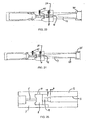
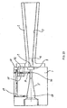
- Fig. 16 shows a fifth embodiment of a syringe in accordance with the present invention.
- the main body 30 is provided with a nozzle 31 having an upstream parallel-sided section 32, a short divergent section 33 downstream thereof, followed by a long downstream generally conical section 34.
- a spacer 35 Provided on the downstream end of the nozzle 31 is a spacer 35, whose downstream face is intended to be placed against the skin or mucosa surrounding the target area to space the nozzle's downstream exit face 36 from the target area.
- the spacer 35 is provided with a plurality of radial outlets to allow the escape of the driver gas.
- the particle source 37 takes the form of a cassette having a reservoir 38 provided therein to receive the payload of particles.
- This reservoir 38 is in communication with the particle entrainment chamber 39 via the particle inlet passage 40.
- a sonic nozzle 41 Provided at the upstream end of the particle entrainment chamber 39 is a sonic nozzle 41, whose central aperture forms the first convergence or constriction 42 to the flow of gas from the gas source.
- the second convergence or constriction 43 is provided by the upstream end of the upstream parallel-sided section 32 of the bore of the nozzle 31.
- the minimum diameters of the first and second convergences shown are 1mm and 2.3mm respectively.
- the gas source is positioned to the left (as drawn) of the main body 30.
- the gas source includes a gas cylinder 44 received within a housing 45.
- the right-hand end (as drawn) of the gas cylinder 44 is provided with a longitudinally extending nose 49, which nose is capable of being fractured, so as to allow the escape of gas from the interior of the cylinder 44, upon the application of lateral pressure to the nose 45 in the direction identified by the arrow referenced 46.
- this lateral pressure is applied by moving a plunger 47 radially inwardly, using the pressure from a thumb or finger, sufficiently far as to fracture the nose 49 and to cause gas release from the cylinder 44. It is this release of gas which pressurizes the space upstream of the sonic nozzle 41, leading to choked flow of the released gas through the first convergence 42.
- the gas cylinder 44 need not have its nose pointed to the right (as drawn). It may, for example, be turned through 180° so that its nose points to the left.
- a thin gauze filter 48 may, as shown, be provided between the gas cylinder 44 and the sonic nozzle 41 so as to filter the gas from the cylinder prior to its passage through the sonic nozzle 41.
- the method and mechanism of operation of the fifth embodiment is similar to that of the first to fourth embodiments and will not be further described here.
- the relationship between the area of the first and second convergences (or the relationship between the area of the first convergence and the area of the nozzle in the fourth embodiment) is thought to be significant.
- Diameters of 1.0 and 2.3 mm for the first and second convergences respectively, equating to a flow cross-sectional area ratio of 1:5.3 worked well.
- Other constructions that worked well were diameters of 1.2 and 3.0 mm for the first and second convergences, 1.3 and 3mm for the first and second convergences and 1.4 and 3.5mm for the first and second convergences respectively, equating to flow cross-sectional area ratios of 1:6.25, 1:5.3 and 1:6.25 respectively.
- diameters of 1.2 and 2.3 for the first and second convergences respectively, equating to a ratio of 1:3.7 did not work well.
- a larger mass flow rate can be established and a more powerful device can be constructed. Pressures of up to 60 bar may be used as a driver, in order to provide enough propellent to support the increased mass flow rate.
- the particle source 11 whilst suitable for use in the laboratory, would not be particularly well suited to commercial use because the powder to be delivered could become contaminated and / or fall out of the reservoir provided in the particle source cassette.
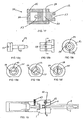
- Fig. 17 shows one possible way of sealing a metered quantity of powder in a sealed container until it is ready for use.
- the particle source 50 has a two-piece construction, comprising a cassette body 51 and a rotatable and axially slidable plug 52.
- the cassette body 51 has three radial holes 53, 54 provided therein.
- Hole 54 is a single filling hole to enable the powder cavity 55 in the plug 52 to be filled with a metered dose of powder.
- a pair of diametrically opposed holes 53 are also provided, of which only one is visible in Fig. 12.
- One of these holes 53 is a powder exit hole.
- Fig. 14 shows the plug 52 in a position enabling the powder cavity 55 provided therein to be filled through the filling hole 54. After filling, the plug 52 is slid to the left (as drawn) to position the powder cavity 55 in the same plane as holes 53, but not to align it with either of holes 53.
- the cassette 50 can then be mounted on the syringe with one or other of its radial throughholes 53 aligned with the syringe's particle inlet passage leading to the particle entrainment chamber 8.
- a tool for example a screwdriver type blade, can be inserted into a slot 57 provided in the right-hand end (as drawn) of the plug, enabling the plug to be rotated through 90° within the cassette body 51 to bring the powder cavity 55 into alignment with both of the diametrically opposed holes 53.
- Figs. 18a to 18f show a second way of sealing a metered quantity of powder in a sealed container until it is ready for use.
- the same reference numerals as Fig. 17 are used where possible.
- Fig 18a shows a plug member 52
- Figs. 18b and 18c show orthogonal views of a cassette body 50
- Figs. 18d to 18f show the plug member 52 inserted into the cassette body 50 in various orientations.
- the cassette body 50 has three radial holes 53, 54 provided therein, a single filling hole 54, to enable the powder cavity 55 in the plug 52 to be filled with a metered dose of powder and a pair of diametrically opposed holes 53 which are used when the plug 52 is in the operating position (Fig. 18f).
- the plug 52 is rotatable in the cassette body but, contrary to the Fig. 17 embodiment, is not meant to be actively slidable in use.
- the plug 52 is aligned with filling hole 54 so that particles can be placed in the powder cavity 55 via hole 54 (see Fig. 18d).
- the plug 52 is then rotated (again by using a screwdriver in slot 57 or other means for turning, e.g. using a spanner or manually operating a lever built into the plug 52) by approximately 45° such that, although the powder cavity 55 is in the same plane as all three of the holes 53,54, it is not in communication with any of them (see Fig. 18e).
- This storage position ensures that the powder cannot escape.
- the plug 52 is rotated by a further 45° so that the particles come into fluid communication with each of the diametrically opposed holes 53 (see Fig. 18f).
- this embodiment does not require the additional step of actively sliding the plug 52.
- Fig. 19 shows the cassette body 50 and plug 52 mounted on a needleless syringe similar to that shown in Fig. 1.
- the cassette body 50 can be made integral with the syringe main body 1 so that the holes 53 are aligned with the particle inlet passage 10 and the atmosphere respectively.
- FIGs. 1 and 19 show an exit nozzle 2 having a substantially parallel sided bore 3. This can be used to deliver particles to a relatively small target area, and due to the localized delivery has been found to be particularly effective in dental applications for example in anesthesia.
- Fig.s 6 and 20 show an exit nozzle 2 having a relatively short parallel section 16 followed by a divergent section 17. This has been found to effectively increase the target area of particle penetration, although there seems to be a limit as to how much the exit nozzle can diverge before boundary layer separation takes place and the jet forms a "core" of particles which is smaller than the exit diameter of the nozzle.
- a short parallel section 16 is followed by a divergent section 17 which in turn is followed by a parallel section 65.
- the downstream parallel section 65 following the divergent section 17 helps to reattach the boundary layer which can become separated in the divergent section 17 and yields a more uniform particle distribution across the whole exit diameter of the nozzle.
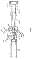
- Fig. 22 shows a sixth embodiment of the invention which combines many of the features of the previously described embodiments but also has a novel actuating mechanism which serves to align the powder cassette plug 52 into the operating position and actuates the cylinder fracturing mechanism in one simple operation.
- an actuating lever 66 is provided which rotates about the same pivot axis 67 as the plug 52 of the powder cassette. Initially, the actuating lever 66 is provided in a primed position in which the powder cavity 55 is oriented at 45° from the position in which it is aligned with the particle inlet passage 10. This is the previously described "storage" position.
- the actuating lever 66 can be pressed by the thumb of an operator and in so doing rotates about its pivot axis 67 to bring the powder cavity 55 almost into alignment with the diametrically opposed holes and thus bring the powder into fluid communication with the gas flow path (via the particle inlet passage 10).
- This position of actuating lever is also shown in Fig. 22 and is denoted by 66'.
- the lever 66 In the final stages of pressing the actuating lever 66, the lever 66 abuts the actuating pin 47 and further pressure causes the frangible tip 49 of the gas cylinder 44 to fracture and thereby triggers the device (Fig. 22 shows the frangible tip 49 in both an unbroken and broken position).
- the lever 66 typically turns 40° before it abuts the actuating pin 47 and the final 5° is used to fracture the cannister tip and bring the powder cavity 55 into full alignment.
- a mechanism is provided whereby the powder can be moved from the storage position to the operating position and the device can be triggered in one easy movement.
- Fig. 22 is shown with the nozzle of Fig. 21 (parallel-divergent-parallel nozzle). However, any of the heretofore described nozzle designs maybe utilized, either with or without a spacer 35.
- the above embodiments all utilize a first convergence 5, 5' to create a reduced pressure region which can be used to draw the particles into the gas flow path.
- the reduced pressure since the particles are initially provided in contact with the atmosphere, the reduced pressure must necessarily be sub-atmospheric for the effect to work properly.
- the seventh embodiment relates to a construction in which the particles are provided in fluid communication with an upstream portion of the gas flow path such that, in use, the reduced pressure need not be sub-atmospheric and need only be reduced compared to the pressure at that upstream portion of the flow path.
- Fig. 23 schematically illustrates the concept on a device having a similar construction to that shown in Fig. 14, but with a divergent nozzle.
- the powder cassette 50 is rotated 90° about a vertical axis as compared with the orientation shown in Fig.s 19 to 22, and the top hole 53 of the powder cassette 50, instead of being vented to atmosphere, is provided in fluid communication with an upstream part 68 of the gas flow path, upstream of the first convergence 5'. This fluid communication is achieved by passage 69.
- the particle inlet passage 10 fluidly communicates with the other hole 53 of the particle cassette 50 and a more downstream part 70 of the convergence 51.
- the convergence 5' causes a reduction in gas pressure, in use, due to the Venturi effect such that there is, in use, a pressure differential across the powder cavity 55.
- the particles are still drawn into the gas flow path because the pressure is at least reduced compared to the pressure to which the particles are exposed (i.e. that pressure present at the upstream end 68 of the device).
- the amount of gas which flows along the passage 69 is preferably small compared to the flow rate along the gas flow path, e.g. 20% or so.
- gas pressure close to the driver pressure can be used to inject the particles into the gas flow.
- the particle inlet passage 10 and passage 69 are positioned so that about 0.2 times the driver pressure is present across the particles in use. When 30 bar driver pressure is used, this corresponds to a pressure difference of 6 bar which serves to draw the particles into the flow.
- this pressure difference By modifying this pressure difference, the time at which the particles are drawn into the flow can be controlled. This timing can also be controlled by modifying the length and/or tortuousness of the passage 69.
- this embodiment provides a form of particle "injection” and gives greater flexibility as to where the particles can be introduced since the requirement for sub-atmospheric pressure is dispensed with.
- the particles are shown being injected into the first convergence 5', they may be injected into the chamber 8, the second convergence 9, the nozzle bore 3, 16, 17 or the divergent section 60 as described in relation to the other embodiments.
- This embodiment has the further advantage that no atmospheric air is induced into the gas flow meaning that the device is self-contained in use. This reduces the possibility of contamination of the particles by contaminants suspended in atmospheric air.
- a large divergent portion 17 of the exit nozzle 2 can cause "coring" whereby the boundary layer separates from the nozzle walls and the majority of the jet power is concentrated along a central longitudinal axis such that the particles are not evenly distributed across the full area of the nozzle at the nozzle exit plane.
- This can be ameliorated by the use of a second parallel section 65 (see Fig. 21) and it is thought the parallel section 65 encourages re-attachment of the boundary layer in the nozzle.
- the eighth embodiment provides a further modifcation to the divergent section 17 of the exit nozzle which can ameliorate this effect.
- Fig. 24 schematically shows the principle as applied to the embodiment of Fig. 14, but with a divergent nozzle.
- a return gas flow path 71 is provided between a point 72 in the divergent nozzle and a point 73 upstream of that point 72.
- the Venturi effect means that the position 73 of lower cross-sectional area will have a reduced pressure as compared to the position 72 of higher cross-sectional area. This will cause gas flow to be routed from the downstream point 72 to the upstream point 73 due to the pressure differential in use.
- This embodiment can therefore be utilized to provide a more even spread of particles and less "coring" of the gas stream.
- This embodiment utilizes a further nozzle geometry which is similar to the geometry shown in Fig. 21 except that the divergence extends over a very short length longitudinally, as shown in Fig. 25.
- the divergence typically covers a longitudinal length "A" of only one quarter to one eighth of the diameter of the second convergence 9 and this nozzle geometry is referred to as a "fast expand” nozzle.
- the idea behind it is that the gas should be expanded as quickly as possible so as to ensure that particles are accelerated by the fast moving gas stream for the longest time period possible. This is thought to provide a higher particle speed.
- the "fast expand” nozzle may be used to replace the nozzle of any of the previously described embodiments.
- the device shown in Fig. 20 having a 10 mm nozzle exit diameter has been tested with different volumes (3 and 5 ml) and driver pressures (20 to 60 bar).
- low driving pressures (5 ml at 25 bar) give very uniform distribution of the particles on the target but with relatively low penetrations (160 to 180 ⁇ m) of 47 ⁇ m diameter polystyrene beads into a 3% agar gel target.
- penetration increases but the particle distribution becomes more skewed to that side of the target which is opposite the position of powder entry via the particle inlet passage 10.
- Further increase of the gas pressure causes the pressure in the chamber 8 to rise above that of the atmosphere which results in the particles being ejected from the air aspiration hole. This problem was overcome by increasing the diameter of the upstream parallel exit nozzle section to accommodate the higher gas flow rates.
- Mass flow rates were also increased by using larger diameter sonic throats.
- this embodiment which utilizes the outside atmospheric pressure to draw in the particle payload, it is necessary to ensure that the sonic throat and parallel section of the diameters are matched, to prevent a blow-back of particles.
- the alignment of the sonic throat exit plane and the particle inlet passage 10 in the chamber 8 is also important in preventing the particle blow-back.
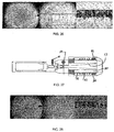
- a 10 mm diameter exit plane device fitted with a 1.2 mm diameter sonic throat and a 3 mm diameter upstream exit nozzle parallel section and using a 5 ml, 40 bar helium cannister gave the footprint and penetration results shown in Fig. 26.
- the payload was 1 mg of 48 ⁇ m of polystyrene beads.
- the left hand image shows the footprint (approximately 11 mm diameter) of the particles and a 3% agar gel target: there is an increased concentration of particles near the centre of the footprint, but the asymmetry of the distribution is not so noticeable in this image.
- the middle image shows the distribution of particles across a diametral slice of the target and the left hand image shows an enlarged view of particle penetration at the center of the slice, from which a maximum penetration of 250 ⁇ m can be measured.
- a simple silencer device (shown in Fig. 27) was fitted to the Fig. 20 embodiment.
- the silencer consists of a first passage 80 which the gas upon which rebounding from the target plane passes along.
- This passage 80 is aligned in an annulus around the exit nozzle 17.
- the gas then passes through a port 81 before being passed across a series of radially extending baffles 82. It is thought the baffles serve to breakdown the gas pressure into a series of shock waves.
- the gas passes through a mesh filter 83 and out through an exit port 84.
- Use of the silencer produces a back pressure which has two effects. The first effect is to generate a "lift-off" force which tends to separate the device from the target plane and the second effect is to reduce the performance of the device, since the gas is now expanded to a nozzle exit pressure above atmospheric.
- the lift-off force of the silenced device was measured by operating it against a flat plate loaded with different masses, a displacement transducer indicating when the sealing force was insufficient to maintain contact.
- This method gave lift-off forces of the order of 5 N, which is considerably lower than the Fig. obtained by assuming that the peak pressure maintained on the plate generates the maximum lift-off force (13 N),
- Fig. 28 shows the same data for the silenced device as that displayed in Fig. 26 for the unsilenced device. The main difference is that the maximum penetration has been reduced to 225 ⁇ m.
- the device shown in Fig. 21 was also tested. This device also has a 1,0 mm diameter exit plane and the downstream parallel extension 65 is 30 mm long.
- Fig. 29 shows the improved footprint achieved when this device was operated at conditions corresponding to those of Fig. 26.
- the particles are more uniformly dispersed over the target and the maximum penetration is still 250 ⁇ m.
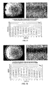
- the sonic throat was increased to 1.3 mm and used with a 50 bar, 5 ml helium cylinder.
- the footprint and mean penetrations are shown in Fig. 30.
- the particles are fairly asymmetrically distributed on the target and that the distribution of penetration depths is large - ranging from 60 ⁇ m at the edges to 120 ⁇ m near the center.
- the most powerful version of the Fig. 20 device tested had a 2.4 mm diameter sonic throat, a 3.5 mm diameter upstream exit nozzle section and used a 60 bar, 5 ml helium cannister. When used with a payload of 1 mg of polystyrene spheres, it produced a crater in the centre of the 3% agar gel target. With the 30 mm parallel extension (Fig. 21) there was comparatively little damage to the target.
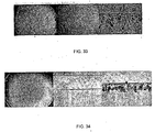
- An example of the performance of the device is shown in Fig. 33 where the target is a 3% agar gel and the payload was 1 mg of 50 ⁇ m agarose beads (A-121). These particles have a lower density than either polystyrene or lidocaine and consequently they do not penetrate as deeply for a given velocity. Nevertheless, the maximum penetration measured was 280 ⁇ m.
- Fig. 34 shows the results when the device of Fig. 20 was used with a 1 mg payload of particles and a driver pressure of 25 bar. As can be seen, a maximum penetration of 120 ⁇ m and a footprint of about 11 mm diameter was obtained.
- Such filters may be advantageous to provide a high efficiency particle air filter so as to remove any potential source of contamination from air drawn into the syringe through the cassette of the particle source.
- Such filters are commercially available and have low pressure drops.
- Such filters have an upper limit to gas velocity through the filter so as to ensure that they operate to the specification.
- the surface area of such a filter could clearly be chosen to match the gas velocity therethrough that will be encountered in use.
- An alternative to an air filter would be to bleed a supply of driver gas at, or near, atmospheric pressure to the particle cassette inlet As described above with relation to the seventh embodiment, however, the gas bled to the particle inlet may be substantially higher than atmospheric.
- Any of the already described nozzles maybe contoured, for example, using the method of characteristics, to provide a reduction in the number of oblique shock waves that form in the nozzle during use.
- Profiling the nozzle in this way is also thought to improve the particle distribution at the exit plane.
- the major components of the needleless syringe may for example be made of metal or of engineering plastics materials. The latter materials are preferred because they may readily be molded and are light in weight.
- the device of all embodiments of the present invention is designed to be quieter in operation than the device of US 5,630,796 (which uses a rupturable membrane), some noise is still detected and a silencing device, perhaps comprising a plurality of baffles and a mesh filter can be used to further reduce the noise experienced.
Landscapes
- Health & Medical Sciences (AREA)
- Engineering & Computer Science (AREA)
- Hematology (AREA)
- Life Sciences & Earth Sciences (AREA)
- Vascular Medicine (AREA)
- Anesthesiology (AREA)
- Biomedical Technology (AREA)
- Heart & Thoracic Surgery (AREA)
- Bioinformatics & Cheminformatics (AREA)
- Pharmacology & Pharmacy (AREA)
- Animal Behavior & Ethology (AREA)
- General Health & Medical Sciences (AREA)
- Public Health (AREA)
- Veterinary Medicine (AREA)
- Infusion, Injection, And Reservoir Apparatuses (AREA)
- Apparatus Associated With Microorganisms And Enzymes (AREA)
- Saccharide Compounds (AREA)
- Analysing Materials By The Use Of Radiation (AREA)
Applications Claiming Priority (3)
| Application Number | Priority Date | Filing Date | Title |
|---|---|---|---|
| GBGB0100756.6A GB0100756D0 (en) | 2001-01-11 | 2001-01-11 | Needleless syringe |
| GB0100756 | 2001-01-11 | ||
| PCT/GB2002/000114 WO2002055139A1 (en) | 2001-01-11 | 2002-01-11 | Needleless syringe |
Publications (2)
| Publication Number | Publication Date |
|---|---|
| EP1365824A1 EP1365824A1 (en) | 2003-12-03 |
| EP1365824B1 true EP1365824B1 (en) | 2006-03-22 |
Family
ID=9906669
Family Applications (1)
| Application Number | Title | Priority Date | Filing Date |
|---|---|---|---|
| EP02729462A Expired - Lifetime EP1365824B1 (en) | 2001-01-11 | 2002-01-11 | Needleless syringe |
Country Status (14)
| Country | Link |
|---|---|
| US (2) | USRE43824E1 (https=) |
| EP (1) | EP1365824B1 (https=) |
| JP (2) | JP2004521677A (https=) |
| AT (1) | ATE320827T1 (https=) |
| AU (1) | AU2002219368B2 (https=) |
| CA (1) | CA2433992A1 (https=) |
| CY (1) | CY1106102T1 (https=) |
| DE (1) | DE60210063T2 (https=) |
| DK (1) | DK1365824T3 (https=) |
| ES (1) | ES2260433T3 (https=) |
| GB (1) | GB0100756D0 (https=) |
| NZ (1) | NZ527298A (https=) |
| PT (1) | PT1365824E (https=) |
| WO (1) | WO2002055139A1 (https=) |
Cited By (6)
| Publication number | Priority date | Publication date | Assignee | Title |
|---|---|---|---|---|
| CN100446823C (zh) * | 2006-09-19 | 2008-12-31 | 宁波新芝生物科技股份有限公司 | 一种无创介入治疗系统 |
| US7998106B2 (en) | 2004-05-03 | 2011-08-16 | Thorne Jr Gale H | Safety dispensing system for hazardous substances |
| US12226568B2 (en) | 2020-06-05 | 2025-02-18 | Cook Medical Technologies Llc | Medical scopes for delivering therapeutic agents |
| US12318573B2 (en) | 2013-10-02 | 2025-06-03 | Cook Medical Technologies Llc | Therapeutic agents for delivery using a catheter and pressure source |
| US12496429B2 (en) | 2022-10-18 | 2025-12-16 | Cook Medical Technologies Llc | Systems and methods for delivering pressurized fluid to a target site alone or in conjunction with therapeutic agents |
| US12543936B2 (en) | 2021-07-14 | 2026-02-10 | Cook Medical Technologies Llc | Systems and methods for preventing clogging of a delivery system |
Families Citing this family (70)
| Publication number | Priority date | Publication date | Assignee | Title |
|---|---|---|---|---|
| CA2324045A1 (fr) * | 2000-10-20 | 2002-04-20 | Universite De Sherbrooke | Seringue sans aiguille pour l'injection sous-cutanee de poudres medicamenteuses |
| GB0100756D0 (en) | 2001-01-11 | 2001-02-21 | Powderject Res Ltd | Needleless syringe |
| US8061006B2 (en) | 2001-07-26 | 2011-11-22 | Powderject Research Limited | Particle cassette, method and kit therefor |
| GB0300008D0 (en) * | 2003-01-02 | 2003-02-05 | Optinose As | Delivery devices |
| USD519633S1 (en) | 2003-11-12 | 2006-04-25 | Powderject Research Limited | Syringe |
| KR101225216B1 (ko) | 2004-12-01 | 2013-01-22 | 아큐샷 인크. | 무침 주사기 |
| WO2007061896A1 (en) * | 2005-11-17 | 2007-05-31 | Zogenix, Inc. | Delivery of viscous formulations by needle-free injection |
| EP1954336A4 (en) * | 2005-11-29 | 2012-05-09 | Biodesign Res & Dev | ELECTROSTATIC, TRANSCUTANEOUS HYPODERMIC SPRAY (ELECTROSTATIC HYPOSPRAY) |
| US8020726B1 (en) * | 2006-10-18 | 2011-09-20 | Sandia Corporation | Powder dispersion system |
| GB0708758D0 (en) | 2007-05-04 | 2007-06-13 | Powderject Res Ltd | Particle cassettes and process thereof |
| US20090062233A1 (en) | 2007-08-09 | 2009-03-05 | Xin Ji | Modified starch material of biocompatible hemostasis |
| AU2009244462B2 (en) | 2008-05-06 | 2013-04-11 | Cook Medical Technologies Llc | Apparatus and methods for delivering therapeutic agents |
| US8788212B2 (en) | 2008-10-31 | 2014-07-22 | The Invention Science Fund I, Llc | Compositions and methods for biological remodeling with frozen particle compositions |
| US8551505B2 (en) | 2008-10-31 | 2013-10-08 | The Invention Science Fund I, Llc | Compositions and methods for therapeutic delivery with frozen particles |
| US9050251B2 (en) | 2008-10-31 | 2015-06-09 | The Invention Science Fund I, Llc | Compositions and methods for delivery of frozen particle adhesives |
| US9072799B2 (en) | 2008-10-31 | 2015-07-07 | The Invention Science Fund I, Llc | Compositions and methods for surface abrasion with frozen particles |
| US8545855B2 (en) | 2008-10-31 | 2013-10-01 | The Invention Science Fund I, Llc | Compositions and methods for surface abrasion with frozen particles |
| US20100111857A1 (en) | 2008-10-31 | 2010-05-06 | Boyden Edward S | Compositions and methods for surface abrasion with frozen particles |
| US8545857B2 (en) | 2008-10-31 | 2013-10-01 | The Invention Science Fund I, Llc | Compositions and methods for administering compartmentalized frozen particles |
| US8798932B2 (en) | 2008-10-31 | 2014-08-05 | The Invention Science Fund I, Llc | Frozen compositions and methods for piercing a substrate |
| US9060934B2 (en) | 2008-10-31 | 2015-06-23 | The Invention Science Fund I, Llc | Compositions and methods for surface abrasion with frozen particles |
| US8603494B2 (en) | 2008-10-31 | 2013-12-10 | The Invention Science Fund I, Llc | Compositions and methods for administering compartmentalized frozen particles |
| US9060926B2 (en) | 2008-10-31 | 2015-06-23 | The Invention Science Fund I, Llc | Compositions and methods for therapeutic delivery with frozen particles |
| US8725420B2 (en) | 2008-10-31 | 2014-05-13 | The Invention Science Fund I, Llc | Compositions and methods for surface abrasion with frozen particles |
| US8603495B2 (en) | 2008-10-31 | 2013-12-10 | The Invention Science Fund I, Llc | Compositions and methods for biological remodeling with frozen particle compositions |
| US8721583B2 (en) | 2008-10-31 | 2014-05-13 | The Invention Science Fund I, Llc | Compositions and methods for surface abrasion with frozen particles |
| US8409376B2 (en) | 2008-10-31 | 2013-04-02 | The Invention Science Fund I, Llc | Compositions and methods for surface abrasion with frozen particles |
| US9050070B2 (en) | 2008-10-31 | 2015-06-09 | The Invention Science Fund I, Llc | Compositions and methods for surface abrasion with frozen particles |
| US9050317B2 (en) | 2008-10-31 | 2015-06-09 | The Invention Science Fund I, Llc | Compositions and methods for therapeutic delivery with frozen particles |
| US8788211B2 (en) | 2008-10-31 | 2014-07-22 | The Invention Science Fund I, Llc | Method and system for comparing tissue ablation or abrasion data to data related to administration of a frozen particle composition |
| US9060931B2 (en) | 2008-10-31 | 2015-06-23 | The Invention Science Fund I, Llc | Compositions and methods for delivery of frozen particle adhesives |
| US8485861B2 (en) | 2008-10-31 | 2013-07-16 | The Invention Science Fund I, Llc | Systems, devices, and methods for making or administering frozen particles |
| US8793075B2 (en) * | 2008-10-31 | 2014-07-29 | The Invention Science Fund I, Llc | Compositions and methods for therapeutic delivery with frozen particles |
| US8731841B2 (en) | 2008-10-31 | 2014-05-20 | The Invention Science Fund I, Llc | Compositions and methods for therapeutic delivery with frozen particles |
| US8731840B2 (en) | 2008-10-31 | 2014-05-20 | The Invention Science Fund I, Llc | Compositions and methods for therapeutic delivery with frozen particles |
| US9072688B2 (en) | 2008-10-31 | 2015-07-07 | The Invention Science Fund I, Llc | Compositions and methods for therapeutic delivery with frozen particles |
| US8762067B2 (en) | 2008-10-31 | 2014-06-24 | The Invention Science Fund I, Llc | Methods and systems for ablation or abrasion with frozen particles and comparing tissue surface ablation or abrasion data to clinical outcome data |
| EP2453831B1 (en) * | 2009-07-14 | 2013-08-14 | Koninklijke Philips Electronics N.V. | Atomized liquid oral cleaning appliance |
| CN102019028B (zh) * | 2009-09-17 | 2013-09-11 | 纪欣 | 体内干粉输送装置 |
| US8439896B2 (en) * | 2009-11-13 | 2013-05-14 | The Invention Science Fund I, Llc | Device, system, and method for targeted delivery of anti-inflammatory medicaments to a mammalian subject |
| US8894630B2 (en) | 2009-11-13 | 2014-11-25 | The Invention Science Fund I, Llc | Device, system, and method for targeted delivery of anti-inflammatory medicaments to a mammalian subject |
| US8784368B2 (en) * | 2009-11-13 | 2014-07-22 | The Invention Science Fund I, Llc | Device, system, and method for targeted delivery of anti-inflammatory medicaments to a mammalian subject |
| TWI400103B (zh) * | 2009-12-03 | 2013-07-01 | Leader Machine Co Ltd | Drug delivery device |
| EP3403682A1 (en) * | 2010-10-07 | 2018-11-21 | Massachusetts Institute Of Technology | Delivery of a solid body and/or a fluid using a linear lorentz-force actuated needle-free jet injection system |
| GB201021881D0 (en) * | 2010-12-23 | 2011-02-02 | Profibrix Bv | Powder delivery device |
| US8388569B2 (en) | 2011-04-19 | 2013-03-05 | Xerox Corporation | Delivery devices and methods with collimated gas stream and particle source |
| US8430839B2 (en) | 2011-04-19 | 2013-04-30 | Palo Alto Research Center Incorporated | Drug delivery devices and methods with collimated gas stream and drug reservoir |
| US8486002B2 (en) * | 2011-04-19 | 2013-07-16 | Palo Alto Research Center Incorporated | Drug delivery devices and methods with collimated gas stream and release-activatable tape |
| EP2793731A1 (en) * | 2011-12-23 | 2014-10-29 | Koninklijke Philips N.V. | Device for delivery of a tooth whitening agent |
| WO2014062057A1 (en) * | 2012-10-15 | 2014-04-24 | Inflotek B.V. | Nozzle for fine-kerf cutting in an abrasive jet cutting system |
| US9618263B2 (en) | 2012-12-14 | 2017-04-11 | Flash Rockwell Technologies, Llc | Non-thermal drying systems with vacuum throttle flash generators and processing vessels |
| US8920364B2 (en) | 2013-02-28 | 2014-12-30 | Medtronic Xomed, Inc. | Biomaterial delivery device |
| USD708737S1 (en) | 2013-02-28 | 2014-07-08 | Medtronic Xomed, Inc. | Biomaterial dispensing device |
| USD708738S1 (en) | 2013-02-28 | 2014-07-08 | Medtronix Xomed, Inc. | Biomaterial delivery device |
| US10279113B2 (en) * | 2013-05-17 | 2019-05-07 | Socpra Sciences Et Genie S.E.C. | Needleless syringe and method for delivering therapeutic particles |
| KR101502752B1 (ko) | 2014-01-29 | 2015-03-16 | 조민수 | 가스압축식 무침주사기 |
| CN106163500A (zh) | 2014-02-26 | 2016-11-23 | 普乐药业有限公司 | 用于递送颗粒的装置 |
| JP2016049246A (ja) | 2014-08-29 | 2016-04-11 | 株式会社ダイセル | 無針注射器 |
| CN105412975B (zh) | 2014-09-18 | 2019-05-31 | 苏州安德佳生物科技有限公司 | 一种生物相容性止血制品及其制备方法 |
| JP6438848B2 (ja) * | 2015-06-09 | 2018-12-19 | 株式会社スギノマシン | ノズル |
| CN108498879B (zh) | 2017-02-28 | 2021-12-28 | 苏州安德佳生物科技有限公司 | 黏膜下注射用组合物和试剂组合及其应用 |
| CA3063324A1 (en) | 2017-05-16 | 2018-11-22 | Bhami's Research Laboratory, Pvt. Ltd. | High concentration protein formulations with reduced viscosity |
| US10239185B2 (en) | 2017-08-23 | 2019-03-26 | Aeroetch Holdings, Inc. | Self-powered pressurized granular particle ejector tool with remote operation |
| CN110025821A (zh) | 2018-01-12 | 2019-07-19 | 北京环球利康科技有限公司 | 使用生物相容性止血剂和组织封闭剂的组合物处理活动性出血的方法 |
| FR3082711A1 (fr) * | 2018-06-26 | 2019-12-27 | L'oreal | Systeme d’injection sans aiguille |
| DE102019113431B4 (de) | 2018-06-28 | 2024-08-22 | Bundesdruckerei Gmbh | Verfahren und Vorrichtung zur Kennzeichnung einer Datenseite, insbesondere für ein Wert- und/oder Sicherheitsdokument |
| DE102018128273A1 (de) * | 2018-11-12 | 2020-05-14 | Alina Predescu-Melzer | Nadelfreies Injektionsgerät zur nadelfreien Injektion einer wirkstoffhaltigen Lösung |
| US11717656B2 (en) | 2019-03-20 | 2023-08-08 | Gyros ACMI Inc. | Delivery of mixed phase media for the treatment of the anatomy |
| US12434350B2 (en) | 2021-03-08 | 2025-10-07 | Aeroetch Holdings, Inc. | Atmospheric pressure venturi intermix regulator cartridge and emission conduit |
| CN115887904A (zh) * | 2022-12-27 | 2023-04-04 | 孙飞 | 无针美塑仪 |
Family Cites Families (222)
| Publication number | Priority date | Publication date | Assignee | Title |
|---|---|---|---|---|
| US462080A (en) * | 1891-10-27 | And support for railway rails | ||
| US2307986A (en) | 1940-02-15 | 1943-01-12 | Bolte | Insufflator |
| US3674028A (en) | 1969-06-04 | 1972-07-04 | Ims Ltd | Multi-mix |
| US4133163A (en) | 1977-06-03 | 1979-01-09 | Baker Perkins Holdings Limited | Packaging machines |
| US4587772A (en) | 1981-05-13 | 1986-05-13 | National Research Development Corporation | Dispenser for a jet of liquid bearing particulate abrasive material |
| DE3204582A1 (de) | 1982-02-10 | 1983-08-25 | Hassia Verpackung Gmbh, 6479 Ranstadt | Verfahren zur kontinuierlichen herstellung von pflasterpackungen fuer die transdermale verabreichung von medikamenten |
| DE3374178D1 (en) | 1982-04-19 | 1987-12-03 | Fluid Eng Prod | Abrasive fluid jet apparatus |
| US4555872A (en) | 1982-06-11 | 1985-12-03 | Fluidyne Corporation | High velocity particulate containing fluid jet process |
| US4478368A (en) * | 1982-06-11 | 1984-10-23 | Fluidyne Corporation | High velocity particulate containing fluid jet apparatus and process |
| DD220770A3 (de) | 1982-09-01 | 1985-04-03 | Rohrleitungen Isolierungen Veb | Vorrichtung zum druckluftstrahlen |
| FR2534983A1 (fr) | 1982-10-20 | 1984-04-27 | Chacoux Claude | Compresseur supersonique a jet |
| US4648215A (en) | 1982-10-22 | 1987-03-10 | Flow Industries, Inc. | Method and apparatus for forming a high velocity liquid abrasive jet |
| US4624080A (en) | 1983-01-13 | 1986-11-25 | Bilskade-Service Hb | Arrangement for use with blasting equipment |
| EP0119338A1 (en) | 1983-03-17 | 1984-09-26 | Jetin Industrial Limited | High pressure liquid cutting apparatus |
| FR2565877B1 (fr) | 1984-06-14 | 1988-05-13 | Gravograph | Perfectionnements aux dispositifs a effet venturi, notamment aux pistolets de sablage |
| DE3429389C1 (de) * | 1984-08-09 | 1986-03-13 | Brugger, Inge, geb. Ritzau, 8130 Starnberg | Inhalator |
| US4711056A (en) | 1984-09-27 | 1987-12-08 | Libbey-Owens-Ford Co. | Abrasive fluid jet radius edge cutting of glass |
| US4615649A (en) * | 1984-10-12 | 1986-10-07 | Nordson Corporation | Powder pump having suction tube deflector |
| US5100792A (en) | 1984-11-13 | 1992-03-31 | Cornell Research Foundation, Inc. | Method for transporting substances into living cells and tissues |
| FR2575678B1 (fr) * | 1985-01-04 | 1988-06-03 | Saint Gobain Vitrage | Ejecteur pneumatique de poudre |
| US4663893A (en) * | 1985-12-16 | 1987-05-12 | The United States Of America As Represented By The Secretary Of The Interior | End deflector for abrasive water jet slot cutter |
| US4708214A (en) * | 1985-02-06 | 1987-11-24 | The United States Of America As Represented By The Secretary Of The Interior | Rotatable end deflector for abrasive water jet drill |
| US4596556A (en) | 1985-03-25 | 1986-06-24 | Bioject, Inc. | Hypodermic injection apparatus |
| FR2580191B1 (fr) | 1985-04-11 | 1989-10-06 | Bayen Jean | Procede de sechage sous pression reduite d'une enceinte humide remplie de gaz |
| DE3516103A1 (de) | 1985-05-04 | 1986-11-06 | Fraunhofer-Gesellschaft zur Förderung der angewandten Forschung e.V., 8000 München | Mischkopf zum einbringen von abrasiven partikeln in einen hochdruckwasserstrahl |
| US4586854A (en) | 1985-06-12 | 1986-05-06 | Nordson Corporation | Venturi powder pump having rotating diffuser |
| US4668190A (en) * | 1985-07-05 | 1987-05-26 | Overmyer Thad J | Liquid admixing apparatus for dental water-injection systems |
| DE3531927A1 (de) | 1985-09-07 | 1987-03-12 | Ulmer Gmbh | Metallpulverfoerdergeraet |
| US4945688A (en) * | 1985-10-22 | 1990-08-07 | Electric Power Research Institute, Inc. | Nozzle for entraining abrasive granules within a high pressure fluid jet and process of using same |
| US4817874A (en) * | 1985-10-31 | 1989-04-04 | Flow Systems, Inc. | Nozzle attachment for abrasive fluid-jet cutting systems |
| US4666083A (en) | 1985-11-21 | 1987-05-19 | Fluidyne Corporation | Process and apparatus for generating particulate containing fluid jets |
| USD299536S (en) | 1986-01-29 | 1989-01-24 | Robbins Instruments Inc. | Surgical suction wand for tissue fat |
| DE3612473A1 (de) | 1986-04-14 | 1987-10-15 | Behindertenzentrum Stuttgart E | Vorrichtung zum vernebeln oder zerstaeuben fluessiger oder pulvriger stoffe zur behandlung der atemwege |
| US4715535A (en) * | 1986-04-28 | 1987-12-29 | Nordson Corporation | Powder spray gun |
| GB8610636D0 (en) | 1986-04-30 | 1986-06-04 | Pringle J M | Induced flow mixers |
| FR2602447B1 (fr) | 1986-08-08 | 1990-07-06 | Assistance Prestations | Dispositif de marquage |
| FR2604093B1 (fr) | 1986-09-19 | 1996-10-25 | Massart Herve | Dispositif generateur d'aerosol a usage medical |
| DE3634700A1 (de) | 1986-10-11 | 1988-04-14 | Ulrich Ebinger | Vorrichtung zum sandstrahlen kleiner flaechenbereiche |
| US4790824A (en) | 1987-06-19 | 1988-12-13 | Bioject, Inc. | Non-invasive hypodermic injection device |
| DE3727441A1 (de) | 1987-08-17 | 1989-03-02 | Wassermann Dental Maschinen Gm | Dental-sandstrahler mit pneumatisch gesteuerter sandaufbereitungseinheit |
| US4829724A (en) * | 1988-01-11 | 1989-05-16 | Rohr Industries, Inc. | Cutting abrasive feeder, demand type |
| US4809706A (en) | 1988-01-13 | 1989-03-07 | Watson Robert L | Incentive inhalation spirometer apparatus |
| DE3805531A1 (de) | 1988-02-23 | 1989-08-31 | Intec Maschinenbau Gmbh | Verfahren zum foerdern von pulver und vorrichtung zur durchfuehrung dieses verfahrens |
| US4913699A (en) | 1988-03-14 | 1990-04-03 | Parsons James S | Disposable needleless injection system |
| US4902487A (en) * | 1988-05-13 | 1990-02-20 | Johnson Matthey, Inc. | Treatment of diesel exhaust gases |
| US5024656A (en) * | 1988-08-30 | 1991-06-18 | Injet Medical Products, Inc. | Gas-pressure-regulated needleless injection system |
| US4941298A (en) * | 1988-09-28 | 1990-07-17 | Mark Fernwood | Rear reservoir micro sandblaster |
| US5054249A (en) | 1988-11-23 | 1991-10-08 | Rankin George J | Method and apparatus for liquid-abrasive blast cleaning |
| US5155946A (en) * | 1988-12-30 | 1992-10-20 | Gkss Forschungszentrum Geesthacht Gmbh | Method and apparatus for producing a water/abrasive mixture for cutting and cleaning objects and for the precise removal of material |
| US4934111A (en) * | 1989-02-09 | 1990-06-19 | Flow Research, Inc. | Apparatus for piercing brittle materials with high velocity abrasive-laden waterjets |
| FR2645062B1 (fr) | 1989-03-30 | 1994-09-30 | Aerospatiale | Pistolet pneumatique de sablage pour le decapage local de surfaces a metalliser |
| US4951429A (en) * | 1989-04-07 | 1990-08-28 | Flow Research, Inc. | Abrasivejet nozzle assembly for small hole drilling and thin kerf cutting |
| US5325638A (en) * | 1989-07-07 | 1994-07-05 | Lynn William R | Pliant media blasting device |
| GB8919767D0 (en) | 1989-09-01 | 1989-10-18 | Univ Manchester | A device for producing a particulate dispersion |
| US5312335A (en) | 1989-11-09 | 1994-05-17 | Bioject Inc. | Needleless hypodermic injection device |
| AU6550990A (en) | 1989-11-09 | 1991-05-16 | Bioject, Inc. | Needleless hypodermic injection device |
| US5037247A (en) * | 1989-11-29 | 1991-08-06 | Nordson Corporation | Powder pump with internal valve |
| US6090790A (en) | 1989-12-14 | 2000-07-18 | Eriksson; Elof | Gene delivery by microneedle injection |
| DE4005691A1 (de) | 1990-02-23 | 1991-08-29 | Geesthacht Gkss Forschung | Vorrichtung zum schneiden und reinigen von gegenstaenden mittels eines wasser-abrasivmittel-gemisches bei hohem umgebungsdruck |
| EP0445104A3 (en) | 1990-02-27 | 1992-08-05 | Boehler Gesellschaft M.B.H. | Method and device for entraining solid particles in a fluidic cutting stream |
| FR2662377B1 (fr) | 1990-05-23 | 1994-06-03 | Total France | Procede et dispositif de pulverisation de liquide, ainsi que leurs applications. |
| GB9016789D0 (en) | 1990-07-31 | 1990-09-12 | Lilly Industries Ltd | Medicament administering devices |
| DE9011768U1 (de) | 1990-08-13 | 1990-11-08 | Hecker, Waltraud, 8130 Starnberg | Flüssigkeitsvernebler für Medikamente |
| FR2666753A1 (fr) | 1990-09-18 | 1992-03-20 | Sames Sa | Dispositif d'alimentation d'un appareil de projection de poudre. |
| DE4040227C2 (de) | 1990-12-15 | 2003-11-20 | Hans Georg Platsch | Pudernebelgenerator |
| US5551909A (en) * | 1990-12-28 | 1996-09-03 | Bailey; Donald C. | Method and apparatus for cleaning with high pressure liquid at low flow rates |
| WO1992019384A1 (en) | 1991-04-24 | 1992-11-12 | Ingersoll-Rand Company | Reverse flow limiter for fluid jet nozzle |
| US5337740A (en) * | 1991-08-01 | 1994-08-16 | New England Pharmaceuticals, Inc. | Inhalation devices |
| GB2258416B (en) * | 1991-07-27 | 1995-04-19 | Brian David Dale | Nozzle for abrasive cleaning or cutting |
| FR2680416B1 (fr) * | 1991-08-12 | 1995-06-30 | Sames Sa | Procede de mesure de debit de poudre fluidisee et dispositif de mesure de debit mettant en óoeuvre un tel procede. |
| DE4201665C2 (de) * | 1992-01-22 | 1993-10-28 | Wagner International Ag Altsta | Pulver-Injektor |
| DE4209353C2 (de) | 1992-03-23 | 1994-12-15 | Pro Aqua Geraete Gmbh | Feuchtstrahlanlage mit einer Strahlpistole |
| US5312577A (en) | 1992-05-08 | 1994-05-17 | Bioject Inc. | Method for manufacturing an ampule |
| USD349958S (en) | 1992-07-24 | 1994-08-23 | Bioject Inc. | Needleless injector |
| US5383851A (en) | 1992-07-24 | 1995-01-24 | Bioject Inc. | Needleless hypodermic injection device |
| US5888477A (en) | 1993-01-29 | 1999-03-30 | Aradigm Corporation | Use of monomeric insulin as a means for improving the bioavailability of inhaled insulin |
| US5365762A (en) | 1993-04-02 | 1994-11-22 | General Electric Company | Suction-type shot peening machine sensor |
| TW404844B (en) * | 1993-04-08 | 2000-09-11 | Oxford Biosciences Ltd | Needleless syringe |
| US5283985A (en) | 1993-04-13 | 1994-02-08 | Browning James A | Extreme energy method for impacting abrasive particles against a surface to be treated |
| US5951531A (en) | 1993-04-20 | 1999-09-14 | Medchem Products, Inc. | Apparatus and method for applying a particulate hemostatic agent to living tissue |
| JPH0680739U (ja) | 1993-04-23 | 1994-11-15 | ノードソン株式会社 | ベンチュリ管式粉体空気圧送ポンプのベンチュリスロート |
| DE4313704C2 (de) | 1993-04-27 | 1995-05-18 | Fraunhofer Ges Forschung | Vorrichtung zum Erzeugen eines mit einem Abrasivmittel versetzten Flüssigkeitsstrahles |
| DE9307454U1 (de) | 1993-05-17 | 1993-10-21 | Rath, Dieter, 78234 Engen | Strahldüse |
| GB9311614D0 (en) * | 1993-06-04 | 1993-07-21 | Aid Medic Ltd | Nebulizer |
| DE4319726A1 (de) | 1993-06-15 | 1994-12-22 | Gema Volstatic Ag | Pulverfördereinrichtung |
| DE4322111C2 (de) | 1993-07-02 | 2001-05-10 | Pari Gmbh | Inhalationsvernebler |
| CA2130362C (en) * | 1993-08-27 | 1998-11-03 | Richard J. Duffy | Powder spray apparatus for the manufacture of coated fasteners |
| US5366560A (en) | 1993-09-03 | 1994-11-22 | Yelapa Enterprises, Inc. | Cleaning method utilizing sodium bicarbonate particles |
| DE4329931C2 (de) | 1993-09-04 | 2000-12-07 | Pci Allpack Gmbh | Verpackungsanlage zum Abpacken von Tabletten o.dgl. in Verpackungen |
| US5514026A (en) * | 1993-10-20 | 1996-05-07 | Sandair Nevada, Inc. | Unitary, hand-held, portable, self-powered refillable mixed-media ejector tool |
| CA2158733C (en) | 1994-01-21 | 2007-01-16 | Dennis E. Mccabe | Gas driven gene delivery instrument |
| WO1995024176A1 (en) | 1994-03-07 | 1995-09-14 | Bioject, Inc. | Ampule filling device |
| US5899880A (en) | 1994-04-08 | 1999-05-04 | Powderject Research Limited | Needleless syringe using supersonic gas flow for particle delivery |
| DE4419987A1 (de) | 1994-06-08 | 1996-02-29 | Gema Volstatic Ag | Injektor-Fördervorrichtung zur pneumatischen Förderung von Pulver |
| GB9416663D0 (en) | 1994-08-17 | 1994-10-12 | Oxford Bioscience Limited | Particle delivery |
| CA2199417C (en) | 1994-10-24 | 2008-07-08 | Brian John Bellhouse | Particle delivery |
| GB9422821D0 (en) | 1994-11-11 | 1995-01-04 | Aid Medic Ltd | Atomizer |
| GB9426379D0 (en) | 1994-12-23 | 1995-03-01 | Oxford Biosciences Ltd | Particle delivery |
| DE4446797A1 (de) | 1994-12-24 | 1996-06-27 | Gema Volstatic Ag | Injektorvorrichtung zur Beförderung von Beschichtungspulver |
| GB9502879D0 (en) | 1995-02-14 | 1995-04-05 | Oxford Biosciences Ltd | Particle delivery |
| US6040004A (en) | 1995-03-09 | 2000-03-21 | 3M Innovative Properties Company | Method and apparatus for fabricating a particle-coated substrate, and such substrate |
| US5718581A (en) | 1995-05-09 | 1998-02-17 | Danville Manufacturing, Inc. | Air abrasive particle apparatus |
| GB9511494D0 (en) * | 1995-06-07 | 1995-08-02 | Degesch De Chile Ltda | Particulate material feeding apparatus and process |
| ATE240482T1 (de) * | 1995-08-02 | 2003-05-15 | Boc Group Plc | Gaszuführvorrichtung |
| US5643058A (en) | 1995-08-11 | 1997-07-01 | Flow International Corporation | Abrasive fluid jet system |
| EP0763385B1 (de) | 1995-09-18 | 2003-04-23 | Elpatronic Ag | Verfahren zur Förderung eines pulverförmigen Gutes mittels eines Injectors |
| DE19536571C2 (de) * | 1995-09-29 | 1998-09-03 | Siemens Ag | Verfahren sowie Vorrichtung zur Dosierung der Eingabe eines Reduktionsmittels in den Abgas- oder Abluftstrom einer Verbrennungsanlage |
| US6013050A (en) | 1995-10-20 | 2000-01-11 | Powderject Research Limited | Particle delivery |
| DE19541310A1 (de) | 1995-11-06 | 1997-05-07 | Suedmo Schleicher Ag | Dosiervorrichtung für pulverförmigen Feststoff |
| DE29517853U1 (de) | 1995-11-13 | 1996-02-29 | Wals, Gabriele van der, 48599 Gronau | Flüssigkeits-Spritzkopf |
| DE19600450C2 (de) | 1996-01-09 | 1998-04-16 | Claus Dr Becker | Vorrichtung zum kontinuierlichen Abtragen von festen Materialien mit Hilfe von Fluidstrahlen |
| US5893397A (en) | 1996-01-12 | 1999-04-13 | Bioject Inc. | Medication vial/syringe liquid-transfer apparatus |
| US5616067A (en) | 1996-01-16 | 1997-04-01 | Ford Motor Company | CO2 nozzle and method for cleaning pressure-sensitive surfaces |
| DE29603662U1 (de) | 1996-02-29 | 1996-06-20 | Kahler, Ulrich, 41236 Mönchengladbach | Selbstzentrierende Mischkammer-Fokussierdüse zur Beschleunigung abrasiver Partikel |
| GB9605690D0 (en) | 1996-03-19 | 1996-05-22 | Oxford Biosciences Ltd | Particle delivery |
| CZ122796A3 (en) | 1996-04-29 | 1997-11-12 | Jan Ing Strechovsky | Method of abrasive cutting and apparatus for making the same |
| CA2257141C (en) | 1996-06-14 | 2006-11-28 | Powderject Vaccines, Inc. | Sample delivery module for particle acceleration apparatus |
| US6893664B1 (en) | 1996-06-17 | 2005-05-17 | Powderject Research Limited | Particle delivery techniques |
| WO1997049525A1 (en) | 1996-06-27 | 1997-12-31 | Wizard Technology Limited | An abrasive blasting apparatus |
| US5992772A (en) | 1996-07-29 | 1999-11-30 | Chem-Trend Incorporated | Apparatus for dispensing lubricating powder |
| EP0823286B1 (de) * | 1996-08-07 | 2003-01-02 | Elpatronic Ag | Injectoranordnung zur Förderung eines pulverförmigen Gutes |
| JP3086784B2 (ja) * | 1996-08-19 | 2000-09-11 | 株式会社不二製作所 | ブラスト加工方法及び装置 |
| DE19640921C1 (de) | 1996-10-04 | 1997-11-27 | Saechsische Werkzeug Und Sonde | Modularer Abrasivmittelwasserstrahl-Schneidkopf |
| RU2100474C1 (ru) | 1996-11-18 | 1997-12-27 | Общество с ограниченной ответственностью "Обнинский центр порошкового напыления" | Устройство для газодинамического нанесения покрытий из порошковых материалов |
| FR2759121B1 (fr) | 1997-02-04 | 1999-04-23 | Morou Boukari | Dipositif d'aspiration d'un fluide a l'interieur d'une conduite de circulation d'un deuxieme fluide |
| US5894259A (en) | 1997-04-14 | 1999-04-13 | Eaton Corporation | Thermal trip unit with magnetic shield and circuit breaker incorporating same |
| US6157774A (en) * | 1997-05-16 | 2000-12-05 | Tokyo Electron Limited | Vapor generating method and apparatus using same |
| US5993412A (en) | 1997-05-19 | 1999-11-30 | Bioject, Inc. | Injection apparatus |
| AUPO742297A0 (en) | 1997-06-18 | 1997-07-10 | Resmed Limited | An apparatus for supplying breathable gas |
| US6093021A (en) * | 1997-06-25 | 2000-07-25 | Rainey; J. Tim | Parallel air stream dental air-abrasion system |
| USD399951S (en) | 1997-06-30 | 1998-10-20 | Bioject, Inc. | Injection apparatus |
| EP0888790A1 (en) | 1997-07-04 | 1999-01-07 | PowderJect Research Limited | Drug particle delivery device |
| EP0888791A1 (en) | 1997-07-04 | 1999-01-07 | PowderJect Research Limited | Syringe and drug capsule therefor |
| DE19729549A1 (de) | 1997-07-10 | 1999-01-14 | Kolb Robert Sen | Druckluft-Injektor zur pneumatischen Förderung eines Pulvers |
| US5860598A (en) * | 1997-08-14 | 1999-01-19 | Cruz; Luis R | Fog atomizer |
| DE19748375A1 (de) | 1997-11-03 | 1999-05-06 | Itw Gema Ag | Verfahren und Vorrichtung zum Pulver-Sprühbeschichten |
| CA2254269A1 (en) * | 1997-12-30 | 1999-06-30 | Patrick P. Chen | Dry particulate dispersion system and flow control device therefor |
| DE19804233A1 (de) | 1998-02-04 | 1999-08-12 | Kaercher Gmbh & Co Alfred | Strahlmittel-Injektorpistole |
| DE19807917A1 (de) | 1998-02-25 | 1999-08-26 | Air Liquide Gmbh | Verfahren und Einrichtung zur Erzeugung eines zweiphasigen Gas-Partikel-Strahls, insbesondere mit CO¶2¶-Trockeneispartikeln |
| SE511716E5 (sv) | 1998-03-20 | 2009-01-28 | Piab Ab | Ejektorpump |
| DE19824802A1 (de) * | 1998-06-03 | 1999-12-09 | Itw Gema Ag | Pulverförder-Injektor |
| DE19838276A1 (de) | 1998-08-22 | 2000-02-24 | Itw Gema Ag | Pulver-Sprühbeschichtungsvorrichtung |
| DE69925293T2 (de) | 1998-10-01 | 2006-01-26 | Powderject Research Ltd. | Sprühbeschichtete mikropartikel für nadellose spritzen |
| US6125629A (en) * | 1998-11-13 | 2000-10-03 | Engelhard Corporation | Staged reductant injection for improved NOx reduction |
| US6264629B1 (en) | 1998-11-18 | 2001-07-24 | Bioject, Inc. | Single-use needle-less hypodermic jet injection apparatus and method |
| US6689093B2 (en) | 1998-11-18 | 2004-02-10 | Bioject, Inc. | Single-use needle-less hypodermic jet injection apparatus and method |
| US6383168B1 (en) | 1998-12-08 | 2002-05-07 | Bioject Medical Technologies Inc. | Needleless syringe with prefilled cartridge |
| US6132395A (en) | 1998-12-08 | 2000-10-17 | Bioject, Inc. | Needleless syringe with prefilled cartridge |
| US6849060B1 (en) | 1999-01-29 | 2005-02-01 | Powderject Research Limited | Particle delivery device |
| US6328714B1 (en) | 1999-01-29 | 2001-12-11 | Powderject Research Limited | Particle delivery device |
| EP1038674A1 (en) | 1999-02-26 | 2000-09-27 | Alfred M. Petersen | Blast cleaning apparatus for printing machines |
| US20050214227A1 (en) | 1999-03-08 | 2005-09-29 | Powderject Research Limited | Microparticle formulations for sustained-release of bioactive compounds |
| GB9905933D0 (en) | 1999-03-15 | 1999-05-05 | Powderject Res Ltd | Neeedleless syringe |
| DE29905035U1 (de) | 1999-03-19 | 1999-06-10 | Mertik Maxitrol GmbH & Co KG, 06502 Thale | Gaskugelhahn |
| US6280302B1 (en) | 1999-03-24 | 2001-08-28 | Flow International Corporation | Method and apparatus for fluid jet formation |
| AU1087300A (en) | 1999-03-25 | 2000-10-16 | Anatoly Ivanovich Kharlamov | Method for treating surfaces submerged in a liquid and device for realising the same |
| DE29923669U1 (de) | 1999-04-03 | 2001-04-12 | Bauer, Erich, 78351 Bodman-Ludwigshafen | Kompaktes Pulverhandgerät mit neuem Stabinjektor, Reinigungsklammer und Injektorreinigungsgerät |
| US7060048B1 (en) | 1999-04-16 | 2006-06-13 | Powerject Research Limited | Needleless syringe |
| US6230703B1 (en) * | 1999-06-02 | 2001-05-15 | Michael Bono | Aerosol inhalation device providing improved aerosol delivery |
| GB9916800D0 (en) | 1999-07-16 | 1999-09-22 | Powderject Res Ltd | Needleless syringe |
| DE19937454A1 (de) | 1999-08-07 | 2001-02-08 | A F E R Agrar Foerderung Und E | Verfahren zur Trocknung von Hausmüll |
| US6319224B1 (en) | 1999-08-20 | 2001-11-20 | Bioject Medical Technologies Inc. | Intradermal injection system for injecting DNA-based injectables into humans |
| WO2001013975A2 (en) | 1999-08-20 | 2001-03-01 | Bioject, Inc. | Dna-based intramuscular injection system for humans |
| US20050027239A1 (en) | 1999-08-20 | 2005-02-03 | Stout Richard R. | Intradermal injection system for injecting DNA-based injectables into humans |
| US6203186B1 (en) * | 1999-09-13 | 2001-03-20 | Luis R. Cruz | Spherical eductor atomizer |
| US7074210B2 (en) | 1999-10-11 | 2006-07-11 | Felton International, Inc. | Universal protector cap with auto-disable features for needle-free injectors |
| US6802826B1 (en) | 1999-10-11 | 2004-10-12 | Felton International, Inc. | Universal anti-infectious protector for needleless injectors |
| GB9926335D0 (en) | 1999-11-05 | 2000-01-12 | Powderject Res Ltd | Apparatus and method for dispensing small quantities of particles |
| GB9926980D0 (en) | 1999-11-15 | 2000-01-12 | Medivance Instr Limited | Improved pneumatic device |
| US7029457B2 (en) | 1999-11-23 | 2006-04-18 | Felton International, Inc. | Jet injector with hand piece |
| US6770054B1 (en) | 1999-11-23 | 2004-08-03 | Felton International, Inc. | Injector assembly with driving means and locking means |
| DE19961202C1 (de) | 1999-12-18 | 2001-07-26 | Daimler Chrysler Ag | Innenspritzdüse |
| CZ303468B6 (cs) | 2000-02-23 | 2012-10-03 | Smithkline Beecham Biologicals S. A. | Imunogenní smes a farmaceutická smes |
| US6910957B2 (en) | 2000-02-25 | 2005-06-28 | Andrew M. Taylor | Method and apparatus for high pressure article cleaner |
| EP1267962A4 (en) | 2000-03-30 | 2005-12-28 | Bioject Inc | NEEDLESS SYRINGE WITH PRE-FILLED CARTRIDGE |
| DE10017556B4 (de) | 2000-04-03 | 2004-07-01 | Heppes, Frank, Dipl.-Ing. | Venturidüse mit veränderbarem nutzbarem Unterdruck |
| US6383062B1 (en) | 2000-06-01 | 2002-05-07 | Wuu-Cheau Jou | Sandblasting gun |
| KR100553781B1 (ko) * | 2000-06-30 | 2006-02-20 | 시부야 코교 가부시키가이샤 | 세정 노즐 및 세정 장치 |
| CN1180847C (zh) | 2000-08-25 | 2004-12-22 | 清华大学 | 引射式气动基因枪 |
| US20020086036A1 (en) | 2000-12-05 | 2002-07-04 | Allergan Sales, Inc. | Methods for treating hyperhidrosis |
| US7255865B2 (en) | 2000-12-05 | 2007-08-14 | Allergan, Inc. | Methods of administering botulinum toxin |
| GB0100756D0 (en) | 2001-01-11 | 2001-02-21 | Powderject Res Ltd | Needleless syringe |
| US6471669B2 (en) | 2001-03-05 | 2002-10-29 | Bioject Medical Technologies Inc. | Disposable needle-free injection apparatus and method |
| US6645170B2 (en) | 2001-03-05 | 2003-11-11 | Bioject Medical Technologies, Inc. | Simplified disposable needle-free injection apparatus and method |
| DE20106816U1 (de) | 2001-04-20 | 2001-07-19 | Heinrich Schlick GmbH, 48268 Greven | Strahlkopf |
| US6648850B2 (en) | 2001-06-08 | 2003-11-18 | Bioject, Inc. | Durable needle-less jet injector apparatus and method |
| US6585685B2 (en) | 2001-06-08 | 2003-07-01 | Bioject Inc. | Jet injector apparatus and method |
| US6752781B2 (en) | 2001-06-08 | 2004-06-22 | Sergio Landau | Durable hypodermic jet injector apparatus and method |
| CA2449593A1 (en) | 2001-06-08 | 2002-12-19 | Powderject Vaccines, Inc. | Spray freeze-dried compositions |
| GB0118266D0 (en) | 2001-07-26 | 2001-09-19 | Powderject Res Ltd | Silencing device and method for needleless syringe |
| AU2002355665B2 (en) | 2001-07-26 | 2007-07-19 | Powderject Research Limited | Particle cassette, method and kit therefor |
| US20030019558A1 (en) | 2001-07-26 | 2003-01-30 | Smith Edward R. | Particle cassette, method and kit therefor |
| US8061006B2 (en) | 2001-07-26 | 2011-11-22 | Powderject Research Limited | Particle cassette, method and kit therefor |
| US20050191361A1 (en) | 2001-08-03 | 2005-09-01 | Powederject Research Ltd. | Hydrogel particle formation |
| US6607510B2 (en) | 2001-11-09 | 2003-08-19 | Bioject Medical Technologies Inc. | Disposable needle-free injection apparatus and method |
| US20030163111A1 (en) | 2002-02-26 | 2003-08-28 | Daellenbach Keith K. | End effector for needle-free injection system |
| USD488862S1 (en) | 2002-06-04 | 2004-04-20 | Felton International, Inc. | Handpiece for jet injector |
| US6676630B2 (en) | 2002-06-04 | 2004-01-13 | Bioject Medical Technologies, Inc. | Needle-free injection system |
| US7156823B2 (en) | 2002-06-04 | 2007-01-02 | Bioject Inc. | High workload needle-free injection system |
| US7238167B2 (en) | 2002-06-04 | 2007-07-03 | Bioject Inc. | Needle-free injection system |
| US6883222B2 (en) | 2002-10-16 | 2005-04-26 | Bioject Inc. | Drug cartridge assembly and method of manufacture |
| DE10306716A1 (de) | 2003-02-17 | 2004-09-02 | Lell, Peter, Dr.-Ing. | Vorrichtung zum Injizieren eines staub-oder pulverförmigen Stoffs in ein Gewebe eines Körpers |
| US6935384B2 (en) | 2003-02-19 | 2005-08-30 | Bioject Inc. | Needle-free injection system |
| JP2004304712A (ja) | 2003-04-01 | 2004-10-28 | Canon Inc | 画像処理方法及び装置 |
| US7131961B2 (en) | 2003-10-01 | 2006-11-07 | Bioject, Inc. | Needle-free injection system |
| US7442182B2 (en) | 2003-10-24 | 2008-10-28 | Bioject, Inc. | Spring powered needle-free injection system |
| US20050209554A1 (en) | 2004-03-19 | 2005-09-22 | Sergio Landau | Needle-free single-use cartridge and injection system |
| US20050209553A1 (en) | 2004-03-19 | 2005-09-22 | Sergio Landau | Needle-free single-use cartridge and injection system |
| US7717874B2 (en) | 2004-05-28 | 2010-05-18 | Bioject, Inc. | Needle-free injection system |
| US20060089593A1 (en) | 2004-10-26 | 2006-04-27 | Sergio Landau | Needle-free injection device for individual users |
| US20060089594A1 (en) | 2004-10-26 | 2006-04-27 | Sergio Landau | Needle-free injection device |
| WO2006073394A1 (en) | 2005-01-04 | 2006-07-13 | Bioject Inc. | Needle-free injection system |
| US20080161755A1 (en) | 2006-01-27 | 2008-07-03 | Bioject Inc. | Needle-free injection device and priming system |
| GB0611443D0 (en) | 2006-06-09 | 2006-07-19 | Powderject Res Ltd | Improvements in, or relating to, particle cassettes |
| US7942845B2 (en) | 2006-09-19 | 2011-05-17 | Bioject, Inc. | Needle-free injector and process for providing serial injections |
| WO2008032291A2 (en) | 2006-09-25 | 2008-03-20 | Philips Intellectual Property & Standards Gmbh | Multi-electrode patches for electrophysiological impedance measurements and devices for' positioning and/or alignment of electrode- patch assemblies |
| US7547293B2 (en) | 2006-10-06 | 2009-06-16 | Bioject, Inc. | Triggering mechanism for needle-free injector |
| US20080171968A1 (en) | 2007-01-15 | 2008-07-17 | Bioject, Inc. | Methods of administering injectables to a joint with a needle-free injection system |
| US7744563B2 (en) | 2007-02-23 | 2010-06-29 | Bioject, Inc. | Needle-free injection devices and drug delivery systems therefor |
| GB0708758D0 (en) | 2007-05-04 | 2007-06-13 | Powderject Res Ltd | Particle cassettes and process thereof |
| US20090137948A1 (en) | 2007-11-26 | 2009-05-28 | Bioject Inc. | Needle-free injection device with auto-disable |
| US20090137949A1 (en) | 2007-11-26 | 2009-05-28 | Bioject Inc. | Needle-free injection device with nozzle auto-disable |
-
2001
- 2001-01-11 GB GBGB0100756.6A patent/GB0100756D0/en not_active Ceased
-
2002
- 2002-01-11 DK DK02729462T patent/DK1365824T3/da active
- 2002-01-11 EP EP02729462A patent/EP1365824B1/en not_active Expired - Lifetime
- 2002-01-11 AT AT02729462T patent/ATE320827T1/de not_active IP Right Cessation
- 2002-01-11 AU AU2002219368A patent/AU2002219368B2/en not_active Ceased
- 2002-01-11 WO PCT/GB2002/000114 patent/WO2002055139A1/en not_active Ceased
- 2002-01-11 JP JP2002555870A patent/JP2004521677A/ja active Pending
- 2002-01-11 ES ES02729462T patent/ES2260433T3/es not_active Expired - Lifetime
- 2002-01-11 US US13/077,571 patent/USRE43824E1/en not_active Expired - Lifetime
- 2002-01-11 DE DE60210063T patent/DE60210063T2/de not_active Expired - Lifetime
- 2002-01-11 CA CA002433992A patent/CA2433992A1/en not_active Abandoned
- 2002-01-11 NZ NZ527298A patent/NZ527298A/xx unknown
- 2002-01-11 US US10/466,076 patent/US7547292B2/en not_active Ceased
- 2002-01-11 PT PT02729462T patent/PT1365824E/pt unknown
-
2006
- 2006-06-05 CY CY20061100738T patent/CY1106102T1/el unknown
-
2009
- 2009-07-31 JP JP2009179868A patent/JP2010005411A/ja active Pending
Cited By (6)
| Publication number | Priority date | Publication date | Assignee | Title |
|---|---|---|---|---|
| US7998106B2 (en) | 2004-05-03 | 2011-08-16 | Thorne Jr Gale H | Safety dispensing system for hazardous substances |
| CN100446823C (zh) * | 2006-09-19 | 2008-12-31 | 宁波新芝生物科技股份有限公司 | 一种无创介入治疗系统 |
| US12318573B2 (en) | 2013-10-02 | 2025-06-03 | Cook Medical Technologies Llc | Therapeutic agents for delivery using a catheter and pressure source |
| US12226568B2 (en) | 2020-06-05 | 2025-02-18 | Cook Medical Technologies Llc | Medical scopes for delivering therapeutic agents |
| US12543936B2 (en) | 2021-07-14 | 2026-02-10 | Cook Medical Technologies Llc | Systems and methods for preventing clogging of a delivery system |
| US12496429B2 (en) | 2022-10-18 | 2025-12-16 | Cook Medical Technologies Llc | Systems and methods for delivering pressurized fluid to a target site alone or in conjunction with therapeutic agents |
Also Published As
| Publication number | Publication date |
|---|---|
| WO2002055139A8 (en) | 2002-11-21 |
| GB0100756D0 (en) | 2001-02-21 |
| USRE43824E1 (en) | 2012-11-20 |
| DK1365824T3 (da) | 2006-07-31 |
| PT1365824E (pt) | 2006-06-30 |
| DE60210063D1 (de) | 2006-05-11 |
| NZ527298A (en) | 2005-04-29 |
| JP2004521677A (ja) | 2004-07-22 |
| EP1365824A1 (en) | 2003-12-03 |
| US7547292B2 (en) | 2009-06-16 |
| CY1106102T1 (el) | 2011-06-08 |
| JP2010005411A (ja) | 2010-01-14 |
| DE60210063T2 (de) | 2006-10-05 |
| WO2002055139A1 (en) | 2002-07-18 |
| US20040215135A1 (en) | 2004-10-28 |
| ATE320827T1 (de) | 2006-04-15 |
| CA2433992A1 (en) | 2002-07-18 |
| AU2002219368B2 (en) | 2006-07-27 |
| ES2260433T3 (es) | 2006-11-01 |
Similar Documents
| Publication | Publication Date | Title |
|---|---|---|
| EP1365824B1 (en) | Needleless syringe | |
| AU2002219368A1 (en) | Needleless syringe | |
| US6013050A (en) | Particle delivery | |
| US6592545B1 (en) | Particle delivery | |
| US6010478A (en) | Trans-mucosal particle delivery | |
| FI120671B (fi) | Hiukkasten siirrossa yliäänikaasuvirtausta käyttävä neulaton injektioruisku | |
| US7207967B1 (en) | Particle delivery | |
| AU765843B2 (en) | Needleless syringe | |
| AU765217B2 (en) | Particle delivery device | |
| JP2002538901A (ja) | 針なしシリンジ | |
| US7060048B1 (en) | Needleless syringe | |
| US6849060B1 (en) | Particle delivery device | |
| WO2002007803A1 (en) | Needleless syringe | |
| Bellhouse et al. | Dermal powderject device |
Legal Events
| Date | Code | Title | Description |
|---|---|---|---|
| PUAI | Public reference made under article 153(3) epc to a published international application that has entered the european phase |
Free format text: ORIGINAL CODE: 0009012 |
|
| 17P | Request for examination filed |
Effective date: 20030731 |
|
| AK | Designated contracting states |
Kind code of ref document: A1 Designated state(s): AT BE CH CY DE DK ES FI FR GB GR IE IT LI LU MC NL PT SE TR |
|
| AX | Request for extension of the european patent |
Extension state: AL LT LV MK RO SI |
|
| 17Q | First examination report despatched |
Effective date: 20040426 |
|
| GRAP | Despatch of communication of intention to grant a patent |
Free format text: ORIGINAL CODE: EPIDOSNIGR1 |
|
| GRAC | Information related to communication of intention to grant a patent modified |
Free format text: ORIGINAL CODE: EPIDOSCIGR1 |
|
| GRAS | Grant fee paid |
Free format text: ORIGINAL CODE: EPIDOSNIGR3 |
|
| GRAA | (expected) grant |
Free format text: ORIGINAL CODE: 0009210 |
|
| RIN1 | Information on inventor provided before grant (corrected) |
Inventor name: SHELDRAKE, COLIN D.,POWDERJECT CENTRE Inventor name: BELLHOUSE BRIAN JOHNPOWDERJECT CENTRE Inventor name: COSTIGAN, GEORGE,POWDERJECT TECHNOLOGIES LIMITED |
|
| AK | Designated contracting states |
Kind code of ref document: B1 Designated state(s): AT BE CH CY DE DK ES FI FR GB GR IE IT LI LU MC NL PT SE TR |
|
| PG25 | Lapsed in a contracting state [announced via postgrant information from national office to epo] |
Ref country code: IT Free format text: LAPSE BECAUSE OF FAILURE TO SUBMIT A TRANSLATION OF THE DESCRIPTION OR TO PAY THE FEE WITHIN THE PRESCRIBED TIME-LIMIT;WARNING: LAPSES OF ITALIAN PATENTS WITH EFFECTIVE DATE BEFORE 2007 MAY HAVE OCCURRED AT ANY TIME BEFORE 2007. THE CORRECT EFFECTIVE DATE MAY BE DIFFERENT FROM THE ONE RECORDED. Effective date: 20060322 |
|
| REG | Reference to a national code |
Ref country code: GB Ref legal event code: FG4D |
|
| REG | Reference to a national code |
Ref country code: CH Ref legal event code: EP |
|
| REG | Reference to a national code |
Ref country code: IE Ref legal event code: FG4D |
|
| REF | Corresponds to: |
Ref document number: 60210063 Country of ref document: DE Date of ref document: 20060511 Kind code of ref document: P |
|
| REG | Reference to a national code |
Ref country code: GR Ref legal event code: EP Ref document number: 20060401567 Country of ref document: GR Ref country code: CH Ref legal event code: NV Representative=s name: PATENTANWAELTE SCHAAD, BALASS, MENZL & PARTNER AG Ref country code: PT Ref legal event code: SC4A Effective date: 20060418 |
|
| REG | Reference to a national code |
Ref country code: SE Ref legal event code: TRGR |
|
| REG | Reference to a national code |
Ref country code: DK Ref legal event code: T3 |
|
| ET | Fr: translation filed | ||
| REG | Reference to a national code |
Ref country code: ES Ref legal event code: FG2A Ref document number: 2260433 Country of ref document: ES Kind code of ref document: T3 |
|
| PLBE | No opposition filed within time limit |
Free format text: ORIGINAL CODE: 0009261 |
|
| STAA | Information on the status of an ep patent application or granted ep patent |
Free format text: STATUS: NO OPPOSITION FILED WITHIN TIME LIMIT |
|
| 26N | No opposition filed |
Effective date: 20061227 |
|
| PGFP | Annual fee paid to national office [announced via postgrant information from national office to epo] |
Ref country code: DK Payment date: 20091211 Year of fee payment: 9 Ref country code: MC Payment date: 20091218 Year of fee payment: 9 Ref country code: SE Payment date: 20091223 Year of fee payment: 9 |
|
| PGFP | Annual fee paid to national office [announced via postgrant information from national office to epo] |
Ref country code: CH Payment date: 20100218 Year of fee payment: 9 Ref country code: ES Payment date: 20100120 Year of fee payment: 9 Ref country code: GB Payment date: 20091211 Year of fee payment: 9 Ref country code: IE Payment date: 20100114 Year of fee payment: 9 Ref country code: LU Payment date: 20100119 Year of fee payment: 9 Ref country code: PT Payment date: 20100104 Year of fee payment: 9 |
|
| PGFP | Annual fee paid to national office [announced via postgrant information from national office to epo] |
Ref country code: CY Payment date: 20100113 Year of fee payment: 9 Ref country code: FI Payment date: 20100108 Year of fee payment: 9 Ref country code: FR Payment date: 20100125 Year of fee payment: 9 Ref country code: IT Payment date: 20100116 Year of fee payment: 9 |
|
| PGFP | Annual fee paid to national office [announced via postgrant information from national office to epo] |
Ref country code: AT Payment date: 20091211 Year of fee payment: 9 Ref country code: BE Payment date: 20100201 Year of fee payment: 9 Ref country code: DE Payment date: 20100129 Year of fee payment: 9 Ref country code: GR Payment date: 20091230 Year of fee payment: 9 Ref country code: TR Payment date: 20100105 Year of fee payment: 9 |
|
| PGFP | Annual fee paid to national office [announced via postgrant information from national office to epo] |
Ref country code: NL Payment date: 20100118 Year of fee payment: 9 |
|
| REG | Reference to a national code |
Ref country code: PT Ref legal event code: MM4A Free format text: LAPSE DUE TO NON-PAYMENT OF FEES Effective date: 20110711 |
|
| BERE | Be: lapsed |
Owner name: *POWDERJECT RESEARCH LTD Effective date: 20110131 |
|
| REG | Reference to a national code |
Ref country code: NL Ref legal event code: V1 Effective date: 20110801 |
|
| REG | Reference to a national code |
Ref country code: DK Ref legal event code: EBP |
|
| PG25 | Lapsed in a contracting state [announced via postgrant information from national office to epo] |
Ref country code: MC Free format text: LAPSE BECAUSE OF NON-PAYMENT OF DUE FEES Effective date: 20110131 |
|
| REG | Reference to a national code |
Ref country code: CH Ref legal event code: PL |
|
| REG | Reference to a national code |
Ref country code: SE Ref legal event code: EUG |
|
| GBPC | Gb: european patent ceased through non-payment of renewal fee |
Effective date: 20110111 |
|
| REG | Reference to a national code |
Ref country code: FR Ref legal event code: ST Effective date: 20110930 |
|
| REG | Reference to a national code |
Ref country code: IE Ref legal event code: MM4A |
|
| PG25 | Lapsed in a contracting state [announced via postgrant information from national office to epo] |
Ref country code: LI Free format text: LAPSE BECAUSE OF NON-PAYMENT OF DUE FEES Effective date: 20110131 Ref country code: CH Free format text: LAPSE BECAUSE OF NON-PAYMENT OF DUE FEES Effective date: 20110131 Ref country code: FR Free format text: LAPSE BECAUSE OF NON-PAYMENT OF DUE FEES Effective date: 20110131 Ref country code: PT Free format text: LAPSE BECAUSE OF NON-PAYMENT OF DUE FEES Effective date: 20110711 |
|
| PG25 | Lapsed in a contracting state [announced via postgrant information from national office to epo] |
Ref country code: FI Free format text: LAPSE BECAUSE OF NON-PAYMENT OF DUE FEES Effective date: 20110111 Ref country code: AT Free format text: LAPSE BECAUSE OF NON-PAYMENT OF DUE FEES Effective date: 20110111 Ref country code: BE Free format text: LAPSE BECAUSE OF NON-PAYMENT OF DUE FEES Effective date: 20110131 Ref country code: CY Free format text: LAPSE BECAUSE OF NON-PAYMENT OF DUE FEES Effective date: 20110111 Ref country code: GB Free format text: LAPSE BECAUSE OF NON-PAYMENT OF DUE FEES Effective date: 20110111 Ref country code: GR Free format text: LAPSE BECAUSE OF NON-PAYMENT OF DUE FEES Effective date: 20110802 |
|
| REG | Reference to a national code |
Ref country code: DE Ref legal event code: R119 Ref document number: 60210063 Country of ref document: DE Effective date: 20110802 |
|
| PG25 | Lapsed in a contracting state [announced via postgrant information from national office to epo] |
Ref country code: NL Free format text: LAPSE BECAUSE OF NON-PAYMENT OF DUE FEES Effective date: 20110801 Ref country code: IT Free format text: LAPSE BECAUSE OF NON-PAYMENT OF DUE FEES Effective date: 20110111 |
|
| PG25 | Lapsed in a contracting state [announced via postgrant information from national office to epo] |
Ref country code: IE Free format text: LAPSE BECAUSE OF NON-PAYMENT OF DUE FEES Effective date: 20110111 |
|
| REG | Reference to a national code |
Ref country code: ES Ref legal event code: FD2A Effective date: 20120305 |
|
| PG25 | Lapsed in a contracting state [announced via postgrant information from national office to epo] |
Ref country code: ES Free format text: LAPSE BECAUSE OF NON-PAYMENT OF DUE FEES Effective date: 20110112 |
|
| PG25 | Lapsed in a contracting state [announced via postgrant information from national office to epo] |
Ref country code: SE Free format text: LAPSE BECAUSE OF NON-PAYMENT OF DUE FEES Effective date: 20110112 |
|
| PG25 | Lapsed in a contracting state [announced via postgrant information from national office to epo] |
Ref country code: LU Free format text: LAPSE BECAUSE OF NON-PAYMENT OF DUE FEES Effective date: 20110111 |
|
| PG25 | Lapsed in a contracting state [announced via postgrant information from national office to epo] |
Ref country code: DE Free format text: LAPSE BECAUSE OF NON-PAYMENT OF DUE FEES Effective date: 20110802 |
|
| PG25 | Lapsed in a contracting state [announced via postgrant information from national office to epo] |
Ref country code: TR Free format text: LAPSE BECAUSE OF NON-PAYMENT OF DUE FEES Effective date: 20110111 |