EP1347660A2 - Protocole hertzien de communications pour téléphone portable ou système micro-cellulaire - Google Patents
Protocole hertzien de communications pour téléphone portable ou système micro-cellulaire Download PDFInfo
- Publication number
- EP1347660A2 EP1347660A2 EP03014445A EP03014445A EP1347660A2 EP 1347660 A2 EP1347660 A2 EP 1347660A2 EP 03014445 A EP03014445 A EP 03014445A EP 03014445 A EP03014445 A EP 03014445A EP 1347660 A2 EP1347660 A2 EP 1347660A2
- Authority
- EP
- European Patent Office
- Prior art keywords
- base station
- user
- omnipoint
- station
- data
- Prior art date
- Legal status (The legal status is an assumption and is not a legal conclusion. Google has not performed a legal analysis and makes no representation as to the accuracy of the status listed.)
- Withdrawn
Links
- 238000004891 communication Methods 0.000 title claims abstract description 100
- 238000000034 method Methods 0.000 claims abstract description 118
- 230000004044 response Effects 0.000 claims description 79
- 238000001228 spectrum Methods 0.000 claims description 68
- 230000001965 increasing effect Effects 0.000 claims description 11
- 230000003247 decreasing effect Effects 0.000 claims 1
- 230000010267 cellular communication Effects 0.000 abstract description 4
- 230000011664 signaling Effects 0.000 description 117
- 230000005540 biological transmission Effects 0.000 description 111
- 238000004422 calculation algorithm Methods 0.000 description 61
- 230000006870 function Effects 0.000 description 59
- 238000013459 approach Methods 0.000 description 45
- 230000000694 effects Effects 0.000 description 40
- 238000013461 design Methods 0.000 description 35
- 230000001413 cellular effect Effects 0.000 description 33
- 238000012937 correction Methods 0.000 description 33
- 238000012546 transfer Methods 0.000 description 29
- 239000000872 buffer Substances 0.000 description 28
- 230000008569 process Effects 0.000 description 27
- 230000006835 compression Effects 0.000 description 26
- 238000007906 compression Methods 0.000 description 26
- 238000001514 detection method Methods 0.000 description 25
- 230000001360 synchronised effect Effects 0.000 description 24
- 230000008859 change Effects 0.000 description 23
- 238000010586 diagram Methods 0.000 description 22
- 238000005259 measurement Methods 0.000 description 20
- 238000005516 engineering process Methods 0.000 description 19
- 230000035515 penetration Effects 0.000 description 19
- 238000012360 testing method Methods 0.000 description 19
- 230000008901 benefit Effects 0.000 description 18
- 230000001419 dependent effect Effects 0.000 description 17
- 238000012423 maintenance Methods 0.000 description 17
- 238000007726 management method Methods 0.000 description 17
- 230000035945 sensitivity Effects 0.000 description 17
- 230000002441 reversible effect Effects 0.000 description 16
- 238000005562 fading Methods 0.000 description 15
- 238000012545 processing Methods 0.000 description 15
- 230000015556 catabolic process Effects 0.000 description 13
- 238000006731 degradation reaction Methods 0.000 description 13
- 238000004246 ligand exchange chromatography Methods 0.000 description 13
- 230000007246 mechanism Effects 0.000 description 13
- 230000003595 spectral effect Effects 0.000 description 13
- 230000006978 adaptation Effects 0.000 description 12
- 230000001934 delay Effects 0.000 description 12
- 238000012544 monitoring process Methods 0.000 description 12
- 238000000926 separation method Methods 0.000 description 12
- 230000010287 polarization Effects 0.000 description 11
- 230000002829 reductive effect Effects 0.000 description 11
- 239000000835 fiber Substances 0.000 description 10
- 238000002955 isolation Methods 0.000 description 10
- 230000007480 spreading Effects 0.000 description 9
- 238000003892 spreading Methods 0.000 description 9
- 238000012384 transportation and delivery Methods 0.000 description 9
- 230000000903 blocking effect Effects 0.000 description 8
- 238000009826 distribution Methods 0.000 description 8
- 238000012986 modification Methods 0.000 description 8
- 230000004048 modification Effects 0.000 description 8
- 230000009467 reduction Effects 0.000 description 8
- 230000008093 supporting effect Effects 0.000 description 8
- 230000002452 interceptive effect Effects 0.000 description 7
- 238000013439 planning Methods 0.000 description 7
- 230000003044 adaptive effect Effects 0.000 description 6
- 230000000977 initiatory effect Effects 0.000 description 6
- 230000004913 activation Effects 0.000 description 5
- 230000002776 aggregation Effects 0.000 description 5
- 238000004220 aggregation Methods 0.000 description 5
- 125000004122 cyclic group Chemical group 0.000 description 5
- 238000009434 installation Methods 0.000 description 5
- 238000011068 loading method Methods 0.000 description 5
- 230000000737 periodic effect Effects 0.000 description 5
- 238000011084 recovery Methods 0.000 description 5
- 238000012216 screening Methods 0.000 description 5
- 230000007723 transport mechanism Effects 0.000 description 5
- 238000012795 verification Methods 0.000 description 5
- 238000013316 zoning Methods 0.000 description 5
- 238000013475 authorization Methods 0.000 description 4
- 238000011161 development Methods 0.000 description 4
- 239000003550 marker Substances 0.000 description 4
- 238000010200 validation analysis Methods 0.000 description 4
- 230000009471 action Effects 0.000 description 3
- 230000003213 activating effect Effects 0.000 description 3
- 230000003321 amplification Effects 0.000 description 3
- 230000002238 attenuated effect Effects 0.000 description 3
- 238000006243 chemical reaction Methods 0.000 description 3
- 238000010276 construction Methods 0.000 description 3
- 230000006735 deficit Effects 0.000 description 3
- 230000003111 delayed effect Effects 0.000 description 3
- 230000007613 environmental effect Effects 0.000 description 3
- 238000009432 framing Methods 0.000 description 3
- 239000000203 mixture Substances 0.000 description 3
- 238000003199 nucleic acid amplification method Methods 0.000 description 3
- 230000010363 phase shift Effects 0.000 description 3
- 238000007493 shaping process Methods 0.000 description 3
- 230000007704 transition Effects 0.000 description 3
- IRLPACMLTUPBCL-KQYNXXCUSA-N 5'-adenylyl sulfate Chemical compound C1=NC=2C(N)=NC=NC=2N1[C@@H]1O[C@H](COP(O)(=O)OS(O)(=O)=O)[C@@H](O)[C@H]1O IRLPACMLTUPBCL-KQYNXXCUSA-N 0.000 description 2
- 208000015976 Corneal dystrophy-perceptive deafness syndrome Diseases 0.000 description 2
- 238000004458 analytical method Methods 0.000 description 2
- 238000003491 array Methods 0.000 description 2
- 238000004364 calculation method Methods 0.000 description 2
- 239000003795 chemical substances by application Substances 0.000 description 2
- 230000001684 chronic effect Effects 0.000 description 2
- 239000012141 concentrate Substances 0.000 description 2
- 230000008878 coupling Effects 0.000 description 2
- 238000010168 coupling process Methods 0.000 description 2
- 238000005859 coupling reaction Methods 0.000 description 2
- 230000006837 decompression Effects 0.000 description 2
- 230000009977 dual effect Effects 0.000 description 2
- 238000002592 echocardiography Methods 0.000 description 2
- 238000002474 experimental method Methods 0.000 description 2
- 230000006872 improvement Effects 0.000 description 2
- 239000003999 initiator Substances 0.000 description 2
- 230000003993 interaction Effects 0.000 description 2
- 230000000670 limiting effect Effects 0.000 description 2
- 230000007774 longterm Effects 0.000 description 2
- 230000000116 mitigating effect Effects 0.000 description 2
- 230000002688 persistence Effects 0.000 description 2
- 238000002360 preparation method Methods 0.000 description 2
- 230000002265 prevention Effects 0.000 description 2
- 238000012797 qualification Methods 0.000 description 2
- 230000008439 repair process Effects 0.000 description 2
- 230000000630 rising effect Effects 0.000 description 2
- 238000005070 sampling Methods 0.000 description 2
- 230000002123 temporal effect Effects 0.000 description 2
- 238000013519 translation Methods 0.000 description 2
- HLHSUNWAPXINQU-GQCTYLIASA-N (E)-3-(3,4-dihydroxyphenyl)-N-prop-2-ynylprop-2-enamide Chemical compound OC=1C=C(C=CC=1O)/C=C/C(=O)NCC#C HLHSUNWAPXINQU-GQCTYLIASA-N 0.000 description 1
- SGBICHSMBOYOFD-UHFFFAOYSA-N 2,3-dibromo-7-iododibenzo-p-dioxin Chemical compound O1C2=CC=C(I)C=C2OC2=C1C=C(Br)C(Br)=C2 SGBICHSMBOYOFD-UHFFFAOYSA-N 0.000 description 1
- WZFUQSJFWNHZHM-UHFFFAOYSA-N 2-[4-[2-(2,3-dihydro-1H-inden-2-ylamino)pyrimidin-5-yl]piperazin-1-yl]-1-(2,4,6,7-tetrahydrotriazolo[4,5-c]pyridin-5-yl)ethanone Chemical compound C1C(CC2=CC=CC=C12)NC1=NC=C(C=N1)N1CCN(CC1)CC(=O)N1CC2=C(CC1)NN=N2 WZFUQSJFWNHZHM-UHFFFAOYSA-N 0.000 description 1
- FOECKIWHCOYYFL-UHFFFAOYSA-N 4-(4-piperidin-4-ylphenyl)-7-[4-(trifluoromethyl)phenyl]naphthalene-2-carboxylic acid Chemical compound C=12C=CC(C=3C=CC(=CC=3)C(F)(F)F)=CC2=CC(C(=O)O)=CC=1C(C=C1)=CC=C1C1CCNCC1 FOECKIWHCOYYFL-UHFFFAOYSA-N 0.000 description 1
- KQPKMEYBZUPZGK-UHFFFAOYSA-N 4-[(4-azido-2-nitroanilino)methyl]-5-(hydroxymethyl)-2-methylpyridin-3-ol Chemical compound CC1=NC=C(CO)C(CNC=2C(=CC(=CC=2)N=[N+]=[N-])[N+]([O-])=O)=C1O KQPKMEYBZUPZGK-UHFFFAOYSA-N 0.000 description 1
- 241000238876 Acari Species 0.000 description 1
- 241000219498 Alnus glutinosa Species 0.000 description 1
- 241000631130 Chrysophyllum argenteum Species 0.000 description 1
- 241000282326 Felis catus Species 0.000 description 1
- 101001111984 Homo sapiens N-acylneuraminate-9-phosphatase Proteins 0.000 description 1
- 101000740224 Homo sapiens Protein SCAI Proteins 0.000 description 1
- 101000597193 Homo sapiens Telethonin Proteins 0.000 description 1
- 101000641224 Homo sapiens Vimentin-type intermediate filament-associated coiled-coil protein Proteins 0.000 description 1
- -1 IS-54 cellular Chemical compound 0.000 description 1
- 102100023906 N-acylneuraminate-9-phosphatase Human genes 0.000 description 1
- 102100026009 NF-kappa-B inhibitor zeta Human genes 0.000 description 1
- 101710115530 NF-kappa-B inhibitor zeta Proteins 0.000 description 1
- 101710104937 Non-specific acid phosphatase Proteins 0.000 description 1
- 208000035823 Non-specific autoimmune cerebellar ataxia without characteristic antibodies Diseases 0.000 description 1
- MHABMANUFPZXEB-UHFFFAOYSA-N O-demethyl-aloesaponarin I Natural products O=C1C2=CC=CC(O)=C2C(=O)C2=C1C=C(O)C(C(O)=O)=C2C MHABMANUFPZXEB-UHFFFAOYSA-N 0.000 description 1
- CYTYCFOTNPOANT-UHFFFAOYSA-N Perchloroethylene Chemical compound ClC(Cl)=C(Cl)Cl CYTYCFOTNPOANT-UHFFFAOYSA-N 0.000 description 1
- 102100037197 Protein SCAI Human genes 0.000 description 1
- 102100035155 Telethonin Human genes 0.000 description 1
- 102100034331 Vimentin-type intermediate filament-associated coiled-coil protein Human genes 0.000 description 1
- 206010000210 abortion Diseases 0.000 description 1
- 239000008186 active pharmaceutical agent Substances 0.000 description 1
- 230000003466 anti-cipated effect Effects 0.000 description 1
- 230000006399 behavior Effects 0.000 description 1
- 230000015572 biosynthetic process Effects 0.000 description 1
- 230000003139 buffering effect Effects 0.000 description 1
- PKOMXLRKGNITKG-UHFFFAOYSA-L calcium;hydroxy(methyl)arsinate Chemical compound [Ca+2].C[As](O)([O-])=O.C[As](O)([O-])=O PKOMXLRKGNITKG-UHFFFAOYSA-L 0.000 description 1
- 238000012512 characterization method Methods 0.000 description 1
- 230000001427 coherent effect Effects 0.000 description 1
- 230000002860 competitive effect Effects 0.000 description 1
- 230000000295 complement effect Effects 0.000 description 1
- 239000002131 composite material Substances 0.000 description 1
- 238000004883 computer application Methods 0.000 description 1
- 239000013078 crystal Substances 0.000 description 1
- 238000002405 diagnostic procedure Methods 0.000 description 1
- 101150069022 dss-1 gene Proteins 0.000 description 1
- 230000002708 enhancing effect Effects 0.000 description 1
- 230000010354 integration Effects 0.000 description 1
- 238000004255 ion exchange chromatography Methods 0.000 description 1
- 150000002500 ions Chemical class 0.000 description 1
- 239000000463 material Substances 0.000 description 1
- 239000011159 matrix material Substances 0.000 description 1
- 238000010295 mobile communication Methods 0.000 description 1
- 230000008520 organization Effects 0.000 description 1
- 230000000149 penetrating effect Effects 0.000 description 1
- 229920000771 poly (alkylcyanoacrylate) Polymers 0.000 description 1
- 238000003825 pressing Methods 0.000 description 1
- 238000000392 pressure-controlled scanning calorimetry Methods 0.000 description 1
- 230000035755 proliferation Effects 0.000 description 1
- 238000009877 rendering Methods 0.000 description 1
- 238000011160 research Methods 0.000 description 1
- 238000013468 resource allocation Methods 0.000 description 1
- 229920006395 saturated elastomer Polymers 0.000 description 1
- 238000002922 simulated annealing Methods 0.000 description 1
- 238000003786 synthesis reaction Methods 0.000 description 1
- 108010066082 tartrate-sensitive acid phosphatase Proteins 0.000 description 1
- 238000012549 training Methods 0.000 description 1
- 230000001052 transient effect Effects 0.000 description 1
Images


Classifications
-
- H—ELECTRICITY
- H04—ELECTRIC COMMUNICATION TECHNIQUE
- H04W—WIRELESS COMMUNICATION NETWORKS
- H04W74/00—Wireless channel access, e.g. scheduled or random access
- H04W74/04—Scheduled or contention-free access
- H04W74/06—Scheduled or contention-free access using polling
-
- G—PHYSICS
- G10—MUSICAL INSTRUMENTS; ACOUSTICS
- G10L—SPEECH ANALYSIS OR SYNTHESIS; SPEECH RECOGNITION; SPEECH OR VOICE PROCESSING; SPEECH OR AUDIO CODING OR DECODING
- G10L19/00—Speech or audio signals analysis-synthesis techniques for redundancy reduction, e.g. in vocoders; Coding or decoding of speech or audio signals, using source filter models or psychoacoustic analysis
- G10L19/012—Comfort noise or silence coding
-
- H—ELECTRICITY
- H04—ELECTRIC COMMUNICATION TECHNIQUE
- H04B—TRANSMISSION
- H04B7/00—Radio transmission systems, i.e. using radiation field
- H04B7/24—Radio transmission systems, i.e. using radiation field for communication between two or more posts
- H04B7/26—Radio transmission systems, i.e. using radiation field for communication between two or more posts at least one of which is mobile
- H04B7/2618—Radio transmission systems, i.e. using radiation field for communication between two or more posts at least one of which is mobile using hybrid code-time division multiple access [CDMA-TDMA]
-
- H—ELECTRICITY
- H04—ELECTRIC COMMUNICATION TECHNIQUE
- H04B—TRANSMISSION
- H04B7/00—Radio transmission systems, i.e. using radiation field
- H04B7/24—Radio transmission systems, i.e. using radiation field for communication between two or more posts
- H04B7/26—Radio transmission systems, i.e. using radiation field for communication between two or more posts at least one of which is mobile
- H04B7/2643—Radio transmission systems, i.e. using radiation field for communication between two or more posts at least one of which is mobile using time-division multiple access [TDMA]
-
- H—ELECTRICITY
- H04—ELECTRIC COMMUNICATION TECHNIQUE
- H04L—TRANSMISSION OF DIGITAL INFORMATION, e.g. TELEGRAPHIC COMMUNICATION
- H04L1/00—Arrangements for detecting or preventing errors in the information received
- H04L1/0001—Systems modifying transmission characteristics according to link quality, e.g. power backoff
- H04L1/0002—Systems modifying transmission characteristics according to link quality, e.g. power backoff by adapting the transmission rate
-
- H—ELECTRICITY
- H04—ELECTRIC COMMUNICATION TECHNIQUE
- H04L—TRANSMISSION OF DIGITAL INFORMATION, e.g. TELEGRAPHIC COMMUNICATION
- H04L1/00—Arrangements for detecting or preventing errors in the information received
- H04L1/0001—Systems modifying transmission characteristics according to link quality, e.g. power backoff
- H04L1/0023—Systems modifying transmission characteristics according to link quality, e.g. power backoff characterised by the signalling
- H04L1/0025—Transmission of mode-switching indication
-
- H—ELECTRICITY
- H04—ELECTRIC COMMUNICATION TECHNIQUE
- H04L—TRANSMISSION OF DIGITAL INFORMATION, e.g. TELEGRAPHIC COMMUNICATION
- H04L1/00—Arrangements for detecting or preventing errors in the information received
- H04L1/20—Arrangements for detecting or preventing errors in the information received using signal quality detector
-
- H—ELECTRICITY
- H04—ELECTRIC COMMUNICATION TECHNIQUE
- H04L—TRANSMISSION OF DIGITAL INFORMATION, e.g. TELEGRAPHIC COMMUNICATION
- H04L47/00—Traffic control in data switching networks
- H04L47/50—Queue scheduling
-
- H—ELECTRICITY
- H04—ELECTRIC COMMUNICATION TECHNIQUE
- H04L—TRANSMISSION OF DIGITAL INFORMATION, e.g. TELEGRAPHIC COMMUNICATION
- H04L47/00—Traffic control in data switching networks
- H04L47/50—Queue scheduling
- H04L47/52—Queue scheduling by attributing bandwidth to queues
- H04L47/522—Dynamic queue service slot or variable bandwidth allocation
-
- H—ELECTRICITY
- H04—ELECTRIC COMMUNICATION TECHNIQUE
- H04L—TRANSMISSION OF DIGITAL INFORMATION, e.g. TELEGRAPHIC COMMUNICATION
- H04L47/00—Traffic control in data switching networks
- H04L47/50—Queue scheduling
- H04L47/62—Queue scheduling characterised by scheduling criteria
- H04L47/6215—Individual queue per QOS, rate or priority
-
- H—ELECTRICITY
- H04—ELECTRIC COMMUNICATION TECHNIQUE
- H04L—TRANSMISSION OF DIGITAL INFORMATION, e.g. TELEGRAPHIC COMMUNICATION
- H04L49/00—Packet switching elements
- H04L49/90—Buffering arrangements
-
- H—ELECTRICITY
- H04—ELECTRIC COMMUNICATION TECHNIQUE
- H04L—TRANSMISSION OF DIGITAL INFORMATION, e.g. TELEGRAPHIC COMMUNICATION
- H04L49/00—Packet switching elements
- H04L49/90—Buffering arrangements
- H04L49/901—Buffering arrangements using storage descriptor, e.g. read or write pointers
-
- H—ELECTRICITY
- H04—ELECTRIC COMMUNICATION TECHNIQUE
- H04W—WIRELESS COMMUNICATION NETWORKS
- H04W36/00—Hand-off or reselection arrangements
- H04W36/0005—Control or signalling for completing the hand-off
- H04W36/0055—Transmission or use of information for re-establishing the radio link
- H04W36/0058—Transmission of hand-off measurement information, e.g. measurement reports
-
- H—ELECTRICITY
- H04—ELECTRIC COMMUNICATION TECHNIQUE
- H04W—WIRELESS COMMUNICATION NETWORKS
- H04W36/00—Hand-off or reselection arrangements
- H04W36/24—Reselection being triggered by specific parameters
- H04W36/30—Reselection being triggered by specific parameters by measured or perceived connection quality data
- H04W36/302—Reselection being triggered by specific parameters by measured or perceived connection quality data due to low signal strength
-
- H—ELECTRICITY
- H04—ELECTRIC COMMUNICATION TECHNIQUE
- H04W—WIRELESS COMMUNICATION NETWORKS
- H04W52/00—Power management, e.g. TPC [Transmission Power Control], power saving or power classes
- H04W52/04—TPC
-
- H—ELECTRICITY
- H04—ELECTRIC COMMUNICATION TECHNIQUE
- H04W—WIRELESS COMMUNICATION NETWORKS
- H04W52/00—Power management, e.g. TPC [Transmission Power Control], power saving or power classes
- H04W52/04—TPC
- H04W52/06—TPC algorithms
- H04W52/08—Closed loop power control
-
- H—ELECTRICITY
- H04—ELECTRIC COMMUNICATION TECHNIQUE
- H04W—WIRELESS COMMUNICATION NETWORKS
- H04W52/00—Power management, e.g. TPC [Transmission Power Control], power saving or power classes
- H04W52/04—TPC
- H04W52/30—TPC using constraints in the total amount of available transmission power
- H04W52/36—TPC using constraints in the total amount of available transmission power with a discrete range or set of values, e.g. step size, ramping or offsets
-
- H—ELECTRICITY
- H04—ELECTRIC COMMUNICATION TECHNIQUE
- H04W—WIRELESS COMMUNICATION NETWORKS
- H04W52/00—Power management, e.g. TPC [Transmission Power Control], power saving or power classes
- H04W52/04—TPC
- H04W52/38—TPC being performed in particular situations
- H04W52/40—TPC being performed in particular situations during macro-diversity or soft handoff
-
- H—ELECTRICITY
- H04—ELECTRIC COMMUNICATION TECHNIQUE
- H04W—WIRELESS COMMUNICATION NETWORKS
- H04W72/00—Local resource management
- H04W72/20—Control channels or signalling for resource management
-
- H—ELECTRICITY
- H04—ELECTRIC COMMUNICATION TECHNIQUE
- H04W—WIRELESS COMMUNICATION NETWORKS
- H04W8/00—Network data management
- H04W8/02—Processing of mobility data, e.g. registration information at HLR [Home Location Register] or VLR [Visitor Location Register]; Transfer of mobility data, e.g. between HLR, VLR or external networks
- H04W8/04—Registration at HLR or HSS [Home Subscriber Server]
-
- H—ELECTRICITY
- H04—ELECTRIC COMMUNICATION TECHNIQUE
- H04B—TRANSMISSION
- H04B7/00—Radio transmission systems, i.e. using radiation field
- H04B7/02—Diversity systems; Multi-antenna system, i.e. transmission or reception using multiple antennas
- H04B7/04—Diversity systems; Multi-antenna system, i.e. transmission or reception using multiple antennas using two or more spaced independent antennas
- H04B7/08—Diversity systems; Multi-antenna system, i.e. transmission or reception using multiple antennas using two or more spaced independent antennas at the receiving station
- H04B7/0802—Diversity systems; Multi-antenna system, i.e. transmission or reception using multiple antennas using two or more spaced independent antennas at the receiving station using antenna selection
- H04B7/0805—Diversity systems; Multi-antenna system, i.e. transmission or reception using multiple antennas using two or more spaced independent antennas at the receiving station using antenna selection with single receiver and antenna switching
-
- H—ELECTRICITY
- H04—ELECTRIC COMMUNICATION TECHNIQUE
- H04B—TRANSMISSION
- H04B7/00—Radio transmission systems, i.e. using radiation field
- H04B7/02—Diversity systems; Multi-antenna system, i.e. transmission or reception using multiple antennas
- H04B7/10—Polarisation diversity; Directional diversity
-
- H—ELECTRICITY
- H04—ELECTRIC COMMUNICATION TECHNIQUE
- H04B—TRANSMISSION
- H04B7/00—Radio transmission systems, i.e. using radiation field
- H04B7/24—Radio transmission systems, i.e. using radiation field for communication between two or more posts
- H04B7/26—Radio transmission systems, i.e. using radiation field for communication between two or more posts at least one of which is mobile
- H04B7/2662—Arrangements for Wireless System Synchronisation
- H04B7/2668—Arrangements for Wireless Code-Division Multiple Access [CDMA] System Synchronisation
-
- H—ELECTRICITY
- H04—ELECTRIC COMMUNICATION TECHNIQUE
- H04W—WIRELESS COMMUNICATION NETWORKS
- H04W24/00—Supervisory, monitoring or testing arrangements
- H04W24/10—Scheduling measurement reports ; Arrangements for measurement reports
-
- H—ELECTRICITY
- H04—ELECTRIC COMMUNICATION TECHNIQUE
- H04W—WIRELESS COMMUNICATION NETWORKS
- H04W36/00—Hand-off or reselection arrangements
- H04W36/16—Performing reselection for specific purposes
- H04W36/18—Performing reselection for specific purposes for allowing seamless reselection, e.g. soft reselection
-
- H—ELECTRICITY
- H04—ELECTRIC COMMUNICATION TECHNIQUE
- H04W—WIRELESS COMMUNICATION NETWORKS
- H04W36/00—Hand-off or reselection arrangements
- H04W36/24—Reselection being triggered by specific parameters
- H04W36/30—Reselection being triggered by specific parameters by measured or perceived connection quality data
-
- H—ELECTRICITY
- H04—ELECTRIC COMMUNICATION TECHNIQUE
- H04W—WIRELESS COMMUNICATION NETWORKS
- H04W36/00—Hand-off or reselection arrangements
- H04W36/34—Reselection control
- H04W36/36—Reselection control by user or terminal equipment
-
- H—ELECTRICITY
- H04—ELECTRIC COMMUNICATION TECHNIQUE
- H04W—WIRELESS COMMUNICATION NETWORKS
- H04W52/00—Power management, e.g. TPC [Transmission Power Control], power saving or power classes
- H04W52/04—TPC
- H04W52/18—TPC being performed according to specific parameters
- H04W52/24—TPC being performed according to specific parameters using SIR [Signal to Interference Ratio] or other wireless path parameters
-
- H—ELECTRICITY
- H04—ELECTRIC COMMUNICATION TECHNIQUE
- H04W—WIRELESS COMMUNICATION NETWORKS
- H04W52/00—Power management, e.g. TPC [Transmission Power Control], power saving or power classes
- H04W52/04—TPC
- H04W52/30—TPC using constraints in the total amount of available transmission power
- H04W52/36—TPC using constraints in the total amount of available transmission power with a discrete range or set of values, e.g. step size, ramping or offsets
- H04W52/362—Aspects of the step size
-
- H—ELECTRICITY
- H04—ELECTRIC COMMUNICATION TECHNIQUE
- H04W—WIRELESS COMMUNICATION NETWORKS
- H04W52/00—Power management, e.g. TPC [Transmission Power Control], power saving or power classes
- H04W52/04—TPC
- H04W52/30—TPC using constraints in the total amount of available transmission power
- H04W52/36—TPC using constraints in the total amount of available transmission power with a discrete range or set of values, e.g. step size, ramping or offsets
- H04W52/367—Power values between minimum and maximum limits, e.g. dynamic range
-
- H—ELECTRICITY
- H04—ELECTRIC COMMUNICATION TECHNIQUE
- H04W—WIRELESS COMMUNICATION NETWORKS
- H04W52/00—Power management, e.g. TPC [Transmission Power Control], power saving or power classes
- H04W52/04—TPC
- H04W52/38—TPC being performed in particular situations
-
- H—ELECTRICITY
- H04—ELECTRIC COMMUNICATION TECHNIQUE
- H04W—WIRELESS COMMUNICATION NETWORKS
- H04W56/00—Synchronisation arrangements
-
- H—ELECTRICITY
- H04—ELECTRIC COMMUNICATION TECHNIQUE
- H04W—WIRELESS COMMUNICATION NETWORKS
- H04W72/00—Local resource management
- H04W72/04—Wireless resource allocation
- H04W72/044—Wireless resource allocation based on the type of the allocated resource
-
- H—ELECTRICITY
- H04—ELECTRIC COMMUNICATION TECHNIQUE
- H04W—WIRELESS COMMUNICATION NETWORKS
- H04W72/00—Local resource management
- H04W72/04—Wireless resource allocation
- H04W72/044—Wireless resource allocation based on the type of the allocated resource
- H04W72/0446—Resources in time domain, e.g. slots or frames
-
- H—ELECTRICITY
- H04—ELECTRIC COMMUNICATION TECHNIQUE
- H04W—WIRELESS COMMUNICATION NETWORKS
- H04W76/00—Connection management
- H04W76/10—Connection setup
-
- H—ELECTRICITY
- H04—ELECTRIC COMMUNICATION TECHNIQUE
- H04W—WIRELESS COMMUNICATION NETWORKS
- H04W92/00—Interfaces specially adapted for wireless communication networks
- H04W92/04—Interfaces between hierarchically different network devices
- H04W92/12—Interfaces between hierarchically different network devices between access points and access point controllers
Definitions
- This invention relates to the field of communications, and particularly to communication systems using spread spectrum techniques and to over-the-air protocols for mobile telephones.
- a mobile telephone system may generally comprise a set of "user stations”, typically mobile and the endpoints of a communication path, and a set of "base stations", typically stationary and the intermediaries by which a communication path may be established or maintained.
- the communication protocol between user stations and base stations should be rapid, so that user stations are not required to wait to establish a communication path.
- the protocol should be simple, so that user stations need not incorporate expensive equipment to implement it.
- the protocol should be flexible, so that user stations may establish communication paths in as many communication environments as reasonably possible.
- the invention provides in one aspect a simple and flexible over-air protocol for use with a mobile telephone system, such as a Personal Communication System (PCS) with hand-held telephones in a cellular communication system.
- a mobile telephone system such as a Personal Communication System (PCS) with hand-held telephones in a cellular communication system.
- PCS Personal Communication System
- a preferred embodiment is adapted to "pocket phones", i.e., small hand-held telephones which may use a cellular communication technique, but the invention may be used with any cellular or mobile telephone system.
- the protocol defines a method in which user stations, such as cellular or mobile telephone handsets, communicate with one or more base stations to place and receive telephone calls.
- the protocol provides air-channel agility between base stations and user stations, while providing a secure voice or data link and the ability to handoff calls between base stations while they are in progress.
- each base station may have a set of "air channels" which it polls, e.g. by transmitting to each one in sequence.
- the air channels supported by each base station are referred to as a "polling loop" for a particular base station.
- a user station may receive information on an unoccupied air channel, receive the base station's transmission, and transmit information to the base station.
- Each base station may therefore simultaneously maintain communication with as many user stations as there are air channels in its polling loop. The ability of a user station to communicate on any unoccupied air channel makes the protocol air-channel agile.
- Each base station continually transmits on each one of its air channels in a predetermined sequence.
- Each base station transmission may be followed by a first gap, a user station transmission (if some user station attempts to communicate), and a second gap, before the base station transmits on the next air channel.
- a base station transmission, first gap, user station transmission, and second gap are collectively called a "minor frame”.
- a polling loop in which each air channel is polled is called a "major frame”.
- stability of user station and base station clocks may define the air channels, gaps, and minor frames.
- the user station may synchronize itself to the base station's clock by detecting a minor frame and by adjusting its clock to be in synchrony with the base station when the first bit sequence of the minor frame is detected.
- the stability of the user station and base station clocks may then hold the user station and base station in synchronization, as long as the user station is periodically able to receive transmissions from the base station. Should reception in either direction be interrupted for too long, the base station and user station clocks may drift apart and the user station may need to reacquire the transmission from the base station.
- Handoffs are preferably initiated from the user station which continually monitors available air channels from the same and competing base stations during dead time.
- a user station may handoff within the same polling loop to establish communication in a new minor frame, or may handoff in such a manner to establish communication in a new minor frame within a polling loop of a different base station.
- a base station controller may assist in transferring the call from one base station to another.
- the invention provides in yet another aspect for closed loop power control in the user stations by monitoring and adjusting the user station power at regular intervals, such as once in each major frame.
- the control of user station power serves to reduce intercell interference and prolong battery life in mobile handsets.
- a user station may increase its data rate by transmitting and/or receiving in multiple minor frames during a major frame, or may reduce its data rate by transmitting and/or receiving in fewer than every major frame.
- communication between base stations and user stations will be conducted using a spread-spectrum technique.
- a spread-spectrum technique There are at least three methods for establishing synchronization and communication, each preferably using an M-ary technique in which multiple bits of data are transmitted for each spread-spectrum symbol, e.g., by transmitting and receiving multiple different spreading codes, and interpreting the received one of those multiple different spreading codes at the receiver to indicate multiple data bits.
- Synchronization may be accomplished either by (1) automatic synchronization disclosed in U.S. Application Serial No. 08/146/491, entitled "DESPREADING/DEMODULATING DIRECT SEQUENCE SPREAD SPECTRUM SIGNALS", Lyon & Lyon Docket No.
- Figure 1A is a diagram of a communication system having base stations and user stations.
- a communication system 101 for communication among a plurality of user stations 102 may include a plurality of cells 103, each with a base station 104, typically located at the center of the cell 103. Each station (both the base stations 104 and the user stations 102) may generally comprise a receiver and a transmitter.
- the user stations 102 and base stations 104 preferably communicate using time division multiple access (TDMA) or time division duplex (TDD) techniques as further described herein, in which specified time segments or major frames are divided into assigned time slots or minor frames for individual communication.
- TDMA time division multiple access
- TDD time division duplex
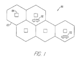
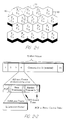
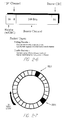
- FIG 2-1 is a diagram of a preferred cellular environment in which the invention may operate.
- a geographical region is divided into a plurality of cells 103.
- Associated with each cell 103 is an assigned frequency and an assigned spread spectrum code.
- Preferably, three different frequencies F1, F2 and F3 are assigned in such a manner that no two adjacent cells have the same assigned frequency F1, F2 or F3. The effect of such a frequency reuse pattern is to minimize interference between adjacent cells.
- different orthogonal spread spectrum codes C1 through C6 are assigned as shown in adjacent clusters 110. Although six spread spectrum codes C1 through C6 are shown in Fig. 2-1, it is contemplated that fewer or more spread spectrum codes may be suitable depending upon the particular information. Further information regarding a preferred cellular environment may be found in U.S. Application Serial No. 07/682,050 entitled “Three Cell Wireless Communication System” filed on April 8, 1991 in the name of Robert C. Dixon, and hereby incorporated by reference as if fully set forth herein.
- the preferred spread spectrum bandwidth may differ according to the frequency band of operation.
- the center frequencies F1, F2 and F3 are preferably located at 2.5 Mhz, 7.5 Mhz, and 12.5 Mhz, respectively, from the lowest band edge of the A, B or C frequency band.
- the spread spectrum chipping rate When operating in the PCS unlicensed band, which has a bandwidth of 20 Mhz divided into individual channel only 1.25 Mhz wide, the spread spectrum chipping rate may be reduced to approximately 1.25 Mcps.
- the TDMA burst rate, or number of TDMA time slots (or minor frames) in each polling loop, may also be reduced to maintain the required spread spectrum processing gain for rejecting intercell interference.
- a non-spread spectrum TDMA/TDD signal modulation format for operation in the unlicensed band may also be provided.
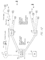
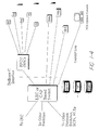
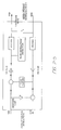
- Figure 1-2 is a diagram of a network architecture showing various system components.
- a preferred communication system is designed around an object-based software architecture which allows for flexibility in interconnection to various networks including public switched telephone networks, AIN, GSM and IS-41 network infrastructures. It is also contemplated that the communication system may interface with a cable television distribution network; however, such an interface may require the addition to the cable television network of a switch architecture, two-way amplifiers, redundancy, and, in order to use the coaxial portion of the cable TV network, a remote antenna subsystem to extend coverage from a base station 104.
- the overall system thus provides flexibility to interface with a variety of different networks depending upon the desired application.
- the system uses internal communications based on ISDN messages, called “notes”, for passing necessary information among components within the system. These "notes” are so named as not to confuse them with the ISDN specific protocol itself.
- Network messages (based on, e.g., Q.921, Q.931 protocols, or others) are converted by the system into “notes” for efficient operation within the hardware platform.
- Fig. 1-2 various components of a preferred system architecture including a plurality of base stations 104 for communicating with user stations 102.
- Each base station 104 may be coupled to a base station controller 105 by any of a variety of linking means 109 including, for example, local area data access (LADA) lines, T1 or fractional T1 lines, ISDN BRI's, cable TV lines, fiber optic cable, digital radio, microwave links, or private lines.
- LADA local area data access
- T1 or fractional T1 lines ISDN BRI's
- cable TV lines fiber optic cable
- digital radio microwave links
- Each base station controller 105 may be connected to a network 106 such as a public switched telephone network (PSTN) or a personal communications system switching center (PCSC) by a variety of network links 108, which include the same basic categories of transport means as the linking means 109.
- Base station controllers 105 may also connect to the network 106 via an X.25 link 114.
- the system of Fig. 1-2 also incorporates the use of "intelligent" base station (IBS) 107 compatible with LEC-based AIN architecture that may be connected directly to a network 106 without the interface of a base station controller 105.
- the intelligent base stations 107 may therefore bypass the base station controllers 105 for local handoffs and switching, and instead perform these functions via the network 106.
- signaling between network elements may be carried out using standard signaling protocols including, for example, SS7 and IS-41.
- the base stations 104 format and send digital information to the base station controller 105 (or directly to the network 106 in the case of an intelligent base station 107).
- the base station controllers 105 concentrate inputs from multiple base stations 104, assist handoffs between base stations 104, and convert and format channel information and signaling information for delivery to the network 106.
- the base station controllers 105 may also manage a local cache VLR database, and may support basic operations, administration and management functions such as billing, monitoring and testing.
- Each base station controller 105 under control of the network 106, may manage local registration and verification of its associated base stations 104 and may provide updates to the network 106 regarding the status of the base stations 104.
- the network 106 connects to the base station controllers 105 for call delivery and outgoing calls.
- the connection between the network 106 and a base station controller 105 may utilize the Bellcore "Generic C" interface which includes Q.921, Q.931 and modifications to Q.931.
- Intelligent base stations 107 may use ISDN messaging for registration, call delivery and handoff over a public telephone switch.
- the intelligent base station 107 may have all the general capabilities of a base station 104 but further incorporate a BRI card, additional intelligence and local vocoding.
- the connection between the network 106 and an intelligent base station 107 may utilize the Bellcore "Generic C" interface which includes Q.921, Q.931 and modifications to Q.931.
- base stations 104 may connect to the network 106 through a defined "A" interface.
- GSM Global System for Mobile communications
- the system may also interconnect to cable television distribution networks.
- the base stations 104 may be miniaturized to the point where they can be installed inside standard cable TV amplifier boxes. Interfacing may be carried out using analog remote antenna systems and digital transport mechanisms. For example, T1 and FT1 digital multiplexer outputs from the cable TV network may be used for interfacing, and basic rate (BRI) ISDN links to transport digital channels.
- BRI basic rate
- Cell site diagnostics may be performed remotely through either the control channel on the digital link resident in the base station 104 or a dial up modem for some implementations. Such diagnostics may be performed on each component board of the base station 104.
- the base stations 104 and base station controllers 105 may be remotely monitored and downloaded with updated software as required.
- user stations 102 can also be downloaded with software over air channels as required for maintenance purposes or for system upgrades.
- the user stations 102 comprise in one embodiment mobile handsets capable of multi-band and/or multi-mode operation.
- the user stations 102 may be multi-mode in that they may be capable of either spread spectrum communication or conventional narrowband communication.
- the user stations 102 may be multi-band in the sense that they may be set to operate on a plurality of different frequencies, such as frequencies in either the licensed or unlicensed frequency bands.
- a user station 102 may be set to operate on any frequency between 1850 and 1990 MHz in 625 kHz steps.
- each user station 102 may have a frequency synthesizers which can be programmed to receive and transmit on any one of 223 frequencies.
- the programmable frequency steps may be in 5 MHz increments, in which case the first channel may be centered at 1852.5 MHz, the next at 1857.5 MHz, and so on.
- the first channel may be centered at 1920.625 MHz, and the channel spacing may be 1.25 MHz across the remainder of the isochronous band.
- the user stations 102 need not operate in the 1910 to 1920 MHz band, which is reserved for asynchronous unlicensed devices.
- Vanderpool entitled “DUAL-MODE TRANSMITTER AND RECEIVER,” each of which is hereby incorporated by reference as if fully set forth herein.
- the multi-band, multi-mode capability enables the user stations 102 take advantage of variety of diverse system architectures as described herein, and to interface with various different networks with a minimum of hardware or software adjustments.
- Base stations 104 may also be provided with multi-band and multi-mode capabilities as described above.
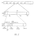
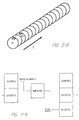
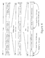
- Figure 2 shows frame and message formats in a polling loop.
- a base station 104 may poll user stations 102 in the cell 103.
- the base station 104 may repeatedly transmit a major frame 201, comprising a sequence of minor frames 202.
- each minor frame 202 may comprise a polling exchange for a single user station 102, while each major frame 201 may comprise a complete polling sweep of user stations 102 in the cell 103.
- the base station 104 may conduct its polling exchanges using a set of air channels 203.
- Each of the air channels 203 may comprise a separate transmission channel, such as a separate frequency band for FM or AM encoding, a separate spreading code for spread-spectrum encoding, a separate spatial location, or other division of communication slots between base stations 104 and user stations 102.
- the base station 104 may poll every one of its air channels 203 in a predetermined sequence in a single major frame 201.
- the base station 104 may poll every one of its air channels 203 in a single major frame 201, but it will be clear to those of ordinary skill in the art, after perusal of this application, that the base station 104 may restrict its poll to only a portion of its air channels 203 in each major frame 201, so long as all air channels 203 are eventually polled, and in an order so that each user station 102 may determine in which minor frame 202 it should respond.
- Each minor frame 202 may comprise a base transmission 204 by the base station 104, a first gap 205, a user transmission 206 by a user station 102 (if any user station 102 responds), and a second gap 207.
- a user station 102 desiring to establish a communication path may receive the base transmission 204 and determine if the air channel 203 is occupied or not. If not occupied, the user station 102 may respond with its user transmission 206.
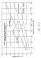
- cell radii in order to provide efficient service in low density rural areas, cell radii can be extended to large distances (e.g., beyond 8 miles) by providing the increased guard times as would be required for the longer round trip propagation delays encountered in the larger cells.
- Cells with large radii can be supported by reducing the number of minor frames 202 per major frame 201 to a lesser number (e.g., from 32 to 25). Since such large cell radii will ordinarily be deployed in low population density areas, reduced cell capacity caused by the smaller number of minor frames 202 per major frame 201 is not a severe drawback.
- a base transmission 204 may comprise a header field 207, which may be a fixed length of sixteen bits, a D field 208, which may be a fixed length of eight bits, and a B field 209, which may be a fixed length of 160 bits, or may be a variable length.
- the variable length may be determined in response to the polling loop time and the data rate which must be supported.
- the B field 209 may be 160 bits long.
- the user transmission 206 may comprise like fields as the base transmission 204.
- the header field 207 may comprise an origin bit 210, which may be a "1" bit for base transmissions 204 and may be a "0" bit for user transmissions 206. Other parts of the header field 207 may indicate information about the base transmission 204 or user transmission 206 itself, e.g., what type of message the base transmission 204 or user transmission 206 comprises.
- the header field 207 may also comprise a CSC or CRC code 211 (a cyclic redundancy check) having four bits.
- the D field 208 may comprise control information to be communicated between base stations 104 and user stations 102 once a communication link is established. This control information may generally be used for ISDN communication between base stations 104 and user stations 102, such as control information generally communicated using the ISDN "D channel". Because the D field 208 is separate from but simultaneous with the B field 209 which normally handles the bulk of information transfer due to its higher data rate, the D field 208 may be used for paging applications, notifications (e.g., voice mail), short message service (similar to GSM), or other user applications. Thus, the simultaneous nature of the D field 208 and the B field 209 allows messaging functions even when the user station 102 is "in use”.
- the D field 208 may also comprise a user nickname 212 for communication from the base station 104 and a designated user station 102.
- the user nickname 212 may comprise a temporary identifier for the user station 102 selected by the base station 104.
- the B field 209 may comprise data, voice (encoded digitally or otherwise), or other information. In a preferred embodiment, the B field 209 may also comprise specified information for establishing communication links between base stations 104 and user stations 102. The B field 209 may also comprise its own FCW or CRC code 211 having sixteen bits (with 160 bits of information, a total of 176 bits).
- each minor frame 202 may be about 307 microseconds long
- each air channel 203 in a TDD or TDMA system
- each major frame 201 may be about 20 milliseconds long.
- information may be transmitted at a rate of five bits each 6.4 microseconds, using a 32-ary code-shift keying technique.
- each 6.4 microseconds one of 32 different codes may be transmitted, with 32 different possibilities equalling five bits of information.
- one of 16 different codes may be transmitted, with an additional phase bit on the carrier (or, in a second alternative, more than one phase bit on the carrier), again with 32 different possibilities equalling five bits of information.
- a minor frame 203 may operate in an asymmetric mode in the sense that the greater portion of a minor frame 202 is devoted to either the base transmission 204 or the user transmission 206.
- High speed data transport in either direction i.e., from the base station 104 to the user station 102, or vice versa
- a particular sub-mode of the above described asymmetric mode may be referred to as broadcast mode in which essentially the entire minor frame is devoted to one-way communication.
- one or more broadcast sub-channels may be identified by a special broadcast identifier. Up to 255 broadcast channels may be so identified. For these point-to-multipoint applications, broadcast frames are not acknowledged.
- a user station 102 in a cellular environment preferably has means for controlling transmission power to avoid interference with adjacent cells.
- the nature of a cellular environment with mobile user stations 102 is such that there can arise conflict between user stations 102 at intersecting cell boundaries. This creates the need for some power control in the user stations 102.
- a user station 102 operating at the boundary of coverage of a base station 104 may need to transmit at full power to stay in contact.
- a user station 102 operating relatively close to its own base station 104 may not need to transmit full power to have good contact.
- user stations 102 may maintain adequate contact with base stations 104 without unduly interfering with neighboring cell transmissions, allowing RF channel reuse in nearby cells. Power control may also reduce interference with fixed microwave users and conserve battery power in user stations 102 such as handheld units.
- the present invention achieves power control in one embodiment by use of a power control pulse transmitted periodically from each user station 102.
- a control pulse time 213 and a third gap 214 may be reserved just prior to the start of the minor frame 202, in which the user station 102 transmits a control pulse 215.
- the control pulse 215 provides to the base station 104 a power measurement of the air channel 203 indicative of the path transmission loss and link quality.
- Each user station 102 generally transmits its control pulse 215 in the minor frame 202 allocated to it (e.g., seized by the user station 102).
- the control pulse 215 may be received by the base station 104 and used by the base station 104 to determine information about the communication link it has with the user station 102. For example, the base station 104 may determine, in response to the power, envelope, or phase of the control pulse 215, the direction or distance of the user station 104, and the degree of noise or multipath error to which the communication link with the user station 102 may be prone.
- the base station 104 determines the quality of the received signal including, for example, the received power from the power control pulse 215 and the signal-to-noise or interference ratio. The base station 104 then sends a message to inform the user station 102 to adjust its power if needed. Based on the quality of the received signal, the base station 104 may command the user station 102 to change (increase or decrease) its transmit power by some discrete amount (e.g, in minimum steps of 3 dB) relative to its current setting, until the quality of the control pulse 215 received by the base station 104 is above an acceptable threshold.
- some discrete amount e.g, in minimum steps of 3 dB
- the base station 104 can adjust its own power as well.
- the base station 104 may adjust its power separately for each minor frame 202.
- a preferred power control command pulse from the base station 104 to the user station 102 may be encoded according to Table 5-1 below: Power Control Command Adjustment 000 No change 001 -3 dB 010 -6 dB 011 -9 dB 100 +3 dB 101 +6 dB 110 +12 dB 111 +21 dB
- TDMA Time Division Multiple Access
- the length of the polling loop e.g, the major frame 201
- the latency of the polling loop signals may prevent the use of closed loop power control.
- the described embodiment allows for a power control sequence that may be effectively carried out in a relatively short span of time, thereby allowing closed loop power control.
- the elapsed time encompassing transmission of the control pulse 215, the base transmission 204, and the start of the user transmission 206 is kept relatively short (e.g., less than 500 ⁇ sec or roughly 2.5% of the duration of the major frame 201), allowing system response to be fast enough to counteract small scale multipath fading effects and propagation shadow effects.
- the base station 104 may also use the control pulse 215 to measure the time delay from a user station 102 and thereby estimate the distance of the user station 102 from the base station 104.
- a user station 102 can provide control pulses 215 to multiple base stations 104 for rough location estimation in emergency situations.
- the base station 104 may have a plurality of antennas for reception and transmission on the communication link with the user station 102, and may select one of that plurality of antennas for reception and/or transmission, in response to the determination the base station 104 may make in response to the control pulse 215.
- the base station 104 may make the determination of which antenna to use based on the quality of the signal received from the control pulse 215 transmitted by the user station 102. Because the base station can both receive and transmit on the antenna having the best received signal quality from the control pulse 215, the user stations 102 benefit from antenna selection diversity even though they might not have explicit antenna diversity capabilities at the user station 102.
- the control pulse 215 permits spatial diversity control to be updated during each minor frame 202.
- the base station 104 employs a high speed TDD technique such that the RF channel characteristics do not change within the time of the minor frame 202.
- Information relating to the control pulse 215 for a particular user station 102 may be transferred as information in control traffic from one base station 104 to another base station 104 in the case of a base station assisted handoff.
- control pulse 215 is primarily to reduce battery consumption in user stations 102, to minimize interference of transmissions among neighboring cells 103 which may be operating on the same or adjacent RF channels, and to minimize interference with nearby fixed microwave users.
- the control pulse 215 may also serve as a synchronization preamble for determining the beginning of M-ary data symbols within the minor frame 202.
- a power control command pulse similar in length to the control pulse 215, transmitted by the base station 104 during the base transmission 204 or otherwise may likewise be used as a synchronization preamble at the user station 102, in addition to providing a power control command to adjust the power output level at the user station 102.
- a single base station 104 may communicate with a large number of user stations 102 (e.g., as many as 64 user stations 102) at a given time, each of whose distance from the base station 104 may vary from near zero up to the radius of the cell 103, it may not be practical to control the transmitter power of the base station 104 in order to maintain a near-constant received power level at each user station 102 during each minor frame 202.
- Output power control of the transmitter at the base station 104 could require a large change (e.g., more than 40 dB) in transmit power during each minor frame 202 (e.g., every 625 ⁇ s) of the major frame 201.
- output power control at the base station 104 can be averaged over a longer time interval than each minor frame 202.
- time division duplex permits common antennas to be used for transmit and receive functions at both the base station 104 and the user stations 102, without the need for antenna diplexers. Common antennas can be used to transmit and receive because these functions are separated in time at each of the terminals. Further, because TDD utilizes the same RF frequency for the transmit and receive functions, the channel characteristics are essentially the same for both the base station 104 and a particular user station 102.
- the use of common antennas results in simplicity of the base station 104 and user station 102 terminal designs. Further, use of the same RF frequency and antenna for both transmit and receive functions at the base station 104 and the user station 102 provides reciprocal propagation paths between the base station 104 and user station 102 terminals. This reciprocal nature allows the base station 104 to use the channel sounding of the control pulse 215 transmitted by the user station 102 to determine the two-way path loss between the base station 104 and the user station 102, and also to determine which of the spatial diversity antennas at the base station 104 to use, both to receive from the user station 102 and to transmit to the user station 102.
- an omnidirectional antenna may be used to provide maximum coverage with the fewest base stations 104.
- an omnidirectional antenna may be employed having a vertical gain of approximately 9 dB. The 9 dB of gain permits a relatively large radius cell even with an omnidirectional horizontal pattern.
- directional antennas with 120 degree azimuth beamwidths and 9 dB vertical gain may be used at the base station 104 so that a cell 103 can be sectorized into three parts, with each sector accommodating a full load of user stations 102 (e.g., 32 full duplex user stations 102).
- TDD time division duplex demodulation
- a steered array antenna with up to 20 dB of horizontal directivity can be used.
- Such an antenna is sequentially steered to each user station 102 within a cell 103 at each minor frame 202.
- the same antenna may be used for both transmission and reception, as noted, providing reciprocal forward and reverse link propagation characteristics.
- the steered array antenna may utilize circular polarization so that high level delayed clutter signals reflected from buildings or other obstructions within the beam path do not interfere with the received signals from the user stations 102. As reflected signals are typically reversed in polarization, they will be rejected by the circularly polarized antenna. It should be noted that such high gain, directional antennas also reduce the delay spread in severe multipath environments by rejecting multipath components arriving from outside the main beam of the antenna.
- the user station 102 employs a halfwave dipole antenna which is linearly polarized and provides a gain of 2 dB with an omnidirectional pattern perpendicular to the antenna axis.
- a half wavelength is approximately 3 inches, which fits well within a handset envelope.
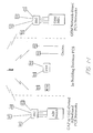
- Figure 3 shows message types and a protocol which uses those message types.
- messages may be one of three types: a general poll message 301, a specific poll message 302, and an information message 303.
- a message When a message is transmitted by a user station 102, it is called a "response", e.g., a general poll response 304, a specific poll response 305, and an information response 306.
- a user station 102 may "acquire" a base station 104 by a sequence of handshaking steps.
- the base station 104 may transmit its general poll message 301 on an air channel 203 as part of a minor frame 202.
- the user station 102 receives the general poll message 301 and, if and only if it was received without error, transmits its general poll response 304 on the same air channel 203.
- the general poll message 301 comprises a base ID 308, which may be 32 bits long, which may be recorded by the user station 102.
- the general poll response 304 comprises a user ID 309, which may be 32 bits long, which may be recorded by the base station 104.
- the base ID 308 may be used during handoff, as noted herein.
- the base station 104 may transmit a specific poll message 302, comprising the user ID 309 received by the base station 104 as part of the general poll response 304.
- the specific poll message 302 may be transmitted on the same air channel 203 as the general poll message 301, or may be transmitted on another air channel 203, so long as the user station 102 is able to find it.
- the user station 102 may monitor all air channels 203 for its specific user ID 309.
- the user station 102 receives the specific poll message 302 and, if and only if it was received without error and with the same user ID 309, transmits its specific poll response 305 on the same air channel 203.
- the specific poll response 305 comprises the same user ID 309 as the general poll response 304.
- the specific poll message 302 may be eliminated as redundant.
- the user station 102 may therefore follow the general poll response 304 with a specific poll response 305 on a selected air channel 203.
- This air channel 203 may be designated by the base station 104 in a part of the information field 209 of the general poll message 301, it may be designated by the user station 102 in a part of the information field 209 of the general poll response 304, or it may be selected by the user station 102 in response to an unoccupied air channel 203 (e.g., the user station 102 may seize an unoccupied air channel 203).
- the latter of these three alternatives is presently preferred by the inventors.
- the base station 104 may transmit an information message 303.
- the base station 104 and user station 102 have established a communication link 312 on a designated air channel 203, typically the air channel 203 originally polled by the base station 104, but possibly a different air channel 203.
- the base station 104 may couple a telephone line to that air channel 203, and the user station 102 may begin normal operation on a telephone network (e.g., the user station 102 may receive a dial tone, dial a number, make a telephone connection, and perform other telephone operations).
- the base station 104 and user station 102 may exchange information messages 303 and information responses 306, until the communication link 312 is voluntarily terminated, until faulty communication prompts the user station 102 to re-acquire the base station 104, or until handoff of the user station 102 to another base station 104.
- the base station 104 may advertently fail to respond.
- the lack of response from the base station 104 signals the involved user stations 102 to back off for a calculated time interval before attempting to acquire the same base station 104 using the general poll message 301 and general poll response 304 protocol.
- the back-off time may be based upon the user ID 309, and therefore each user station 102 will back off for a different length of time to prevent future collisions.
- the general poll message is sent by a base station 104 on one or more currently unoccupied air channels 203. Originally, at power-up of the base station 104, the base transmission 204 for all of the air channels 203 may therefore contain the general poll message 301.
- the base station 104 When an incoming telephone call is received at a base station 104, at an incoming-call step 313, the base station 104 transmits a specific poll message 302 with the user ID 309 of the indicated recipient user station 102 (skipping the general poll message 301 and the general poll response 304) on an available air channel 203.
- Each user station 102 listens for the specific poll message 302 repeatedly on each air channel 203 so as to receive the specific poll message 302 within a predetermined time after it is transmitted. Thus each user station 102 may periodically receive each air channel 203 in sequence so as to listen for the specific poll message 302.
- the user station 102 compares the user ID 309 in the message with its own user ID, and if they match, continues with the link-established step 311.
- the base station 104 may thus establish a communication link 312 with any user station 102 within communication range.
- the data transmission rate between a base station 104 and a user station 102 may be expanded or contracted over the duration of the communication link.
- the base station 104 increases the data transmission rate by transmitting multiple information messages 303 to the user station 102 during a major frame 201, essentially allocating multiple minor frames 202 to a single user station 102. These higher data rates, also known as "super rates", are implemented by means of a targeted information message 303.
- the base station 104 may transmit the user nickname 212 in the D field 208, along with information to be transmitted to the designated user station 102 in the B field 209.
- the user station 102 detects the user nickname 212 assigned to it, it receives the targeted information message 303.
- the user nickname 212 may be transmitted by the base station 104 to the user station 102 in the specific poll message 302. In an embodiment where the specific poll message 302 has been eliminated as redundant, the user nickname 212 may be transmitted by the base station 104 to the user station 102 bit-serially in a designated bit of the header field 207.
- the data transmission rate is related to the number of minor frames 202 allocated to a specific user station 102, the data transmission rate increases in steps of, for example, 8 Kbps. It is contemplated that up to the full bandwidth of the base station 104 -- that is, up to all 32 full duplex slots or 256 Kbps (full duplex) -- may be assigned to a single user station 102.
- the invention also provides in another aspect data rates lower than the basic rate (i.e., less than one minor frame 202 per major frame 201 or less than 8 Kbps).
- the lower data rate is accomplished by skipping major frames 201 on a periodic basis.
- data rates such as 4 Kbps, 2 Kbps, and so on can be provided.
- up to 24 consecutive major frames 201 may be skipped, providing a minimum data rate of 320 bps efficiently (i.e., without using rate adaptation). Intermediate rates or even lower rates may be obtained by using rate adaptation.
- each minor frame 202 can be configured with the majority of the minor frame 202 duration allocated to either the base transmission 204 or the user transmission 206, or can be configured with a symmetric distribution in which half of the minor frame 202 duration is allocated to both the base transmission 204 and the user transmission 206.
- voice traffic utilizes a symmetric distribution as either end of the link may send voice traffic. In a data exchange, however, more data is typically sent in one direction and less in the other.
- a higher data rate for the base transmission 204 would be advantageous and is supportable with the described configuration.
- a particular base station 104 or user station 102 may be assigned multiple minor frames 202 within a single major frame 201.
- These high data rate modes can support, for example, enhanced voice quality, video data or broadcast data applications.
- the user station 102 may receive all information messages 303 and transmit all information responses 306 on the same air channel 203 or on specified multiple air channels 203. This arrangement leaves the remainder of the major frame 201 free for other activities.
- one such activity is to interrogate other base stations 104 and maintain network information such as link quality and channel availability at nearby base stations 104 in order to facilitate handoffs from one base station 104 to another base station 104.
- base stations 104 transmit network information as part of the general poll message 301 and the specific poll message 302, in a channel utilization field 314 or otherwise.
- the network information may include, for example, the identity of nearby base stations, the identity or relative amount of free channels at a particular nearby base stations and/or at the current base station, link quality for nearby base stations and/or the current base station, and frequencies and spread spectrum code sets used by the nearby base stations.
- the user station 102 may listen on one or more different air channels 203, other than the one(s) currently being used by the user station 102, for the general poll message 301 and the specific poll message 302 from nearby base stations 104.
- the user station 102 continues to communicate on its designated air channel(s) 203 with its current base station 104 and responds as necessary to information messages 303 from that base station 104.
- the user station 102 does not transmit in response to other nearby base stations 104 and therefore does not occupy air channels 203 of those base stations 104.
- the system may perform either a "make before break” handoff for seamless, undetectable handoffs, or a "break before make” handoff in emergency situations where all communications with a base station 104 are lost prior to a new connection being established.
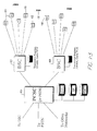
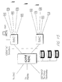
- a "make before break” handoff if the communication link 312 between the base station 104 and the user station 102 is too faulty, then the user station 102 may acquire one of the nearby base stations 104 in like manner as it acquired its current base station 104. Such a handoff procedure may be further explained with reference to Fig. 1-3.
- a user station 102 presently in communication with a current or original base station 405 has determined it to be desirable to transfer communication to a different base station 104, such as a first terminal base station 410 coupled to a common base station controller 407, or a second terminal base station 406 coupled to a different base station controller 408.
- a handoff to the first terminal base station 410 will be termed an "intra-cluster" handoff, while a handoff to the second terminal base station 406 will be termed an "inter-cluster" handoff.
- the user station 102 determines that a handoff is appropriate, the user station 102 acquires an air channel on the new or terminal base station 410 and notifies the base station controller 407 coupled to the current base station 405 to switch the incoming phone line from the current base station 405 to the new base station 410.
- a handoff procedure may be initiated when the received signal level at a user station 102 falls below an acceptable level. While the user station 102 receives bearer traffic from its originating base station 405, the user station 102 measures the received signal quality (e.g., RSSI) of its communication link 312. The received signal quality value, together with measurements of the current frame error rate and type of errors, determines the overall link quality. If the overall link quality drops below a first threshold (the measurement threshold), the user station 102 begins searching for available air channels 203 (i.e., time slots), first from the originating base station 104, and then (using appropriate frequencies and spread spectrum codes) from neighboring base stations 104 of adjacent or nearby cells 103. The user station 102, as mentioned, preferably has obtained information regarding the identities of neighboring base stations 104 (including spread spectrum code set and frequency information) from the originating base station 405 by downloading the information to the user station 102 during traffic mode or otherwise.
- the received signal quality e.g., RSSI
- the user station 102 scans potential new air channels 203 using the appropriate frequency and/or spread spectrum code set, the user station 102 measures and records the received signal quality.
- the user station 102 reads a field carried in all base transmissions 204 which describes the current time slot utilization of the base station 104.
- the user station 102 uses these two pieces of information to form a figure of merit for the new base station signals, including the originating base station 405, and then sorts the base stations 104 by figure of merit. This procedure allows the user station 102 to evaluate the quality of available air channels 203 for both the originating base station 405 and other nearby base stations 104.
- a time slot interchange (TSI) handoff is considered, which maintains the link to the originating base station 405 on a different air channel 203 than was previously being used by the user station 102.
- TTI time slot interchange
- the user station 102 requests a handoff from the base station 104 with the highest figure of merit (which could be a TSI handoff with the originating base station 405).
- the handoff is requested by seizing an air channel 203, sending a handoff message request, and waiting for an acknowledgment from the new base station 410.
- the handoff signaling message contains a description of the circuit connecting the originating base station 405 to the network, which description was passed to the user station 102 at call establishment time. If the new base station 104 accepts the handoff request (by acknowledging), then the new base station 104 becomes the terminal base station 410. Note that the user station 102 maintains its original air channel 203 connection with the originating base station 405 during this handoff procedure, at least until a new air channel 203 is acquired.
- a handoff step 316 the user station 102 transmits to the new base station 410 the base ID 308 of the old base station 405.
- the old base station 405 and new base station 410 may then transfer the handling of any telephone call in progress.
- the terminal base station 410 sends a message in the form of a "note" (as previously described) to its base station controller 407, requesting that the original circuit be switched from the originating base station 405 to the terminal base station 410.
- the base station controller 407 is common to both the originating base station 405 and terminal base station 410, the handoff is termed an intra-cluster event, and the base station controller 407 bridges the circuit from the originating base station 405 to the terminal base station 410.
- the base station controller 407 then sends a circuit-switch-complete note to the originating base station 405 and also to the terminating base station 410, commanding the latter to continue the handoff process.
- the base station controller 408 is not common to both the originating base stations 104 and the terminal base station 406.
- the terminal base station 406 sends a message in the form of a note to its base station controller 408, requesting that the original circuit be switched from the originating base station 405 to the terminal base station 406.
- the base station controller 408 translates the handoff note into the signaling language of the network host 409 (e.g, a PCSC) and requests an inter-cluster handoff at the network level.
- the host network 409 cannot accept a handoff request from a terminating base station controller 408, in which case an intermediate step is taken.
- the handoff request may be sent via an X.25 link to the base station controller 407 connected to the originating base station 405.
- the originating base station controller 407 then translates the handoff request and relays it to the network host 409.
- the network host 409 acknowledges the circuit switch to the originating base station controller 407, which then sends a circuit-switch-complete note to the terminal base station 406.
- the terminal base station 406 When the terminal base station 406 receives the circuit-switch-complete note, the terminal base station 406 begins paging the user station 102 with a specific poll, and the originating base station 405 signals the user station 102 to transfer to the terminal base station 406. When the user station 102 receives the signal to transfer to the terminal base station 406, or if the link is lost during the handoff process, the user station 102 switches to the terminal base station 406 and searches for a specific poll message 302. When the user station 102 receives the specific poll message 302, the user station 102 completes the connection to the terminal base station 406, and the handoff procedure is finished.
- the user station 102 will search for the highest quality base station 104 on its list of potential handoffs, and attempt a handoff without communication with its previous base station 405. This capability allows the user station 102 to recover from situations in which the original link was broken before the normal handoff procedure could be completed.
- An intra-cluster handoff including re-establishment of bearer channel traffic, may ordinarily take from less than 10 milliseconds to as much as 40 milliseconds. Since under normal circumstances the handoff time is less than one polling loop interval, bearer packets will continue to the user station 102 with no interruption. Inter-cluster handoff times are partially dependent upon the delays inherent in the host network 409 and are not always easily predictable.
- a unique aspect of the above described "mobile directed” or “mobile centric” handoff technique is that the user station 102 makes the decision to handoff between cells and directs the base station controller or network to make a line switch once an alternative base station 104 is acquired.
- This approach is quite different from a "network directed” or “network centric” approach such as used in systems such as AMPS, IS-54 cellular, and GSM.
- the mobile centric approach also differs significantly from so-called “Mobile Assisted Handoff” (MAHO) in which the network collects information and directs all or most of the handoff functions, thereby utilizing the user station 102 primarily as an additional listening post with the network still directing the handoff.
- MAHO Mobile Assisted Handoff
- the MAHO technique therefore ordinarily requires significant signaling and messaging between base stations, base station controllers, and switches, causing handoffs to take much longer than with the mobile centric techniques described herein.
- a major benefit of the mobile centric approach is that it may allow for mobile speed handoffs (e.g., 65 MPH) even in very small or very large cells, such as cells ranging from as small as under 1000 feet to as large as 20 miles in diameter.
- the system is also capable of performing a "break before make” type of handoff as well.
- a "break before make” handoff is typified in a situation where sudden shadowing occurs, such as when a connection with the current base station 405 is lost due to a severe signal blockage (e.g. worse than 40 dB) near the limit of the cell range such as can occur when turning a corner quickly in a dense urban high rise area.
- the user station 102 checks its previously created "priority list" of available base stations in the vicinity and attempts to establish contact with a new base station 104, perhaps on a new frequency and/or a new time slot.
- the user station 102 may include as part of its control logic a "persistence" parameter which will preclude call tear down from occurring before a duplex connection is fully reestablished.
- the true "hard handoff" problem i.e., a lost air channel
- the handoff may ordinarily be accomplished in as little as 16 to 250 milliseconds.
- complete loss of a link in traditional cellular architectures becomes a "dropped call.”
- One problem that may occur during handoff is a situation in which there are repeated attempts to switch between two or more base stations 104 during times, for example, when the measured quality of the received signals from two competing base stations 104 is very close, or when environmental effects cause rapidly changing deviations in the relative measured signal quality of the signals from competing base stations 104.
- the repeated switching between competing base stations 104 may be referred to as "thrashing" and may have the undesirable effect of consuming excess capacity from the network.
- hysteresis measurements from multiple base stations 104 may be maintained by the user station 102 so that a handoff does not occur until the quality of the signal from a new base station 104 exceeds the quality of the signal of the original base station 405 by a predetermined margin. In such a manner, important air channel resources in the network may be preserved.
- a time slot interchange may be performed wherein one or both of the conflicting user stations 102 are assigned different minor frames 202 within their respective major frames 201 to eliminate further collisions.
- TTI time slot interchange
- Such a procedure may be viewed as the time domain equivalent of dynamic channel allocation as the system either assigns an unoccupied air channel 203 to the user station 102 or switches the user station's 102 minor frame 202 with that of another user station 102 in the same cell 103 which is geographically removed from the interference.
- the protocol of the invention protects communications against errors in several ways: protocol handshaking, user ID verification and reverification, and synchronization by reacquiring the base station. Handshaking, verification and synchronization protect both the base station 104 and the user station 102 from receiving telephone calls in progress on any other air channels 203.
- Handshaking provided by the general poll step 307 and the specific poll step 310 requires that the proper message having the proper header be transmitted and received, and in the proper sequence.
- the header field 207 (sixteen bits) is protected by a CRC code 211 (four bits); an error in the header field 207 or in the CRC code 211 indicates an error and will cause the protocol to restart handshaking with the general poll step 307.
- the user ID is verified twice, once by the base station 104 and once by the user station 102.
- the user ID 309 is protected by a CRC code 211 (sixteen bits), in like manner as the CRC code 211 for the header field 207.
- An error in the user ID 309 or in the CRC code 211 will cause the protocol to restart handshaking with the general poll step 307.
- the base station 104 and the user station 102 are protected against drift and/or desynchronization, even when transmission or reception are interrupted.
- the base station 104 and user station 102 each independently stop sending data in information messages 303 and information responses 306, and return to the specific poll step 310 for resynchronization.
- the base station 104 and the user station 102 may determine resynchronization by means of a designated bit in the header field 207.
- the base station 104 transmits the specific poll message 302 and the user station 102 searches the major frame 201 for a specific poll message 302 having a user ID 309 which matches its own user ID 309. After this handshaking succeeds, the base station 104 and user station 102 return to the link-established step 311 and continue transmitting and receiving information messages 303 and information responses 306.
- This technique for recovery from desynchronization also called “reacquiring the base station,” has the advantage that both the base station 104 and the user station 102 independently reverify the user ID 309 before communication is resumed. This assures that the base station 104 and the user station 102 stay in synchrony and communicate only on the agreed air channel 203. Should the base station 104 and the user station 102 be unable to reestablish the communication link 312, the telephone call will be terminated by the base station 104.
- the base station 104 also repeatedly and periodically transmits the user ID 309 in the D field 208 of the information message 303.
- the user station 102 checks the user ID 309 to assure that the base station 104 and the user station 102 are each communicating on the proper air channel 203. If this user ID 309 does not match, it returns to the specific poll step 310 to reacquire the base station 104, as noted above.
- the protocol described above provides flexibility with a small number of unique messages.
- the protocol is immune to changes in polling loop length and in the number of air channels allowed.
- the number of simultaneous users is therefore responsive to voice compression and data rate constraints and not by the protocol.
- the protocol also provides for an unlimited number of user stations in a given area, with the provision that the number of simultaneous calls cannot exceed the number of air channels.
- An unlimited number of base stations are also supported, making base station geography a function of available frequencies and range, not of protocol.
- the ability to interrogate and acquire alternate base stations in the presence of faulty communication provides for the expansion of a microcell network which may use base station handoff to route calls to base stations within range.
- the TDMA frame times for all base stations 104 within a geographical region are preferably synchronized to within a specified tolerance. For example, in one embodiment, all base stations 104 begin transmissions for the same frame within 6 microseconds.
- the primary data timing standard in a digital network backhaul system such as T1, ISDN BRI, or PRI, is the public switched telephone network (PSTN) timing standard.
- PSTN public switched telephone network
- a GPS receiver is used at each base station controller 105 (and optionally at each base station 104) to generate the primary reference timing marker for the TDMA frame timing. This marker is captured at the base station controller 105 every second and transmitted to the attached base stations 104.
- a base station controller may temporarily turn off any major frame 201 or minor frame 202 of a given cell 103 which may be interfering with a neighboring cell 103.
- Each base station 104 provides the basic TDMA loop timing structure for its cell or sector.
- a synchronization preamble in the form a control pulse 215 or power control command is transmitted at the beginning of each minor frame 202 by the user station 102 and the base station 104, respectively.
- a digital correlator i.e., a matched filter
- an internal synchronization pulse which may be very brief (e.g., two chips in duration, or 400 nanoseconds) .
- the internal synchronization pulse may then be used to synchronize the start of M-ary symbol detection process.
- Omnipoint has developed an innovative spread spectrum RF access technology, communications protocol, and architecture for controlling Base Station resources and high speed handoff.
- Omnipoint's PCS System can be integrated into networks using AIN, GSM, IS-41 and ATM based architectures.
- Omnipoint's PCS System provides full functionality PCS - i.e. full coverage, full mobility, and high speed data up to 256 Kbps full duplex or 512 Kbps half duplex. Moreover, a single handset and Common Air Interface can be used in all three wireless markets: public, business and residential in either licensed or unlicensed frequency bands. Perhaps most importantly, Omnipoint's approach offers significant, sustainable infrastructure cost reductions and thus provides the PCS operator with long term economic advantages over alternative approaches .
- the Omnipoint system uses a proprietary combination of CDMA, TDMA, and FDMA for separation of users and cells.
- users are separated within a cell by a proprietary spread spectrum TDMA technology and cells are separated by FDMA as well as CDMA.
- the spreading codes are also used to achieve significantly higher data rates and thus more TDMA users per RF channel than generally thought possible with traditional TDMA systems without requiring the use of expensive and power consumptive equalizers.
- TSI Time Slot Interchange
- directional antennas and a unique mobile-centric approach to managing RF resources and handoff provide for extremely low cost and efficient provisioning of PCS.
- Omnipoint has implemented experimental prototypes of this technology into pocket phones and palm-sized data devices, as well as in miniaturized Base Stations.
- Omnipoint systems can be configured to provide outdoor cell radii of 0.3 to 2.2 miles in urban areas, 1 to 5 miles in suburban areas, and over 8 miles in more open areas (with proper antennae configurations and some reduction in the number of time slots).
- Omnipoint Base Stations have been tested in low density urban areas with up to 3 mile diameter cells with handsets operating at mobile speeds. Hand-off has been performed at 65 miles per hour in both large cells and small cells (for example, 1000 feet).
- Omnipoint's private systems can offer the features, data rates, and voice quality required to serve both business and residential users and thus differentiate PCS from cellular and other services which can only offer compressed voice and very low speed data.
- Omnipoint has developed its system specifically to serve both outside and indoor environments and has conducted successful experiments testing its indoor PCS systems in more than 100 buildings of virtually every size and type of construction imaginable. Further, to understand the needs of indoor users, Omnipoint has interviewed 180 of the Fortune 1000 telecommunications managers who purchase equipment and found that 1) none of them were willing to pay for air time charges while wireless on their own premises and 2) they all insisted on owning their own Base Station equipment and having it functionally integrated with their PBXs. This virtually requires the use of unlicensed frequencies in many locations if large market penetrations are to be achieved. Omnipoint's system is unique in using the same CAI to meet this private premises need in either unlicensed or licensed frequencies while allowing customers to use the same handsets in the outdoor, public, mobile environment.
- Omnipoint provides the ability for a subscriber to use 32-24 Kbps ADPCM if desired for wireline quality voice or 8 Kbps (and later 4 Kbps) for outdoor mobile environments.
- Omnipoint's system can provide 64 Kbps as well as multiples of 64 Kbps (up to 256 Kbps full duplex and 512 Kbps simplex) for data, video, multimedia, and broadcast applications. Additionally, the user can vary the data rate, requesting only the minimal rate necessary for the application. Omnipoint's system supports extremely fast circuit seizing and release (50ms, and typically less than 10ms) allowing for efficient provision of bursty packet data as well as slow speed data.
- Control traffic provides for link specific data messaging or call control information.
- Control traffic can be provided through a number of logical methods as detailed below, including a customer "D" channel associated with each time slot.
- Omnipoint implements network interfaces based on Q.931 ISDN and SS7 to the necessary network components.
- the Omnipoint system is designed around an object-based software architecture which allows for flexibility in interconnection to a number of network infrastructures.
- the system uses messages based on ISDN messages which are called "Notes” (so as not to confuse them with the ISDN specific protocol itself) for passing necessary information among components within the system.
- Messages from the network are converted by the system into Omnipoint "Notes” for efficient operation within the Omnipoint subsystems. This approach provides the PCS operator with flexibility to deploy whatever network infrastructure meets the appropriate business goals and service descriptions desired.
- This section contains the list of minimum service capabilities required of a PCS system. For each item, the Omnipoint system indicates which of these features will be supported.
- Omnipoint's access system is being integrated into various types of Network Architectures such as AIN, Americanized GSM, IS-41, and ATM-based systems.
- the availability of a specific feature/service is thus determined by when the PCSC network architecture supports it.
- Feature/Service (133R1) GSM-Type Network AIN-Type Network 2.1.1 Advice of charging E* - F E* - F 2.1.2
- Alphanumeric display messages I I 2.1.3 Automatic charge reversing E* - .2 E* - F 2.1.4.
- Authorization code I E* - .2 2.1.5.
- Multi-level Precedence and Preemption E - F E* - F 2.1.29.
- Priority Access and Code/Channel Assignment I E* - .2 2.1.30.
- Remote feature control E* - .2 E* - .2 2.1.31.
- Reverse charging E* - .2 E* - .2 . 2.1.32.
- Selective call acceptance E* - .2 E* - .2 2.1.33.
- Selective call rejection E* - .2 E* - .2 2.1.34.
- Selective call forwarding E* - .2 E* - .2 2.1.35.
- Smart card I E* - .2 2.1.36.
- Three-way calling I I 2.1.37.
- User profile editing E - .2 E* - .2 2.1.38.
- Emergency Access I I I I 2.1.37.
- User profile editing E - .2 E*
- the Omnipoint system provides land line quality voice services to the end user for wireless access to the network.
- the system is designed to provide transparent operation for the user to network functionality including DTMF tones for interactive services, music on hold, and the provision of active call features to remain intact even after a handoff between cell sites.
- Higher levels of voice quality can be provided by the system in increments of 8 Kbps (and in the future, at even lower vocoder rates) without any change to the Base Stations or the CAI.
- this class of service is made known to the system at call set-up time and CCITT G.726 standard ADPCM is executed. CCITT G.726 is fully supported.
- CCITT G.726 64 Kbps PCM is also supported as well as a proprietary 8 Kbps CELP algorithm.
- Lower channel rates, such as 4 Kbps, are also supported to allow for future upgrades without any changes to the CAI or the Base Station hardware.
- VAD Voice Activity Detection
- "half duplex" can be supported, allowing up to twice the number of voice users in a particular RF channel.
- Voice services provided by Omnipoint will be available to end users in both mobile and non-mobile environments. See Section 4.3.1
- Circuit mode digital data is supported across the air interface.
- Inter working Function used is dependent upon the network or circuit switch service chosen in a particular network.
- the system provides full duplex synchronous data transfer over-the-air in dynamically variable data rates, see above "Inter working with Circuit Switched Digital Services".
- the terminal application may use a data channel to communicate with a Packet Assembler/Disassembler (PAD) and/or IWF using these facilities.
- PID Packet Assembler/Disassembler
- IWF Inter-working with Circuit Switched Digital Services
- X.25 packet data is supported. During times of low data rates the terminal will reduce its over-the-air bandwidth requirement accordingly.
- the system provides a very fast circuit seizing protocol. Since contention for a channel can occur at this point it is resolved with an IEEE 802.3-like backoff procedure. Since the overhead for channel seizing and release is very low (sub 50 ms and typically, sub 10 ms), a transaction based application will acquire a channel, build a circuit to the appropriate IWF module, send its data, and release the channel very quickly. Very low data rate applications will have a very low channel access duty cycle.
- Omnipoint System Since the Omnipoint System is designed as an "access and transport mechanism," it will be able to support many different specialized data applications as noted above.
- Error correction in bearer data is optional in the system.
- the end user has the option of activating Automatic Re-transmission Query (ARQ) error correction or leaving error correction disabled, for example, for use with digitized compressed video.
- ARQ Automatic Re-transmission Query
- the ARQ mechanism uses a data window of two frames.
- a frame is determined to be corrupted, via the standard ISDN 16 bit Frame Check Word (FCW)
- FCW Frame Check Word
- the receiving unit signals the transmitter for a re-transmission.
- the number of re-transmission attempts is a service provider or subscriber parameter.
- the maximum uncorrected frame error rate of the system is 10 -2 at threshold receiver sensitivity (See Section 4.6.1). After applying ARQ correction the frame error rate at threshold is: 10 -2 /(2 16 -1) which is 1.53 X 10 -7 undetected frame errors.
- Data rate and integrity are maintained before and after handover. Since data may be lost during the handover, the system uses higher level protocols, i.e. not the CAI, to correct the loss of frames.
- a typical handover delay, including switch time, for an intra Base Station Controller handover is less than 10 ms.
- the maximum handover time assuming that communication with the Terminal Base is error free, is approximately 40 ms.
- the system supports an out-of-band logical D channel in conjunction with speech or data.
- This channel supports acknowledged ISDN D channel services at a rate of 400 bit/s with no interference to the bearer channel.
- inband signaling either half or full duplex, can be used for larger messages. Inband signaling will temporarily displace the user level bearer channel traffic.
- Very high speed paging may be sent via the unacknowledged data broadcast facility. Using this facility, data at up to 512 Kbps can be sent over the air interface. This mode does not address specific units. It is assumed that an MS resident application will interpret the format of data in the broadcast format.
- the Omnipoint system will support authentication (the process of verifying the identity of a user, terminal and service provider) and validation (the process of verifying that a user and/or terminal is authorized to access services).
- the authentication and validation process will permit the system operator to separate fraudulent wireless devices, unauthorized users, and authorized users before service is granted. This prevention can extend to both speech as well as data services.
- the Omnipoint system will support privacy of signaling and user information (e.g., speech and data) and will maintain the privacy of the user identity and location.
- the Omnipoint system can allow protection against unauthorized use by requiring the user to enter a PIN.
- the portable will default to requesting the user for the PIN upon powering up the device. This default can be disabled through an appropriate control function.
- Omnipoint's system can support the use of SIMs.
- the final methodology for supporting privacy and authentication in the Omnipoint system will be determined by industry efforts, specifically from the Joint Experts Meeting on Privacy and Authentication or as otherwise determined by the PCS operators.
- the air interface facilitates invocation of user functions in a consistent fashion.
- the MS provides for feature invocation by keypad digit entry, function key and dynamic menu.
- Omnipoint supports future user feature activation standardization at the keyboard/display level.
- the Air Interface Signaling method used by the system for feature invocation is based upon ISDN Q.931/ANSI T1.607 signaling.
- an abbreviated format is used in the over-the-air messaging. These messages are converted to the appropriate ISDN messages at a higher level in the system architecture.
- Data and voice may be mixed to a total full duplex rate of 256 Kbps or 512 Kbps simplex in steps of 8 Kbps.
- This allows, for example, toll quality voice, 32 Kbps ADPCM, and simultaneously up to 224 Kbps of full duplex data.
- low rate data can be sent simultaneously over the D channel without requiring additional time slots.
- Selection of the vocoder algorithm is made by the call originating party at call setup time. This is done either by automatically accessing the user's HLR data base for the default selection and selecting the vocoders at each end of the link or alternatively, the subscriber can select vocoder options at call origination.
- the Omnipoint Terminal can transmit dialed digits using logic recognizing the North American Dialing Plan, eliminating the requirement for a traditional "Send" button to dial digits in basic operations. Alternatively, the Send button can be used.
- DTMF signaling out-of-band across the air interface is supported.
- the DTMF tones will be sent by network conversion of the messages into tones by a higher order architectural element. DTMF tones will not be carried by the audio bearer channel. DTMF tone will be transported back to the MS.
- the Omnipoint terminal has a "flash" button which transmits signaling across the air interface out-of-band to indicate to the network that a switchhook flash has occurred.
- the actual hook flash is generated by a higher order architectural element.
- the Omnipoint terminal will have an indicator displaying either a "home” registration or a visitor "roam” registration. This indicator will be activated by service provider identification that is associated with the general poll frame from the Base Station.
- Full duplex video up to 256 Kbps in steps of 8 Kbps, half duplex video of up to 512 Kbps in steps of 8 Kbps and 8 Kbps audio with simultaneous video up to 248 Kbps are supported.
- JPEG and MPEG standards are supported.
- Digital rates of 144 Kbps in the form of an ISDN BRI channel that is 2 * 64 Kbps + 1 * 16 Kbps, are supported.
- the air interface can carry the Q.931/T1.607-like messaging necessary to invoke AIN functions.
- Each service provider is identified by the Base Stations during the acquisition phase of a call. Actual access to the provider is controlled by the subscribers profile and by SIM information at the terminal.
- Outbound delay ( ⁇ sec) : speech plus radio for "outbound" path (wireline to wireless) - delay between H2 and A2. (Signal applied at H2.) 20.02 msec.
- Echo return loss (ERL) (dB): ratio of H2 to H1, with signal injected at H2. 30 dB min. Synchronization requirements: Is Base Station to Base Y Station synchronization required? (Y/N) Is Base Station-to-network Y synchronization required? (Y/N) State short-term stability .001 ppm/sec of internal base (or base controller) system reference clock (ppm).
- the Omnipoint system utilizes DSP based digital echo cancellation techniques in the transcoder on the base station controller. This algorithm has an adaptive long term length of up to 5.5 msec. Maximum Tolerable Delay Spread (in ⁇ sec) to maintain an uncorrected FER _ 10 -2 . up to 3 ⁇ sec Do you employ equalization? (Y/N) N Maximum Tolerable Doppler Frequency (Hz) to maintain an uncorrected BER _ 10 -3 +/- 10 KHz Maximum User Bit Rate: 512 Kbps Operating Temperature Range: -40° to +70° C
- the Omnipoint system is composed of the following four network hierarchical elements; Mobile Station (MS), Base Station (BS), Base Station Controller (BSC), and a Personal Communications Switching Center (PCSC).
- MS Mobile Station
- BS Base Station
- BSC Base Station Controller
- PCSC Personal Communications Switching Center
- MS Mobile Station
- the Mobile Station is the subscriber terminal. It communicates with one Base Station (more during handover) and is responsible for the following:
- the Omnipoint MS controls the handover actions of the system. It is responsible for monitoring the quality of the ongoing bearer connection with its current Base Station as well as the quality of signals received from other nearby Base Stations/Cells. If the quality of the bearer channel drops below an acceptable level the MS will initiate a handover to a better BS. The MS is also responsible for maintaining registration with its current BS as well as directing the BSC to make a switch of BS's as part of the handover.
- the MS is responsible for initiating outgoing call requests and periodically monitoring for incoming call pages. Page monitoring is scheduled on duty cycle basis to reduce power consumption.
- the MS maintains the over-the-air channel from the mobile perspective. It performs all necessary timing, slot aggregation and error recovery.
- the MS maintains the subscriber secret key and performs the required calculations necessary to authenticate the device.
- the MS executes the appropriate downloadable user applications.
- the applications implement the short messaging service, broadcast messaging and data services. Additional user specific applications using the system data services may also be downloaded and executed.
- the MS implements the feature activating subscriber interface as well as the interface to specific downloaded applications in the MS.
- BS Base Station
- the Base Station is an intelligent device which controls the over the air signal and serves as Cell controller. It communicates with multiple MSs and a Base Station Controller. It provides the following functionality:
- the BS controls the over-the-air slots of the TDMA spread spectrum transceiver.
- the BS allocates these slots based upon MS initial service requests, handover bandwidth demands, special service needs and OA&M test and operational restrictions.
- the BS is the component which is charged with allocation of specific slots, super-slots, and sub-slots to maintain the requested bandwidth.
- the BS responds to MS handover requests if resources are available.
- the BS assigns network and radio resources to the MS and sends a request to the Base Station Controller to execute a handover switch.
- the BS also maintains registrations with MSs within its Cell. This registration information is maintained in a stub or cache Visitor Location Register (VLR).
- VLR Visitor Location Register
- Time Slot Interchange This function allows a Mobile or a Base Station to change the operational time slot if interference is detected, taking advantage of statistical placement of Mobile Stations in both the original and re-used cells.
- the system supports very quick TSI, within a single polling loop (i.e., less than 20 msec), as required and available.
- the BS interprets the over-the-air signaling traffic and translates this traffic from its concise form to an appropriate network independent format called Notes. These Notes have been designed to reduce network latency and bandwidth while communicating succinct information to the higher elements in the network.
- the BS is responsible for the allocation of network channels to their corresponding air slots.
- the BS controls these resources for both incoming and outgoing calls. Audio connections over network channels are maintained in their compressed form.
- multiple network time slots may be assigned to a specific MS.
- the BS is also responsible for monitoring the interference on the radio and adjusting its slot utilization to minimize this interference.
- the BS measures signal quality from its MSs and selects antennas for space diversity and polarization when appropriate, as well as controls the MS power.
- the Base Station responds to Notes from the Base Station Controller to authenticate a given MS.
- the BS sends the appropriate over-the-air signals to the MS and compares the authentication response against the proper value.
- the Base station maintains accounting information for each connection in an accounting log. This information along with maintenance statistics are transferred to the Base Station Controller and higher level entities via Notes. Notes are also used to block, unblock, and loopback-test network channels for maintenance purposes.
- the PCSC also provides OA&M.
- BSC Base Station Controller
- the Base Station Controller is an intelligent switch which controls and performs switching functions for a group of Base Stations called a cluster. It communicates with multiple Base Stations, and a PCSC.
- the Base Station Controller functionality is:
- the BSC interprets handover requests from its Base Stations. If the handover request represents an intra cluster handover, i.e. between two Base Stations on the same BSC, the BSC switches all of the circuits associated with the MS from the originating BS to the terminating BS. If the handover request indicates that the originating BS is located on some other BSC then the handover Note is translated into a form appropriate for the host PCSC and this form is forwarded to the host PCSC.
- the BSC is responsible for cluster location of the MSs. Registration information forwarded from a BS is recorded in a local stub Visitor Location Register (VLR) located in the VLR.
- VLR Visitor Location Register
- BSC This is used to locate the MS during alerting operations. Line resource requirements forwarded from the BS are also held in this stub VLR. Furthermore, the BSC translates the commands and data contained in Notes passed to it by the BS into signaling suitable for the host PCSC system. In this sense the BSC acts as a translator between the Omnipoint system and the host system.
- the BSC is responsible for allocation and termination of the trunking circuits between the BSC and the host PCSC.
- the BSC is also responsible for the transcoding of compressed audio to the trunking format.
- the BSC further serves as an Inter-Working-Function between the Omnipoint data channelization format and other network formats.
- the BSC stores accounting information delivered to it by the BSs. This information is translated into a form suitable for the host system and forwarded to the PCSC. In addition the BSC is responsible for blocking, unblocking and loop testing circuits upon request from the PCSC.
- PCSC Personal Communications Switching Center
- the PCSC is the primary switch and the interconnect to the PSTN.
- the Omnipoint system has been designed to connect to a variety of existing and proposed switch systems, including the AIN network, the Americanized version of GSM, IS-41, and ATM-based networks. The operation of these systems is outside the scope of this response.
- the PCSC provides inter cluster and inter PCSC handover capability.
- the PCSC provides Home Location Register (HLR) and Visitor Location Register (VLR) services.
- HLR Home Location Register
- VLR Visitor Location Register
- Authentication requests and data are initiated by or stored in the PCSC.
- Omnipoint Base Stations are designed to be small enough to install with minimal real estate requirements. For example, Omnipoint's Micro Base Station at 9"x 4"x"12" allows for Base Stations to be hung from a telephone or CATV strand, mounted to a telephone or light pole, or installed in a weather-proof NEMA style enclosure. Omnipoint Base Stations have been installed inside of "live" cable TV amplifier enclosures. Indoor models may be mounted above ceiling tiles in a typical office building with the antennas mounted on either the exterior of the building or inside.
- Standard Base Station Controllers (BSC) handling up to 1600 Voice Ports are likewise comparatively small, and generally require no more real estate than a phone closet where standard 19" equipment may be placed.
- Omnipoint system provides for comprehensive operational support for PCS which will include central monitoring of the system, software upgrades, simple repair procedures, easy installation and test, and the ability to interconnect with a variety of different platforms such as AIN, the Americanized version of GSM, IS-41 and ATM based networks. In general, the following are provided by Omnipoint:
- the Omnipoint system provides for remote monitoring of the Base Stations and Base Station controllers via a digital facility. Information provided includes loading, diagnostic processes, and other support mechanisms. With this capability, the system can be monitored from a central site (perhaps by a third party) in conjunction with other network component monitoring (e.g., network control center for the PSTN).
- network component monitoring e.g., network control center for the PSTN.
- Omnipoint provides for remote downloading of software as required for upgrades to Base Stations and Base Station controllers. This approach allows the PCS operator the ability to upgrade the system without hardware changes, maintenance visits to the Base Station sites or Mobile Station recall. Mobile Station software can be downloaded over-the-air as required for maintenance purposes or for some system upgrades.
- Omnipoint Base Stations are extremely small and can be easily replaced in the case of a major failure. On specific board failures, the system allows for easy removal and installation of replacement boards in the field. RF channel cards can be added or removed independently of one another without disruption of existing service. Base Station controllers are fully redundant and can similarly be repaired with a simple hot board replacement approach. Field trained technicians that are either employees of the PCS operator or a third party company will service the network components. Omnipoint will arrange for training of the appropriate personnel.
- Omnipoint's system will support AIN, American GSM, IS-41, and ATM-based architectures for full feature PCS under several different deployment scenarios. At the present time, Omnipoint is working with various equipment manufacturers and potential service providers to bring each of these systems to fruition.
- Omnipoint's network partners Network features and services like billing, database (HLR/SCP) access and provisioning, and routing will be provided by Omnipoint's network partners through switching platforms connected to either the Omnipoint intelligent Base Station or to the Base Station controller, depending on the architecture chosen by the PCS operator. Since these capabilities will be provided under well documented and understood architectures (i.e., AIN, American GSM, IS-41, and ATM), the details are not included here. Any modifications to these architectures adopted by the standards bodies will be incorporated into Omnipoint interface or system specifications.
- HLR/SCP database access and provisioning
- routing will be provided by Omnipoint's network partners through switching platforms connected to either the Omnipoint intelligent Base Station or to the Base Station controller, depending on the architecture chosen by the PCS operator. Since these capabilities will be provided under well documented and understood architectures (i.e., AIN, American GSM, IS-41, and ATM), the details are not included here. Any modifications to these architectures adopted by the standards bodies will be incorporated into Omnipoint interface or system specifications.
- the Omnipoint system utilizes a unique combination of Frequency, Time, and Code Division Multiplexing.
- Cells beyond adjacent cells use a variety of multiplexing tools and capabilities including code (CDMA) and time slot (TDMA) separation and Time Slot Interchange (TSI) for further inter-cell multiplexing isolation,.
- Voice Activity Detection VAD can be used to increase the number of voice users (theoretically, up to twice the half-duplex number). Going to 4 Kbps also allows up to twice the number of voice users without any changes to the CAI or the Base Station hardware.
- the TDD/TDMA structure is based on a 20 ms polling loop which supports thirty-two, 8 Kbps full duplex time slots of 625 ⁇ sec duration and provides that each Mobile Station be able to aggregate multiple slots to afford a user more or less data bandwidth as required.
- Asymmetric data rates can be supported on a frame by frame basis, thus enabling VAD, high speed data transport, and data broadcasting.
- VAD high speed data transport
- data broadcasting for broadcast applications, for instance, all the data can be set up to emanate from the base to the Mobile Station allowing 16 Kbps data transfer rate in one slot, and with slot aggregation up to 512 Kbps.
- All full duplex transmissions from BS to MS, and from MS to BS are synchronous (See Section 4.17), such that from cell to cell, Base Stations transmit during the allotted portion of the slot, and Mobile Stations transmit during their allotted time within the slot (See Figure 4). Within each cell, only the BS or one of many Mobile Stations transmits at any instant in time.
- Intra-Cell Multiplexing Since each Mobile Station within a cell is Time Division Duplexed, and Time Division Multiplexed with all other Mobile Stations in the same cell through a synchronous slot structure controlled by the Base Station, they are not hindered by positional (near/far) restrictions within the cell, providing "perfect" time isolation between mobiles.
- Inter-Cell Isolation & Re-Use On an Inter cell basis, a series of multiplexing tools and capabilities, including TSI, power control, code orthogonality, antenna diversity and beam directivity, supply significant isolation from cell to cell. Under most "real world” scenarios, propagation characteristics and significant shadowing (especially at 1.8 GHz) alone will most often provide sufficient cell isolation. Additionally, the system takes advantage of mechanisms that provide significantly higher degrees of isolation between re-used cells, including:
- Time Slot Interchange This function allows a Mobile or a Base Stations to change the operational time slot if interference is detected, taking advantage of statistical placement of Mobile Stations in both the original and re-used cells.
- the system supports very quick TSI, within a single polling loop (i.e., less than 20 msec), as required and available.
- Transmitter Power Control By controlling the Mobile Transmit Power in discrete steps (minimum 3 dB each), the minimal emitted RF power reduces interference into all cells.
- the Time Slot structure allows for power adjustment in less than 500 ⁇ sec, which will mitigate both interference and fading events.
- the system supports both antenna diversity and directional antennas, whether they are steered phased array or sectorized architectures. With the system supporting phased array antennas, highly directional RF beams may be utilized that dramatically decrease interference to other cells and reduce delay spread.
- Time Slot Interchange, Power Control, Antenna Diversity and Directivity capabilities, coupled with shadowing, propagation, and statistical location effects, will provide dramatic isolation gains between Base Station and Mobile Stations sharing the same frequency channel under the reuse plans. Additionally, the Omnipoint system obtains further gains when utilized in an environment that provides more than three discrete frequency channels.
- the Omnipoint polling loop is composed of 32 full duplex 8 Kbps time slots. Each slot is formed of one of three frame types;
- an ISDN-like "D" channel format is provided in every packet for application-specific information. This information can be used for signaling, short message service (such as in GSM), voice mail notifications, paging during communications, or other data messaging applications.
- the D channel is available in its entirety to the user and is not used for any call processing or Omnipoint system information.
- LAPD or Q.921-like error correction algorithms are used with data transmission via the D channel to ensure delivery and acknowledgment of the information.
- the header in the packet identifies the Base Station or MS, packet type, link quality, and other information required by the system for efficient operation.
- the packet also contains signaling and/or messaging information in the D channel and the bearer information.
- the routine transfer of voice and data is normally delayed by the basic loop duration (20 msec) divided by the number of slots reserved and utilized by the particular user.
- Channel equalization is not required in Omnipoint's system architecture. Instead, a Rake-like receiver architecture is used to collect energy over a 2 to 3 ⁇ sec range (max.) of delay spread. Dominant correlation taps are added together non-coherently to achieve multipath diversity gains and improve resistance to fading.
- the Omnipoint CAI design is set up as a fundamental data transport mechanism and as such does not inherently presuppose any particular channel coding (other than the spread spectrum coding itself), error handling of channel data, interleaving, etc.
- the particular consumer of the data bandwidth can provide for any special handling the data transfer requires at the application level.
- the proprietary 8 Kbps vocoder provides its own error correction mechanisms within the bearer channel.
- Each frame transmission includes a 16 bit CRC of the form: x 16 +x 12 +x 5 +1 which is used, along with structural characteristics, to qualify a received frame for further processing.
- the Omnipoint CAI allows the discrete aggregation of 8 Kbps time slots into larger blocks of voice bandwidth in each basic 20 msec loop.
- the Omnipoint CAI supports its own proprietary 8 Kbps CELP algorithms as well as other algorithms of any type and from any source.
- the aggregation of 2 slots allows the utilization of 16 Kbps algorithms such as 16 Kbps ADPCM, 4 slots allows the use of 32 Kbps ADPCM, 5 slots allows the use of 40 Kbps ADPCM (which is particularly useful for in-band transmission of analog modem signals as well as Group II and III fax transmissions.)
- Omnipoint's CAI also supports lower rates by allowing the Mobile Station to skip a specified number of loops. Thus if every other loop is skipped the CAI supports 4 Kbps voice or data; if every fourth loop is utilized, 2 Kbps voice or data is transmitted, and so on. This powerful technique allows future voice and data algorithms to be developed without changing the Omnipoint CAI or requiring any hardware changes in the Base Station.
- the Omnipoint vocoder is comprised of a high speed digital processor, a 64 Kbps pulse code modulated ⁇ -law companding codec and a methodology for supporting many algorithms which can be selected at call set up time depending on the requested grade of service.
- Other services are provided by the vocoder, such as echo cancellation, gain control, flow control, data pathing, DTMF generation and facilitation of music on hold.
- the complexity and power requirement of the vocoder is dependent on the particular algorithm selected.
- the Omnipoint proprietary 8 Kbps algorithm consumes approximately 50 mA of power.
- the other low rate voice algorithms currently supported are under characterization.
- Selection of the vocoder algorithm is made by the call originating party at call setup time. This is either done by automatically accessing the user's HLR data base for the default selection of the vocoders at each end of the link or this can be user selectable.
- the answering party's vocoders are default selected in a similar way.
- Rate adaptation is accomplished by the normalizing of the data rate at 64 Kbps PCM in the Base Station Controller. Should either of the users require either higher or lower quality this may be requested after call set up by interaction with the other party and control interaction with the Mobile Station.
- the Omnipoint CAI supports a wide variety of existing speech coding algorithms, while at the same time providing architectural mechanisms for supporting the natural evolution in vocoding technology as it advances in the future.
- the CCITT G.726 ADPCM standard is supported and available in Omnipoint Mobile Stations as well as a proprietary 8 Kbps CELP.
- Virtually any other vocoders can be supported, like the CCITT IS-54 digital cellular VCELP.
- the Omnipoint proprietary 8 Kbps CELP combines high voice quality, low complexity, low coding delay, and robustness in high noise conditions.
- the algorithm has been subjected to intense testing by Omnipoint personnel as well as select industry peers.
- the Omnipoint system has been designed to serve as an efficient and flexible data conduit for a myriad of data, video, multi-media and broadcast applications.
- the design allows rates greater than or less than the basic 8 Kbps rate to be provided to the end user.
- the over-the-air protocol provides 160 bearer bits per slot per 20 milliseconds to an MS. These 160 bearer bits are protected by a 16 bit FCW.
- ARQ error correction may be applied to the bearer data.
- a window size of two is used for the ARQ process. The number of retry attempts are setable by the service provider or subscriber.
- the maximum probability of error after ARQ as seen by the user is: 10 -2 / (2 16 -1) which is 1.53 X 10 -7 undetected frame error probability
- BLER is the block error rate of the over-the-air link at desired C/I.
- Circuit mode digital data is supported across the air interface.
- the specific IWF used is dependent upon the network or circuit switch service chosen in a particular network.
- Packet switched data services may be provided either by PAD and IWF access or by contention based packet access.
- the system provides full duplex synchronous data transfer over-the-air in dynamically variable data rates (see above description of ISDN data services).
- a terminal application may use a data channel to communicate with a PAD and/or IWF using these facilities. During times of low data rates the terminal will reduce its over-the-air bandwidth requirement accordingly.
- the system provides a fast circuit seizing protocol. Since contention for a channel can occur at this point, it is resolved with an IEEE 802.3-like backoff procedure. Because the overhead for channel seizing and release is very low (sub 50 ms and typically, sub 10 ms), a transaction based application will acquire a channel, build a circuit to the appropriate IWF module, send its data, and release the channel extremely fast.
- Very low packet rate applications will have a very low channel access duty cycle and hence a very low overall overhead.
- High packet rate systems may send multiple packets before channel release.
- Synchronous clocking is handled on the network by the IWF. Normal blocking techniques are used to buffer data on appropriate error recovery and clocking boundaries. At the terminal end an additional IWF function is required to buffer, clock and recover data between the terminal and the SNA device.
- Omnipoint uses a nominal frequency reuse pattern of 3 to meet C/I requirements.
- Omnipoint's use of TDMA to separate users within a cell makes C/I highly variable from time slot to time slot, particularly on the reverse link.
- Omnipoint's dynamic Time Slot Interchange (TSI) algorithms combined with rapid reverse link power control significantly improve coverage probability in a manner homologous with the Dynamic Channel Allocation (DCA) strategy proposed by other systems. Coupled with directional antennas these techniques provide significant isolation between individual users.
- TSI Time Slot Interchange
- DCA Dynamic Channel Allocation
- Handsets in the Omnipoint system are frequency agile for operating with any of 28 RF channel center frequencies between 1850-1990 MHz at any Base Station (though only a maximum of 6 RF channels are probable under the maximum FCC allocation of 30 MHz per operator).
- the handset can scan to any center frequency within the 1850-1990 MHz band in under 1 ms.
- Base Stations for use in public networks are fixed in frequency during operation, but can be changed to any channel in the 1850-1990 MHz band. Remote selection of Base Station frequencies can be performed at the PCSC.
- the Base Station will scan for unused frequencies at the time of initiation, and will dynamically change frequencies to avoid interference. Both Base Stations and Handsets can also operate in the 2.4GHz unlicensed band across more than 80 MHz in 5MHz increments.
- Omnipoint protocols are designed to exploit high-gain steerable array antenna designs to increase range, promote sharing with OFS, improve C/I, and lower delay spread while enhancing system capacity. Unlike most other air interfaces, Omnipoint's TDD/TDMA approach can be used with a single manifold array antenna; thus only one beam is needed at a given time. With phased array antenna types, the antenna beam can be dynamically optimized for each individual user in terms of pointing direction, null direction(s), and C/I.
- FDD/CDMA or FDD/FDMA air interfaces need two simultaneous beams for each user, one for the uplink and one for the downlink. If for example, thirty two users are to be supported at a site using high gain antennas, FDD/CDMA or FDD/FDMA approaches require as many as 64 manifolds while Omnipoint's air interface needs only one. Since array manifolding is the most costly element in a phased array antenna system, Omnipoint's air interface provides for much more economical use of high gain steerable antennas.
- MS parameters are established by those of the Base Station(s) with which it is communicating. Although nor required, in future releases, a simulated annealing approach is planned to adaptively select Base Station parameters; particularly in small cell and unlicensed configurations.
- Figure 3-1 describes expected cell radius based on the COST 231 model of median propagation path loss assuming a Base Station antenna height of 10 meters. Large scale shadowing effects are assumed log normal with a standard deviation of 8 dB. Hata-Okumura models are, strictly speaking, not as accurate at the prescribed Base Station height of 10 meters since these models were developed for Base Station antenna heights in the 30-200 meter range. Comparing COST 231 predictions with Hata, COST 231 range predictions fall somewhere between Hata large city urban and Hata large city suburban cases. Omnipoint's air interface architecture provides for extremely rapid handoff between Base Stations allowing for less overlap between cells. This is reflected in Figure 3-1 where 75% contours lead to 90% overall coverage and 90% contours lead to 99% overall coverage.
- Figure E Cell Radii for 90/99% Urban Coverage Probability (log normal std of 8 dB, 300 mW MS) Base Station Antenna Gain (dBd) Maximum Path Loss (dB) Cell Radius with 10 meter Base Station Antenna Height (miles) Cell Radius with 50 meter Base Station Antenna Height (miles) 3 132.1 0.305/0.227 1.289/0.960 9 138.1 0.438/0.326 1.854/1.381 13 142.1 0.558/0.416 2.362/1.760 19 148.1 0.803/0.599 3.398/2.531 26 155.1 1.228/0.915 5.193/3.869
- Figure F shows the maximum path loss for configurations using the same assumptions except that the MS peak power is 1 Watt.
- Figure F Cell Radii for 90/99% Urban Coverage Probability (log normal std of 8 dB, 1W MS) Base Station Antenna Gain (dBd) Maximum Path Loss (dB) Cell Radius with 10 meter Base Station Antenna Height (miles) Cell Radius with 50 meter Base Station Antenna Height (miles) 3 137.3 0.418/0.312 1.768/1.318 9 143.3 0.602/0.448 2.545/1.896 13 147.3 0.767/0.571 3.243/2.416 19 153.3 1.103/0.822 4.664/3.475 26 160.3 1.685/1.256 7.129/5.312
- the Power Control Pulse is transmitted by the MS just before the time that the BS is expected to transmit to the MS.
- the PCP thus provides a power measurement of the mobile channel to the BS and is the basis for the power control command to be sent to the MS.
- a multi-receiver can also make an antenna selection for transmit based on the quality of the PCP signal arriving at the BS.
- the latency of the around the polling loop inhibit the use of power control. That is, the of time around the polling loop is too long to allow the last transmission to be very useful to estimate the channel losses and impairments.
- the antenna locations, patterns, and power transmitted by the fixed station may be adjusted for minimal interference to other fixed stations.
- cellular-like mobile stations are such that they can conflict with other mobile stations at intersecting cell boundaries. This creates the need for some power control in the mobile stations. For example, a handset operating at the boundary of its BS coverage needs to transmit its full power to stay in contact. However, a handset operating in the same time slot, relatively close to its own BS, does not need to transmit full power to have good contact.
- the BS can measure the channel with the PCP and tell the MS to adjust its power if needed.
- the BS can also use the PCP to measure the time delay from a MS and estimate its distance from the BS. Further, if the BS knows the power setting of the MS, it can also adjust its own power as well.
- Omnipoint's power control algorithm exploits a proprietary Power Control Pulse (PCPTM) technique through which the MS provides information to the Base Station for controlling the transmit power of the MS.
- PCPTM Power Control Pulse
- the PCPTM serves several functions including:
- the Base Station both receives and transmits on the antenna having the best Received Signal Quality Indication (RSQI) from the PCP transmitted by the MSs, the MSs benefit from antenna selection diversity even though they do not have explicit antenna diversity capabilities at the MS. This can be accomplished because Omnipoint's system uses a high speed TDD technique such that the RF channel characteristics do not change within the slot time.
- RSQI Received Signal Quality Indication
- Provision of a channel probing function for MS transmit power setting Based on PCPTM RSQI, the Base Station commands the MS to change transmit power by some discrete amount relative to its current setting. Because the elapsed time encompassing the PCPTM, the BS transmission, and the MSs bearer transmission burst is less than 500 ⁇ sec, Omnipoint's power control algorithm counteracts small scale multipath fading effects as well as shadow effects.
- BAHO Base Station Assisted Handoff
- the Base Station uses antenna diversity to combat the effects of fading while receiving and also establishes which antenna should be used for forward link transmission. Because of Omnipoint's TDD channel symmetry, this has the effect of providing antenna selection diversity gain with respect to multipath effects in both directions.
- the Omnipoint system will support authentication (the process of verifying the identity of a user, terminal and service provider) and validation (the process of verifying that a user and/or terminal is authorized to access services).
- the authentication and validation process should permit the system operator to detect fraudulent wireless devices and/or unauthorized users and/or users before service is granted. This prevention can extend to both speech as well as data.
- the Omnipoint system will support privacy of signaling and user information (e.g., speech and data) and will maintain the privacy of the user identity and location.
- the Omnipoint system can allow unauthorized use protection by requiring the user to enter a PIN.
- the portable will default to requesting the user for the PIN upon powering up the device. This default can be disabled through an appropriate control function.
- the Omnipoint system will employ self-synchronizing mode encryption so that calls will not be lost.
- the Omnipoint handover is MS controlled and divided into 16 steps.
- Step 1 While the MS is in bearer traffic with its Originating Base Station it measures the received signal quality indication (RSQI) of the link. This value together with the current frame error rate determines the link quality. If the link quality drops below threshold 1, the measurement threshold, the MS proceeds to step 2.
- RSQI received signal quality indication
- Step 2 When the link drops below the measurement threshold the MS searches during the time slots not required to pass bearer traffic to search for other frequency/codes set alternatives. This search is performed on a list of frequency/codeset channels of both the Originating Base Station as well as adjacent Base Stations. (This information is downloaded from the Originating BS.) As the MS finds each frequency/codeset it measures the frequency/code set's RSQI. In addition the MS reads a field carried in all BS frames which describes the current time slot utilization of the BS. The MS uses these two pieces of information to form a figure of merit for the various BS including the Originating BS. The MS sorts the BSs detected by figure of merit. Note that this allows the MS to measure the quality of other time slots in the Originating BS. If these slots are better than those of surrounding BSs a Time Slot Interchange handover may be considered which maintains the link to the Originating Base Station.
- Step 3 When the link quality drops below threshold 2, the handover threshold, the MS (during a non bearer slot) will request a handover from the Base Station with the highest figure of merit (which may be a TSI on the Originating BS).
- the handover is requested from the Base Station by seizing a slot, sending a handover request signaling message and waiting for an acknowledge from the Base Station.
- the handover signaling message contains a description of the circuit connecting the Originating BS to the PSTN. This information was passed to the MS at call establishment time. If the Base Station accepts the handover (by acknowledging) then the new Base Station becomes the Terminal BS. Note that the MS maintains the bearer channel with the Originating BS during this time.
- Step 4 The Terminal BS sends the Base Station Controller a Note requesting that the original circuit be switched from the Originating BS to the Terminal BS.
- Step 5 If the BSC is common to both Base Stations, the normal event called an intra-cluster handover occurs. If the BSC is not common to both Base Stations, then the process continues with an Inter Cluster Handover.
- Step 6 The BSC bridges and switches the circuit from the Originating BS to the Terminal BS.
- Step 7 The BSC sends a circuit switch complete Note to the Originating BS.
- Step 8 The BSC sends a circuit switch complete Note to the Terminal BS. Go to "Continue” (Step 13).
- Step 9 If the BSC is not common to both Base Stations then the BSC translates the handover Note into the signaling language of the PCSC host and requests an inter cluster handover at the PCSC level. In some network architectures the host PCSC cannot accept a handover request from a terminating BSC. In this case an intermediate step can occur in which the request is sent to the PCSC via an X.25 link to the BSC connected to the Originating BS. The Originating BSC then translates and relays the request to the PCSC.
- Step 10 The switch is acknowledged by the PCSC. If the PCSC does not directly acknowledge the switch to the Terminating BSC then that message is relayed to the Terminating BSC via X.25 from the Originating BSC.
- Step 11 The Originating BSC sends a circuit switch complete Note to the Originating BS.
- Step 12 The Terminal BSC sends a circuit switch complete Note to the Terminal BS.
- Step 13 When the Terminal BS receives the circuit switch complete Note it begins paging the MS with a specific poll.
- Step 14 When the Originating BS receives the circuit switch complete Note it signals the MS to transfer to the Terminal BS.
- Step 15 When the MS receives the signal to transfer to the Terminal BS or if the link is lost to the Originating BS the MS switches frequency to the Terminal BS and searches for a page.
- Step 16 When the page appears, the MS completes connection to the Terminal BS, bearer channel connection is resumed and the handover is completed.
- the MS will search for the highest quality BS and attempt a handover without communication with its previous BS. This allows the MS to recover from situations in which the original link has degenerated.
- the total delay between the time that a handover is required and the completion of the handover, including the re-establishment of the bearer channel is typically less than 10 ms.
- the maximum intra-cluster handover time assuming that communications with the terminal is error free, is approximately 40 ms.
- Inter-cluster handover delay is partially dependent upon the delays inherent in the host PCSC and are beyond the scope of this discussion. Delays induced by the over-the-air portion of the system remain minimal, i.e., in the 10 to 40 ms range.
- Intra-BS handover or Time Slot Interchange handover
- the delay is less than one polling loop, 20 ms, and typically less than 10ms. Since there is no switching delay, bearer packets will continue to the MS with no interruption.
- Break before make handovers will typically take less than 250 msec. assuming adequate RF coverage from at least one base, regardless of whether intra or inter cluster.
- the inter-cluster switching time is partially dependent upon delays inherent in the host PCSC and varies from network architecture to network architecture and are beyond the scope of this discussion.
- the Omnipoint backhaul plan has been devised to take advantage of multiple transport infrastructures. A number of options exist today for the final switching function. Bellcore is defining what it calls the "generic C” interface. Omnipoint has also demonstrated the capability to provide handoff directly from the CO utilizing ISDN provisioning. A modification to the GSM European standard called the "A" interface (or sometimes the "A-") is likely to be proposed for the US market. Omnipoint has participated with major switch manufacturers and major local exchange companies in the planning and experimentation of backhaul into the PSTN.
- the design of the fixed portion of the Omnipoint wireless link places the PSTN-side vocoder, which contains the electric based echo cancellation logic, at the Base Station controller. This allows mitigation of all timing at a uniform place in the system rendering the system, impervious to variation in backhaul strategy, such as Cable TV, ISDN, HDSL or T1. It should be noted that in the case of Cable TV backhaul, the Base Station itself is a concise version of the normal Base Station and includes a proprietary modem interface to the cable. Backhaul is accomplished in the digital data domain. RF and timing concerns are mitigated by the design of the Base Station to Base Station controller interface structure.
- Cable TV compatibility The system supports many existing CATV infrastructures, as well as those most commonly proposed for future installation, including extensive use of fiber. With BSC's placed at the head-end and Base Stations mounted at the CATV nodes, the system can support the types of coax/fiber installations that will likely be installed to support PCS, as well as the wide variety of other services expected to be offered by the CATV industry.
- Remote Antenna Drivers (RADs) and Cable Antenna Transceivers (CATs) have been extensively tested by Omnipoint as a means of coaxial CATV cable transport to extend coverage from individual Base Stations. Omnipoint (in conjunction with Cox Enterprises) has demonstrated that vehicular speed handoff can be achieved across CATs and Base Stations. Further, one BS coupled with four CATs has been shown to provide coverage to 153 homes in a typical hilly, residential neighborhood.
- the power transmission method Omnipoint has chosen is of the low voltage DC type which includes a battery backup and a primary power supply remote from the Base Station itself.
- the Omnipoint system has been designed with special concern for maintenance, deployment convenience, robustness in extreme environmental conditions, etc. and is redundant in all critical areas. Remote sensing by the OA&M layer can ascertain the condition of an individual resource in the system and dispatch a service unit while the ailing resource operates on backup capability.
- the Air Interface Signaling method used by the system for network layer signaling is based upon ISDN Q.931/ANSI T1.607.
- an abbreviated format is used in the over-the-air messaging. These messages are converted to the appropriate ISDN or other messages at the BSC. Additional signaling has been added to describe the rich variations in bandwidth supported, to support handover, to support radio resource allocation and to support authentication.
- the MS searches for a Base Station.
- the MS then seizes any available slot and registers with the BS. If the BS already has the MS registered it simply acknowledges the registration request. If not, the BS registers the MS in its stub VLR and sends a registration request Note to the BSC. Once the MS receives an acknowledgment to its registration request it releases the slot and waits for either an alert message from the BS or for an outgoing call request from the subscriber. Thus, there is no specific setup channel. All of the important subscriber parameters are contained in the MS or SIM module attached to the MS.
- the MS uses any available slot for registration purposes. While broadcast channels exist for other purposes there is no need for a system broadcast channel because available and unused time slots can be used to send the common signaling channel a general poll message. General poll messages contain system information and are an invitation for an MS to seize a slot.
- a BSC receiving a registration request Note updates its stub VLR and if the MS is new to the BSC will send a registration request to the PCSC. All VLR entries in the BS are associated with a timer. If no registration has been heard from a MS within the timer period the VLR entry for the associated MS will be deleted and notice will be sent to the BSC. MSs are responsible for requesting registration on a regular basis. Since the registration operation requires few resources this does not pose a great system load, even when a very large number of MSs wish to register at the same time.
- No inband signaling is used for CAI control purposes.
- Frames between the BS and MS units can be used for either of two purposes, user bearer traffic or signaling information, on a frame by frame basis.
- an originate-signaling message is sent to the BS.
- the BS assigns resources to the call and translates the originate message into a setup Note.
- This process including seizure and the appropriate acknowledgment, takes a total of three transactions between the BS and MS, each of which takes a slot. Since the system will make use of any available slots for these transactions the operation can take as little as 2 ms and as long as 60 ms. The typical sequence will take less than 10 ms. Compared to the network call setup time this delay is insignificant.
- a BSC When a BSC receives a setup message from the host PCSC it looks up the location of the addressed MS in its stub VLR. If the MS is not found then the BSC returns an error to the PCSC and aborts the call. Otherwise the BSC sends a setup Note to the BS to which the MS last reported. If a new registration request is received by the BSC while the setup is in progress the BSC resends the setup Note to the new BS.
- the BS When the BS receives the setup Note from the BSC it sends an alerting message over one of the available slots.
- the MS When the MS is not part of a call connection, it duty cycles on a predetermined basis. Each duty cycle it wakes up and checks the polling loop of its BS for alerting messages destined for it. It sees no alerting traffic or if a timer expires it reenters the dormant mode. If there is an alerting message present for the MS, the MS responds with an alert response. The MS then audibly alerts the subscriber.
- the MS Since the MS is active for only a small portion of the time the alerting mechanism is power economical.
- the basic location mechanism relies on MS registration. Essentially every time a MS moves its allegiance to a new BS, whether during a connected call (handover) or while the MS is waiting for an event (registration), the MS registers with the new BS. The BS updates its VLR and if the MS was not previously registered with the BS then the BS sends notification of registration to the BSC. The BSC updates its VLR to reflect the new location of the MS and sends notification to the host PCSC. Incoming calls are routed to the appropriate BS by using the BSC stub VLR. A handover automatically invokes the same sequence as registration.
- the system is designed to be coupled to a number of different host PCSC's. In this capacity the system relies upon the interworking functionality of the host system.
- the prime exception is the case of host systems which do not provide the capability of terminal BSC initiated handovers. In this case a link must be built from the terminal BS to the originating BS in order to effect handover. An X.25 link or Q.931 user information messages are examples of how this might be done. Any further discussion of interworking must fall on the host system and is beyond the scope of this document.
- Omnipoint's air interface is designed to promote spectrum sharing with OFS users; particularly in the early stages of PCS deployment where capacity is less of a concern. Although many OFS links will still have to be moved for most of the PCS allocations, with Omnipoint's system far fewer OFS links will require relocation. Key sharing features include:
- 83% of all OFS users employ multiple very narrowband analog SSB-SC-FM signaling formats that are interference spectrum preserving. Consequently, narrowband interference sources can couple into a relatively few voice channels and violate the TSB 10E or cause major corruption at low power levels.
- the entire OFS link can collapse due to spectral concentration from narrowband PCS transmitters hitting particularly sensitive frequencies such as the pilot frequencies or control channels. These sensitive frequencies vary with every OFS link.
- TDMA/TDD such that only one transmitter is active at a given time within a cell's specific RF frequency. Power does not aggregate within a cell, thus effective power coupling into potential victim OFS receivers is not a function of the number of users active. This is completely different from FDMA-only and CDMA-only systems.
- TDD so the Omnipoint system only needs to find one unused frequency at any given cell location.
- Systems employing FDD approaches will need to find two frequencies in order to operate at a given location.
- In high OFS density regions only about 50% of the links follow standard 80 MHz spacing.
- the use of TDD for PCS can more than triple the probability of finding a non-interfering RF channel as compared to FDD.
- MSs listen before talk. MSs transmit using the same frequency as the corresponding Base Station. Given that Base Stations have been coordinated with OFS users, there is little likelihood of a MS mistakenly turning on at a damaging frequency.
- the Omnipoint plan provides for full support of user provided home base units, with MSs that are fully compatible in the public, private and business (PBX, Centrex, etc.) domains.
- Omnipoint's unique ability to use one handset and CAI for either licensed or unlicensed frequencies fulfills the requirements of the PCS vision.
- Omnipoint's handsets and Base Stations operate in either the new unlicensed PCS band at 1890-1930MHz or at the 2.4-2.4835GHz unlicensed band, thus providing over 120MHz for unlicensed applications.
- PSTN interface capabilities are supplied via a typical RJ-11 interface, with ISDN and other interfaces to be supported as required.
- Each RF Channel Unit supports up to 32 full duplex voice channels using an 8 Kbps vocoder and up to 64 full duplex voice channels using a 4 Kbps vocoder. Also up to twice as many voice channels per RF channel can be supported using voice activity detection (VAD) 12 . After allowing for various overheads, each 32 user RF Channel Unit can deliver approximately 20.7 Erlangs and each 64 user RF channel can deliver 45.9 Erlangs. Thus, the maximum delivered Erlangs per cell in a system with three cell sectors and only one RF channel per sector is approximately 137.7 for purposes of these models. Traffic capacity is reduced if necessary to support higher cell radii as indicated in Scenarios IA and IB.
- Each RF channel can deliver up to 256 Kbps full duplex or 512 Kbps half duplex.
- the maximum data capacity per cell is 1.536 Mbps full duplex or 3.072 Mbps half duplex, for all attached modeling, we assume a maximum of three sectors per cell and thus a maximum data capacity of 768 Kbps full duplex and 1.536 Mbps half duplex.
- Traffic mix The system configurations in all scenarios offer full, vehicular speed mobility to all subscribers. The needs of any stationary or pedestrian subscribers are a subset of the services offered by this full mobility system.
- the system configurations shown in the following scenarios provide 99% outdoor coverage. Assuming a 10dB attenuation loss from penetrating buildings, the same system configuration yields indoor coverage of 85% in the Downtown and Urban areas and 70% in the Suburbs. This level of coverage should suffice for the situations where the subscriber occasionally wants to use the MS inside a lobby, a parking garage, or a friend's house. This type of usage is assumed in the following Model Area Deployment scenarios.
- Omnipoint system architecture allows a single MS to operate on both a public, licensed PCS system as well as a private, unlicensed system (such as an adjunct to a wireless PBX, Centrex or key system).
- Omnipoint's system can access over 120MHz of unlicensed frequencies (1890-1930MHz, 2.4-2.4835GHz).
- Omnipoint's market research shows that subscribers will want to own and operate their own Base Stations when they are using their MS in their offices. This virtually requires the use of unlicensed frequencies.
- businesses do not want to pay additional per minute charges for wireless service inside the office and they require wireline quality services while at the office. Businesses will therefore require wireless adjuncts that will provide higher quality (e.g. ADPCM) wireless service throughout the office area for use with the same handsets that can be used in the public licensed PCS frequencies.
- Omnipoint's wireless PBX adjuncts and indoor CAI provides this dual mode access today.
- Omnipoint will provide PCS service operators with three ways of deploying such services.
- One way will be to provide low cost home Base Stations such that the same handsets used with the outdoor public PCS network can operate as a cordless phone within the residence on unlicensed frequencies.
- a second way is to configure the PCS system to provide in-building penetration and very high coverage/capacity targets.
- the third is to provide normal outdoor coverage and install a "wireless loop access box" on the outside of each residence (or cluster of residences). This box would allow a subscriber to use all the existing phones and wiring inside the house, but still use the PCS network.
- the traffic at 20% penetration can be provided by 18 cells in the Urban area and 46 cells in the Suburban area.
- the Suburban cell radii are 3.07 miles, we change the available number of time slots from 32 at 8 Kbps to 30, and from 64 at 4 Kbps to 60.
- the cells are configured to provide a maximum of 129.3 Erlangs per cell each, using three sector cells.
- Scenario IB Urban Suburban Base Station antenna height: 100 ft. -- Class 4 Base Stations 130 ft. -- Class 5 Base Stations Probability of blocking: 2% 2% Traffic per user: .02 Erlangs/subscriber .02 Erlangs/subscriber Number of Cells 18 47 Number of RF Channels 46 139 Number of BSCs 3 10
- Omnipoint's system costs can be provided for under $50 per subscriber. This does not include cell site acquisition or preparation costs.
- Omnipoint's micro Base Stations can be as small as 4" x 6" x 9", which substantially reduces the problem of obtaining and constructing cell sites.
- Omnipoint's Base Stations have been strand mounted on telephone and cable TV lines and installed inside standard CATV line amplifier boxes. Thus, for PCS operators which can obtain low cost backhaul from such networks as cable TV providers, LECs, CAPS, etc. Omnipoint's micro Base Station approach can be very cost effective.
- the Suburban cell radii are 1.2 miles, we reset the number of time slots to 32 at 8 Kbps, and to 64 at 4 Kbps.
- the cells are configured to provide a maximum of 137.7 Erlangs per cell each, using three sector cells.
- Scenario II Urban Suburban Base Station antenna height: 40 ft. -- Class 3 Base Stations 40 ft. -- Class 4 Base Stations Probability of blocking: 2% 2% Traffic per user: .02 Erlangs/subscriber .02 Erlangs/subscriber Number of Cells 57 297 Number of RF Channels @ 10% 57 297 Number of RF Channels @ 20% 96 297 Number of BSCs 3 10
- this Scenario represents the optimal method of dramatically lowering the true per minute costs of providing PCS.
- Omnipoint provides six classes of Base Stations for this purpose. The ability to use sites on high buildings as well as micro Base Stations on inconspicuous mountings to fill in coverage or capacity holes is key to Omnipoint's approach.
- PCSC is somewhat generic in nature as this function can be filled by a variety of offerings available today or soon to be available.
- PCSC can be taken to mean any digital switch based structure which provides the PCS to PSTN interface services such as backhaul of voice and data, HLR, VLR, OAM&P, etc.
- the Base Station controller can be connected to the PCSC by various means including conventional digital interfaces available today such as ISDN BRI or PRI, T1, or HDSL.
- conventional digital interfaces available today such as ISDN BRI or PRI, T1, or HDSL.
- the only synchronization required at this interface is the usual alignment required by these transport systems.
- the Base Station to Base Station controller interface can be an Omnipoint proprietary interface based on HDSL transport, or an ISDN BRI interface, T1 or other digital means. In any case a digital interface is involved which requires clock/data alignment inherent to the transport method. Additionally, a GPS receiver is used to extract accurate Coordinated Universal Time (UTC) one second clock ticks and these are sent up the line to the Base Stations for frame alignment.
- UTC Coordinated Universal Time
- the Base Stations transmissions are synchronized.
- the timing fid generated at the Base Station controller is used by the Base Station for this purpose.
- the Omnipoint system is a TDMA/TDD system
- the OA&M infrastructure can gather statistics on the quality of individual time slots within bases and can take the action of retiring slots which have some chronic interference problem to minimize the inefficiencies associated with chronic interference avoidance hand-offs.
- absolute frame alignment is required and provided by the one second UTC timing fid.
- the Base Station provides the basic loop timing by frequency locking to the Base Station controller interface clocks and combining the UTC one second fid to uniformly begin each basic loop and each transmit frame within that loop.
- the Mobile Station frequency locks to the Base Station symbol transmissions and frame locks to the Base Station frame transmissions.
- Handover is accomplished, by the Mobile Station, by synchronization with and interrogation of adjacent bases in order to ascertain suitability of those bases. Parameters such as signal strength, channel integrity (error rate), base traffic loading, etc. are incorporated, by the Mobile Station, in the handover decision.
- the Mobile Station to Base Station synchronization mechanism is discussed elsewhere in this document.
- Clock skew is not a problem anywhere in the Omnipoint system as all subsystems are frequency locked to all adjacent subsystems.
- Omnipoint has had extensive experience using Remote Antenna Drivers (RADs), especially for use with the cable TV network.
- RADs Remote Antenna Drivers
- Omnipoint has developed a proprietary experimental CAT (Coaxial Antenna Transceiver) technology to allow for the extension of coverage from a Base Station in cable TV deployment scenarios.
- This experimental CAT technology has been shown to provide cost effective deployment of PCS to cable subscribers, while providing full functionality including handoff and vehicular mobility.
- one Omnipoint Base Station and four CATS covered 153 homes in an experiment conducted in a typical residential suburb .
- the CAT architecture can also eliminate the delay limitations otherwise found in TDD systems by decoupling the over-the-air protocol from the backhaul protocol.
- Omnipoint's Base Stations and/or BSCs can be mounted at fiber nodes.
- Omnipoint's Base Stations can be so small (4"x6"x9") and low cost, they can be used instead of "repeater” technologies. Repeater techniques do not provide any capacity but are simply extensions of a Base Station. In contrast, each Omnipoint micro Base Station can provide up to 64 channels. Omnipoint's Base Stations are the only PCS Base Stations miniaturized to the point where they can be installed inside standard cable TV amplifier boxes .
- Omnipoint's system is designed to take advantage of the properties of wider bandwidth signal formats (for example, 5 MHz to 10 MHz as discussed here and in Omnipoint's experimental reports), Omnipoint's system specification for operation at 1.9 GHz are very dependent on the FCC's final technical specifications for PCS. Because the FCC's technical recommendations for 1.9 GHz PCS were not available until five business days before this JTC submission was due, Omnipoint may change various parameters defined in this document.
- Omnipoint may propose more than one alternative implementation of this system. For example, some potential PCS service operators have requested that Omnipoint explore variations to the basic architecture including using lower data rates and fewer time slots per RF channel to increase range, etc. Omnipoint already has two versions of the system under development which implement tradeoffs in these parameters as well as offering a further significant reduction in costs with some reduction in capacity.
- Omnipoint encourages potential PCS license holders to present their priorities with respect to the service trade-offs discussed above.
- This IS document includes both introductory material suitable for informational purposes and technical specifications which are suitable for use as an ANSI standard.
- Omnipoint employs Direct Sequence Spread Spectrum (DSSS) with Time Division Multiple Access (TDMA) for PCS digital communications RF links.
- TDD Time Division Duplex
- the PCS2000 System(s) provides a full array of voice and data services through its radio access and transport system. The following provides specific information regarding services supported by the PCS2000 system(s).
- the PCS2000 System(s) can provide landline quality voice services to the end user for wireless access to the network.
- Design objectives for the system(s) require transparent operation for user-to-network functionality including DTMF tones for interactive services, music on hold, and the provision of active call features which remain intact even after a hand-off between cell sites.
- Different levels of voice quality can be provided by the system(s) by allowing a user to choose his vocoder rate in increments of 8 kbps. In the future, even lower vocoder rates without any change to the Base Stations or the CAI.
- Omnipoint today provides handset interfaces that allow for either cellular-like calling (entering the number then pressing a call button to commence call set-up) or PSTN-like calling (off-hook dial tone and DTMF tones for each digit).
- the exact implementation of the user interface is programmable and can be readily customized for the service operator.
- PCS to PCS Calls For PCS calls, the called party number will be identified by the PCS Base Station Controller and PCSC as requiring a termination within the PCS network, eliminating the need to go through the PSTN.
- the PCS network registration database SCP/HLR
- SCP/HLR PCS network registration database
- the call is routed to the appropriate PCS Base Station and completed.
- a voice mail can be left or network routing to an alternative termination can be provided.
- PCS to Local PSTN If a call is made to a local land line phone number, the PCS Base Station Controller formats and routes the voice traffic to the PCSC or directly to the local CO Switch, usually via a T1 trunk.
- Long Distance Calls Long distance calls made by PCS subscribers will be routed directly by the PCS Base Station Controller or via the PCSC to the inter-exchange carrier of choice, bypassing the LEC.
- Service Activation The PCS2000 System(s) will provide for service activation via a PC interface to the appropriate network or system database. This interface will be available to sales people for direct activation of new subscribers in real time. Subscriber interfaces to the network for changing service status or for initial activation could be supported by Omnipoint at a future time.
- Omnipoint Voice services provided by Omnipoint will be available to end users in both mobile and non-mobile environments.
- the PCS2000 System(s) is capable of supporting a mix of Base Station types that will enable the use of both microcells and macrocells for contiguous wireless coverage and this is significant since PCS is often mistakenly considered to consist of only non-mobile applications or "islands of coverage".
- Omnipoint technology allows highway speed vehicular hand-offs even in cells that are substantially smaller than traditional cellular cells.
- the PCS2000 System(s) features are inherently flexible because of Omnipoint's transparency to the network switching platform.
- the PCS2000 System(s) allows for most business telephone network features to be available to the end user on a wireless basis. These include features such as Custom Calling, Caller ID and other CLASS/AIN features, Private Virtual Networks (PVN), conference calling, do not disturb, custom billing, and many other current and future AIN-based services.
- the Omnipoint PCS System(s) has been designed to support the advanced features proposed by the various industry (PCIA) and standards development (Joint Technical Committee on Wireless Access (JTC)) organizations.
- a PCS provider must be able to provide a form of "data on demand" service that allows for both variable data rates and higher data rates than those within the capability of cellular.
- Cellular systems will be able to deliver a maximum raw rate of 19.2 kbps (using CDPD) which delivers only a 9.6 - 13 kbps maximum bearer rate for an entire cell or cell sector.
- CDPD Collision Sense Multiple Access
- CSMA Collision Sense Multiple Access
- Omnipoint in contrast, provides the ability for the user to request any bandwidth (up to the maximum of the RF channel at the time of call origination) that is consistent with the application being used (and for which a PCS operator can charge a premium).
- the mobile voice subscriber might require only an 8 kbps voice channel for a vehicular telephone call, whereas an office user might request 32 kbps voice for enhanced voice quality or transparent data modem or fax support.
- the PCS2000 System(s) supports multiple vocoder include 8 and 32 kbps.
- a data user would have the ability to request either a small number of time slots for bursty packet data or multiple 8 kbps channels to provide higher data traffic. Up to 256 kbps full duplex, or 512 kbps simplex rates can be supported. Additionally, a slow speed "D" channel accompanies every 8 kbps time slot.
- Omnipoint can provide data services from continuous short message services at only 500 bps up to 256 kbps full duplex to hand held devices. Bulk transport of data is also possible through this capability at up to 512 kbps per RF channel including data acknowledgments on every packet. This data rate far exceeds the current maximum 19.2 kbps (which as noted is really roughly 10 kbps after overhead) limitations of cellular applications. Further, cellular will be limited to these low data rates for the foreseeable future.
- the Omnipoint design provides for a D channel that allows for continuous 500 bits/sec of data traffic to every user. This is separate from (but simultaneous with) the bearer channel. This information can be used for paging applications, notifications (e.g., voice mail), Short Message Service (similar to GSM) or other user applications. The simultaneous nature of the D channel will allow messaging even when the handset is in use.
- Omnipoint provides bearer rates to the handset that will allow for full fax support through The PCS2000 System.
- Interconnection to a fax device could be a stand alone module or consist of a data port on the handset.
- Data rates for voice circuit fax service can also be provided through a 32 or 40 kbps ADPCM algorithm which allows the existing installed base of faxes and modems direct, transparent access to the network.
- Higher speed fax transmission (such as 56/64 kbps) can be provided through direct data support of The PCS2000 System(s).
- Broadcast data services such as software downloads, information database services, and other high speed applications can also be provided by The PCS2000 System(s).
- a 3.5 MB "electronic" newspaper such as that demonstrated at the PCS Demonstration at the White House in the summer of 1993 could be down loaded by the PCS2000 PCS system(s) wirelessly in 55 seconds.
- Omnipoint's capability will provide PCS service providers with the potential to provide many unique broadcast services to differentiate their networks.
- the PCS2000 System(s) will support full 911 emergency services. It is also compatible with such ancillary services as voice mail and fax store and forward, The ability to provide these services is largely a function of the network platform, but messaging such as notification of voice mail messages or fax waiting can be supported under Omnipoint's D channel capability.
- Omnipoint Other devices that can utilize Omnipoint technology include laptop computers, personal digital assistant (PDA's) devices, video phones, and multimedia devices.
- Omnipoint has developed palm-sized wireless modems for use with laptop computers and is also the provider of wireless technology for the largest manufacturer of handheld computers using RF today.
- Omnipoint can use transparent error detection/correction for certain data through use of a CRC, on both the control information as well as on the entire packet.
- the protocol also provides for ARQ at the application level for data, since this is vastly more efficient than FEC within the packet.
- the PCS2000 System(s) provides radio access and transport facilities for PCS services. When coupled with a full featured switching platform The PCS2000 System(s) will enable most or all of the features listed on the following page:
- This section is an overview description of the components of a PCS2000 system and their interconnection to a telecommunications network.
- the purpose of this section is to provide a basic description of Omnipoint's PCS2000 technology from the standpoint of a number of potential of network connection possibilities.
- These network connections include LEC based PSTN, AIN, GSM, IS-41 and an intelligent Base Station approach.
- a Cable TV distribution network connection is presented.
- the various methods of interconnection described require a level of flexibility that Omnipoint has engineered from the inception of The PCS2000 system.
- the PCS2000 system does not necessarily require the modification of existing PSTN network equipment.
- Omnipoint is working with potential PCS providers, equipment suppliers and Bellcore to further refine the specifications for the "C" Generic Interface operating in AIN 0.2 and NISDN3, as well as with those planning to implement a US version of the GSM "A" interface.
- No changes per se are required to the CATV networks specifically for an Omnipoint system.
- a CATV network operator must introduce a switch architecture, two way amplifiers, redundancy, etc.
- some form of a Remote Antenna subsystem must be deployed if one is to use the coax portion of the CATV network to extend coverage from a Base Station.
- the PCS2000 system is designed around an object-based software architecture which allows for flexibility in interconnection to the PSTN, AIN and GSM network infrastructures and IS-41 network interconnection. This approach provides the PCS operator with flexibility to deploy whatever network infrastructure meets the appropriate business goals and service descriptions desired.
- the system uses internal communications based on ISDN messages, called “Notes”, for passing necessary information among Omnipoint components within the system. These "Notes” are so named as not to confuse them with the ISDN specific protocol itself.
- Network messages e.g., Q.931 or others
- Omnipoint "Notes” are converted by the system into Omnipoint "Notes” for efficient operation within the Omnipoint hardware platform.
- the PCS2000 system can interconnect to a variety of network infrastructures including AIN and GSM-based networks, private networks and provide IS-41 network interconnection. See Figure 1-1.
- the PCS2000 system can support AIN and GSM-based architectures for full feature PCS under several different deployment scenarios.
- Omnipoint is working with Northern Telecom and other switch equipment manufacturers, and potential service providers to bring each of these systems to market.
- PCS2000 can support various service implementations through interconnection with LEC network, CATV network, new build (PCS operator PCSC architecture) or as an extension to a cellular system (different RF access, but some co-located equipment).
- PCS2000 provides full featured PCS, including high speed data applications and full, high speed mobility.
- Pedestrian speed or Telepoint-type implementations of PCS that are envisioned by some potential operators can also be provided by limiting the functionality of the system.
- Omnipoint Base Station radio equipment provides for multiple users in a PCS environment. Up to sixty four 8 Kbps time slots of bearer information per 5 MHz RF channel is available. Using voice activity detection (VAD), however, a conservative maximum of 32 full duplex voice channels per 5 MHz RF channel is assumed for economic analysis and cell site planning. Using 4 Kbps vocoders, up to 64 non-VAD full duplex voice channels may also be provided per 5 MHz channel.
- VAD voice activity detection
- the Base Station formats and sends digital information either to The PCS2000 System Base Station Controller, the PCSC or directly to the PSTN, depending on the PCS operators choice of networks.
- Base stations are connected to the Base Station Controller by a variety of transport means including ISDN, standard lines, leased T1 and Fractional T1 lines, cable TV, microwave, etc.
- BSC Base Station Controller
- the Base Station Controller concentrates inputs from multiple Base Stations, performs inter-Base Station hand-offs, converts and formats both channel and signaling information for presentation to the network, manages the local cache VLR database, provides multiple network interfaces and supports basic OA&M functions.
- the Base Station Controller under control of the PTSO or PSTN, will manage local registration/verification for its associated Base Stations and provide updates to the PCS network or centralized SCP/HLR.
- Cable Antenna Transceiver developed by Omnipoint to economically extend coverage from a Base Station; can also be used in cable TV infrastructure deployments.
- CO Switches Houses one or more CO Switches and serves a geographic area, usually with typical maximum coverage radius of 13,000 to 15,000 feet (larger in suburban and rural areas). Provides lines within the CO Wire Center service area.
- PCS Network antenna sites supporting one or more Base Station RF transceivers depending on coverage and subscriber capacity requirements.
- PCS Switching System This is the primary switching and control point used by the PCS Network to perform network control, manage the SCP/HLR data bases and control access to the PSTN.
- the PCSC functionality could also be provided by the PSTN in cases where the LEC provides direct PCS support.
- the PCSC provides connection and advanced switching of traffic to and from PCS Nodes (Base Station Controllers) and interconnection to the PSTN and interchange carrier networks.
- High speed (up to 1.544 Mbps) digital facilities for hauling inter-CO traffic are provided within the same LATA by the local exchange carrier and by the inter exchange carrier for inter-LATA connections.
- Omnipoint has developed its Digital Trunk Link System and Base Station Controller which will form the basis for most of Omnipoint's commercial PCS System deployment. As shown in Figure 1-2, the Omnipoint PCS System Node will accommodate a variety of interfaces and network connections for optimal performance at minimal cost.
- Interconnections from Base Stations to switching platforms will support direct T1, FT1, ISDN, microwave links, fiber, and coax cable.
- Backhaul from the BSCs to the PTSO or PSTN will also be provided through a variety of methods, including T1, ISDN, microwave, etc.
- Figure 1-3 illustrates the basic Omnipoint architecture for interconnection to the PSTN or another switch platform (Base Station Controller or stand-alone PCS switch).
- the system supports analog lines, as well as digital interfaces (including ISDN).
- PCS2000 Base Stations connect to either the PSTN directly (for LEC-based AIN intelligent Base Station deployments) or to a Base Station Controller (for other network implementations, including AIN, GSM, and IS-41 based networks).
- Base Station Controllers (BSCs) provide for local switching and fast handoff.
- the PSTN or a PCS switch connects to the BSC for call delivery and outgoing calls.
- BSC connection to PSTN utilizes the Bellcore "Generic C” interface which includes Q.921, Q.931 and modifications to Q.931.
- Reference CCITT Digital Subscriber Signalling System No. 1 (DSS 1), Data Link Layer.
- Omnipoint PCS Systems can be interconnected to PCSC switches to provide inter-node switching, SCP/HLR database support and centralized network OA&M capabilities. While the PCS System can use existing switch and network architectures, including LEC and CAP networks, Omnipoint is working with Northern Telecom and other major switching vendors to develop specific PCS solutions for even greater future efficiency and lower network deployment costs. In particular AIN and GSM-based platforms will be offered, as well as IS-41 interconnections.
- PCS2000 is unique in that it may be deployed using either a Base Station Controller (BSC) to manage handoffs and local switching or it may employ an Intelligent Base Station (IBS) architecture that utilizes the PSTN for this functionality in AIN type infrastructures.
- BSC Base Station Controller
- IBS Intelligent Base Station
- Omnipoint's IBS uses ISDN messaging for registration, call delivery and handoff via a direct CO connection.
- the hardware platform used for the IBS is a modified Base Station (incorporating a BRI card, additional intelligence and local vocoding) IBS Connection to PSTN utilizes the Bellcore "Generic C" interface which includes Q.921, Q.931 and modifications to Q.931
- Omnipoint will support a variety of AIN network infrastructures including AIN 0.0 (initially) through AIN 0.2 (or higher as AIN evolves) for full ISDN interconnectivity, including network database support and handoffs via LEC or CAP central offices. Signaling between network elements will consist primarily of standard signaling protocols including SS7 and IS-41.
- PCS2000 is unique in being able to be deployed using either a Base Station Controller (BSC) to manage handoffs and local switching or to use an intelligent Base Station (IBS) architecture that utilizes the PSTN for this functionality for AIN type infrastructures.
- BSC Base Station Controller
- IBS Intelligent Base Station
- the Omnipoint IBS uses ISDN messaging for registration, call delivery and handoff via a direct CO connection.
- the hardware platform used for the IBS is a modified Base Station (to incorporate a BRI card, additional intelligence and local vocoding).
- Omnipoint has tested National ISDN-1 Base Station interfaces including direct interconnection to an AIN based CO switch. In this configuration the system has demonstrated handoff, two way calling, and registration. Support for ISDN upgrades will be provided by Omnipoint as supported by NISDN-3 for interconnection to the PSTN (as this becomes available from the switch vendors).
- Omnipoint is also working with several vendors to provide SS7 interconnectivity to ensure SCP involvement in the network architecture for PCS, while also allowing for enhanced network services (i.e., CLASS, other AIN features) to be provided to end users.
- enhanced network services i.e., CLASS, other AIN features
- a similar architecture is used for interconnection to GSM networks via the "A" interface, except that the features and functionality are provided instead by a GSM network infrastructure owned by the PCS operator (as shown below).
- the GSM architecture interconnects through the defined "A" interface.
- Features and functionality of GSM are passed to and from PCS2000 over this network interface in a manner that is transparent to the end user.
- Omnipoint's Base Stations are the only PCS Base Stations miniaturized to the point where they can be installed inside standard cable TV amplifier boxes. Further, we are already testing several different approaches, including interfacing to analog Remote Antenna systems and the use of digital transport mechanisms.
- One of the tests uses T1 and FT1 digital multiplexer outputs from the CATV network, and basic rate (BRI) ISDN links to transport digital channels as shown below. This ISDN-transport capability is in prototype testing now.
- Omnipoint has developed the CAT (Coaxial Antenna Transceiver) to allow for the extension of coverage from a Base Station in cable TV deployment scenarios. This device was successfully tested and shown to provide cost effective deployment of PCS to cable subscribers, while providing full functionality including handoff and vehicular mobility. Specifically, one Omnipoint Base Station and four CATs covered 153 homes in a residential suburb of San Diego in testing with Cox Enterprises. Additionally, Omnipoint's Base Stations and/or BSCs can be mounted at fiber nodes.
- CAT Coaxial Antenna Transceiver
- Omnipoint supports a variety of network infrastructures using many different physical interfaces. Fractional T1, T1, and/or ISDN BRIs will be used for most PCS deployments. These rates will be carried by either HDSL, dedicated digital LEC facilities, or private transport (e.g., microwave, CATV, fiber).
- each standard RF channel can provide a maximum of sixty four 8 Kbps bearer channel links net of all overheads and guard times. Thus, these links can be carried by a FT1 link (total bearer data rate of 512 Kbps). However, under normal usage a standard three sector cell with three RF channels will require less than a full rate T1 (1.544 Mbps) for the Erlang traffic actually delivered to the BSC.
- Microwave links can be used with PCS2000, particularly in areas where long distance backhaul is required and the associated higher costs can be justified.
- X.25 and SS7 are the links of choice for network data base access from PCS switching equipment although virtually any data service will suffice.
- Omnipoint supports ISDN and X.25 from the Base Station or BSC to the PSTN or PCSC.
- SS7 is used from the switching platforms to the network.
- IS-41 signaling is also supported.
- Omnipoint will provide database access capabilities that are based on US standards should they differ from these already standard interfaces.
- PCS2000 is designed around an object-based software architecture which allows for flexibility in interconnection to a number of network infrastructures and equipment manufacturers' equipment.
- the system uses internal messaging based on ISDN messages called "Notes” (so as not to confuse them with ISDN or other network-specific "messages") which are based on the Q.931 and Q.921 protocols for passing necessary information among Omnipoint components within the system.
- Messages from the network are thus converted by the PCS2000 System into Omnipoint "Notes" for efficient operation within the Omnipoint hardware platform.
- This approach provides the PCS operator with flexibility to deploy whatever network infrastructure meets the appropriate business goals and service descriptions desired.
- Cell site diagnostics are performed remotely through either the control channel on the digital link resident in the Base Station or a dial up modem for some implementations. These diagnostics can be performed on each component board of the Base Station.
- PCS2000 provides for remote monitoring and downloading of software as required to Base Stations and Base Station Controllers.
- Some handset software can also be downloaded over-the-air as required for maintenance purposes or for some system upgrades.
- PCS2000 is very different from existing cellular in size of the equipment (a standard sized, 32 voice channel Base Station is only 4"x4"x10") and in maintenance requirements for most Base Station locations in urban areas.
- Omnipoint has the only PCS Base Stations small enough to fit inside many existing enclosures including standard CATV amplifier boxes.
- Base stations are designed to allow for easy circuit board replacement or for very rapid wholesale swap out of the entire Base Station. This will be very easy due to the small size profile of the Omnipoint Base Station.
- the RF equipment consists of the radio board in the Base Station which can be alarmed to a central site via the internal Base Station modem. Additional alarms for power and other components are also incorporated into the design. Functionality to provide alarm services to other network components (BSC, PCSC, etc.) are integrated into a total network solution through the switching platform used.
- Omnipoint Base Stations will provide the necessary information to the network for billing purposes as required by the switching platforms utilized.
- Functions to be supported by the billing system include information collection (from both IECs and LECs), bill preparation, and report generation.
- the PCS operator (or a designated third party) could also set up collections/customer services and funds management processes.
- Omnipoint utilizes a handoff (terminal mobility) scheme that is different from that used by any other fully mobile wireless system.
- PCS2000 uses a unique "mobile directed" and “mobile centric” handoff technique.
- the mobile terminal makes the decision to handoff between cells and directs the Base Station Controller or network to make a line switch once an alternative Base Station is acquired.
- the system can perform either a "make before break” handoff for seamless handoffs or a "break before make” in emergency situations where all communications with a Base Station are lost prior to a new connection being established. "Make before break” handoffs do provide for seamless coverage and undetectable handoffs.
- the terminal can listen for other Base Stations during idle time slots and determine which Base Stations are within range and are candidates for handoff.
- break before make is typified in the sudden shadowing scenario.
- This example occurs when a connection with the current base is lost due to a severe signal blockage (e.g. worse than 40 dB) near the limit of the cell range such as can occur when turning a corner quickly in a dense urban high rise area.
- the terminal previously had created a "priority list" of available Base Stations in the vicinity and will reestablish contact with a new Base Station, probably on a new frequency and a new time slot.
- the terminal includes a "persistence" parameter which will preclude call tear down from occurring before a duplex connection is fully reestablished.
- the terminal acquires an air channel on the new Base Station and notifies the BSC to switch the incoming phone line from the old base to the new base as shown below.
- This process takes from 4 ms to 32 ms and can be achieved in most circumstances without missing a single packet given proper RF coverage. Even in the emergency "break before make” handoff, the handoff can be accomplished in 16-250 msec as shown below.
- Omnipoint's approach allows for mobile speed handoffs (65 MPH) even in very small cells (as already demonstrated by Omnipoint in cells of less than 1000 feet, as well as in cells of up to 20 miles in diameter).
- Hysteresis measurements from multiple bases can be maintained by the handset in PCS2000 to reduce the terminal "thrashing" between Base Stations and thus consuming capacity. This is an important design parameter to minimize air channel resources that must be allocated for handoff by the system.
- PCS2000 uses both RSSI for channel quality measurements, as well as measurements on both frame errors and the type of errors as an indication of link quality.
- the handset scans for an alternative time slot in the same RF channel first. This is used for time slot interchange (TSI) which provides a dramatic improvement in the cell's average C/I ratio and the reuse planning.
- TSI time slot interchange
- the handset scans for the frequencies in the adjacent Base Stations during the time slots in which it is not communicating. From the common signaling information being transmitted by the Base Stations, the handset can determine both the link quality, as well as the capacity available on that Base Station. When the handoff threshold is reached, the handset will change frequencies and direct the new Base Station to notify the BSC to bridge the call to the new Base Station channel. When appropriate, the handset further directs the BSC to shut down the bridge which completes the switch of the call.
- Intercluster handoffs are managed in The PCS2000 System via the network platform chosen by the PCS operator (i.e., the PSTN in the Intelligent Base Station approach) or through the PCS operator's switching infrastructure (PCSC approach).
- the PCS operator i.e., the PSTN in the Intelligent Base Station approach
- PCSC PCS operator's switching infrastructure
- the Omnipoint system provides a unique protocol architecture that is optimized for PCS, utilizing specific benefits of FDMA, TDMA, and CDMA technologies. Care is taken with this approach to provide for features and services well beyond those that are available from other air interfaces, while ensuring that costs remain significantly lower than other approaches. Omnipoint's approach also allows for effective in-building operation in the unlicensed bands as well as in the licensed PCS frequencies.
- the Omnipoint system uses a patented combination of CDMA, TDMA, and FDMA for separation of users and cells.
- TDMA time division multiple access
- FDMA frequency division multiple access
- a high speed direct sequence spread spectrum TDMA protocol is used for separating users.
- FDMA frequency
- CDMA Code Division Multiple Access
- directional antennas are employed to create further isolation of users across cells.
- each user within a cell can use the same set of direct sequence codesets. This is contrary to CDMA-only systems that use codes for user separation within a cell.
- Omnipoint's system uses a different codeset each time the same frequency is reused (noted as C1, C2, and C3 in the preceding picture).
- the spreading codes are also used within a cell to achieve significantly higher data rates and thus more TDMA users per RF channel than generally thought possible with traditional TDMA systems for fully mobile applications.
- This direct sequence spread spectrum approach is not a traditional use of CDMA, but is a unique way of using code technology for a wireless system.
- code separation is used in combination with spatial and temporal separation to ensure that users on the same frequency in different cells do not interfere with each other.
- Omnipoint's system architecture The most significant benefit of Omnipoint's system architecture is that the cost per user channel declines as the number of users increases per base station, unlike any other system. Generally, in traditional cellular approaches the cost per voice channel remains linear with each additional, simultaneous user. As a consequence, Omnipoint's system offers a five to twenty fold reduction in the cost of providing the voice channels throughout the cell sites.
- the Omnipoint approach is also very different from CDMA-only systems that rely on precision power control algorithms and require soft hand-off to achieve high capacity claims and to mitigate near/far problems, resulting in the associated cost and complexity in handsets, base stations and base station controllers.
- Omnipoint's system could use soft hand-off if cost were unimportant, but does not require it to meet PCS performance and capacity demands.
- the interference generated by an entire cell is never more than a single user, since no more than one transmitter in a cell is on at any instant in time. This is particularly important for frequency planning and OFS coordination in early PCS deployments.
- PCS2000 RF center frequencies are placed at 2.5 MHz, 7.5 MHz, and 12.5 MHz from the lowest band edge of the three bands.
- D, E, and F bands which are each 5 MHz wide
- Time Slot Interchange may also be employed to mitigate intercell interference.
- DSSS chip rate When deploying of The PCS2000 system in the PCS Unlicensed band, which is allocated 20 MHz of bandwidth, but for which individual channel bandwidths are only 1.25 MHz wide, DSSS chip rate will be reduced to approximately 1.25 Mcps. TDMA burst rate, or number of TDMA time slots per frame will also be reduced to maintain the required DSSS Processing Gain for intercell interference rejection. A non-spread TDMA/TDD signal modulation format for operation in the unlicensed band may also be provided.
- the Mobile Station (MS) handset employs a halfwave dipole antenna which is linearly polarized and provides a gain of 2 dB with an omnidirectional pattern perpendicular to the antenna axis.
- a half wavelength is approximately 3 inches, which fits well within a handset envelope.
- BS Base Station
- an Omnidirectional antenna is used to provide maximum of coverage with the lowest number of Base Stations.
- an omnidirectional antenna may be employed for the BS with a vertical gain of approximately 9 dB. The 9 dB of gain permits a relatively large radius cell even with an omnidirectional horizontal pattern.
- directional antennas with 120 degree azimuth beamwidths and 9 dB vertical gain are used so that a cell can be sectorized into 3 parts, with each sector accommodating 32 full duplex 8 kbps users.
- a steered array antenna with up to 20 dB of horizontal directivity can be used. This antenna is sequentially steered to each MS within its cell during that mobile's assigned TDMA time slot. Because Omnipoint utilizes Time Division Duplexing (TDD) the same antenna is used for both transmission and reception, providing reciprocal forward and reverse link propagation characteristics.
- TDD Time Division Duplexing
- This antenna utilizes circular polarization, so that high level delayed clutter signals reflected from buildings, etc., within the beam, do not interfere with the received signals from the mobile units (reflected signals are reversed in polarization, and are rejected by the BS antenna). Note that high gain, directional antennas also reduce the delay spread in severe multipath environments by rejecting multipath components arriving from outside the main beam of the antenna.
- the PCS2000 System cell uses one of several antenna configurations in combination with one or more Omnipoint Base Station(s) to best meet location coverage and subscriber density requirements. These configurations are arranged by capability based on range and capacity. There are a total of six classes of Base Stations within the PCS system offering. Class 1 to 3 Base Stations use 3 dB, 9 dB, or 13 dB gain antennas. Range can be extended with the following configurations:
- Omnipoint has included several antenna options for deploying small to large cell configurations.
- Omnipoint is working with several antenna vendors toward integration of "smart" antenna configurations allowing high gain with directional tracking at the cell site. This approach differs from standard sectorizing of cell sites to increase capacity.
- Antennas with a large number of array elements per high gain antenna are under development. In general, these high gain antennas are designed for three cell sectors, and employ using active antenna arrays with multiple beams and manifolds within each sector.
- Multiple antennas of the types described above, spaced several wavelengths apart, are used at the Base Station to provide spatial diversity, which helps to mitigate the effects of multipath-induced Rayleigh fading encountered in typical mobile PCS environments. Since received signals from antennas spaced a few wavelengths apart fade independently, a spatial diversity performance improvement is obtained. This is done by selecting the best signal received from multiple separated antennas in a flat fading multipath environment. Antenna spatial diversity also mitigates the effects of Frequency Selective fading, which degrades link performance by distorting PN chip waveforms causing intersymbol interference.
- Omnipoint's peak power input to the dipole antenna is 600 milliwatts, so the EIRP of the MS is a nominal 1 Watt, within the FCC requirement. Because of the TDMA/TDD design of PCS2000, the average power delivered to the antenna is only 9.36 milliwatts, permitting long duration between hand set battery recharging.
- the constant envelope characteristic of Omnipoint modulation technique permits use of an efficient non-linear output amplifier which can further reduce battery drain.
- the recent FCC Order permits up to 1500 Watts peak EIRP per RF channel for PCS Base Stations. Since Omnipoint's BS peak power input to its antenna is 2 Watts, the maximum permissible BS antenna gain (vertical plus horizontal) is limited by the FCC to approximately 28 dB. Because TDD is used, the average BS power input to its antenna for a fully loaded TDMA frame is 1 Watt.
- Omnipoint uses a form of continuous phase shift quadrature modulation ( CPSQM ), which provides a constant amplitude for the envelope of the modulated carrier.
- CPSQM continuous phase shift quadrature modulation
- the constant envelope of CPSQM permits efficient non-linear RF power amplification (especially desirable for long Hand Set battery life), without re growth of modulation spectral sidelobes.
- DSSS conveyance of information is accomplished by using multiple DSSS chip sequences of M-ary encode the TDMA base band data.
- 32-Ary modulation is provided by encoding each 5 bits of data as one of 32 orthogonal PN sequences, each of which is 32 chips in length.
- the use of 32-Ary encoding of base band data with orthogonal PN sequences provides both spread spectrum processing gain against in-band interferes, and very power efficient, low threshold (Eb / No) reception.
- Omnipoint uses a unique combination of TDMA, FDMA, and CDMA for multiple user access to the PCS network.
- TDMA Time Division Multiple Access
- FDD Frequency Division Duplexing
- TDD Time Division Duplexing
- Omnipoint has chosen to use TDD, because it provides several operational and performance advantages relative to FDD, and it permits a less complex, lower cost implementation of both Hand Set and Base Station terminals.
- FDMA Frequency Division Multiple Access
- N 3
- CDMA Code Division Multiple Access
- Omnipoint's TDMA/TDD frame and time slot structure is based on a 20 millisecond polling loop for user access to the RF link, as shown in Figure 2.2.
- the 20 ms frame is equally divided between 32 potential full duplex users within the cell, and each resulting 625 us time slot is capable of supporting an 8 kbps full duplex user.
- the first half of the TDMA/TDD time slot (312.5 us) is allocated for the BS transmit function.
- the BS receives from the Mobile Station assigned to that particular time slot.
- the MS receives during the first half of the time slot, and transmits during the last half.
- each time slot (designated TDD Guard Time) is allocated to allow the transmitted signal to propagate to a mobile receiver at the maximum specified distance from the Base Station (maximum cell radius), and back again (approximately 10 us per mile, round-trip). This is necessary to prevent received and transmitted TDD signals from overlapping at the Base and Mobile terminals.
- a short time interval ( ⁇ 9.6 us) at the beginning of each time slot is used to transmit a Power Control Pulse (PCP) from the Mobile Station, which is used for several purposes.
- PCP Power Control Pulse
- the PCP serves as a channel sounding pulse to determine link propagation loss, and to serve as a measurement of link quality for Omnipoint's Power Control subsystem.
- the PCP is also used to determine which of the multiple antennas to use for the Omnipoint spatial diversity scheme.
- the PCP permits spatial diversity control to be updated during each TDMA time slot period.
- the Base Station transmits a Power Control Command (PCC) pulse, similar in length to the PCP, at the beginning of its TDD transmit period.
- PCC Power Control Command
- the PCC pulse serves as a synchronization preamble for the MS receiver M-ary symbols, it also provides a power control signal to adjust the MS power output level to a value just large enough to provide the required signal-to-noise/interference ratio at the BS, as determined by the quality of the received PCP from the MS.
- the Omnipoint system can be used in either a Time Division Duplex (TDD) operation or in a Frequency Division Duplex (FDD) operation.
- TDD Time Division Duplex
- FDD Frequency Division Duplex
- the Omnipoint Version 2T.X system uses a combination of TDMA and TDD in which an air slot is reserved for handset to base transmission and another paired air slot for base to handset transmission. Guard times are built into the system to allow for delays in processing, propagation over the air and transmission through the electronics/cabling of the system.
- the following is an illustration of an air slot showing the guard times between transmit and receive as shown in Figure 2-2:
- the header in the packet identifies the base station or handset, packet type, link quality, and other information required by the system for efficient operation.
- An ISDN-like "D" channel format is provided in every packet for application-specific information. This information can be used for signaling, short message service (such as in GSM), voice mail notifications, or other data messaging applications.
- the D channel is available in its entirety to the user and is not used for any call processing or Omnipoint system information. Error correction algorithms are used with data transmission via the D channel to ensure delivery (and acknowledgment) of the information.
- Omnipoint technology can use either TDD or Frequency Division Duplex (FDD) within a cell
- TDD design capability is generally required for use in unlicensed bands.
- FDD systems cannot operate in the unlicensed PCS bands because of the inability to separate transmit and receive bands adequately.
- Omnipoint views high speed data as a significant differentiating capability of PCS over conventional cellular services.
- the PCS provider must be able to provide a form of "data on demand" service that allow higher data rates than conventional cellular technologies are capable of.
- Omnipoint provides the ability for the user to request bandwidth on call origination that is consistent with the application being used. For example, a mobile voice subscriber might require only an 8 Kbps voice channel for a vehicular telephone call. On the other hand, a data user would have the ability to request multiple 8 kbps channels to provide 14.4 kbps or higher data traffic (with error correction providing an objective of 10 -6 error free transmission). Further, an office user (using an unlicensed system with Omnipoint's CAI) might request 32 kbps voice for enhanced voice quality.
- Omnipoint's system can provide up to 256 kbps full duplex (128 kbps full duplex per single handset due to the current processing limitations in the handset CPU, though this limitation will be removed in future handset CPUs). Bulk transport of data is possible through this capability at up to 512 kbps in broadcast mode. This data rate far exceeds the current 9.6 to 19.2 kbps limitations of other wireless solutions.
- Omnipoint has designed the system around a nominal data rate of 8 Kbps per user. However, higher or lower rates are possible through the following acquisition schemes:
- the TDMA/TDD data burst rate during transmission is determined by the requirement to provide an 8 kbps digital voice capability for 32 full duplex users per frame during the 20 ms frame period. This requires a TDMA/TDD burst data rate of 512 kbps. Because of the Guard time requirement of the TDD mode of operation, and because of additional overhead bits required for link protocols and control functions, the actual Omnipoint TDMA burst rate is 781.25 kbps. However, with the 32-ary encoding method used, the TDMA burst symbol rate is only 156.25 ksps. At a 5 Mcps DSSS chip rate there are 32 chips per burst symbol and 6.4 chips per burst bit. This provides a DSSS Processing Gain of approximately at ⁇ 8 dB.
- the Base Station in a broadcast mode to all mobiles within its cell, can transmit at a data rate of 512 kbps.
- Time Division Duplex permits common antennas to be used for transmit and receive functions at both the Base and Mobile stations, without the need for antenna diplexers. This is because TDD utilizes the same RF frequency for the transmit and receive functions, and because these functions are separated in time at each of the terminals.
- use of the same RF frequency and antenna for both transmit and receive functions at the Base Station and Hand Set provides reciprocal propagation paths between the BS and MS terminals. This permits Omnipoint to use the channel sounding PCP transmitted by the MS to determine the two-way path loss between the BS and MS, and also to determine which of the spatial diversity antennas at the BS to use; both to receive from the MS, and to transmit to the Hand Set.
- TDD also permits Omnipoint to utilize a single Steered Phased Array antenna at the Base Station for those deployment applications requiring a high gain, highly directional antenna. Therefore TDD provides a much simpler and very much more cost effective design implementation than a simple CDMA or FDMA PCS system, which would require simultaneous steered beams for each mobile user within the cell.
- the Base Station provides the basic TDMA loop timing structure for its cell or sector. To maximize PCS system throughput capacity, the TDMA frame times for all Base Stations within the same geographical area must be synchronized to begin transmissions within 6 microseconds.
- Omnipoint utilizes a GPS receiver at the Base Station Controller (and optionally at the BS) to generate the primary reference timing marker for the TDMA frame timing. This marker is captured at the Base Station Controller every second and transmitted down the back haul lines to the attached Base Stations.
- This synchronization of Base Stations within a given multicell PCS deployment allows a Base Station Controller to temporarily turn off any TDMA time slot of a given cell which may be interfering with a neighboring cell, and it also facilitates Time Slot Interchange (TSI); i.e., switching an MS to a different time slot if a current time slot is being interfered with by an adjacent cell using the same time slot.
- TSI Time Slot Interchange
- the primary data timing standard in a digital network backhaul system such as T1 or ISDN BRI or PRI is the PSTN timing standard.
- the Base Station Controller and its Base Stations are synchronized to the PSTN timing standard.
- a synchronization preamble is transmitted at the beginning of each TDMA time slot by both the Base Station and Mobile Station.
- the preamble is contained with the PCP at the MS, and it consists of a 48 PN chip sequence.
- the digital correlator outputs a triangular sync pulse which is only 2 chips in duration (400 nanoseconds), which is then used to synchronize the start of 32-Ary symbol detection process.
- the transmitted sync preamble is contained within its Power Control Command (PCC) pulse, and it is also 48 chips in duration.
- PCC Power Control Command
- the MS uses the received sync preamble in the same manner to synchronize its 32-Ary symbol decoder.
- the preamble sync pulses (PCPs) received by the Base Station from the Mobile Station are also used to determine which of the spatial diversity antennas to use for transmission and reception with that Mobile Station during the next time slot.
- the transmit and receive local oscillator frequencies of the BS and MS are controlled to within +/- 11 parts per million (ppm) over the operating temperature range, so as not to significantly degrade receiver performance.
- the MS frequency stability is permitted to vary ⁇ + ⁇ - 10 ppm, and the BS stability requirement is an order of magnitude more stringent at + ⁇ - 1 ppm.
- a polling loop is comprised of 32 Time Division Duplexed (TDD) slots as shown in Figure 2-3. Each time slot is divided into two parts, a BS to MS transmit interval and a MS to BS interval and is structured as sixty four Time Division Multiple Access (TDMA) time slots. Duplexing is accomplished by Time Division Duplexing each TDMA time slot pair.
- the Slots are not numbered and there is no index associated with the polling loop. Slot synchronization is achieved solely by timing.
- the first part of a TDD slot is the Base Station (BS) to Mobile Station (MS) transmit frame and the second part of a TDD slot is the MS to BS transmit frame.
- the BS initiates all transaction between the BS and MS.
- a General Poll frame is how a MS acquires a connection to a BS. Any time slot that is not seized By a MS contains a General Poll command in the BS to MS part. To acquire a slot, the MS responds to the General Poll Response with a General Poll Response. The BS, upon receiving the General Poll Response, sends a Specific Poll Response. See Figure 2-3. Following signaling data exchanges, the BS and MS begin Bearer Traffic Exchange.
- a 20 msec loop time is utilized in the Omnipoint Version 2T.X system for a total of 64 8 Kbps time slots simplex, or in a standard voice mode 32 8 Kbps full duplex users per base station RF channel.
- Figure 2-3 illustrates the loop design.
- the Omnipoint system supports two types of polls that can be used for communications between the base station and the handsets within a cell. These comprise the following:
- Polls are used by the base station for establishing and maintaining communications with all of the handsets that are within its cell coverage area.
- the General Poll is a command sent from the BS on any currently unoccupied slot.
- All 32 BS transmit slots contain a General Poll.
- the General Poll is an invitation for any MS to seize the time slot.
- the information in the transmit frame header that defines a General Poll is a bit that signifies that this is a poll type frame, a bit that signifies that the BS is the originator of this frame, command bits that signify that this is a General Poll, and a base ID in the data portion of the frame.
- a MS wishes to seize a timeslot, it receives a General Poll in an available time slot and responds, in the MS to BS part of the time slot, with a General Poll Response.
- the information in the General Poll Response header is a bit signifying that this is a poll type frame, no transmission error bit set, and the MS ID (PID) in the data portion of the frame.
- the BS Upon receiving the General Poll Response, the BS transmits a Specific Poll to the MS. Should more than one MS respond to a General Poll in a particular time slot, the collision and subsequent no response from the BS will cause the involved MS's to back-off for a calculated time interval before attempting to seize a time slot via a General Poll and General Response.
- the back-off algorithm uses the MS ID and therefore each MS will back-off for a different length of time.
- the Specific Poll is a command sent from the BS to the MS in response to a General Poll Response from a particular MS. See Figure 2-3.
- the General Poll Response contains the MS's PID. From a BS software point of view the information in the transmit frame header that defines a Specific Poll is a bit that signifies that the BS is the originator of this frame, command bits that signify that this is a Specific Poll, and the MS PID in the data portion of the frame. This PID is issued as a part of the Specific Poll command so that only the originating MS will receive the Specific Poll.
- a MS Upon receiving a Specific Poll, a MS will respond with a Specific Poll Response in the MS to BS transmit interval of the time slot.
- the information in the Specific Poll Response header is a bit signifying that this is a poll type frame, no transmission error bit set, and the MS ID (PID) in the data portion of the frame matching the PID sent out in the Specific Poll.
- PID MS ID
- Channel acquisition occurs whenever a handset needs to access a base slot or requires resynchronization with a base slot.
- the handset begins to search for an available base station in its general vicinity by listening for a common signaling poll on any time slot from any possible frequency.
- the handset instantaneously seizes an air slot in response to the base station's general poll and the handset provides the base with ID and user information.
- the base station transmits a specific poll for that handset to commence communications.
- that time slot is removed from being in common signaling mode and the handset and base station are ready to go into traffic mode and begin communications on that time slot. Collisions, during time slot acquisitions, are resolved by an 802.3-like backoff procedure.
- the traffic mode in the Omnipoint system occurs after a base station and handset have established a transmission path with the appropriate allocation of air slot resources for the service being supported.
- the Omnipoint system performs a Time Slot Interchange (TSI) wherein one or both of the conflicting handsets are assigned different time slots within its base station to eliminate the collisions between the two users.
- TTI Time Slot Interchange
- This is the time domain equivalent of dynamic channel allocation and the system either assigns a vacant time slot to the handset or switches the handset's time slot with that of another user in the same cell which is geographically removed from the interference.
- the effect is the removal of interference to the users originally experiencing interference due to poor location specific C/I ratios.
- Bearer Traffic can be voice, error-controlled data, or non-error controlled (raw) data. From the BS software point of view the information in the Bearer Traffic header is the absence of a bit signifying that this is poll type frame, no transmission error bit set, and no bit signifying signaling data.
- Each TDD slot can be configured with the majority of the slot time given to the BS to MS direction, the majority of the slot time given to the MS to BS direction, or symmetric distribution giving fifty percent of the time to both BS and the MS.
- voice traffic utilizes the bearer channel symmetrically as either end of the link may send voice traffic.
- a data exchange typically more data is sent in one direction and less in the other. For instance, if fax data were being sent to a MS, a higher data rate would be advantageous in the BS to MS direction. In this case the majority of the TDD slot time is given to the MS to BS link.
- a particular BS to MS and/or MS to BS may also be assigned multiple slots within a single polling loop. This can dramatically increase the bearer channel data every second or every fourth polling loop, the data rate is cut significantly. This technique is useful for instrument telemetry data, fax and video control back channel, etc.
- TDMA Time Division Multiple Access
- PCS2000 does utilize a proprietary method of controlling transmitted RF power level. This is done to reduce Mobile Station battery consumption and to minimize interference to other cells, which may be operating on the same or adjacent RF channels. By maintaining MS transmitter power at the lowest value required for sufficient MS-to-BS link quality, interference with nearby OFS users is also minimized.
- the Base Station can communicate with up to 64 Mobile Stations within its cell, each of whose distance from the BS can vary from near zero up to the radius of the cell, it may not be practical to control the BS transmitter power to maintain near-constant received power level at each MS during each time slot. This could require a large change (>40 dB) in BS transmit power during each time slot (625 ⁇ s) of the TDMA frame.
- Omnipoint provides BS power control, averaged over a longer time interval, and is investigating the various alternatives to utilize BS power control on a slot-by-slot basis to minimize cell-to-cell and cell-to-OFS interference.
- Omnipoint provides adaptive power control of the Mobile Station transmitters within each PCS cell using a proprietary Power Control Pulse (PCP).
- PCP Power Control Pulse
- Version 2T.X the PCP is transmitted by the MS in its assigned TDMA time slot just before the BS transmits to the MS in its associated TDD time slot.
- This PCP provides the BS with a measurement of the MS-BS path transmission loss and link quality, and serves as the basis for a Power Control Command (PCC) transmitted from the BS to the MS.
- PCC Power Control Command
- the PCC causes the MS to change its output power in minimum steps of 3 dB, until the quality of the PCP received by the BS is above an acceptable threshold.
- This simple method of controlling MS transmitted power minimizes potential intercell interference, and also interference with nearby OFS user receivers.
- the latency of the polling loop signals prevent the use of closed loop power control.
- the elapse time for transmission of the PCP, the response by the MS to the PCC from the BS, and the next MS bearer transmission burst is less than 500 us--less than 2.5% of the frame time. Because of its fast response time, Omnipoint's Power Control algorithm acts faster than the signal changes due to small scale multipath fading and shadowing, and helps to mitigate any performance degradation caused by these effects.
- the BS can also use the PCP information to measure the propagation time to each MS within its cell. This provides an estimate of the range from the BS to each MS. For 911 support, if the PCS service operator invests in the necessary software, a handset could provide PCP signals to multiple BSs for a rough location estimate in emergency situations.
- the speech coder specified herein supports the Omnipoint PCS system, providing switchable rate (8 Kbps/16 Kbps/24 Kbps 32 Kbps/40 Kbps/64 Kbps) speech compression to allow selectable channel capacity or voice quality.
- the speech coder will execute on a DSP chip or equivalent device. In the initial implementation, the algorithm will execute on a 24-bit fixed-point DSP.
- the speech coder shall have four compression modes selectable via host command.
- the speech decoder will receive formatted and synchronized data frames from the Spread Spectrum Modem chip and will generate 64 Kbps PCM voice data to the CODEC using either the PCS CELP algorithm, one of the ADPCM (G.726) algorithms or the PCM pass through algorithm.
- the speech encoder will receive 64 Kbps PCM data from the CODEC and compress this PCM signaling using the algorithm selected by the host controller (64 Kbps PCM, 32/24/16 Kbps or 40 Kbps ADPCM, or PCS CELP). The same compression mode will be used for both encode and decode operations.
- Data passed to and received from the speech coder will be synchronized with timing signals provided from the Spread Spectrum Modem and will conform to the framing structures defined in this specification.
- External control inputs will be provided to instruct the speech coder to implement muting or soft decay (interpolation) of the voice output during periods of degraded channel conditions with unacceptably high error rates (i.e. during blockage or hand-off conditions).
- Status outputs will be provided indicating speech coder performance and FEC error count (if required).
- Additional capabilities in the speech coder include the following. These capabilities are listed in desired priority of implementation.
- the PCS CELP algorithm uses only 7.2 Kbps of the available 8 Kbps bandwidth.
- the remaining 16 bits per frame are reserved for future uses. These bits are currently reserved for:
- the speech coder when operating in any of its compression modes, shall provide an interpolate function to soften the effect of errors.
- An INTERPOLATE control register bit will indicate to the speech coder that the previous frame of voice data was received in error by the Spread Spectrum Modem.
- the speech coder will output its predicted voice pattern to the CODEC instead of the data received from the modem.
- the speech coder shall be capable of receiving up to 4 consecutive bad frames (i.e. INTERPOLATE bit set) and will output an increasingly attenuated version of its predicted voice pattern for each consecutive error. When the number of consecutive bad frames exceeds a threshold of 4, the speech coder shall mute its output to the CODEC.
- the speech coder when operating in any of its compression modes, shall provide a mute function to generate silence when voice data is not being transferred by the Spread Spectrum Modem.
- a MUTE control register bit shall force the speech coder to output silence to the CODEC instead of the data received from the modem.
- the speech coder shall provide the capability to generate and detect up to 31 possible tones including the 12 DTMF signals as defined in EIA/IS-19. Other candidates for tones to be generated include a 1 KHz test tone; dialtone, busy and ringback tones.
- a lower level DTMF signal will be sent as a sidetone via the CODEC interface.
- the DTMF signal will need to be coded and transmitted in-band via the modem interface.
- the generator will be under host control.
- Figure 2-5 shows a rough block diagram of voice paths through the speech coder and indicates those points where programmable level control is required.
- the sidetone path loops PCM data from the CODEC back to the CODEC.
- the transmit path consists of PCM data which is encoded and output to the Spread Spectrum Modem.
- the receive path consists of encoded data from the Spread Spectrum Modem which is decoded and output as PCM data to the CODEC.
- the receive level control will also control the level of DTMF tones sent to the CODEC. Appropriate level settings will be input to the speech coder from the modem or host microcontroller via the control registers.
- echo suppressor disable tone detection The details of echo suppressor disable tone detection will be provided in subsequent submissions.
- the interface between the speech coder and the spread spectrum modem is based on synchronous bi-directional serial data transfer.
- the data transfer is synchronized by timing signals received from the modem.
- Compressed voice is clocked in and out at a rate of 8 Kbps, 16 Kbps, 24 Kbps, 32 Kbps, 40 Kbps or 64 Kbps, depending on the mode of operation (PCS CELP, 32/24/16 Kbps or 40 Kbps ADPCM, or PCM respectively).
- the DSP frame size shall be 20 msec to match the PCS superframe size of the Omnipoint system.
- the data rate is guaranteed over each 20 msec period (e.g.
- An additional SYNC signal will be sent by the modem to the speech coder to indicate that the modem is in sync, to indicate the first valid data bit of a new frame and to reset the speech coder's buffer pointers to the beginning of its buffer.
- the interface between the speech coder and the Spread Spectrum Modem includes the following signals:
- Each 20 msec frame will be made up of one, four, five or eight packets (20 bytes of compressed voice and 12 bytes of control/status) depending on the compression mode selected.
- the control function i.e. Mute and Interpolate
- the control function shall be applied to the previous 20 bytes of compressed voice in the packet, rather than being applied for the entire 20 msec frame. Note that in the initial implementation 24 Kbps and 16 Kbps ADPCM are supported but optional for final implementation.
- the speech coder Six different data framing structures are to be supported by the speech coder; one for PCM pass through, four for ADPCM compression and one for PCS CELP.
- the voice bit streams will be identical to those defined in the CCITT G.711 standard.
- the voice bit streams will be identical to those defined in the CCITT G.726 standard.
- the voice stream will include the CELP parameters with the significant bits protected by an error correction code (if required).
- the number of speech frames per PCS superframe is defined for each compression mode as follows.
- the PCS CELP frame shall be 160 bits and will convey 20 msec of speech.
- the frame size will correspond to the Spread Spectrum Modem's TDMA slot size 625 msec.
- Each PCS superframe will include 2 speech frames per link (one for transmit and one for receive if no VAD).
- Frame structure and data formatting shall be in accordance with the CCITT G.726 Specification. No error correction bits will be included in the frame.
- the ADPCM frame size shall be 125 ⁇ sec (8 KHz) and the overall number of bits in each frame shall be 4.
- the Spread Spectrum Modem's frame size (TDMA slot size) shall be 160 bits.
- Each PCS superframe (20 msec) will include 8 160 bit speech frames per link (4 for transmit and 4 for receive if no VAD ) .
- Frame structure and data formatting shall be in accordance with the CCITT G.726 Specification. No error correction bits will be included in the frame.
- the ADPCM frame size shall be 125 ⁇ sec (8 Khz) and the overall number of bits in each frame shall be 5.
- the Spread Spectrum Modem's frame size (TDMA slot size) shall be 160 bits.
- Each PCS superframe (20 msec) will include 10 160 bit speech frames per link (5 for transmit and 5 for receive if no VAD) .
- Frame structure and data formatting shall be in accordance with the CCITT G.711 Specification. No error correction bits will be included in the frame.
- the PCM frame size shall be 125 ⁇ sec (8 KHz) and the overall number of bits in each frame shall be 8.
- the Spread Spectrum Modem's frame size (TDMA slot size) shall be 160 bits.
- Each PCS superframe (20 msec) will include 16 160 bit speech frames per link (8 for transmit and 8 for receive if no VAD) . Note again that 16 Kbps and 24 Kbps ADPCM are supported but optional in the initial version.
- the speech coder connects to a standard PCM CODEC via a synchronous bi-directional serial interface.
- the data transfer is synchronized by timing signals received from the modem.
- the same clock and frame synchronization signals will be used for transmit and receive.
- the frame (word) rate shall be 8.0 KHz nominal, with 8 bits per word for an overall full-duplex data rate of 64 Kbps.
- the data to and from the CODEC will be ⁇ Law encoded.
- the CODEC interface will include the following signals and is shown in Figure 4. In the initial implementation, the CODEC interface will utilize the SSI port of the DSP.
- the CODEC interface will be synchronized every 20 msec by the SYNC signal from the modem.
- a microcontroller interface is not planned. However in subsequent implementations, a microcontroller interface may be utilized to load selected DSP algorithms (depending on the compression mode selected). A microcontroller interface may also be used as an alternate parallel interface for the serial Modem interface.
- the speech coder shall be able to transfer compressed voice and control/status information via a byte wide host interface in addition to the previously described serial interface. Only one of the interface options will be used at a given time.
- the microcontroller interface shall utilize the byte-wide host interface port. Physical interface and timing details will be provided in subsequent submissions.
- the data definition for the modem interface via a parallel host port shall be the same as that described in Sections 3.1 Modem Interface and 3.4 Control/Status Definition.
- the compressed voice and control/status information will be stored in the same buffer locations as those used by the serial modem interface.
- Each speech frame of compressed voice across the modem interface is followed by 12 bytes of control or status information depending on the direction of data flow.
- the following tables indicate the relative locations of the control and status registers within each packet.
- Compressed Voice Interface Modem to DSP, i.e.
- MIC MUTE Mute the output to the Spread Spectrum Modem starting with the next frame.
- MODE1, MODE0 Select data rate and speech compression type:
- the speech coder always powers up in PCS CELP mode.
- MODE1, MODE0 Status of current data rate and speech compression type.:
- the speech coder always powers up in PCS CELP mode.
- DTMF4-0 DTMF generation status. Echoes the status of the tone generation command.
- Voice Detect/FEC Status Register (#5) D7 D6 D5 D4 D3 D2 D1 D0 Unused Unused Unused Unused Unused Unused Unused Unused FEC VODET
- VODET Voice Detection (future option):
- the DSP shall be capable of loading the speech coder algorithms from a byte-wide external EPROM or from a host microcontroller via a byte-wide host interface port.
- the speech coder software shall contain a bootloader function to load the appropriate algorithm(s) into fast internal and external RAM and execute them.
- the DSP will be loaded from a byte wide EPROM connected to the DSP's external memory bus. This is referred to as stand-alone mode.
- the DSP algorithms will be loaded by a host microcontroller via the byte wide host interface. To ease external RAM requirements, it is envisioned that only the selected compression mode algorithm and applicable additional capabilities will be loaded. The DSP will be reloaded via the host microcontroller each time a different compression mode is selected.
- the speech coder device shall operate at a maximum nominal frequency of 40 MHz. This operating frequency shall be generated by the DSP from an external 50% duty cycle clock rate of 16 KHz using the multiplication capability of the built in PLL. The DSP shall have a maximum performance of 20 MIPS at this clock rate.
- the interpolation parameters shall be set to roughly yield the following audio degradation levels:
- ADPCM coding performance shall be in accordance with the CCITT G.726 Specification.
- the maximum delay introduced by the algorithm implementation should be less than 2 milliseconds.
- the speech coder algorithms shall utilize TBD of the available DSP bandwidth (approximately TBD MIPS).
- Data received over the compressed voice interface from the modem to the DSP contains compressed voice together with control information to the speech coder.
- data transmitted from the DSP to the modem contains compressed voice together with status information from the speech coder.
- CELP twelve bytes of control and status information are sent along with every 20 bytes of compressed voice information.
- 20 bytes of compressed CELP data (corresponding to 20 msec of speech) are sent at "time0", followed by 12 bytes of control information that apply to the same 20 msec speech frame.
- a similar process occurs in the reverse direction, with the difference being the control information is replaced by status information.
- these 32 byte packets are transmitted once very 20 msec. Note that for higher bit rate algorithms, they are transmitted more frequently. For 32 Kbps, there are 4 32 -byte packets every 20 msec. For 40 Kbps, there are 5 32-byte packets every 20 msec.
- the uncompressed voice interface of the PCS CELP Speech Coder is via the Synchronous Serial Interface (SSI) of the DSP.
- the compressed voice interface is via the Serial Communications Interface (SCI) of the DSP.
- SCI Serial Communications Interface
- the PCS CELP speech coder software interfaces to both the uncompressed and compressed voice data streams by means of double buffers.
- FIG. 2-9 shows the Speech Coder buffer structure and associated signal flow in the direction of speech decompression.
- Compressed speech is written into the SCI buffers and operated upon by the compression algorithm in the internal Work Buffer.
- the decompressed speech output is written into the SSI Buffer.
- Uncompressed speech is then "spoken out" of the SSI Buffers.
- Speech compression has a similar set of buffers and is essentially the reverse of this process.
- Each of the three SSI Buffers is 160 bytes long, for a total buffer length of 480 bytes (only the 8 MSBs of each 24-bit word are used).
- Each of the SCI buffers shown correspond to 20 msec of real time (except for the work buffer), regardless of the buffer size or the compression algorithm in use.
- the SCI Buffers are each 20 bytes long, for a total buffer length of 40 bytes.
- SSI Buffers A, B, and C are initially filled with all zeroes.
- SCI Buffer A begins to fill with 20 bytes (160 bits) of CELP data, while SSI Buffer A is being "spoken”.
- SCI Buffer A is full of these 20 bytes and SSI Buffer A has "emptied”.
- SCI Buffer A is then copied into the Work Buffer.
- decompression begins upon the Work Buffer contents, with the uncompressed data being placed into SSI Buffer C.
- SSI Buffer C is being filled, SSI Buffer B is being spoken and SCI Buffer B is being filled with new compressed voice.
- a similar process occurs in the reverse direction for speech compression.
- the SCI buffer lengths still correspond to 20 msec of real time.
- the Work Buffer length corresponds to a shorter period of time.
- the Work Buffer length corresponds to 4 msec of real time. This is due to the fact that for each algorithm the compressed voice is "packetized" into 20 bytes of compressed voice and 12 bytes of control/status information.
- the SCI double buffers must still be 20 msec each in length because of the over-air framing structure.
- VAD Voice Activity Detection
- the CAI provides bandwidth turn around services allowing for example) the 8 kbps vocoder algorithm to operate over the CAI link at only 4 kbps, thus allowing the potential for doubling the maximum number of users per RF channel (e.g. up to sixty- four VAD 8 kbps users).
- PCS2000 has been designed to serve as an efficient and flexible data conduit for a myriad of data, video, multi-media and broadcast applications.
- the design allows rates greater than or less than the basic 8 Kbps rate to be provided to the end user.
- the over-the-air protocol provides 160 bearer bits per slot per 20 milliseconds to an MS. These 160 bearer bits are protected by a 16 bit FCW. See Figure 2-6.
- ARQ error correction may be applied to the bearer data. A window size of two is used for the ARQ process. The number of retry attempts are setable by the service provider or subscriber.
- the system provides for rates greater than the 8 Kbps basic rate. These higher rates, called “Super Rates”, are achieved by allocating multiple slots to a single MS. Up to the full bandwidth of the BS, 32 full duplex slots or 256 Kbps (full duplex) in 8 Kbps steps, may be assigned to a single MS. See Figure 2-7.
- the system also provides for data rates lower than the 8 Kbps basic rate. This is accomplished by skipping polling cycles. See Figure 2-8. Thus 4 Kbps, 2 Kbps, etc. can be provided. Up to 24 polling cycles may be skipped, at 320 bps per loop, providing a minimum data rate of 320 bps efficiently (i.e., without using rate adaptation). Intermediate rates or even lower rates may be obtained by using rate adaptation.
- Asymmetric data channels are supported by the system.
- the greater portion of a slot can be devoted to either the BS to MS transmission or the MS to BS transmission.
- High speed transport can be provided in this mode; up to 512 Kbps sent half duplex in either direction, with acknowledgment and ARQ.
- Each broadcast sub channel is identified by a special broadcast identifier. Up to 255 broadcast channels may be identified. For these point-to-multipoint applications, broadcast frames are not acknowledged.
- the end user has the option of either activating ARQ error correction or leaving error correction disabled, for example, for video applications.
- the ARQ mechanism uses a data window of two frames. When a frame is determined to be corrupted, via the standard ISDN 16 bit FCW, the receiving unit signals the transmitter for a retransmission. The number of re-transmission attempts can be set by the PCS service operator or the subscriber.
- the maximum uncorrected frame error rate of the system is 10 -2 at threshold receiver sensitivity. After applying ARQ correction the frame error rate is: 10 -2 / (2 16 -1) which is 1.53 X 10 -7 undetected frame error rate.
- the user data block error rate is 10 -2 at threshold receiver sensitivity. Data rate and integrity are maintained before and after handover. Since data may be lost during the handover, the system provides for the use of higher level protocols to correct the loss of frames.
- a typical handover delay, including switch time, for an intra Base Station Controller handover is less than 10 ms.
- the maximum handover time assuming that communication with the Terminal/new BS is error free, is approximately 40 ms.
- the PCS2000 System utilizes a Mobile Station-controlled hand-off method, which operates as described in the following paragraphs.
- the MS uses these two pieces of information to form a figure of merit for the new BS signals, including the originating BS, and then sorts the BSs by figure of merit. Note that this procedure allows the MS to measure the quality of other time slots in the originating BS. If these time slots have better quality than those of any BSs in adjacent cells, a Time Slot Interchange (TSI) hand-off is considered, which maintains the link to the originating Base Station.
- TTI Time Slot Interchange
- the MS (during a no-bearer time slot) requests a hand-off from the BS with the highest figure of merit (which could be a TSI with the originating BS).
- the hand-off is requested by seizing a time slot, sending a hand-off message request, and waiting for an acknowledgment from the new Base Station.
- the hand-off signaling message contains a description of the circuit connecting the originating BS to the PSTN. This information was passed to the MS at call establishment time. If the new BS accepts the hand-off request (by acknowledging), then the new BS becomes the Terminal BS. Note that the MS maintains the bearer channel connection with the originating BS during this hand-off procedure.
- the Terminal BS sends a NOTE (message) to its Base Station Controller (BSC), requesting that the original circuit be switched from the originating BS to the Terminal BS.
- BSC Base Station Controller
- the hand-off is termed an intra-cluster event, and the BSC bridges the circuit from the originating BS to the Terminal BS.
- the BSC then sends a circuit-switch-complete NOTE to the originating BS, and also to the Terminating BS, commanding it to continue the hand-off process. If the BSC is not common to both Base Stations, the hand-off process continues with an inter-cluster hand-off procedure.
- the BSC For inter-cluster hand-offs, the BSC translates the hand-off NOTE into the signaling language of the PCSC host and requests an inter-cluster hand-off at the PCSC network level.
- the host PCSC cannot accept a hand-off request from a terminating BSC; in which case an intermediate step is taken.
- the hand-off request is sent to the PCSC via an X.25 link to the BSC connected to the originating BS.
- the originating BSC then translates the request and relays it to the PCSC.
- the PCSC acknowledges the circuit switch to the BSC, and the BSC sends a circuit-switch-complete NOTE to the Terminal BS.
- the Terminal BS When the Terminal BS receives the circuit-switch-complete NOTE, it begins paging the MS with a specific poll, and the originating BS signals the MS to transfer to the Terminal BS. When the MS receives the signal to transfer to the Terminal MS, or if the link is lost during the hand-off process, the MS switches to the Terminal BS and searches for a Specific Poll. When it receives the Specific Poll, the MS completes the connection to the Terminal BS, and the hand-off is procedure is completed.
- the MS will search for the highest quality BS on its list of potential hand-offs, and attempt a hand-off without communication with its previous BS. This allows the MS to recover from situations in which the original link was broken before the normal hand-off procedure could be completed.
- the total time delay for the hand-off procedure is typically less than 10 milliseconds.
- the maximum time is approximately 40 ms. Since under normal circumstances the delay is less than one polling loop interval, bearer packets will continue to the MS with no interruption.
- Inter-cluster hand-off or Time Slot Interchange is partially dependent upon the delays inherent in the host PCSC, and are beyond the scope of this general system description. Over-the-air delays for the inter-cluster hand-off are the same as above; i.e. 10-40 ms. Break-before-make hand-offs typically take less than 250 ms.
- the Omnipoint system allows a PCS operator to add a number of applications beyond voice to the system without protocol modifications. Among these are:
- Figure 3-1 shows expected cell radii for a bit error rate (BER) of 10E-3, for both 90% and 99% probability of coverage based on the COST model of median propagation loss, assuming a Base Station height of 10 meters, building roof heights of 9 meters, and a MS antenna height of 1.5 meters. Large scale shadowing effects are assumed to be Log Normal with a standard deviation of 8 dB. MS EIRP is 300 milliwatts, BS receiver sensitivity is -100 dBm, and the BS antenna has an omnidirectional pattern with a vertical gain of approximately 7 dB. Hata-Okurmura models are not as accurate at the assumed BS antenna height of 10 meters, since they were originally developed for antenna heights of 30-200 meters.
- BER bit error rate
- Figure 3-2 shows expected performance (using the COST 231 propagation model) for a BS antenna height of 50 meters. All other conditions are the same as in Figure 3-1. Note that once the BS antenna is elevated to this height, the range of coverage increases significantly.
- Maximum BS spacing depends on the configuration of Base Station antenna used and the deployment area propagation characteristics. Table 3-1 shows maximum permissible path loss for configurations using 300 milliwatt MS peak transmit power and -100 dBm BS receiver sensitivity. Maximum cell radii predictions are based on a COST 231 propagation model, with Log Normal shadowing and 8 dB standard deviation.
- Table 3-2 shows maximum permissible path loss for configurations using the same assumptions as in Table 3-1, except MS peak EIRP is 1 Watt.
- the BS antenna spatial diversity which utilizes the channel sounding capability of the PCP, provides spatial diversity gain for both the forward and reverse links. Cell radii can be further increased by using higher gain antennas at the Base Station. For example, if a 26 dBi BS antenna is used, cell radius could increase by 3 to 10 times, assuming propagation losses of 1/R 2 or 1/R 4 , respectively.
- cell radii can be extended beyond 8 miles, by providing the increased guard times required for the longer round trip propagation delays encountered in the larger cells.
- Cells with 10 mile radii can be supported by reducing the number of time slots per frame from 32 to 25. Since such large cell radii will only be deployed in low population density areas, reduced cell capacity caused by the smaller number of time slots per frame is not an issue.
- the maximum number of simultaneous users per cell is limited by the number of user time slots per frame in the Omnipoint TDMA design approach, which is 32.
- 32 users per RF channel can accommodate (0.68 x 32) Erlangs of traffic or 21.8 Erlangs per cell. If it is assumed that subscribers in typical urban areas use 0.03 Erlangs, on the average , the Omnipoint cell could accommodate 725 subscribers.
- the maximum number of simultaneous users per cell can be increased by sectorizing the cell; e.g., into 3 or 6 sectors. This is accomplished by using directional BS antennas to illuminate 120 degree or 60 degree sectors of the cell. Cell sectoring, for these two cases, can increase the number of simultaneous users per cell to 96 or 192, and increase the number of 0.03 Erlangs/user mobile subscribers to 2175 and 4350, respectively.
- the Base Station RF system can operate at any frequency between 1850 and 1990 MHz in 625 kHz steps. That is, the frequency synthesizers can be programmed to receive and transmit on any one of 223 frequencies. This step size is not required in the licensed PCS spectrum for Omnipoint and the system steps in 5 MHz increments. Therefore, the first channel is normally centered at 1852.5 MHz, the next at 1857.5 MHz, etc. PCS2000 does not normally operate in the 1910 to 1920 MHz band because frequency band is reserved for asynchronous unlicensed devices. The system can operate in the isochronous band between 1920 and 1930 MHz. The first channel in this band is centered at 1920.625 MHz, and the channel spacing is 1.25 MHz across this band.
- the transmitter frequency stability is controlled by the system master clock in the Base Station.
- the frequency reference is a crystal stabilized 10 MHz precision reference oscillator. This reference is stable to within 1 part in 0.01 ppm over all operating conditions. This reference can also be synchronized to the external digital network for precise timing with the telephone network.
- the main frequency reference for the Base Station can be frequency locked to the Base Station Controller Network. This synchronization is performed automatically by digital circuitry that derives a DC control voltage for the reference oscillator. This control voltage is fed to the DC frequency trim adjust to fine tune the reference oscillator. Normally, the digital phone network uses a very precise frequency standard to synchronize the entire network. This frequency accuracy is passed on to the RF Base Station in this fashion.
- the control range of the electronic frequency trim adjust is limited to less than +/- 10 ppm to ensure that the RF stability cannot exceed the FCC limits under any faulty network condition.
- a constant envelope waveform is generated by baseband pulse shaping the I and Q data inputs to a quadrature modulator.
- the particular pulse shape of these waveforms determines the spectral occupancy of the transmitter, as well as the intersymbol interference of the waveform.
- the transmitter can be operated in a fully saturated power output mode which allows the maximum power output available from the transmitter to be utilized for increased link margin.
- constant envelope waveforms may be compressed (limited in the amplitude sense), without the spectral re growth associated with these other waveforms.
- the power output is limited to 112 mW for 1.25 MHz channels. This has the effect of reducing the average power output to approximately 56 mW for the unlicensed service.
- Conducted emission complies with FCC Part 24.238 -Emission Limits for the licensed PCS bands, and FCC Part 15 Subpart D -Unlicensed Personal Communications Services Devices for the unlicensed services.
- Radiated emission complies with FCC Part 15 rules for incidental and intentional radiators.
- the radiated emission also complies with ANSI C95.1-1991.
- All spurious out-of-band emission including but not limited to that due to modulation spectral sidelobes, transmitter harmonics, transmitter switching, power control transients, or multiple co-sited transmitter intermodulation, will be equal to or less than: (-43 + 10 log P) dB where P is the in-band power of the modulated signal
- a common synthesized local oscillator is used for both transmit and receive. See section 4.1.1 for details.
- the receive sensitivity is -102 dBm for 10 -3 .
- Base Stations may be configured with either omnidirectional or high gain directional antennas (or a combination) depending on the specific RF coverage needs for each base site.
- a steerable phased array antenna may be used. (Ref. 2.3.2.3)
- Omnidirectional antennas will have a nominal gain of 5 to 10 dBi.
- Omnidirectional antennas will have a nominal vertical beamwidth of 8 to 35 degrees.
- Omnidirectional antennas will be vertically polarized.
- Directional antennas will have a nominal gain of 10 to 17 dBi.
- Directional antennas will have a nominal vertical beamwidth of 7 to 35 degrees
- Directional antennas will have a nominal azimuthal beamwidth of 15 to 120 degrees. A minimum front-to-back ratio of 20 dB is required.
- Directional antennas may be either vertically or circularly polarized.
- Phased array antennas will have a nominal gain of 26 to 28 dBi.
- Phased array antennas will have a nominal vertical beamwidth of 8 degrees.
- Phased array antennas will have a nominal azimuthal beamwidth of 8 degrees. A minimum front-to-back ratio of 20 dB is required.
- Phased array antennas will be circularly polarized.
- the physical separation of the antennas will be at least 10 wavelengths.
Applications Claiming Priority (5)
| Application Number | Priority Date | Filing Date | Title |
|---|---|---|---|
| US21530694A | 1994-03-21 | 1994-03-21 | |
| US215306 | 1994-03-21 | ||
| US284053 | 1994-08-01 | ||
| US08/284,053 US6088590A (en) | 1993-11-01 | 1994-08-01 | Method and system for mobile controlled handoff and link maintenance in spread spectrum communication |
| EP95914135A EP0763300B1 (fr) | 1994-03-21 | 1995-03-20 | Protocole hertzien de communications par telephone de poche ou a systeme micro-cellulaire |
Related Parent Applications (1)
| Application Number | Title | Priority Date | Filing Date |
|---|---|---|---|
| EP95914135A Division EP0763300B1 (fr) | 1994-03-21 | 1995-03-20 | Protocole hertzien de communications par telephone de poche ou a systeme micro-cellulaire |
Publications (2)
| Publication Number | Publication Date |
|---|---|
| EP1347660A2 true EP1347660A2 (fr) | 2003-09-24 |
| EP1347660A3 EP1347660A3 (fr) | 2004-01-28 |
Family
ID=26909910
Family Applications (7)
| Application Number | Title | Priority Date | Filing Date |
|---|---|---|---|
| EP03014441A Expired - Lifetime EP1347658B1 (fr) | 1994-03-21 | 1995-03-20 | Protocole hertzien de communications pour téléphone portable ou système micro-cellulaire |
| EP03014442A Withdrawn EP1347583A3 (fr) | 1994-03-21 | 1995-03-20 | Protocole hertzien de communications pour téléphone portable ou système micro-cellulaire |
| EP03014440A Ceased EP1367846A1 (fr) | 1994-03-21 | 1995-03-20 | Protocole hertzien de communications pour téléphone portable ou système micro-cellulaire |
| EP95914135A Expired - Lifetime EP0763300B1 (fr) | 1994-03-21 | 1995-03-20 | Protocole hertzien de communications par telephone de poche ou a systeme micro-cellulaire |
| EP03014445A Withdrawn EP1347660A3 (fr) | 1994-03-21 | 1995-03-20 | Protocole hertzien de communications pour téléphone portable ou système micro-cellulaire |
| EP03014443A Expired - Lifetime EP1347659B1 (fr) | 1994-03-21 | 1995-03-20 | Protocole hertzien de communications pour téléphone portable ou système micro-cellulaire |
| EP03014444A Withdrawn EP1347584A3 (fr) | 1994-03-21 | 1995-03-20 | Protocole hertzien de communications pour téléphone portable ou système micro-cellulaire |
Family Applications Before (4)
| Application Number | Title | Priority Date | Filing Date |
|---|---|---|---|
| EP03014441A Expired - Lifetime EP1347658B1 (fr) | 1994-03-21 | 1995-03-20 | Protocole hertzien de communications pour téléphone portable ou système micro-cellulaire |
| EP03014442A Withdrawn EP1347583A3 (fr) | 1994-03-21 | 1995-03-20 | Protocole hertzien de communications pour téléphone portable ou système micro-cellulaire |
| EP03014440A Ceased EP1367846A1 (fr) | 1994-03-21 | 1995-03-20 | Protocole hertzien de communications pour téléphone portable ou système micro-cellulaire |
| EP95914135A Expired - Lifetime EP0763300B1 (fr) | 1994-03-21 | 1995-03-20 | Protocole hertzien de communications par telephone de poche ou a systeme micro-cellulaire |
Family Applications After (2)
| Application Number | Title | Priority Date | Filing Date |
|---|---|---|---|
| EP03014443A Expired - Lifetime EP1347659B1 (fr) | 1994-03-21 | 1995-03-20 | Protocole hertzien de communications pour téléphone portable ou système micro-cellulaire |
| EP03014444A Withdrawn EP1347584A3 (fr) | 1994-03-21 | 1995-03-20 | Protocole hertzien de communications pour téléphone portable ou système micro-cellulaire |
Country Status (9)
| Country | Link |
|---|---|
| US (9) | US6088590A (fr) |
| EP (7) | EP1347658B1 (fr) |
| JP (2) | JP3404045B2 (fr) |
| AT (3) | ATE399433T1 (fr) |
| CA (1) | CA2186031A1 (fr) |
| DE (2) | DE69534566T2 (fr) |
| HK (2) | HK1055370A1 (fr) |
| IL (1) | IL113059A (fr) |
| WO (1) | WO1995026094A1 (fr) |
Families Citing this family (508)
| Publication number | Priority date | Publication date | Assignee | Title |
|---|---|---|---|---|
| US5870393A (en) | 1995-01-20 | 1999-02-09 | Hitachi, Ltd. | Spread spectrum communication system and transmission power control method therefor |
| US6088590A (en) * | 1993-11-01 | 2000-07-11 | Omnipoint Corporation | Method and system for mobile controlled handoff and link maintenance in spread spectrum communication |
| US6021333A (en) * | 1993-11-01 | 2000-02-01 | Omnipoint Corporation | Method and system for transferring information within a mobile communication system |
| US6301242B1 (en) | 1998-07-24 | 2001-10-09 | Xircom Wireless, Inc. | Communication system with fast control traffic |
| US5953370A (en) | 1994-09-09 | 1999-09-14 | Omnipoint Corporation | Apparatus for receiving and correlating a spread spectrum signal |
| FR2726425B1 (fr) * | 1994-10-26 | 1996-12-20 | Alcatel Mobile Comm France | Procede de transfert de cellule d'une communication etablie avec un mobile, dans un reseau cellulaire de radiocommunications avec des mobiles |
| DE69638031D1 (de) * | 1995-01-10 | 2009-11-05 | Ntt Docomo Inc | Mobiles kommunikationssystem mit einer mehrzahl von sprachkodierungsschemen |
| ZA965340B (en) | 1995-06-30 | 1997-01-27 | Interdigital Tech Corp | Code division multiple access (cdma) communication system |
| FI105740B (fi) * | 1995-09-29 | 2000-09-29 | Nokia Mobile Phones Ltd | Toimistoviestintäjärjestelmä |
| EP0804859B1 (fr) * | 1995-11-20 | 2004-05-26 | Koninklijke Philips Electronics N.V. | Systeme, procede et station pour liaisons vocales et non vocales |
| GB2309859B (en) * | 1996-01-31 | 2000-02-16 | Nokia Mobile Phones Ltd | Radio receivers and methods of operation |
| JPH09233555A (ja) * | 1996-02-27 | 1997-09-05 | Nec Corp | 共用電話装置 |
| US6088592A (en) * | 1996-03-25 | 2000-07-11 | Airnet Communications Corporation | Wireless system plan using in band-translators with diversity backhaul to enable efficient depolyment of high capacity base transceiver systems |
| US6205190B1 (en) | 1996-04-29 | 2001-03-20 | Qualcomm Inc. | System and method for reducing interference generated by a CDMA communications device |
| US5937357A (en) * | 1996-05-15 | 1999-08-10 | Nec Corporation | Network comprising base stations for selectivity calling mobile units by call radio signals of different bit rates in phase coincidence |
| FI103082B1 (fi) * | 1996-05-27 | 1999-04-15 | Nokia Telecommunications Oy | Yhteydenmuodostusmenetelmä ja radiojärjestelmä |
| WO1997049200A1 (fr) * | 1996-06-21 | 1997-12-24 | Omnipoint Corporation | Protocole de transmission pour systeme de radiocommunication a etalement du spectre |
| US5870389A (en) * | 1996-06-28 | 1999-02-09 | Ctp Systems, Ltd. | Method and apparatus for reducing power consumption in wireless, mobile communicating devices |
| US5838674A (en) * | 1996-07-31 | 1998-11-17 | Telefonaktiebolaget L M Ericsson | Circuitry and method for time division multiple access communication system |
| US6073035A (en) * | 1996-08-09 | 2000-06-06 | Oki Telecom, Inc. | System unavailablity power reduction method with early failure and no rotation |
| FI101760B1 (fi) * | 1996-08-09 | 1998-08-14 | Nokia Telecommunications Oy | Signalointimenetelmä ja digitaalinen radiojärjestelmä |
| JPH1056434A (ja) * | 1996-08-09 | 1998-02-24 | Nippon Denki Ido Tsushin Kk | 移動体通信における通信方法 |
| JP3056423B2 (ja) * | 1996-08-23 | 2000-06-26 | ユニデン株式会社 | 無線伝送方法 |
| US5896568A (en) * | 1996-09-06 | 1999-04-20 | Northern Telecom Limited | Wireless architecture having redistributed access functions |
| US5859843A (en) * | 1996-09-11 | 1999-01-12 | Nokia Mobile Phones Ltd. | Framing technique for a multi-rate CDMA communication system |
| WO1998011760A2 (fr) * | 1996-09-12 | 1998-03-19 | Telefonaktiebolaget Lm Ericsson (Publ) | Terminal de telecommunications multimodes |
| US6111870A (en) | 1996-11-07 | 2000-08-29 | Interdigital Technology Corporation | Method and apparatus for compressing and transmitting high speed data |
| US6016313A (en) * | 1996-11-07 | 2000-01-18 | Wavtrace, Inc. | System and method for broadband millimeter wave data communication |
| US6799037B1 (en) | 1996-12-12 | 2004-09-28 | Verizon Airfone Inc. | Method and apparatus for communication with a mobile unit |
| DE69739788D1 (de) * | 1996-12-26 | 2010-04-08 | Nippon Telegraph & Telephone | Verfahren zum Weiterreichen |
| KR100206310B1 (ko) * | 1997-01-17 | 1999-07-01 | 윤종용 | 지상위치측정시스템 수신기의 상태/알람 관리와 시스템시간 방송 방법 및 그 장치 |
| US5974310A (en) | 1997-03-20 | 1999-10-26 | Omnipoint Corporation | Communication control for a user of a central communication center |
| US6085076A (en) * | 1997-04-07 | 2000-07-04 | Omnipoint Corporation | Antenna diversity for wireless communication system |
| US5914950A (en) * | 1997-04-08 | 1999-06-22 | Qualcomm Incorporated | Method and apparatus for reverse link rate scheduling |
| DE69841717D1 (de) * | 1997-04-17 | 2010-07-22 | Ntt Docomo Inc | Mobiles Kommunikationssystem, Basisstation und Mobilstation |
| US6347217B1 (en) | 1997-05-22 | 2002-02-12 | Telefonaktiebolaget Lm Ericsson (Publ) | Link quality reporting using frame erasure rates |
| WO1998057449A2 (fr) * | 1997-06-11 | 1998-12-17 | Airspan Communications Corporation | Etablissement d'une liaison sans fil entre un terminal central et un terminal d'abonne dans un systeme de telecommunication sans fil |
| GB2326310B (en) | 1997-06-11 | 2002-04-17 | Dsc Telecom Lp | Establishing a wireless link between a central terminal and a subscriber terminal of a wireless telecommunications system |
| US7290288B2 (en) | 1997-06-11 | 2007-10-30 | Prism Technologies, L.L.C. | Method and system for controlling access, by an authentication server, to protected computer resources provided via an internet protocol network |
| KR100237286B1 (ko) * | 1997-06-13 | 2000-01-15 | 윤종용 | Cdma 및 pcs 시스템의 pld 제작 방법 |
| US6075792A (en) | 1997-06-16 | 2000-06-13 | Interdigital Technology Corporation | CDMA communication system which selectively allocates bandwidth upon demand |
| US6081536A (en) | 1997-06-20 | 2000-06-27 | Tantivy Communications, Inc. | Dynamic bandwidth allocation to transmit a wireless protocol across a code division multiple access (CDMA) radio link |
| US6542481B2 (en) * | 1998-06-01 | 2003-04-01 | Tantivy Communications, Inc. | Dynamic bandwidth allocation for multiple access communication using session queues |
| US6151332A (en) | 1997-06-20 | 2000-11-21 | Tantivy Communications, Inc. | Protocol conversion and bandwidth reduction technique providing multiple nB+D ISDN basic rate interface links over a wireless code division multiple access communication system |
| JPH1174992A (ja) * | 1997-06-23 | 1999-03-16 | Canon Inc | 無線通信装置 |
| FI105639B (fi) * | 1997-06-25 | 2000-09-15 | Nokia Mobile Phones Ltd | Parannettu menetelmä solun vaihtamiseksi |
| JP3693083B2 (ja) * | 1997-07-02 | 2005-09-07 | ソニー株式会社 | 受信装置、受信方法 |
| JPH1127716A (ja) * | 1997-07-03 | 1999-01-29 | Oki Electric Ind Co Ltd | 移動体通信システムにおけるハンドオフ制御方法 |
| CA2300128A1 (fr) * | 1997-08-14 | 1999-02-25 | Siemens Aktiengesellschaft | Procede et dispositif pour l'enregistrement d'une partie mobile dans une station fixe |
| DE69738027T2 (de) * | 1997-08-20 | 2008-04-30 | Mitsubishi Denki K.K. | Mobile Kommunkationsanordnung |
| GB2328838B (en) * | 1997-08-29 | 2002-06-19 | Motorola Ltd | Method of measuring transmission power from a mobile telephone |
| DE19738339C2 (de) * | 1997-09-02 | 2000-08-31 | Siemens Ag | Verfahren zum benutzergesteuerten Abbauen von drahtlosen Telekommunikationsverbindungen in drahtlosen Telekommunikationssystemen, insbesondere DECT-Systemen |
| JP3061122B2 (ja) * | 1997-09-04 | 2000-07-10 | 日本電気株式会社 | 伝送制御方式 |
| US6377809B1 (en) | 1997-09-16 | 2002-04-23 | Qualcomm Incorporated | Channel structure for communication systems |
| CA2272423C (fr) * | 1997-09-19 | 2003-09-09 | Matsushita Electric Industrial Co., Ltd. | Dispositif de communication mobile |
| US6307840B1 (en) * | 1997-09-19 | 2001-10-23 | Qualcomm Incorporated | Mobile station assisted timing synchronization in CDMA communication system |
| US5872774A (en) | 1997-09-19 | 1999-02-16 | Qualcomm Incorporated | Mobile station assisted timing synchronization in a CDMA communication system |
| JPH11113044A (ja) * | 1997-09-30 | 1999-04-23 | Sony Corp | 通信方法、送信方法、受信方法、基地局及び端末装置 |
| US6377982B1 (en) * | 1997-10-14 | 2002-04-23 | Lucent Technologies Inc. | Accounting system in a network |
| US6839332B1 (en) * | 1997-10-20 | 2005-01-04 | Comsat Corporation | Method for transmission of circuits, packets, and cells in a satellite/wireless TDMA system |
| DE69833217T2 (de) * | 1997-10-20 | 2006-09-28 | Viasat Inc., Carlsbad | Leistungsregelungsverfahren in einer aufwärtsverbindung in verteilten satellitennetzwerken um regenfading auszugleichen |
| US20020051434A1 (en) * | 1997-10-23 | 2002-05-02 | Ozluturk Fatih M. | Method for using rapid acquisition spreading codes for spread-spectrum communications |
| US7184426B2 (en) | 2002-12-12 | 2007-02-27 | Qualcomm, Incorporated | Method and apparatus for burst pilot for a time division multiplex system |
| US9118387B2 (en) | 1997-11-03 | 2015-08-25 | Qualcomm Incorporated | Pilot reference transmission for a wireless communication system |
| US6216012B1 (en) * | 1997-11-07 | 2001-04-10 | Conexant Systems, Inc. | Dualband power amplifier control using a single power amplifier controller |
| US6246876B1 (en) * | 1997-11-13 | 2001-06-12 | Telefonaktiebolaget L M Ericsson (Publ) | Synchronization messages for hand-off operations |
| SE523594C2 (sv) * | 1997-11-14 | 2004-05-04 | Ericsson Telefon Ab L M | Datakopplingsanordning och förfarande för informationsöverföring i ett cellulärt mobilsystem |
| US6580906B2 (en) | 1997-12-10 | 2003-06-17 | Intel Corporation | Authentication and security in wireless communication system |
| US8165028B1 (en) | 1997-12-10 | 2012-04-24 | Intel Corporation | Monitoring in communication system with wireless trunk |
| US6097817A (en) * | 1997-12-10 | 2000-08-01 | Omnipoint Corporation | Encryption and decryption in communication system with wireless trunk |
| US6208627B1 (en) | 1997-12-10 | 2001-03-27 | Xircom, Inc. | Signaling and protocol for communication system with wireless trunk |
| US6526026B1 (en) * | 1997-12-10 | 2003-02-25 | Intel Corporation | Digit transmission over wireless communication link |
| US6073018A (en) * | 1997-12-11 | 2000-06-06 | Ericsson Inc | System and method for interworking of wireless communication systems with ISDN networks |
| US6370366B2 (en) | 1997-12-15 | 2002-04-09 | U.S. Philips Corporation | Telephony device comprising a base station and at least a subscriber unit, subscriber unit for such a telephony device and method used in such a telephony device |
| US7496072B2 (en) * | 1997-12-17 | 2009-02-24 | Interdigital Technology Corporation | System and method for controlling signal strength over a reverse link of a CDMA wireless communication system |
| US9525923B2 (en) | 1997-12-17 | 2016-12-20 | Intel Corporation | Multi-detection of heartbeat to reduce error probability |
| US20040160910A1 (en) * | 1997-12-17 | 2004-08-19 | Tantivy Communications, Inc. | Dynamic bandwidth allocation to transmit a wireless protocol across a code division multiple access (CDMA) radio link |
| US7394791B2 (en) | 1997-12-17 | 2008-07-01 | Interdigital Technology Corporation | Multi-detection of heartbeat to reduce error probability |
| US7936728B2 (en) | 1997-12-17 | 2011-05-03 | Tantivy Communications, Inc. | System and method for maintaining timing of synchronization messages over a reverse link of a CDMA wireless communication system |
| US6222832B1 (en) | 1998-06-01 | 2001-04-24 | Tantivy Communications, Inc. | Fast Acquisition of traffic channels for a highly variable data rate reverse link of a CDMA wireless communication system |
| US7079523B2 (en) * | 2000-02-07 | 2006-07-18 | Ipr Licensing, Inc. | Maintenance link using active/standby request channels |
| US6289221B1 (en) * | 1998-01-20 | 2001-09-11 | Siemens Aktiengesellschaft | Mobile radio telephone system |
| KR100667610B1 (ko) * | 1998-03-26 | 2007-01-15 | 코닌클리케 필립스 일렉트로닉스 엔.브이. | 통신 네트워크 및 통신 방법 |
| JP3164209B2 (ja) * | 1998-03-27 | 2001-05-08 | 日本電気株式会社 | 無線通信システム |
| SE9801172D0 (sv) * | 1998-04-01 | 1998-04-01 | Ericsson Telefon Ab L M | Cell selection in a system with different cell capabilities |
| JP2002026796A (ja) * | 1998-04-07 | 2002-01-25 | Matsushita Electric Ind Co Ltd | 無線通信装置及び無線通信システム |
| US6307867B1 (en) * | 1998-05-14 | 2001-10-23 | Telefonaktiebolaget Lm Ericsson (Publ) | Data transmission over a communications link with variable transmission rates |
| US8134980B2 (en) | 1998-06-01 | 2012-03-13 | Ipr Licensing, Inc. | Transmittal of heartbeat signal at a lower level than heartbeat request |
| US7221664B2 (en) | 1998-06-01 | 2007-05-22 | Interdigital Technology Corporation | Transmittal of heartbeat signal at a lower level than heartbeat request |
| US7773566B2 (en) | 1998-06-01 | 2010-08-10 | Tantivy Communications, Inc. | System and method for maintaining timing of synchronization messages over a reverse link of a CDMA wireless communication system |
| FR2779590B1 (fr) * | 1998-06-03 | 2000-07-07 | Commissariat Energie Atomique | Recepteur pour systeme amrc |
| JPH11355277A (ja) * | 1998-06-11 | 1999-12-24 | Canon Inc | 無線データ通信システムおよび無線データ通信方法 |
| KR100264787B1 (ko) * | 1998-06-15 | 2000-09-01 | 김영환 | 이동통신 시스템의 핸드오프 제어방법 |
| GB2338624A (en) * | 1998-06-17 | 1999-12-22 | Motorola Inc | Handover determination in a mobile communications system |
| KR100285734B1 (ko) * | 1998-06-23 | 2001-04-02 | 윤종용 | 기지국시스템의다중섹터화장치 |
| US6178460B1 (en) * | 1998-06-30 | 2001-01-23 | International Business Machines Corporation | Method of efficiently retrieving data on a computer network by monitoring performance of mirrored network locations |
| US6560239B1 (en) * | 1998-07-08 | 2003-05-06 | Telefonaktiebolaget Lm Ericsson (Publ) | Retaining a data communication while responding to a paging notification |
| US6449722B1 (en) * | 1998-07-08 | 2002-09-10 | Intel Corporation | System and method for maintaining a virtual connection to a network node |
| US6480721B1 (en) | 1998-07-10 | 2002-11-12 | Siemens Information And Communication Mobile Llc | Method and system for avoiding bad frequency subsets in a frequency hopping cordless telephone system |
| US7218890B1 (en) * | 1998-08-07 | 2007-05-15 | Input/Output, Inc. | Seismic telemetry system |
| US6985470B1 (en) * | 1998-08-10 | 2006-01-10 | Nokia Networks Oy | Data transmission in a telecommunication system |
| US6657976B1 (en) * | 1998-09-01 | 2003-12-02 | Weblink Wireless, Inc. | System and method for controlling transmitter power of a narrowband advanced messaging system |
| US6724772B1 (en) * | 1998-09-04 | 2004-04-20 | Advanced Micro Devices, Inc. | System-on-a-chip with variable bandwidth |
| KR100309379B1 (ko) * | 1998-09-14 | 2001-11-07 | 윤종용 | 부호분할다중접속 통신시스템에서 공통 채널을 통해 전송될 데이터의 처리 방법 |
| US6278879B1 (en) * | 1998-09-22 | 2001-08-21 | Motorola, Inc. | Method for determining a transmit power of a base station in a cellular communication system |
| GB2341963B (en) * | 1998-09-24 | 2003-07-02 | Nokia Mobile Phones Ltd | Paging |
| US6904024B1 (en) * | 1998-10-16 | 2005-06-07 | Alcatel Canada Inc. | Cellular base station with integrated multipoint radio access and intercell linking |
| FI108696B (fi) * | 1998-10-21 | 2002-02-28 | Nokia Corp | Menetelmä ja järjestelmä matkaviestintään |
| GB9823467D0 (en) * | 1998-10-28 | 1998-12-23 | Koninkl Philips Electronics Nv | Radio communication system |
| GB2343330A (en) * | 1998-10-29 | 2000-05-03 | Fujitsu Ltd | Soft handoff method using a backup link |
| US7596378B1 (en) | 1999-09-30 | 2009-09-29 | Qualcomm Incorporated | Idle mode handling in a hybrid GSM/CDMA network |
| JP2000151504A (ja) * | 1998-11-18 | 2000-05-30 | Nec Saitama Ltd | 基地局無線装置及びその制御方法 |
| GB2344721B (en) * | 1998-12-10 | 2003-05-14 | Motorola Ltd | Handover determination and power control adjustment in mobile communications systems with frequency hopping |
| US6370127B1 (en) * | 1998-12-21 | 2002-04-09 | Nortel Networks Limited | Multilevel distributed frame selection and power control CDMA architecture method and apparatus for telecommunication networks |
| EP1142227A2 (fr) * | 1998-12-23 | 2001-10-10 | Nokia Wireless Routers, Inc. | Plan d'acheminement unifie pour l'interconnexion de reseaux ad hoc |
| US6594488B1 (en) * | 1998-12-30 | 2003-07-15 | At&T Corp. | Method and apparatus for over-the-air activation of neighborhood cordless-type services |
| US7181207B1 (en) | 1998-12-30 | 2007-02-20 | At&T Corp. | Method and apparatus for over-the-air activation of neighborhood cordless-type services |
| DE29901302U1 (de) * | 1999-01-26 | 2000-03-30 | Siemens Ag | Netzwerkteilnehmer |
| US6608827B1 (en) * | 1999-02-01 | 2003-08-19 | Bellsouth Intellectual Property Corporation | Method for increasing the communication capacity of a cellular telephone system |
| JP3001570B1 (ja) * | 1999-02-22 | 2000-01-24 | 埼玉日本電気株式会社 | 適応アンテナ指向性制御方法及びそのシステム |
| USRE47895E1 (en) | 1999-03-08 | 2020-03-03 | Ipcom Gmbh & Co. Kg | Method of allocating access rights to a telecommunications channel to subscriber stations of a telecommunications network and subscriber station |
| US6324172B1 (en) | 1999-03-08 | 2001-11-27 | Qualcomm Incorporated | Method of rate allocation in a data communications network |
| DE60040137D1 (de) | 1999-03-12 | 2008-10-16 | Qualcomm Inc | Verfahren und vorrichtung zur leistungszuteilung auf eine rückwärtsleistungssteuerung eines kommunikationssystems |
| MY128631A (en) * | 1999-03-22 | 2007-02-28 | Interdigital Tech Corp | Outer loop/weighted open loop power control in a time division duplex communication system |
| SE514049C2 (sv) * | 1999-03-24 | 2000-12-18 | Teracom Ab | Metod för testmottagning av alternativa mottagningsfrekvenser |
| US6614776B1 (en) * | 1999-04-28 | 2003-09-02 | Tantivy Communications, Inc. | Forward error correction scheme for high rate data exchange in a wireless system |
| US6839334B1 (en) * | 1999-05-17 | 2005-01-04 | Lucent Technologies Inc. | Control channel for time division multiple access systems |
| US7006530B2 (en) * | 2000-12-22 | 2006-02-28 | Wi-Lan, Inc. | Method and system for adaptively obtaining bandwidth allocation requests |
| US8462810B2 (en) * | 1999-05-21 | 2013-06-11 | Wi-Lan, Inc. | Method and system for adaptively obtaining bandwidth allocation requests |
| US6925068B1 (en) * | 1999-05-21 | 2005-08-02 | Wi-Lan, Inc. | Method and apparatus for allocating bandwidth in a wireless communication system |
| US20090219879A1 (en) | 1999-05-21 | 2009-09-03 | Wi-Lan, Inc. | Method and apparatus for bandwidth request/grant protocols in a wireless communication system |
| US7817666B2 (en) * | 1999-05-21 | 2010-10-19 | Wi-Lan, Inc. | Method and system for adaptively obtaining bandwidth allocation requests |
| CN1183695C (zh) * | 1999-05-26 | 2005-01-05 | 皇家菲利浦电子有限公司 | 无线电通信系统中的闭环功率控制 |
| CN1139199C (zh) * | 1999-05-26 | 2004-02-18 | 皇家菲利浦电子有限公司 | 无线电通信系统中的闭环功率控制 |
| USRE43856E1 (en) * | 1999-06-08 | 2012-12-11 | Tasom Mobile Transfer Co. Llc | Hybrid public/private wireless network with seamless roaming |
| EP1063855B1 (fr) * | 1999-06-24 | 2009-08-05 | Alcatel Lucent | Système de transmission asymétrique de données dans un système de communication radio |
| US6480718B1 (en) | 1999-07-12 | 2002-11-12 | Nortel Networks Limited | Automatic frequency planning for a wireless network |
| US6970442B1 (en) * | 1999-07-19 | 2005-11-29 | At&T Corp. | Multiple-access scheme for packet voice that uses voice activity detection |
| US6804211B1 (en) | 1999-08-03 | 2004-10-12 | Wi-Lan Inc. | Frame structure for an adaptive modulation wireless communication system |
| EP2802189A3 (fr) * | 1999-08-12 | 2015-03-18 | Elad Barkan | Station de base complémentaire destinée à une expansion de réseau cellulaire |
| US6272353B1 (en) * | 1999-08-20 | 2001-08-07 | Siemens Information And Communication Mobile Llc. | Method and system for mobile communications |
| US8064409B1 (en) * | 1999-08-25 | 2011-11-22 | Qualcomm Incorporated | Method and apparatus using a multi-carrier forward link in a wireless communication system |
| US6941338B1 (en) * | 1999-09-01 | 2005-09-06 | Nextwave Telecom Inc. | Distributed cache for a wireless communication system |
| US6865164B1 (en) * | 1999-09-08 | 2005-03-08 | Motorola, Inc. | Packet transmission method |
| US6526034B1 (en) | 1999-09-21 | 2003-02-25 | Tantivy Communications, Inc. | Dual mode subscriber unit for short range, high rate and long range, lower rate data communications |
| US6859444B1 (en) * | 1999-10-06 | 2005-02-22 | Utstarcom, Inc. | Method and apparatus for handover in TDMA mobile communications system |
| US6621804B1 (en) | 1999-10-07 | 2003-09-16 | Qualcomm Incorporated | Method and apparatus for predicting favored supplemental channel transmission slots using transmission power measurements of a fundamental channel |
| JP2001128215A (ja) * | 1999-10-29 | 2001-05-11 | Matsushita Electric Ind Co Ltd | Tdma−tdd方式送受信装置および送受信方法 |
| GB9926438D0 (en) * | 1999-11-08 | 2000-01-12 | Nokia Networks Oy | A method of reducing transmission power in a wireless communication system |
| US6737904B1 (en) | 1999-11-12 | 2004-05-18 | Koninklijke Philips Electronics N.V. | Clock circuit, GSM phone, and methods of reducing electromagnetic interference |
| US6466800B1 (en) * | 1999-11-19 | 2002-10-15 | Siemens Information And Communication Mobile, Llc | Method and system for a wireless communication system incorporating channel selection algorithm for 2.4 GHz direct sequence spread spectrum cordless telephone system |
| SE517511C2 (sv) * | 1999-11-19 | 2002-06-11 | Ericsson Telefon Ab L M | Metod och system för tilldelning av tillfälliga identiteter |
| US6704299B1 (en) * | 1999-11-30 | 2004-03-09 | Nortel Networks Limited | Efficient frame quality indicator for a wireless signal decoder |
| US8463255B2 (en) | 1999-12-20 | 2013-06-11 | Ipr Licensing, Inc. | Method and apparatus for a spectrally compliant cellular communication system |
| FI109071B (fi) * | 2000-01-17 | 2002-05-15 | Nokia Corp | Signalointimenetelmä |
| JP2001203617A (ja) * | 2000-01-18 | 2001-07-27 | Matsushita Electric Ind Co Ltd | アレーアンテナ基地局装置およびアレーアンテナ受信方法 |
| AU3673001A (en) | 2000-02-07 | 2001-08-14 | Tantivy Communications, Inc. | Minimal maintenance link to support synchronization |
| ES2211465T3 (es) * | 2000-02-08 | 2004-07-16 | Alcatel | Un metodo para ajustar un valor deseado de calidad de transmision para control de potencia en un sistema de radiocomunicaciones moviles. |
| US7486952B1 (en) * | 2000-02-09 | 2009-02-03 | Alcatel-Lucent Usa Inc. | Facilitated security for handoff in wireless communications |
| FI110352B (fi) * | 2000-02-24 | 2002-12-31 | Nokia Corp | Menetelmä ja järjestely yhteyksien uudelleenmuodostamisen optimoimiseksi solukkoradiojärjestelmässä, joka tukee reaaliaikaista ja ei-reaaliaikaista tiedonsiirtoa |
| US6781973B1 (en) * | 2000-03-30 | 2004-08-24 | Matsushita Electric Industrial Co., Ltd. | Combined signaling and sir inner-loop power control |
| JP2001285913A (ja) * | 2000-03-30 | 2001-10-12 | Matsushita Electric Ind Co Ltd | 移動局装置および無線通信方法 |
| US6847997B1 (en) * | 2000-04-19 | 2005-01-25 | Motorola, Inc. | Communications network utilizing transmitter and channel diversity to mitigate path impairments |
| US6958990B1 (en) * | 2000-05-05 | 2005-10-25 | Motorola, Inc. | Controlling transmit duty cycle by position of cover |
| AU2001263166A1 (en) * | 2000-05-15 | 2001-11-26 | Konstantinos Amouris | Method for dynamically allocating time slots of a common tdma broadcast channel to a network of transceiver nodes |
| DE60115719T2 (de) | 2000-06-21 | 2006-06-29 | Samsung Electronics Co., Ltd., Suwon | Vorrichtung und Verfahren zur Schaltung der Übertragung eines Datenkontrollkanals in einem mobilen Kommunikationssystem hoher Datenrate |
| JP4306098B2 (ja) * | 2000-06-30 | 2009-07-29 | 株式会社デンソー | 通信装置 |
| US6826161B1 (en) * | 2000-07-20 | 2004-11-30 | Telefonaktiebolaget Lm Ericsson (Publ) | Slewing detector system and method for the introduction of hysteresis into a hard handoff decision |
| US7224741B1 (en) * | 2000-07-24 | 2007-05-29 | Zion Hadad | System and method for cellular communications |
| US6721565B1 (en) * | 2000-08-07 | 2004-04-13 | Lucent Technologies Inc. | Handover of wireless calls between systems supporting circuit and packet call models |
| DE10038667C1 (de) * | 2000-08-08 | 2002-04-18 | Siemens Ag | Verfahren und Basisstation für die Datenübertragung von und zu einen Zeitschlitz gemeinsam nutzenden Teilnehmerstationen |
| JP3738205B2 (ja) * | 2000-08-12 | 2006-01-25 | 三星電子株式会社 | ネットワークの伝送電力最適化装置及びその方法 |
| US6757532B1 (en) * | 2000-08-30 | 2004-06-29 | Telefonaktiebolaget Lm Ericsson (Publ) | Permissible operating mode determination in a dual-mode radio |
| WO2002023793A2 (fr) * | 2000-09-14 | 2002-03-21 | Ensemble Communications, Inc. | Systeme et procede de communication sans fil dans une region duplex a repartition en frequence |
| US6760882B1 (en) * | 2000-09-19 | 2004-07-06 | Intel Corporation | Mode selection for data transmission in wireless communication channels based on statistical parameters |
| US6802035B2 (en) * | 2000-09-19 | 2004-10-05 | Intel Corporation | System and method of dynamically optimizing a transmission mode of wirelessly transmitted information |
| US6973098B1 (en) | 2000-10-25 | 2005-12-06 | Qualcomm, Incorporated | Method and apparatus for determining a data rate in a high rate packet data wireless communications system |
| US7068683B1 (en) | 2000-10-25 | 2006-06-27 | Qualcomm, Incorporated | Method and apparatus for high rate packet data and low delay data transmissions |
| US7310353B1 (en) * | 2000-10-30 | 2007-12-18 | Yair Bourlas | Compression of overhead in layered data communication links |
| US7123649B1 (en) | 2000-11-03 | 2006-10-17 | Peter Smith | Outdoor unit programming system |
| US6697611B1 (en) * | 2000-11-14 | 2004-02-24 | Intel Corporation | Method and apparatus for performing DC offset cancellation in a receiver |
| US7177598B2 (en) * | 2000-11-15 | 2007-02-13 | Wi-Lan, Inc. | Method and system for reducing channel interference in a frame-synchronized wireless communication system |
| AU2002226927A1 (en) | 2000-11-15 | 2002-05-27 | Ensemble Communications, Inc. | Improved frame structure for a communication system using adaptive modulation |
| ES2611489T3 (es) * | 2000-11-16 | 2017-05-09 | Sony Corporation | Aparato de procesamiento de información y aparato de comunicación |
| WO2002043272A1 (fr) * | 2000-11-21 | 2002-05-30 | Nokia Corporation | Systeme et procede de communication mettant en oeuvre une diversite en emission |
| US6731946B1 (en) | 2000-11-22 | 2004-05-04 | Ensemble Communications | System and method for timing detector measurements in a wireless communication system |
| FI111423B (fi) | 2000-11-28 | 2003-07-15 | Nokia Corp | Järjestelmä kanavanvaihdon jälkeen tapahtuvan tietoliikenteen salauksen varmistamiseksi |
| US6847629B2 (en) | 2000-11-30 | 2005-01-25 | Qualcomm Incorporated | Method and apparatus for scheduling packet data transmissions in a wireless communication system |
| US8155096B1 (en) | 2000-12-01 | 2012-04-10 | Ipr Licensing Inc. | Antenna control system and method |
| US7945266B2 (en) * | 2000-12-05 | 2011-05-17 | Qualcomm Incorporated | Method and apparatus for call recovery in a wireless communication system |
| UA73813C2 (en) * | 2000-12-05 | 2005-09-15 | Qualcomm Inc | Method (variants) and device for transmitter reinitialization in a wireless communication system |
| US7567781B2 (en) * | 2001-01-05 | 2009-07-28 | Qualcomm, Incorporated | Method and apparatus for power level adjustment in a wireless communication system |
| US6314126B1 (en) * | 2001-01-12 | 2001-11-06 | Linex Technologies, Inc. | Spread-spectrum handoff and source congestion avoidance system and method |
| JP2002199178A (ja) * | 2000-12-25 | 2002-07-12 | Matsushita Electric Ind Co Ltd | 画像読み取り装置および画像読み取り方法 |
| AU2002235258A1 (en) * | 2000-12-27 | 2002-07-08 | Ensemble Communications, Inc. | Adaptive call admission control for use in a wireless communication system |
| FI20002873A (fi) * | 2000-12-28 | 2002-06-29 | Nokia Corp | Tehonsäätömenetelmä ja järjestely tehon säätämiseksi |
| US6704301B2 (en) * | 2000-12-29 | 2004-03-09 | Tropos Networks, Inc. | Method and apparatus to provide a routing protocol for wireless devices |
| US8009667B1 (en) | 2001-01-16 | 2011-08-30 | Wi—LAN, Inc. | Packing source data packets into transporting packets with fragmentation |
| US7551663B1 (en) * | 2001-02-01 | 2009-06-23 | Ipr Licensing, Inc. | Use of correlation combination to achieve channel detection |
| US6954448B2 (en) | 2001-02-01 | 2005-10-11 | Ipr Licensing, Inc. | Alternate channel for carrying selected message types |
| SE0100475D0 (sv) * | 2001-02-09 | 2001-02-09 | Ericsson Telefon Ab L M | Method and system of retransmission |
| US20020159434A1 (en) * | 2001-02-12 | 2002-10-31 | Eleven Engineering Inc. | Multipoint short range radio frequency system |
| US8605686B2 (en) | 2001-02-12 | 2013-12-10 | Qualcomm Incorporated | Method and apparatus for power control in a wireless communication system |
| US6704579B2 (en) | 2001-02-15 | 2004-03-09 | Ensemble Communications | System and method of automatically calibrating the gain for a distributed wireless communication system |
| US6693887B2 (en) | 2001-02-15 | 2004-02-17 | Ensemble Communications, Inc. | Method for allocating fractional bandwidth in a fixed-frame communication system |
| US6577863B2 (en) | 2001-02-15 | 2003-06-10 | Ensemble Communications, Inc. | Failure redundancy between modem interface cards and outdoor units in a wireless communication system |
| US6944188B2 (en) * | 2001-02-21 | 2005-09-13 | Wi-Lan, Inc. | Synchronizing clocks across a communication link |
| US6922559B2 (en) | 2001-02-26 | 2005-07-26 | Kineto Wireless, Inc. | Unlicensed wireless communications base station to facilitate unlicensed and licensed wireless communications with a subscriber device, and method of operation |
| US7308263B2 (en) | 2001-02-26 | 2007-12-11 | Kineto Wireless, Inc. | Apparatus for supporting the handover of a telecommunication session between a licensed wireless system and an unlicensed wireless system |
| US7583623B2 (en) * | 2001-03-02 | 2009-09-01 | Ofer Zimmerman | Method and system for packing management messages in a communication system |
| US6459687B1 (en) | 2001-03-05 | 2002-10-01 | Ensemble Communications, Inc. | Method and apparatus for implementing a MAC coprocessor in a communication system |
| US6597733B2 (en) | 2001-03-05 | 2003-07-22 | Ensemble Communications, Inc. | Equalizer performance enhancements for broadband wireless applications |
| US7092686B2 (en) * | 2001-03-08 | 2006-08-15 | Siemens Communications, Inc. | Automatic transmit power control loop |
| US7570709B2 (en) * | 2001-03-08 | 2009-08-04 | Siemens Aktiengesellschaft | Automatic transmit power control loop with modulation averaging |
| US7031293B1 (en) * | 2001-03-26 | 2006-04-18 | Tropos Networks, Inc. | Method and system to provide increased data throughput in a wireless multi-hop network |
| US6657980B2 (en) * | 2001-04-12 | 2003-12-02 | Qualcomm Incorporated | Method and apparatus for scheduling packet data transmissions in a wireless communication system |
| US7177369B2 (en) * | 2001-04-27 | 2007-02-13 | Vivato, Inc. | Multipath communication methods and apparatuses |
| US8005035B2 (en) | 2001-04-27 | 2011-08-23 | The Directv Group, Inc. | Online output multiplexer filter measurement |
| US7483505B2 (en) * | 2001-04-27 | 2009-01-27 | The Directv Group, Inc. | Unblind equalizer architecture for digital communication systems |
| US7209524B2 (en) * | 2001-04-27 | 2007-04-24 | The Directv Group, Inc. | Layered modulation for digital signals |
| US7778365B2 (en) * | 2001-04-27 | 2010-08-17 | The Directv Group, Inc. | Satellite TWTA on-line non-linearity measurement |
| US7502430B2 (en) * | 2001-04-27 | 2009-03-10 | The Directv Group, Inc. | Coherent averaging for measuring traveling wave tube amplifier nonlinearity |
| US7184489B2 (en) * | 2001-04-27 | 2007-02-27 | The Directv Group, Inc. | Optimization technique for layered modulation |
| US7639759B2 (en) * | 2001-04-27 | 2009-12-29 | The Directv Group, Inc. | Carrier to noise ratio estimations from a received signal |
| US7471735B2 (en) | 2001-04-27 | 2008-12-30 | The Directv Group, Inc. | Maximizing power and spectral efficiencies for layered and conventional modulations |
| US7151807B2 (en) * | 2001-04-27 | 2006-12-19 | The Directv Group, Inc. | Fast acquisition of timing and carrier frequency from received signal |
| WO2004040403A2 (fr) | 2001-04-27 | 2004-05-13 | The Directv Group, Inc. | Processeur de signal de modulation en couche de complexite |
| US7822154B2 (en) * | 2001-04-27 | 2010-10-26 | The Directv Group, Inc. | Signal, interference and noise power measurement |
| US7423987B2 (en) | 2001-04-27 | 2008-09-09 | The Directv Group, Inc. | Feeder link configurations to support layered modulation for digital signals |
| US7173981B1 (en) | 2001-04-27 | 2007-02-06 | The Directv Group, Inc. | Dual layer signal processing in a layered modulation digital signal system |
| US7245671B1 (en) | 2001-04-27 | 2007-07-17 | The Directv Group, Inc. | Preprocessing signal layers in a layered modulation digital signal system to use legacy receivers |
| US7184473B2 (en) * | 2001-04-27 | 2007-02-27 | The Directv Group, Inc. | Equalizers for layered modulated and other signals |
| US7583728B2 (en) | 2002-10-25 | 2009-09-01 | The Directv Group, Inc. | Equalizers for layered modulated and other signals |
| US6996082B2 (en) | 2001-05-14 | 2006-02-07 | Interdigital Technology Corporation | Method and apparatus for minimizing the amount of data necessary to signal code and timeslot assignments |
| US7072312B2 (en) * | 2001-05-14 | 2006-07-04 | Interdigital Technology Corporation | Assigning physical channels of a new user service in a hybrid time division multiple access/code division multiple access communication system |
| US7961616B2 (en) | 2001-06-07 | 2011-06-14 | Qualcomm Incorporated | Method and apparatus for congestion control in a wireless communication system |
| ES2626289T3 (es) | 2001-06-13 | 2017-07-24 | Intel Corporation | Método y aparatos para la transmisión de señal de latido a un nivel más bajo que la solicitud de latido |
| JP2003032725A (ja) * | 2001-07-18 | 2003-01-31 | Ntt Docomo Inc | 移動通信システムにおける無線基地局選択方法及びシステム並びに無線基地局 |
| US7577100B2 (en) * | 2001-07-27 | 2009-08-18 | Stephen Pollmann | System and method for measuring signal to noise values in an adaptive wireless communication system |
| EP1421802B1 (fr) | 2001-08-14 | 2013-02-13 | QUALCOMM Incorporated | Procedes et appareil de connectivite de reseau radio |
| US6549759B2 (en) | 2001-08-24 | 2003-04-15 | Ensemble Communications, Inc. | Asymmetric adaptive modulation in a wireless communication system |
| KR100474689B1 (ko) * | 2001-08-30 | 2005-03-08 | 삼성전자주식회사 | 이동통신 시스템에서 소프트 핸드오프 도중의 전력제어 방법 |
| US8204504B2 (en) * | 2001-10-26 | 2012-06-19 | Rockstar Bidco Llp | Wireless communications system and method |
| US6788687B2 (en) * | 2001-10-30 | 2004-09-07 | Qualcomm Incorporated | Method and apparatus for scheduling packet data transmissions in a wireless communication system |
| US7457263B2 (en) * | 2001-10-30 | 2008-11-25 | Ericsson, Inc. | Apparatus and method for channel request in a wireless communication system |
| US7477876B2 (en) * | 2001-11-02 | 2009-01-13 | Alcatel-Lucent Usa Inc. | Variable rate channel quality feedback in a wireless communication system |
| US7389112B2 (en) * | 2001-12-07 | 2008-06-17 | Telefonaktiebolaget L M Ericsson (Publ) | Mobile terminal for optimal spectrum utilization in cellular systems |
| US7068610B2 (en) | 2002-02-26 | 2006-06-27 | Unruh Lincoln J | System and method for reliable communications over multiple packet RF networks |
| US7251228B2 (en) | 2002-03-05 | 2007-07-31 | Lucent Technologies Inc. | Method for cell switching in wireless communication systems |
| DE60214045T2 (de) * | 2002-03-13 | 2007-02-08 | Nokia Corp. | Verfahren und anordnung zum weiterreichen in einem bluetooth funkübertragungssystem |
| CN100591116C (zh) * | 2002-03-28 | 2010-02-17 | 诺基亚公司 | 用于通知数字广播网络中的传输流的方法和系统 |
| US7590386B2 (en) * | 2002-04-18 | 2009-09-15 | Interdigital Technology Corporation | Method for control of contention-based wireless access |
| US20040002357A1 (en) * | 2002-06-25 | 2004-01-01 | Mathilde Benveniste | Directional antennas and wireless channel access |
| US7433347B1 (en) * | 2002-06-28 | 2008-10-07 | Arraycomm, Llc | Broadcast superframe with variable reuse and interference levels for a radio communications system |
| CA2489569C (fr) | 2002-07-01 | 2012-05-22 | The Directv Group, Inc. | Amelioration de la performance d'un signal 8psk hierarchise |
| WO2004006455A1 (fr) | 2002-07-03 | 2004-01-15 | The Directv Group, Inc. | Procede et appareil de modulation en couches |
| US20050063353A1 (en) * | 2002-07-25 | 2005-03-24 | Anderson Gary B. | Optical devices, systems and methods for producing a collimated light path |
| US7177275B2 (en) * | 2002-07-26 | 2007-02-13 | Kenneth Stanwood | Scheduling method and system for communication systems that offer multiple classes of service |
| US7792089B2 (en) * | 2002-07-31 | 2010-09-07 | Cattron-Theimeg, Inc. | System and method for wireless remote control of locomotives |
| US8213994B2 (en) * | 2002-08-07 | 2012-07-03 | Interdigital Technology Corporation | Mobile communications system and method for providing common channel coverage using beamforming antennas |
| US8861466B2 (en) | 2002-08-07 | 2014-10-14 | Interdigital Technology Corporation | Mobile communication system and method for providing common channel coverage using beamforming antennas |
| US8504054B2 (en) * | 2002-09-10 | 2013-08-06 | Qualcomm Incorporated | System and method for multilevel scheduling |
| US7630321B2 (en) * | 2002-09-10 | 2009-12-08 | Qualcomm Incorporated | System and method for rate assignment |
| US7787572B2 (en) | 2005-04-07 | 2010-08-31 | Rambus Inc. | Advanced signal processors for interference cancellation in baseband receivers |
| US7423976B2 (en) * | 2002-09-24 | 2008-09-09 | Interdigital Technology Corporation | Block error rate estimate reporting for target signal to interference ratio adjustment |
| TW200507671A (en) * | 2002-09-27 | 2005-02-16 | Interdigital Tech Corp | Mobile communications system and method for providing mobile unit handover in wireless communication systems that employ beamforming antennas |
| US7640008B2 (en) | 2002-10-18 | 2009-12-29 | Kineto Wireless, Inc. | Apparatus and method for extending the coverage area of a licensed wireless communication system using an unlicensed wireless communication system |
| US7349698B2 (en) | 2002-10-18 | 2008-03-25 | Kineto Wireless, Inc. | Registration messaging in an unlicensed mobile access telecommunications system |
| US20110143756A1 (en) * | 2002-10-18 | 2011-06-16 | Gallagher Michael D | Method and system for registering an unlicensed mobile access subscriber with a network controller |
| CN101715193A (zh) | 2002-10-18 | 2010-05-26 | 卡耐特无线有限公司 | 扩展有执照无线通信系统覆盖区域的装置与方法 |
| US7606190B2 (en) | 2002-10-18 | 2009-10-20 | Kineto Wireless, Inc. | Apparatus and messages for interworking between unlicensed access network and GPRS network for data services |
| US7369859B2 (en) | 2003-10-17 | 2008-05-06 | Kineto Wireless, Inc. | Method and system for determining the location of an unlicensed mobile access subscriber |
| US7885644B2 (en) | 2002-10-18 | 2011-02-08 | Kineto Wireless, Inc. | Method and system of providing landline equivalent location information over an integrated communication system |
| US7565145B2 (en) | 2002-10-18 | 2009-07-21 | Kineto Wireless, Inc. | Handover messaging in an unlicensed mobile access telecommunications system |
| US7873015B2 (en) * | 2002-10-18 | 2011-01-18 | Kineto Wireless, Inc. | Method and system for registering an unlicensed mobile access subscriber with a network controller |
| US7634269B2 (en) | 2002-10-18 | 2009-12-15 | Kineto Wireless, Inc. | Apparatus and method for extending the coverage area of a licensed wireless communication system using an unlicensed wireless communication system |
| US7471655B2 (en) | 2003-10-17 | 2008-12-30 | Kineto Wireless, Inc. | Channel activation messaging in an unlicensed mobile access telecommunications system |
| US7953423B2 (en) * | 2002-10-18 | 2011-05-31 | Kineto Wireless, Inc. | Messaging in an unlicensed mobile access telecommunications system |
| US7529312B2 (en) * | 2002-10-25 | 2009-05-05 | The Directv Group, Inc. | Layered modulation for terrestrial ATSC applications |
| ATE461553T1 (de) * | 2002-10-25 | 2010-04-15 | Directv Group Inc | Schätzen des arbeitspunkts eines nichtlinearenausbreitungswellenrührenverstärker |
| US7463676B2 (en) | 2002-10-25 | 2008-12-09 | The Directv Group, Inc. | On-line phase noise measurement for layered modulation |
| ATE491296T1 (de) * | 2002-10-25 | 2010-12-15 | Directv Group Inc | Verfahren und vorrichtung zum anpassen von trägerleistungsanforderungen gemäss verfügbarkeit in geschichteten modulationssystemen |
| US7474710B2 (en) | 2002-10-25 | 2009-01-06 | The Directv Group, Inc. | Amplitude and phase matching for layered modulation reception |
| DE60220292T2 (de) * | 2002-12-02 | 2007-09-20 | Siemens S.P.A. | Empfangs- und Sendeleistungsverstärkungsregelung in einem Punkt-zu-Mehrpunkt System |
| US20040166865A1 (en) * | 2002-12-06 | 2004-08-26 | Soong Anthony C.K. | Call recovery using multiple access call recovery channel |
| US7346094B2 (en) * | 2002-12-13 | 2008-03-18 | International Business Machines Corporation | System and method for transmitting data and additional information simultaneously within a wire based communication system |
| US8165148B2 (en) * | 2003-01-13 | 2012-04-24 | Qualcomm Incorporated | System and method for rate assignment |
| US7269152B2 (en) * | 2003-02-14 | 2007-09-11 | Motorola, Inc. | Method and apparatus for transmitting information within a communication system |
| US20040192280A1 (en) * | 2003-03-26 | 2004-09-30 | Lockheed Martin Corporation | System for updating application software of data acquisition devices |
| CN100366109C (zh) * | 2003-04-22 | 2008-01-30 | 松下电器产业株式会社 | 其中接入点通过光复用系统连接到远程从基站的无线lan系统 |
| US6980839B2 (en) * | 2003-04-30 | 2005-12-27 | Sony Corporation | Apparatus, system and method for use in powering on a remote wireless device |
| US7450610B2 (en) * | 2003-06-03 | 2008-11-11 | Samsung Electronics Co., Ltd. | Apparatus and method for allocating channel time to applications in wireless PAN |
| KR100621093B1 (ko) * | 2003-06-03 | 2006-09-07 | 삼성전자주식회사 | 무선 pan상의 어플리케이션에 채널 시간을 할당하는장치 및 방법 |
| US7047056B2 (en) * | 2003-06-25 | 2006-05-16 | Nellcor Puritan Bennett Incorporated | Hat-based oximeter sensor |
| US20040268351A1 (en) * | 2003-06-27 | 2004-12-30 | Nokia Corporation | Scheduling with blind signaling |
| US7277496B2 (en) * | 2003-06-30 | 2007-10-02 | Intel Corporation | Device, system and method for blind format detection |
| US7477896B2 (en) * | 2003-08-28 | 2009-01-13 | Qualcomm, Incorporated | Reducing missed pages during cell reselection in a wireless communication system |
| US7181220B2 (en) * | 2003-09-24 | 2007-02-20 | Intel Corporation | Seamless roaming apparatus, systems, and methods |
| US7502429B2 (en) | 2003-10-10 | 2009-03-10 | The Directv Group, Inc. | Equalization for traveling wave tube amplifier nonlinearity measurements |
| US9629030B2 (en) * | 2003-10-14 | 2017-04-18 | Qualcomm Incorporated | Data rate control in soft handoff and during cell-switching |
| US7283822B2 (en) | 2003-10-17 | 2007-10-16 | Kineto Wireless, Inc. | Service access control interface for an unlicensed wireless communication system |
| US7272397B2 (en) | 2003-10-17 | 2007-09-18 | Kineto Wireless, Inc. | Service access control interface for an unlicensed wireless communication system |
| GB2407456B (en) * | 2003-10-24 | 2005-11-09 | Motorola Inc | A method for supplying content to a user device in a communication system and apparatus therefor |
| US7215956B2 (en) * | 2003-11-04 | 2007-05-08 | Qualcomm, Incorporated | Method and apparatus for scanning frequency channels for handoff candidates while minimizing battery consumption |
| EP1530388A1 (fr) * | 2003-11-06 | 2005-05-11 | Matsushita Electric Industrial Co., Ltd. | Réglage du niveau de la puissance d'émission pendant l'affectation de canaux pour la répartition d'interférences dans un système cellulaire de communication mobile |
| US7047009B2 (en) * | 2003-12-05 | 2006-05-16 | Flarion Technologies, Inc. | Base station based methods and apparatus for supporting break before make handoffs in a multi-carrier system |
| US7212821B2 (en) * | 2003-12-05 | 2007-05-01 | Qualcomm Incorporated | Methods and apparatus for performing handoffs in a multi-carrier wireless communications system |
| EP1700505B1 (fr) * | 2003-12-19 | 2010-09-22 | Telefonaktiebolaget LM Ericsson (publ) | Procede et dispositif de reduction d'interferences dans un systeme de transmission de donnees |
| WO2005089003A1 (fr) * | 2004-02-11 | 2005-09-22 | Nokia Corporation | Ordonnancement au moyen d'une demande de vitesse cachee |
| WO2005091890A2 (fr) * | 2004-03-05 | 2005-10-06 | Seknion, Inc. | Procede et dispositif permettant d'assurer la securite dans un reseau sans fil |
| ATE542186T1 (de) * | 2004-03-05 | 2012-02-15 | Seknion Inc | Verfahren und vorrichtung zur verbesserung der leistung und genauigkeit von rfid-systemen |
| US7096017B2 (en) * | 2004-04-08 | 2006-08-22 | Motorola, Inc. | Method and system for synchronization of communication between a mobile subscriber and a base station |
| US7957348B1 (en) | 2004-04-21 | 2011-06-07 | Kineto Wireless, Inc. | Method and system for signaling traffic and media types within a communications network switching system |
| ES2346066T3 (es) * | 2004-04-22 | 2010-10-08 | Kineto Wireless, Inc. | Procedimiento y sistema para registrar un abonado de acceso movil sin licencia en un controlador de red. |
| US8041385B2 (en) | 2004-05-14 | 2011-10-18 | Kineto Wireless, Inc. | Power management mechanism for unlicensed wireless communication systems |
| JP4165463B2 (ja) * | 2004-06-28 | 2008-10-15 | 船井電機株式会社 | ディジタルテレビジョン放送信号受信装置 |
| WO2006019974A2 (fr) * | 2004-07-15 | 2006-02-23 | Cubic Corporation | Point de visee ameliore dans des systemes d'apprentissage simules |
| EP1782551B1 (fr) | 2004-07-30 | 2016-10-05 | CommScope Technologies LLC | Côntrole de puissance dans un noeud local de réseau |
| JP4427415B2 (ja) * | 2004-08-05 | 2010-03-10 | 株式会社日立コミュニケーションテクノロジー | ハンドオフ制御方法、無線制御局及び無線基地局 |
| US7940746B2 (en) | 2004-08-24 | 2011-05-10 | Comcast Cable Holdings, Llc | Method and system for locating a voice over internet protocol (VoIP) device connected to a network |
| US10009814B1 (en) | 2004-09-03 | 2018-06-26 | Sprint Spectrum L.P. | Multi-mode mobile station and method of changing its network connectivity using a network acknowledgement |
| KR100595688B1 (ko) * | 2004-11-03 | 2006-07-03 | 엘지전자 주식회사 | 이동통신 단말기의 셀 재선택 방법 |
| FI119900B (fi) * | 2004-11-17 | 2009-04-30 | Tellog Ag | Tukiasema ja viestintäverkko |
| KR100946878B1 (ko) | 2005-01-10 | 2010-03-09 | 삼성전자주식회사 | 통신 시스템에서 채널 품질 정보 채널 할당 시스템 및 방법 |
| US20060234717A1 (en) * | 2005-03-09 | 2006-10-19 | Ngan-Cheung Pun | Listening frequency and resource planning for cdma based ad-hoc networks |
| US7933598B1 (en) | 2005-03-14 | 2011-04-26 | Kineto Wireless, Inc. | Methods and apparatuses for effecting handover in integrated wireless systems |
| US7848517B2 (en) | 2005-03-16 | 2010-12-07 | At&T Intellectual Property Ii, L.P. | Secure open-air communication system utilizing multi-channel decoyed transmission |
| US7756546B1 (en) | 2005-03-30 | 2010-07-13 | Kineto Wireless, Inc. | Methods and apparatuses to indicate fixed terminal capabilities |
| US7787411B2 (en) * | 2005-05-10 | 2010-08-31 | Microsoft Corporation | Gaming console wireless protocol for peripheral devices |
| US7466991B2 (en) * | 2005-05-26 | 2008-12-16 | Sprint Spectrum L.P. | Method and system using a conference bridge for handoff of a multi-mode mobile station |
| US10469205B2 (en) | 2005-07-27 | 2019-11-05 | T-Mobile Usa, Inc. | Application-based multi-band transmission |
| CN101401480B (zh) | 2005-07-27 | 2015-07-15 | T-移动网美国有限公司 | 频段自适应的无线通信 |
| US7843900B2 (en) | 2005-08-10 | 2010-11-30 | Kineto Wireless, Inc. | Mechanisms to extend UMA or GAN to inter-work with UMTS core network |
| US7515575B1 (en) | 2005-08-26 | 2009-04-07 | Kineto Wireless, Inc. | Intelligent access point scanning with self-learning capability |
| US7742771B2 (en) * | 2005-09-01 | 2010-06-22 | General Instrument Corporation | Automated load balancing of receivers in a network |
| EP1777854B1 (fr) * | 2005-09-30 | 2008-08-13 | Alcatel Lucent | Système et procédé d'adaptation des paramètres d'un système de communication basé sur radio |
| KR100615139B1 (ko) * | 2005-10-18 | 2006-08-22 | 삼성전자주식회사 | 무선통신 시스템에서 전송 시간 구간의 할당 방법과 장치및 그 시스템 |
| US7729714B2 (en) * | 2005-12-20 | 2010-06-01 | Qualcomm Incorporated | Method and apparatus for reverse link transmit beam-forming |
| US20070160049A1 (en) * | 2006-01-09 | 2007-07-12 | Motorola, Inc. | Method and apparatus for effecting a handoff in a mobile internet protocol communication system |
| KR100661345B1 (ko) | 2006-01-16 | 2006-12-27 | 에스케이 텔레콤주식회사 | 시간분할 다중접속 방식의 핸드오프 영역에서 데이터 전송방법 |
| KR101186082B1 (ko) | 2006-02-28 | 2012-09-25 | 인하대학교 산학협력단 | 무선 인지 기술 환경에서 숨겨진 인컴번트 시스템의 검출을 위한 아웃밴드 시그널링 방법 |
| US9088355B2 (en) * | 2006-03-24 | 2015-07-21 | Arris Technology, Inc. | Method and apparatus for determining the dynamic range of an optical link in an HFC network |
| CA2646281C (fr) * | 2006-03-24 | 2015-02-17 | General Instrument Corporation | Procede et appareil pour configurer des canaux logiques dans un reseau |
| US8165086B2 (en) | 2006-04-18 | 2012-04-24 | Kineto Wireless, Inc. | Method of providing improved integrated communication system data service |
| US8300565B2 (en) * | 2006-05-08 | 2012-10-30 | Nokia Corporation | Multi mode host interface for and remote register and memory access of a wireless communication module |
| US7917440B2 (en) | 2006-07-07 | 2011-03-29 | Microsoft Corporation | Over-the-air delivery of metering certificates and data |
| US20080039086A1 (en) * | 2006-07-14 | 2008-02-14 | Gallagher Michael D | Generic Access to the Iu Interface |
| US20080076425A1 (en) | 2006-09-22 | 2008-03-27 | Amit Khetawat | Method and apparatus for resource management |
| US7852817B2 (en) | 2006-07-14 | 2010-12-14 | Kineto Wireless, Inc. | Generic access to the Iu interface |
| US7912004B2 (en) | 2006-07-14 | 2011-03-22 | Kineto Wireless, Inc. | Generic access to the Iu interface |
| JP4819896B2 (ja) * | 2006-07-28 | 2011-11-24 | 京セラ株式会社 | 携帯端末装置及びハンドオフ方法 |
| US20080050496A1 (en) * | 2006-08-25 | 2008-02-28 | Dorin Boldor | Mixing apparatus |
| US7995994B2 (en) | 2006-09-22 | 2011-08-09 | Kineto Wireless, Inc. | Method and apparatus for preventing theft of service in a communication system |
| US8073428B2 (en) | 2006-09-22 | 2011-12-06 | Kineto Wireless, Inc. | Method and apparatus for securing communication between an access point and a network controller |
| US8204502B2 (en) | 2006-09-22 | 2012-06-19 | Kineto Wireless, Inc. | Method and apparatus for user equipment registration |
| US8036664B2 (en) | 2006-09-22 | 2011-10-11 | Kineto Wireless, Inc. | Method and apparatus for determining rove-out |
| JP5105834B2 (ja) * | 2006-11-17 | 2012-12-26 | キヤノン株式会社 | 制御装置及びその制御方法、通信装置及びその制御方法、通信システム、及び、プログラム |
| US8537972B2 (en) * | 2006-12-07 | 2013-09-17 | General Instrument Corporation | Method and apparatus for determining micro-reflections in a network |
| US8873585B2 (en) | 2006-12-19 | 2014-10-28 | Corning Optical Communications Wireless Ltd | Distributed antenna system for MIMO technologies |
| EP2153675A4 (fr) * | 2007-01-18 | 2014-01-15 | Nitin Invofin Trade Private Ltd | Sous-réseau gsm fondé sur la commutation distribuée et des noeuds d'accès à connectivité de liaison terrestre optimisée |
| US20080186842A1 (en) * | 2007-01-31 | 2008-08-07 | Ntt Docomo. Inc. | Detect-and-multiplex technique for spectrum sharing |
| US9312938B2 (en) | 2007-02-19 | 2016-04-12 | Corning Optical Communications Wireless Ltd | Method and system for improving uplink performance |
| US8019331B2 (en) | 2007-02-26 | 2011-09-13 | Kineto Wireless, Inc. | Femtocell integration into the macro network |
| JP2007228630A (ja) * | 2007-05-07 | 2007-09-06 | Nec Corp | 公衆無線lanサービスエリア内通知装置および方法 |
| US8160656B2 (en) | 2007-05-08 | 2012-04-17 | Continental Automotive Systems, Inc. | Telematics system and method having combined cellular and satellite functionality |
| US20100054746A1 (en) | 2007-07-24 | 2010-03-04 | Eric Raymond Logan | Multi-port accumulator for radio-over-fiber (RoF) wireless picocellular systems |
| US8175459B2 (en) | 2007-10-12 | 2012-05-08 | Corning Cable Systems Llc | Hybrid wireless/wired RoF transponder and hybrid RoF communication system using same |
| US8594133B2 (en) | 2007-10-22 | 2013-11-26 | Corning Mobileaccess Ltd. | Communication system using low bandwidth wires |
| KR100943763B1 (ko) * | 2007-12-12 | 2010-02-23 | 한국전자통신연구원 | 이동통신망에서 채널을 추정하는 방법 및 이를 수행하는장치 |
| US8175649B2 (en) | 2008-06-20 | 2012-05-08 | Corning Mobileaccess Ltd | Method and system for real time control of an active antenna over a distributed antenna system |
| US8644844B2 (en) | 2007-12-20 | 2014-02-04 | Corning Mobileaccess Ltd. | Extending outdoor location based services and applications into enclosed areas |
| US8442525B2 (en) * | 2008-03-28 | 2013-05-14 | Qualcomm Incorporated | Measuring neighboring cell loading in wireless communications |
| US20090262683A1 (en) * | 2008-04-18 | 2009-10-22 | Amit Khetawat | Method and Apparatus for Setup and Release of User Equipment Context Identifiers in a Home Node B System |
| CN101568152B (zh) * | 2008-04-24 | 2012-02-08 | 中兴通讯股份有限公司 | 控制信道设计方法 |
| US7822074B2 (en) | 2008-05-06 | 2010-10-26 | Motorola Mobility, Inc. | Synchronization between uncoordinated time division duplex communication networks |
| EP2316245A1 (fr) * | 2008-08-15 | 2011-05-04 | Kineto Wireless, Inc. | Procédé et appareil destinés à la gestion de la mise à jour de cellule intern ud b domestique |
| CN102396171B (zh) | 2009-02-03 | 2015-09-30 | 康宁光缆系统有限责任公司 | 基于光纤的分布式天线系统、组件和用于监视和配置基于光纤的分布式天线系统、组件的相关方法 |
| CN102369678B (zh) | 2009-02-03 | 2015-08-19 | 康宁光缆系统有限责任公司 | 基于光纤的分布式天线系统、组件和用于校准基于光纤的分布式天线系统、组件的相关方法 |
| US9673904B2 (en) | 2009-02-03 | 2017-06-06 | Corning Optical Communications LLC | Optical fiber-based distributed antenna systems, components, and related methods for calibration thereof |
| US8897215B2 (en) | 2009-02-08 | 2014-11-25 | Corning Optical Communications Wireless Ltd | Communication system using cables carrying ethernet signals |
| US8325648B1 (en) | 2009-04-29 | 2012-12-04 | Sprint Spectrum L.P. | Methods and systems for assigning a wireless communication device to a carrier frequency |
| US20100290374A1 (en) * | 2009-05-16 | 2010-11-18 | Qualcomm Incorporated | Methods and systems for handover scanning in fdd or h-fdd networks |
| US8320313B1 (en) | 2009-06-19 | 2012-11-27 | Sprint Spectrum L.P. | Method and system for carrier frequency management based on slot contention |
| US9590733B2 (en) | 2009-07-24 | 2017-03-07 | Corning Optical Communications LLC | Location tracking using fiber optic array cables and related systems and methods |
| US8516532B2 (en) * | 2009-07-28 | 2013-08-20 | Motorola Mobility Llc | IP video delivery using flexible channel bonding |
| US8548330B2 (en) | 2009-07-31 | 2013-10-01 | Corning Cable Systems Llc | Sectorization in distributed antenna systems, and related components and methods |
| US8811200B2 (en) | 2009-09-22 | 2014-08-19 | Qualcomm Incorporated | Physical layer metrics to support adaptive station-dependent channel state information feedback rate in multi-user communication systems |
| US8526485B2 (en) * | 2009-09-23 | 2013-09-03 | General Instrument Corporation | Using equalization coefficients of end devices in a cable television network to determine and diagnose impairments in upstream channels |
| US8280259B2 (en) | 2009-11-13 | 2012-10-02 | Corning Cable Systems Llc | Radio-over-fiber (RoF) system for protocol-independent wired and/or wireless communication |
| KR101609393B1 (ko) * | 2009-11-19 | 2016-04-05 | 삼성전자주식회사 | 무선 통신 시스템에서 핸드 오버를 위한 펨토 셀 정보 할당 방법 및 장치 |
| WO2011075903A1 (fr) * | 2009-12-24 | 2011-06-30 | 中兴通讯股份有限公司 | Procédé et dispositif pour établir un routage de service |
| US8811513B2 (en) * | 2010-02-05 | 2014-08-19 | Qualcomm Incorporated | Antenna switching in a closed loop transmit diversity system |
| US8275265B2 (en) | 2010-02-15 | 2012-09-25 | Corning Cable Systems Llc | Dynamic cell bonding (DCB) for radio-over-fiber (RoF)-based networks and communication systems and related methods |
| WO2011123336A1 (fr) | 2010-03-31 | 2011-10-06 | Corning Cable Systems Llc | Services de localisation dans des composants et systèmes de communications distribués à base de fibres optiques et procédés connexes |
| US9525488B2 (en) | 2010-05-02 | 2016-12-20 | Corning Optical Communications LLC | Digital data services and/or power distribution in optical fiber-based distributed communications systems providing digital data and radio frequency (RF) communications services, and related components and methods |
| US20110268446A1 (en) | 2010-05-02 | 2011-11-03 | Cune William P | Providing digital data services in optical fiber-based distributed radio frequency (rf) communications systems, and related components and methods |
| JP5338749B2 (ja) * | 2010-06-03 | 2013-11-13 | 富士通株式会社 | 無線通信装置および帯域割り当て方法 |
| US8570914B2 (en) | 2010-08-09 | 2013-10-29 | Corning Cable Systems Llc | Apparatuses, systems, and methods for determining location of a mobile device(s) in a distributed antenna system(s) |
| WO2012024247A1 (fr) | 2010-08-16 | 2012-02-23 | Corning Cable Systems Llc | Grappes d'antennes distantes, et systèmes, composants et procédés associés adaptés pour prendre en charge une propagation de signaux de données numériques entre des unités d'antennes distantes |
| JP2012085115A (ja) * | 2010-10-12 | 2012-04-26 | Panasonic Corp | 通信端末およびクラスター監視方法 |
| US9160449B2 (en) | 2010-10-13 | 2015-10-13 | Ccs Technology, Inc. | Local power management for remote antenna units in distributed antenna systems |
| US9252874B2 (en) | 2010-10-13 | 2016-02-02 | Ccs Technology, Inc | Power management for remote antenna units in distributed antenna systems |
| CN103314556B (zh) | 2010-11-24 | 2017-09-08 | 康宁光缆系统有限责任公司 | 用于分布式天线系统的能够带电连接和/或断开连接的配电模块及相关电力单元、组件与方法 |
| US11296504B2 (en) | 2010-11-24 | 2022-04-05 | Corning Optical Communications LLC | Power distribution module(s) capable of hot connection and/or disconnection for wireless communication systems, and related power units, components, and methods |
| US8654640B2 (en) | 2010-12-08 | 2014-02-18 | General Instrument Corporation | System and method for IP video delivery using distributed flexible channel bonding |
| US8619640B2 (en) | 2010-12-16 | 2013-12-31 | Intel Corporation | Dynamic bandwidth control in interference situations |
| EP2678972B1 (fr) | 2011-02-21 | 2018-09-05 | Corning Optical Communications LLC | Fourniture de services de données numériques comme signaux électriques et télécommunications radiofréquence (rf) sur une fibre optique dans des systèmes de télécommunications répartis, et composants et procédés associés |
| US8798013B1 (en) | 2011-03-25 | 2014-08-05 | Sprint Spectrum L.P. | Method and system for management of data transmission in timeslots |
| EP2702780A4 (fr) | 2011-04-29 | 2014-11-12 | Corning Cable Sys Llc | Systèmes, procédés et dispositifs pour augmenter la puissance radiofréquence (rf) dans systèmes d'antennes distribuées |
| EP2702710A4 (fr) | 2011-04-29 | 2014-10-29 | Corning Cable Sys Llc | Détermination de temps de propagation de communications dans systèmes d'antennes distribuées, et composants, systèmes et procédés associés |
| US8937992B2 (en) | 2011-08-30 | 2015-01-20 | General Instrument Corporation | Method and apparatus for updating equalization coefficients of adaptive pre-equalizers |
| US9977188B2 (en) | 2011-08-30 | 2018-05-22 | Skorpios Technologies, Inc. | Integrated photonics mode expander |
| US8254377B1 (en) | 2011-09-06 | 2012-08-28 | Metropcs Wireless, Inc. | System and method for HLR support for IP-MSC feature activation |
| US8576705B2 (en) | 2011-11-18 | 2013-11-05 | General Instrument Corporation | Upstream channel bonding partial service using spectrum management |
| US9113181B2 (en) | 2011-12-13 | 2015-08-18 | Arris Technology, Inc. | Dynamic channel bonding partial service triggering |
| US8712076B2 (en) | 2012-02-08 | 2014-04-29 | Dolby Laboratories Licensing Corporation | Post-processing including median filtering of noise suppression gains |
| US9173025B2 (en) | 2012-02-08 | 2015-10-27 | Dolby Laboratories Licensing Corporation | Combined suppression of noise, echo, and out-of-location signals |
| JP6122039B2 (ja) | 2012-03-01 | 2017-04-26 | インターデイジタル パテント ホールディングス インコーポレイテッド | Wlanシステムにおけるマルチユーザ並列チャネルアクセス |
| WO2013142662A2 (fr) | 2012-03-23 | 2013-09-26 | Corning Mobile Access Ltd. | Puce(s) de circuit intégré à radiofréquence (rfic) servant à fournir des fonctionnalités de système d'antenne à répartition, et composants, systèmes, et procédés connexes |
| EP2832012A1 (fr) | 2012-03-30 | 2015-02-04 | Corning Optical Communications LLC | Réduction d'un brouillage lié à la position dans des systèmes d'antennes distribuées fonctionnant selon une configuration à entrées multiples et à sorties multiples (mimo), et composants, systèmes et procédés associés |
| US9781553B2 (en) | 2012-04-24 | 2017-10-03 | Corning Optical Communications LLC | Location based services in a distributed communication system, and related components and methods |
| EP2842245A1 (fr) | 2012-04-25 | 2015-03-04 | Corning Optical Communications LLC | Architectures de système d'antenne distribué |
| US8837302B2 (en) | 2012-04-27 | 2014-09-16 | Motorola Mobility Llc | Mapping a network fault |
| US8868736B2 (en) | 2012-04-27 | 2014-10-21 | Motorola Mobility Llc | Estimating a severity level of a network fault |
| US8867371B2 (en) | 2012-04-27 | 2014-10-21 | Motorola Mobility Llc | Estimating physical locations of network faults |
| IN2014DN08965A (fr) | 2012-04-27 | 2015-05-22 | Nec Corp | |
| US9003460B2 (en) | 2012-04-27 | 2015-04-07 | Google Technology Holdings LLC | Network monitoring with estimation of network path to network element location |
| US9065731B2 (en) | 2012-05-01 | 2015-06-23 | Arris Technology, Inc. | Ensure upstream channel quality measurement stability in an upstream channel bonding system using T4 timeout multiplier |
| WO2013181247A1 (fr) | 2012-05-29 | 2013-12-05 | Corning Cable Systems Llc | Localisation au moyen d'ultrasons de dispositifs clients à complément de navigation par inertie dans des systèmes de communication distribués et dispositifs et procédés associés |
| US9136943B2 (en) | 2012-07-30 | 2015-09-15 | Arris Technology, Inc. | Method of characterizing impairments detected by equalization on a channel of a network |
| US9154222B2 (en) | 2012-07-31 | 2015-10-06 | Corning Optical Communications LLC | Cooling system control in distributed antenna systems |
| EP2883416A1 (fr) | 2012-08-07 | 2015-06-17 | Corning Optical Communications Wireless Ltd. | Distribution de services de gestion multiplexés par répartition dans le temps (tdm) dans un système d'antennes distribuées, et composants, systèmes et procédés associés |
| WO2014055486A1 (fr) | 2012-10-01 | 2014-04-10 | Cooper Technologies Company | Système et procédé permettant un support de points d'extrémité unidirectionnels dans des réseaux sans fil bidirectionnels |
| US9698852B2 (en) | 2012-10-30 | 2017-07-04 | Maja Systems, Inc. | Compact and low-power millimeter-wave integrated VCO-up/down-converter with gain-boosting |
| US9455784B2 (en) | 2012-10-31 | 2016-09-27 | Corning Optical Communications Wireless Ltd | Deployable wireless infrastructures and methods of deploying wireless infrastructures |
| US9137164B2 (en) | 2012-11-15 | 2015-09-15 | Arris Technology, Inc. | Upstream receiver integrity assessment for modem registration |
| US10257056B2 (en) | 2012-11-28 | 2019-04-09 | Corning Optical Communications LLC | Power management for distributed communication systems, and related components, systems, and methods |
| EP2926466A1 (fr) | 2012-11-29 | 2015-10-07 | Corning Optical Communications LLC | Liaison d'antennes d'unité distante intra-cellule/inter-cellule hybride dans des systèmes d'antenne distribués (das) à entrées multiples sorties multiples (mimo) |
| US9647758B2 (en) | 2012-11-30 | 2017-05-09 | Corning Optical Communications Wireless Ltd | Cabling connectivity monitoring and verification |
| US9288611B2 (en) | 2012-12-06 | 2016-03-15 | At&T Intellectual Property I, L.P. | Collecting and analyzing data in a distributed sensor network |
| WO2014089520A1 (fr) * | 2012-12-07 | 2014-06-12 | Anayas360. Com, Llc | Étalonnage sur puce et test intégré pour radio et modem numériques intégrés à ondes millimétriques soc |
| US9158864B2 (en) | 2012-12-21 | 2015-10-13 | Corning Optical Communications Wireless Ltd | Systems, methods, and devices for documenting a location of installed equipment |
| US9203639B2 (en) | 2012-12-27 | 2015-12-01 | Arris Technology, Inc. | Dynamic load balancing under partial service conditions |
| US9497706B2 (en) | 2013-02-20 | 2016-11-15 | Corning Optical Communications Wireless Ltd | Power management in distributed antenna systems (DASs), and related components, systems, and methods |
| US9197886B2 (en) | 2013-03-13 | 2015-11-24 | Arris Enterprises, Inc. | Detecting plant degradation using peer-comparison |
| US9025469B2 (en) | 2013-03-15 | 2015-05-05 | Arris Technology, Inc. | Method for estimating cable plant topology |
| US10477199B2 (en) | 2013-03-15 | 2019-11-12 | Arris Enterprises Llc | Method for identifying and prioritizing fault location in a cable plant |
| US9042236B2 (en) | 2013-03-15 | 2015-05-26 | Arris Technology, Inc. | Method using equalization data to determine defects in a cable plant |
| EP3008828B1 (fr) | 2013-06-12 | 2017-08-09 | Corning Optical Communications Wireless Ltd. | Duplexage par répartition temporelle (tdd) dans des systèmes de communication répartis, comprenant des systèmes d'antenne répartis (das) |
| EP3008515A1 (fr) | 2013-06-12 | 2016-04-20 | Corning Optical Communications Wireless, Ltd | Coupleur directif optique a commande en tension |
| US9247543B2 (en) | 2013-07-23 | 2016-01-26 | Corning Optical Communications Wireless Ltd | Monitoring non-supported wireless spectrum within coverage areas of distributed antenna systems (DASs) |
| US9661781B2 (en) | 2013-07-31 | 2017-05-23 | Corning Optical Communications Wireless Ltd | Remote units for distributed communication systems and related installation methods and apparatuses |
| WO2015029028A1 (fr) | 2013-08-28 | 2015-03-05 | Corning Optical Communications Wireless Ltd. | Gestion de énergie pour des systèmes de communication distribués, et composants, systèmes et procédés associés |
| US9385810B2 (en) | 2013-09-30 | 2016-07-05 | Corning Optical Communications Wireless Ltd | Connection mapping in distributed communication systems |
| EP3053292A2 (fr) | 2013-10-01 | 2016-08-10 | Interdigital Patent Holdings, Inc. | Améliorations pour attribution de ressources à base de blocs orthogonaux coordonnée (cobra) dans des systèmes wlan |
| DE102013111384B4 (de) | 2013-10-15 | 2023-05-04 | Technische Universität Dresden | Basisstation für ein Mobilfunksystem, Mobilfunksystem und Verfahren zum Betreiben desselben |
| EP3064032A1 (fr) | 2013-10-28 | 2016-09-07 | Corning Optical Communications Wireless Ltd | Systèmes d'antennes distribuées (das) unifiés à base de fibres optiques pour la prise en charge du déploiement de communications par petites cellules depuis de multiples fournisseurs de services par petites cellules, et dispositifs et procédés associés |
| US20150119046A1 (en) | 2013-10-29 | 2015-04-30 | Qualcomm Incorporated | Backhaul management of a small cell |
| US9646626B2 (en) | 2013-11-22 | 2017-05-09 | At&T Intellectual Property I, L.P. | System and method for network bandwidth management for adjusting audio quality |
| WO2015079435A1 (fr) | 2013-11-26 | 2015-06-04 | Corning Optical Communications Wireless Ltd. | Activation sélective des services de communication lors de la mise sous tension d'une ou plusieurs unités distantes dans un système d'antennes distribuées (das) basé sur la consommation d'énergie |
| US9178635B2 (en) | 2014-01-03 | 2015-11-03 | Corning Optical Communications Wireless Ltd | Separation of communication signal sub-bands in distributed antenna systems (DASs) to reduce interference |
| US9699708B2 (en) | 2014-01-17 | 2017-07-04 | Cooper Technologies Company | Dynamically-selectable multi-modal modulation in wireless multihop networks |
| US9664855B2 (en) | 2014-03-07 | 2017-05-30 | Skorpios Technologies, Inc. | Wide shoulder, high order mode filter for thick-silicon waveguides |
| US9775123B2 (en) | 2014-03-28 | 2017-09-26 | Corning Optical Communications Wireless Ltd. | Individualized gain control of uplink paths in remote units in a distributed antenna system (DAS) based on individual remote unit contribution to combined uplink power |
| US11943838B2 (en) * | 2014-05-21 | 2024-03-26 | Pismo Labs Technology Limited | Using a plurality of SIM cards at an electronic device |
| US9658401B2 (en) | 2014-05-27 | 2017-05-23 | Skorpios Technologies, Inc. | Waveguide mode expander having an amorphous-silicon shoulder |
| US9357551B2 (en) | 2014-05-30 | 2016-05-31 | Corning Optical Communications Wireless Ltd | Systems and methods for simultaneous sampling of serial digital data streams from multiple analog-to-digital converters (ADCS), including in distributed antenna systems |
| US9509133B2 (en) | 2014-06-27 | 2016-11-29 | Corning Optical Communications Wireless Ltd | Protection of distributed antenna systems |
| US9525472B2 (en) | 2014-07-30 | 2016-12-20 | Corning Incorporated | Reducing location-dependent destructive interference in distributed antenna systems (DASS) operating in multiple-input, multiple-output (MIMO) configuration, and related components, systems, and methods |
| US9730228B2 (en) | 2014-08-29 | 2017-08-08 | Corning Optical Communications Wireless Ltd | Individualized gain control of remote uplink band paths in a remote unit in a distributed antenna system (DAS), based on combined uplink power level in the remote unit |
| US9653861B2 (en) | 2014-09-17 | 2017-05-16 | Corning Optical Communications Wireless Ltd | Interconnection of hardware components |
| US9602210B2 (en) | 2014-09-24 | 2017-03-21 | Corning Optical Communications Wireless Ltd | Flexible head-end chassis supporting automatic identification and interconnection of radio interface modules and optical interface modules in an optical fiber-based distributed antenna system (DAS) |
| US9420542B2 (en) | 2014-09-25 | 2016-08-16 | Corning Optical Communications Wireless Ltd | System-wide uplink band gain control in a distributed antenna system (DAS), based on per band gain control of remote uplink paths in remote units |
| US10659163B2 (en) | 2014-09-25 | 2020-05-19 | Corning Optical Communications LLC | Supporting analog remote antenna units (RAUs) in digital distributed antenna systems (DASs) using analog RAU digital adaptors |
| US9184960B1 (en) | 2014-09-25 | 2015-11-10 | Corning Optical Communications Wireless Ltd | Frequency shifting a communications signal(s) in a multi-frequency distributed antenna system (DAS) to avoid or reduce frequency interference |
| US9826436B2 (en) | 2014-09-29 | 2017-11-21 | At&T Intellectual Property I, L.P. | Facilitation of mobility management across various radio technologies |
| WO2016071902A1 (fr) | 2014-11-03 | 2016-05-12 | Corning Optical Communications Wireless Ltd. | Antennes planes monopôles multibandes configurées pour faciliter une isolation radiofréquence (rf) améliorée dans un système d'antennes entrée multiple sortie multiple (mimo) |
| WO2016075696A1 (fr) | 2014-11-13 | 2016-05-19 | Corning Optical Communications Wireless Ltd. | Systèmes d'antennes distribuées (das) analogiques prenant en charge une distribution de signaux de communications numériques interfacés provenant d'une source de signaux numériques et de signaux de communications radiofréquences (rf) analogiques |
| KR102147304B1 (ko) * | 2014-12-04 | 2020-08-24 | 에스케이텔레콤 주식회사 | 셀제어장치 및 셀제어장치의 동작 방법 |
| US9729267B2 (en) | 2014-12-11 | 2017-08-08 | Corning Optical Communications Wireless Ltd | Multiplexing two separate optical links with the same wavelength using asymmetric combining and splitting |
| EP3235336A1 (fr) | 2014-12-18 | 2017-10-25 | Corning Optical Communications Wireless Ltd. | Modules d'interface numérique (dim) pour une distribution flexible de signaux de communication numériques et/ou analogiques dans des réseaux d'antennes distribuées (das) analogiques étendus |
| WO2016098111A1 (fr) | 2014-12-18 | 2016-06-23 | Corning Optical Communications Wireless Ltd. | Modules d'interface numérique-analogique (daim) pour une distribution flexible de signaux de communications numériques et/ou analogiques dans des systèmes étendus d'antennes distribuées analogiques (das) |
| US20160249365A1 (en) | 2015-02-19 | 2016-08-25 | Corning Optical Communications Wireless Ltd. | Offsetting unwanted downlink interference signals in an uplink path in a distributed antenna system (das) |
| US9785175B2 (en) | 2015-03-27 | 2017-10-10 | Corning Optical Communications Wireless, Ltd. | Combining power from electrically isolated power paths for powering remote units in a distributed antenna system(s) (DASs) |
| US9681313B2 (en) | 2015-04-15 | 2017-06-13 | Corning Optical Communications Wireless Ltd | Optimizing remote antenna unit performance using an alternative data channel |
| EP3286587A4 (fr) | 2015-04-20 | 2018-12-26 | Skorpios Technologies, Inc. | Coupleurs à sortie verticale pour des dispositifs photoniques |
| JP6427263B2 (ja) * | 2015-04-29 | 2018-11-21 | 株式会社日立国際電気 | 無線通信システム及び無線通信方法 |
| US9763148B2 (en) | 2015-05-04 | 2017-09-12 | At&T Intellectual Property I, L.P. | Method and system for managing wireless connectivity in a communication system |
| US9794842B2 (en) | 2015-05-21 | 2017-10-17 | At&T Mobility Ii Llc | Facilitation of handover coordination based on voice activity data |
| US9948349B2 (en) | 2015-07-17 | 2018-04-17 | Corning Optical Communications Wireless Ltd | IOT automation and data collection system |
| EP3381085A4 (fr) * | 2015-09-18 | 2019-09-04 | Anokiwave, Inc. | Antenne réseau à commande de phase laminaire |
| US10560214B2 (en) | 2015-09-28 | 2020-02-11 | Corning Optical Communications LLC | Downlink and uplink communication path switching in a time-division duplex (TDD) distributed antenna system (DAS) |
| US10030961B2 (en) | 2015-11-27 | 2018-07-24 | General Electric Company | Gap measuring device |
| US9648580B1 (en) | 2016-03-23 | 2017-05-09 | Corning Optical Communications Wireless Ltd | Identifying remote units in a wireless distribution system (WDS) based on assigned unique temporal delay patterns |
| US10236924B2 (en) | 2016-03-31 | 2019-03-19 | Corning Optical Communications Wireless Ltd | Reducing out-of-channel noise in a wireless distribution system (WDS) |
| CN106301462B (zh) | 2016-08-02 | 2017-08-25 | 广东欧珀移动通信有限公司 | 射频控制电路及移动终端 |
| US10270519B2 (en) | 2016-08-04 | 2019-04-23 | Gogo Llc | Air-to-ground co-channel interference avoidance system |
| US10616847B2 (en) * | 2016-12-22 | 2020-04-07 | Qualcomm Incorporated | Techniques and apparatuses for multiple transmission of synchronization signal blocks in new radio |
| US10659151B2 (en) | 2017-04-21 | 2020-05-19 | Apple Inc. | Apparatus, system and method for utilizing a flexible slot format indicator |
| US10673605B2 (en) | 2017-06-15 | 2020-06-02 | Apple Inc. | Semi-static and dynamic TDD configuration for 5G-NR |
| ES2899041T3 (es) * | 2017-09-05 | 2022-03-09 | Beijing Xiaomi Mobile Software Co Ltd | Método y dispositivo para reselección de celda |
| US10649148B2 (en) | 2017-10-25 | 2020-05-12 | Skorpios Technologies, Inc. | Multistage spot size converter in silicon photonics |
| WO2019126826A1 (fr) | 2017-12-24 | 2019-06-27 | Anokiwave, Inc. | Circuit intégré de formation de faisceau, système et procédé d'aesa |
| US10998640B2 (en) | 2018-05-15 | 2021-05-04 | Anokiwave, Inc. | Cross-polarized time division duplexed antenna |
| US10904947B2 (en) * | 2018-05-16 | 2021-01-26 | Huawei Technologies Co., Ltd. | Message and system for application function influence on traffic routing |
| US10880917B2 (en) | 2018-06-11 | 2020-12-29 | Apple Inc. | TDD single Tx switched UL solution |
| US11360263B2 (en) | 2019-01-31 | 2022-06-14 | Skorpios Technologies. Inc. | Self-aligned spot size converter |
| CN111436158B (zh) * | 2019-03-22 | 2023-03-28 | 维沃移动通信有限公司 | 传输物理随机接入信道信号的方法、装置和电子设备 |
Family Cites Families (237)
| Publication number | Priority date | Publication date | Assignee | Title |
|---|---|---|---|---|
| US4247942A (en) * | 1961-03-01 | 1981-01-27 | Ford Aerospace & Communications Corp. | Jam resistant communication system |
| US3838221A (en) * | 1971-08-11 | 1974-09-24 | Communications Satellite Corp | Tdma satellite communications system having special reference bursts |
| US4653069A (en) * | 1975-11-06 | 1987-03-24 | General Electric Company | Spread spectrum correlation receiver |
| GB1542283A (en) * | 1975-12-19 | 1979-03-14 | Draftex Dev Ag | Channel-shaped sealing strips |
| US4222115A (en) * | 1978-03-13 | 1980-09-09 | Purdue Research Foundation | Spread spectrum apparatus for cellular mobile communication systems |
| US4189677A (en) * | 1978-03-13 | 1980-02-19 | Purdue Research Foundation | Demodulator unit for spread spectrum apparatus utilized in a cellular mobile communication system |
| US4301530A (en) * | 1978-12-18 | 1981-11-17 | The United States Of America As Represented By The Secretary Of The Army | Orthogonal spread spectrum time division multiple accessing mobile subscriber access system |
| US4291410A (en) * | 1979-10-24 | 1981-09-22 | Rockwell International Corporation | Multipath diversity spread spectrum receiver |
| US4280222A (en) * | 1980-01-14 | 1981-07-21 | The Singer Company | Receiver and correlator switching method |
| US4355411A (en) * | 1980-03-24 | 1982-10-19 | Bell Telephone Laboratories, Incorporated | Technique for efficient spectrum utilization in mobile radio systems using space diversity |
| US4324001A (en) * | 1980-08-15 | 1982-04-06 | Communications Satellite Corporation | Synchronizer for MSK burst communications |
| US4455651A (en) * | 1980-10-20 | 1984-06-19 | Equatorial Communications Company | Satellite communications system and apparatus |
| US4418393A (en) * | 1980-10-27 | 1983-11-29 | Sperry Corporation | Matched filter spread spectrum code recovery apparatus |
| US4430289A (en) | 1981-04-21 | 1984-02-07 | The Dow Chemical Company | Process for reducing block and increasing slip of linear low density polyethylene copolymer extrusion-blown films |
| US4418425A (en) * | 1981-08-31 | 1983-11-29 | Ibm Corporation | Encryption using destination addresses in a TDMA satellite communications network |
| GB2109197B (en) * | 1981-10-13 | 1985-12-04 | Standard Telephones Cables Ltd | Radio system |
| CH656760A5 (de) * | 1981-11-11 | 1986-07-15 | Landis & Gyr Ag | Verfahren und anordnung zur sicherstellung der start-synchronisation eines aus bit-impulsfolgen bestehenden telegramms innerhalb eines empfaengers. |
| US4432089A (en) * | 1981-12-24 | 1984-02-14 | Motorola, Inc. | Digital loop transceiver for interfacing a digital PABX to a digital subscriber set via a subscriber line |
| US4479226A (en) * | 1982-03-29 | 1984-10-23 | At&T Bell Laboratories | Frequency-hopped single sideband mobile radio system |
| US4538281A (en) * | 1982-05-06 | 1985-08-27 | Rockwell International Corporation | Adaptive acquisition of multiple access codes |
| US4456793A (en) * | 1982-06-09 | 1984-06-26 | Bell Telephone Laboratories, Incorporated | Cordless telephone system |
| US4484028A (en) * | 1982-11-01 | 1984-11-20 | Motorola, Inc. | Digital loop transceiver having a power up/down circuit |
| DE3302828A1 (de) * | 1983-01-28 | 1984-08-02 | Standard Elektrik Lorenz Ag, 7000 Stuttgart | Empfangsgeraet |
| GB2144310A (en) * | 1983-08-01 | 1985-02-27 | Philips Electronic Associated | Multiple-access communications system |
| JPS60103834A (ja) * | 1983-11-11 | 1985-06-08 | Nippo Tsushin Kogyo Kk | 個人呼出通信システム |
| US5303286A (en) | 1991-03-29 | 1994-04-12 | Space Systems/Loral, Inc. | Wireless telephone/satellite roaming system |
| US4561089A (en) * | 1984-03-23 | 1985-12-24 | Sangamo Weston, Inc. | Correlation detectors for use in direct sequence spread spectrum signal receiver |
| US4601047A (en) * | 1984-03-23 | 1986-07-15 | Sangamo Weston, Inc. | Code division multiplexer using direct sequence spread spectrum signal processing |
| US4567588A (en) * | 1984-03-23 | 1986-01-28 | Sangamo Weston, Inc. | Synchronization system for use in direct sequence spread spectrum signal receiver |
| DE3411014A1 (de) | 1984-03-24 | 1985-09-26 | Standard Elektrik Lorenz Ag, 7000 Stuttgart | Nachrichtenuebertragungssystem |
| GB8419003D0 (en) * | 1984-07-25 | 1984-08-30 | Racal Res Ltd | Portable telephones |
| US4658096A (en) * | 1984-09-18 | 1987-04-14 | Metrofone, Inc. | System for interfacing a standard telephone set with a radio transceiver |
| US4737975A (en) | 1984-09-18 | 1988-04-12 | Metrofone, Inc. | Programmable system for interfacing a standard telephone set with a radio transceiver |
| US4775997A (en) | 1984-09-18 | 1988-10-04 | Metrofone, Inc. | System for interfacing a standard telephone set with a radio transceiver |
| US4621365A (en) * | 1984-11-16 | 1986-11-04 | Hughes Aircraft Company | Synchronization preamble correlation detector and frequency estimator |
| FR2575624A1 (fr) | 1984-12-28 | 1986-07-04 | Mouly Michel | Systeme de radiocommunications a sauts de frequence lents et a protocole mixte d'attribution de sequences |
| US4829554A (en) * | 1985-01-31 | 1989-05-09 | Harris Corporation | Cellular mobile telephone system and method |
| GB2171576B (en) * | 1985-02-04 | 1989-07-12 | Mitel Telecom Ltd | Spread spectrum leaky feeder communication system |
| US4583048A (en) * | 1985-02-26 | 1986-04-15 | Rca Corporation | MSK digital demodulator for burst communications |
| US4675863A (en) * | 1985-03-20 | 1987-06-23 | International Mobile Machines Corp. | Subscriber RF telephone system for providing multiple speech and/or data signals simultaneously over either a single or a plurality of RF channels |
| DE3511430A1 (de) * | 1985-03-29 | 1986-10-02 | Philips Patentverwaltung Gmbh, 2000 Hamburg | Verfahren zur synchronisierung der empfangseinrichtungen in einem digitalen multiplex-uebertragungssystem |
| CA1264844A (fr) * | 1985-06-05 | 1990-01-23 | Nec Corporation | Systeme de communication a repartition temporelle dote d'un selecteur de priorite repondant aux demandes d'invitation a transmettre |
| US4630283A (en) * | 1985-07-17 | 1986-12-16 | Rca Corporation | Fast acquisition burst mode spread spectrum communications system with pilot carrier |
| CA1259430A (fr) * | 1985-07-19 | 1989-09-12 | Fumio Akashi | Systeme de communication multipoint a dispositif de sondage et de reservation |
| DE3527330A1 (de) * | 1985-07-31 | 1987-02-05 | Philips Patentverwaltung | Digitales funkuebertragungssystem mit verbindungsbegleitenden organisationskanal im zeitmultiplexrahmen |
| US4868795A (en) * | 1985-08-05 | 1989-09-19 | Terra Marine Engineering, Inc. | Power leveling telemetry system |
| US4763325A (en) * | 1985-09-04 | 1988-08-09 | Comsat Telesystems, Inc. | Demand assigned reformatting with an overflow area for time division multiple access communication |
| US4918689A (en) * | 1985-10-10 | 1990-04-17 | Bell Communications Research, Inc. | Asynchronous communication system |
| KR870004587A (ko) | 1985-10-16 | 1987-05-11 | 엘리 와이스 | 무선 근거리 통신 장치 |
| US4672658A (en) * | 1985-10-16 | 1987-06-09 | At&T Company And At&T Bell Laboratories | Spread spectrum wireless PBX |
| US4701904A (en) | 1985-10-18 | 1987-10-20 | American Telephone And Telegraph Company, At&T Bell Laboratories | Optical local area network employing microwave modulation techniques |
| US4724435A (en) * | 1985-11-06 | 1988-02-09 | Applied Spectrum Technologies, Inc. | Bi-directional data telemetry system |
| US4718080A (en) * | 1985-12-16 | 1988-01-05 | Serrano Arthur L | Microprocessor controlled interface for cellular system |
| CA1261080A (fr) * | 1985-12-30 | 1989-09-26 | Shunichiro Tejima | Systeme de communication par satellite a acces multiple aleatoire et a reservation de tranches de temps |
| US4696051A (en) * | 1985-12-31 | 1987-09-22 | Motorola Inc. | Simulcast transmission system having automtic synchronization |
| US4703474A (en) * | 1986-02-28 | 1987-10-27 | American Telephone And Telegraph Company, At&T Bell Laboratories | Spread spectrum code-division-multiple-access (SS-CDMA) lightwave communication system |
| DE3607687A1 (de) * | 1986-03-08 | 1987-09-10 | Philips Patentverwaltung | Verfahren und schaltungsanordnung zum weiterschalten einer funkverbindung in eine andere funkzelle eines digitalen funkuebertragungssystems |
| US4745628A (en) * | 1986-04-15 | 1988-05-17 | Terra Marine Engineering, Inc. | Symbol generator for phase modulated system |
| US4815106A (en) * | 1986-04-16 | 1989-03-21 | Adaptive Networks, Inc. | Power line communication apparatus |
| US4837786A (en) * | 1986-08-07 | 1989-06-06 | Comstream Corporation | Technique for mitigating rain fading in a satellite communications system using quadrature phase shift keying |
| US4807222A (en) * | 1986-08-25 | 1989-02-21 | American Telephone And Telegraph Company At&T Bell Laboratories | Cordless accessed high-speed high-capacity local area networks |
| JPS6374330A (ja) * | 1986-09-18 | 1988-04-04 | Sony Corp | 無線通信方法及びそれに用いる通信機 |
| JPH0682875B2 (ja) * | 1986-10-15 | 1994-10-19 | フアナツク株式会社 | 高周波放電励起レ−ザ装置 |
| US4901307A (en) * | 1986-10-17 | 1990-02-13 | Qualcomm, Inc. | Spread spectrum multiple access communication system using satellite or terrestrial repeaters |
| US4804938A (en) * | 1986-10-24 | 1989-02-14 | Sangamo Weston, Inc. | Distribution energy management system |
| US4789983A (en) * | 1987-03-05 | 1988-12-06 | American Telephone And Telegraph Company, At&T Bell Laboratories | Wireless network for wideband indoor communications |
| US4797947A (en) * | 1987-05-01 | 1989-01-10 | Motorola, Inc. | Microcellular communications system using macrodiversity |
| JP2582369B2 (ja) * | 1987-05-13 | 1997-02-19 | 日本電気株式会社 | ロ−ミング登録・解除方式 |
| US4799253A (en) * | 1987-07-20 | 1989-01-17 | Motorola, Inc. | Colocated cellular radiotelephone systems |
| US5212724A (en) | 1987-08-14 | 1993-05-18 | General Electric Company | Processor-to-processor communications protocol for a public service trunking system |
| CA1293999C (fr) * | 1987-08-24 | 1992-01-07 | Osamu Ichiyoshi | Station terrienne pouvant utiliser avec efficacite une bande de frequencesutilisee par un satellite |
| US4918690A (en) * | 1987-11-10 | 1990-04-17 | Echelon Systems Corp. | Network and intelligent cell for providing sensing, bidirectional communications and control |
| DE3854465T2 (de) * | 1987-11-27 | 1996-05-02 | Nec Corp | Verfahren zum Umschalten in einem digitalen Zellularmobilkommunikationssystem und mobile Einheit. |
| US4878238A (en) * | 1987-12-23 | 1989-10-31 | Rash Mark S | Cordless telephone network |
| JPH0771118B2 (ja) * | 1989-12-27 | 1995-07-31 | 三菱電機株式会社 | 変調装置 |
| US4811357A (en) * | 1988-01-04 | 1989-03-07 | Paradyne Corporation | Secondary channel for digital modems using spread spectrum subliminal induced modulation |
| US4979170A (en) * | 1988-01-19 | 1990-12-18 | Qualcomm, Inc. | Alternating sequential half duplex communication system |
| JP2548763B2 (ja) | 1988-01-25 | 1996-10-30 | 富士通株式会社 | 移動体通信の通話中ゾーン切換え方法と制御交換局 |
| EP0328100B1 (fr) * | 1988-02-10 | 1995-06-21 | Nec Corporation | Système et méthode de communication à haut débit pour station mobile numérique lors du changement de zone en cours de session |
| JP2852045B2 (ja) * | 1988-02-25 | 1999-01-27 | 日本電気株式会社 | 無線周波数切替方法 |
| US4887265A (en) * | 1988-03-18 | 1989-12-12 | Motorola, Inc. | Packet-switched cellular telephone system |
| US5327577A (en) | 1988-06-14 | 1994-07-05 | Telefonaktiebolaget L M Ericsson | Handover method for mobile radio system |
| GB2220824A (en) * | 1988-07-13 | 1990-01-17 | Philips Electronic Associated | Transmission system for sending two signals simultaneously on the same communications channel |
| US5483676A (en) | 1988-08-04 | 1996-01-09 | Norand Corporation | Mobile radio data communication system and method |
| US4910794A (en) * | 1988-08-04 | 1990-03-20 | Norand Corporation | Mobile radio data communication system and method |
| GB2222505B (en) * | 1988-09-02 | 1993-06-16 | Plessey Co Plc | A method of establishing a radio link in one of a plurality of channels between two radio units |
| US5127042A (en) * | 1988-09-23 | 1992-06-30 | Motorola, Inc. | Cellular cordless telephone |
| CH676179A5 (fr) | 1988-09-29 | 1990-12-14 | Ascom Zelcom Ag | |
| US5097484A (en) * | 1988-10-12 | 1992-03-17 | Sumitomo Electric Industries, Ltd. | Diversity transmission and reception method and equipment |
| US4953197A (en) * | 1988-12-08 | 1990-08-28 | International Mobile Machines Corporation | Combination spatial diversity system |
| US4942570A (en) * | 1989-01-23 | 1990-07-17 | Motorola, Inc. | Multiple control slot TDM/FDM communication system |
| US5416779A (en) | 1989-01-27 | 1995-05-16 | British Telecommunications Public Limited Company | Time division duplex telecommunication system |
| JPH02205151A (ja) | 1989-02-03 | 1990-08-15 | Nec Corp | 通信装置 |
| US4943973A (en) * | 1989-03-31 | 1990-07-24 | At&T Company | Spread-spectrum identification signal for communications system |
| US5022046A (en) * | 1989-04-14 | 1991-06-04 | The United States Of America As Represented By The Secretary Of The Air Force | Narrowband/wideband packet data communication system |
| US5016261A (en) * | 1989-04-17 | 1991-05-14 | Hughes Aircraft Company | Method and apparatus for achieving improved anti-jam performance via conversion gain |
| US5042082A (en) * | 1989-06-26 | 1991-08-20 | Telefonaktiebolaget L. M. Ericsson | Mobile assisted handoff |
| AU619105B2 (en) * | 1989-04-21 | 1992-01-16 | Kokusai Denshin Denwa Co. Ltd. | Hybrid modulation satellite communication system |
| GB2232562A (en) * | 1989-05-26 | 1990-12-12 | Philips Electronic Associated | Data transmission over a tdm duplex channel |
| GB2232326A (en) | 1989-05-26 | 1990-12-05 | Philips Electronic Associated | Data transmission over a tdm duplex frequency channel |
| GB2232555A (en) * | 1989-05-26 | 1990-12-12 | Philips Electronic Associated | Digital cordless telephone systems |
| US5008925A (en) * | 1989-12-20 | 1991-04-16 | Motorola, Inc. | Cellular telephone responsive to service availability for operating on different cellular telephone systems |
| US5008953A (en) * | 1989-06-26 | 1991-04-16 | Telefonaktiebolaget L M Ericsson | Mobile station link supervision utilizing digital voice color codes |
| JPH07110075B2 (ja) * | 1989-07-13 | 1995-11-22 | 日本電気株式会社 | コードレス電話方式 |
| US5022047A (en) * | 1989-08-07 | 1991-06-04 | Omnipoint Data Corporation | Spread spectrum correlator |
| US5016255A (en) * | 1989-08-07 | 1991-05-14 | Omnipoint Data Company, Incorporated | Asymmetric spread spectrum correlator |
| US4972431A (en) * | 1989-09-25 | 1990-11-20 | Magnavox Government And Industrial Electronics Company | P-code-aided global positioning system receiver |
| CH679718A5 (fr) | 1989-10-19 | 1992-03-31 | Ascom Zelcom Ag | |
| US5257283A (en) | 1989-11-07 | 1993-10-26 | Qualcomm Incorporated | Spread spectrum transmitter power control method and system |
| US5109390A (en) * | 1989-11-07 | 1992-04-28 | Qualcomm Incorporated | Diversity receiver in a cdma cellular telephone system |
| US5265119A (en) | 1989-11-07 | 1993-11-23 | Qualcomm Incorporated | Method and apparatus for controlling transmission power in a CDMA cellular mobile telephone system |
| US5056109A (en) * | 1989-11-07 | 1991-10-08 | Qualcomm, Inc. | Method and apparatus for controlling transmission power in a cdma cellular mobile telephone system |
| US5267262A (en) * | 1989-11-07 | 1993-11-30 | Qualcomm Incorporated | Transmitter power control system |
| US5101501A (en) * | 1989-11-07 | 1992-03-31 | Qualcomm Incorporated | Method and system for providing a soft handoff in communications in a cdma cellular telephone system |
| AU627953B2 (en) | 1989-11-15 | 1992-09-03 | Digital Equipment Corporation | Integrated communications link having dynamically allocatable bandwidth and a protocol for transmission or allocation information over the link |
| SE465494B (sv) | 1990-01-22 | 1991-09-16 | Ericsson Telefon Ab L M | Foerfarande att kompensera foer olineariteter i en slutfoerstaerkare |
| US5029184A (en) * | 1990-01-24 | 1991-07-02 | Harris Corporation | Low probability of intercept communication system |
| US5073900A (en) * | 1990-03-19 | 1991-12-17 | Mallinckrodt Albert J | Integrated cellular communications system |
| US5025452A (en) * | 1990-03-20 | 1991-06-18 | Andrew Corporation | Full-duplex, sub-band spread spectrum communications system |
| US5018165A (en) * | 1990-03-21 | 1991-05-21 | Andrew Corporation | Communication system using spread spectrum and leaky transmission line |
| EP0452877B1 (fr) | 1990-04-17 | 1996-02-07 | Nec Corporation | Système téléphonique sans fil à lignes multiples avec réponse rapide aux appels entrants |
| SE466179B (sv) | 1990-05-10 | 1992-01-07 | Ericsson Telefon Ab L M | Foerfarande foer att i ett tidsmultiplext radiokommunikationssystem oeverfoera olika kommandon avseende val av saendarantenn |
| US5091642A (en) | 1990-05-11 | 1992-02-25 | Mda Scientific, Inc. | Colorimetric detection apparatus |
| US5166952A (en) | 1990-05-24 | 1992-11-24 | Cylink Corporation | Method and apparatus for the reception and demodulation of spread spectrum radio signals |
| US5253268A (en) | 1990-05-24 | 1993-10-12 | Cylink Corporation | Method and apparatus for the correlation of sample bits of spread spectrum radio signals |
| US5157686A (en) * | 1990-05-24 | 1992-10-20 | Cylink Corporation | Method and apparatus for the modulation of spread spectrum radio signals |
| US5260987A (en) | 1990-06-18 | 1993-11-09 | Northern Telecom Limited | Mobile communications |
| GB2245455B (en) * | 1990-06-18 | 1994-04-27 | Stc Plc | Mobile communications |
| GB2245454B (en) | 1990-06-18 | 1994-03-23 | Stc Plc | Mobile communications |
| US5166929A (en) * | 1990-06-18 | 1992-11-24 | Northern Telecom Limited | Multiple access protocol |
| SE467332B (sv) | 1990-06-21 | 1992-06-29 | Ericsson Telefon Ab L M | Foerfarande foer effektreglering i ett digitalt mobiltelefonisystem |
| US5103459B1 (en) | 1990-06-25 | 1999-07-06 | Qualcomm Inc | System and method for generating signal waveforms in a cdma cellular telephone system |
| US5159593A (en) * | 1990-07-02 | 1992-10-27 | Motorola, Inc. | Channel acquistion and handoff method and apparatus for a TDMA communication system |
| JP3093243B2 (ja) | 1990-07-12 | 2000-10-03 | 株式会社東芝 | 移動無線通信システム |
| US5229995A (en) | 1990-07-17 | 1993-07-20 | Northern Telecom Limited | Radio link architecture for wireless communication systems |
| US5243641A (en) | 1990-08-01 | 1993-09-07 | At&T Bell Laboratories | Extended range cordless telephone system |
| US5081642A (en) * | 1990-08-06 | 1992-01-14 | Omnipoint Data Company, Incorporated | Reciprocal saw correlator method and apparatus |
| JP2962787B2 (ja) | 1990-08-10 | 1999-10-12 | 富士通株式会社 | 通信制御方式 |
| US5185610A (en) | 1990-08-20 | 1993-02-09 | Texas Instruments Incorporated | GPS system and method for deriving pointing or attitude from a single GPS receiver |
| EP0475348B1 (fr) | 1990-09-11 | 1999-03-10 | Nec Corporation | Système téléphonique sans fil à lignes multiples avec fonction de changement de zone |
| CA2094710C (fr) | 1990-10-23 | 1998-12-01 | Robert Clyde Dixon | Methode et appareil pour etablir des communications a etalement du spectre |
| US5128928A (en) | 1990-10-31 | 1992-07-07 | Rose Communications, Inc. | Digital radio telephone system |
| US5239545A (en) | 1990-11-05 | 1993-08-24 | Motorola, Inc. | Channel access control in a communication system |
| US5218618A (en) | 1990-11-07 | 1993-06-08 | Hughes Aircraft Company | Cellular telephone service using spread spectrum transmission |
| GB9024684D0 (en) * | 1990-11-13 | 1991-01-02 | Cognito Group Ltd | A method of communicating data |
| US5299226A (en) | 1990-11-16 | 1994-03-29 | Interdigital Technology Corporation | Adaptive power control for a spread spectrum communications system and method |
| US5093840A (en) * | 1990-11-16 | 1992-03-03 | Scs Mobilecom, Inc. | Adaptive power control for a spread spectrum transmitter |
| ATE130712T1 (de) * | 1990-11-22 | 1995-12-15 | Ascom Tech Ag | Mehrfachzugriffsverfahren und mobilfunksystem zur durchführung des mehrfachzugriffsverfahrens. |
| US5107225A (en) * | 1990-11-30 | 1992-04-21 | Qualcomm Incorporated | High dynamic range closed loop automatic gain control circuit |
| US5224120A (en) | 1990-12-05 | 1993-06-29 | Interdigital Technology Corporation | Dynamic capacity allocation CDMA spread spectrum communications |
| US5263045A (en) | 1990-12-05 | 1993-11-16 | Interdigital Technology Corporation | Spread spectrum conference call system and method |
| US5351269A (en) | 1990-12-05 | 1994-09-27 | Scs Mobilecom, Inc. | Overlaying spread spectrum CDMA personal communications system |
| US5299198A (en) | 1990-12-06 | 1994-03-29 | Hughes Aircraft Company | Method and apparatus for exploitation of voice inactivity to increase the capacity of a time division multiple access radio communications system |
| IL100213A (en) | 1990-12-07 | 1995-03-30 | Qualcomm Inc | Mikrata Kedma phone system and its antenna distribution system |
| US5274665A (en) | 1990-12-14 | 1993-12-28 | Interdigital Technology Corporation | Polyopoly overlapping spread spectrum communication system and method |
| US5170394A (en) * | 1990-12-19 | 1992-12-08 | Sprint International Communications Corp. | Host network communication with transparent connection devices |
| US5193101A (en) * | 1991-02-04 | 1993-03-09 | Motorola, Inc. | On-site system frequency sharing with trunking systems using spread spectrum |
| US5206882A (en) | 1991-03-11 | 1993-04-27 | Schloemer Gerald R | System for and method of creating and assigning address codes in a cellular spread spectrum system |
| US5278833A (en) | 1991-03-28 | 1994-01-11 | Motorola, Inc. | Method for providing reserved communication access using multiple random access resources |
| US5402413A (en) | 1991-04-08 | 1995-03-28 | Omnipoint Corporation | Three-cell wireless communication system |
| US5134651A (en) | 1991-04-18 | 1992-07-28 | Codecom Rural Communications, Inc. | Method and apparatus for providing answer supervision and an autonomous pay telephone incorporating the same |
| JP2846118B2 (ja) | 1991-05-13 | 1999-01-13 | オムニポイント・コーポレイション | デュアルモード送信機及び受信機 |
| US5228053A (en) | 1991-05-15 | 1993-07-13 | Interdigital Technology Corporation | Spread spectrum cellular overlay CDMA communications system |
| US5283815A (en) | 1991-05-21 | 1994-02-01 | General Electric Company | Tangental type differential detector for pulse shaped PI/4 shifted differentially encoded quadrature phase shift keying |
| US5202901A (en) | 1991-05-21 | 1993-04-13 | General Electric Company | Digital discriminator for pulse shaped π/4 shifted differentially encoded quadrature phase shift keying |
| US5235615A (en) | 1991-05-22 | 1993-08-10 | Cylink Corporation | Spread spectrum method |
| US5164958A (en) * | 1991-05-22 | 1992-11-17 | Cylink Corporation | Spread spectrum cellular handoff method |
| US5289497A (en) | 1991-05-23 | 1994-02-22 | Interdigital Technology Corporation | Broadcast synchronized communication system |
| US5177765A (en) * | 1991-06-03 | 1993-01-05 | Spectralink Corporation | Direct-sequence spread-spectrum digital signal acquisition and tracking system and method therefor |
| US5177766A (en) * | 1991-06-03 | 1993-01-05 | Spectralink Corporation | Digital clock timing generation in a spread-spectrum digital communication system |
| US5285469A (en) * | 1991-06-03 | 1994-02-08 | Omnipoint Data Corporation | Spread spectrum wireless telephone system |
| US5467367A (en) | 1991-06-07 | 1995-11-14 | Canon Kabushiki Kaisha | Spread spectrum communication apparatus and telephone exchange system |
| EP1675100A2 (fr) | 1991-06-11 | 2006-06-28 | QUALCOMM Incorporated | Vocodeur à vitesse variable |
| US5195091A (en) | 1991-07-09 | 1993-03-16 | At&T Bell Laboratories | Adaptive synchronization arrangement |
| US5195090A (en) | 1991-07-09 | 1993-03-16 | At&T Bell Laboratories | Wireless access telephone-to-telephone network interface architecture |
| US5179571A (en) * | 1991-07-10 | 1993-01-12 | Scs Mobilecom, Inc. | Spread spectrum cellular handoff apparatus and method |
| US5210771A (en) | 1991-08-01 | 1993-05-11 | Motorola, Inc. | Multiple user spread-spectrum communication system |
| US5153598A (en) * | 1991-09-26 | 1992-10-06 | Alves Jr Daniel F | Global Positioning System telecommand link |
| IT1250515B (it) * | 1991-10-07 | 1995-04-08 | Sixtel Spa | Rete per area locale senza fili. |
| US5319634A (en) | 1991-10-07 | 1994-06-07 | Phoenix Corporation | Multiple access telephone extension systems and methods |
| AU3128893A (en) * | 1991-11-08 | 1993-06-07 | Teknekron Communications Systems, Inc. | A wireless communication system |
| JP2554219B2 (ja) | 1991-11-26 | 1996-11-13 | 日本電信電話株式会社 | ディジタル信号の重畳伝送方式 |
| JP2882147B2 (ja) | 1991-11-27 | 1999-04-12 | 日本電気株式会社 | 送信電力制御方式 |
| US5515378A (en) | 1991-12-12 | 1996-05-07 | Arraycomm, Inc. | Spatial division multiple access wireless communication systems |
| US5471471A (en) | 1992-01-03 | 1995-11-28 | Motorola, Inc. | Signal communication method and apparatus |
| US5260967A (en) | 1992-01-13 | 1993-11-09 | Interdigital Technology Corporation | CDMA/TDMA spread-spectrum communications system and method |
| GB9201879D0 (en) * | 1992-01-29 | 1992-03-18 | Millicom Holdings Uk Ltd | Communication system |
| GB2270235B (en) | 1992-02-27 | 1996-05-29 | Ericsson Telefon Ab L M | Call priority in a mobile radiotelephone system |
| US5392287A (en) | 1992-03-05 | 1995-02-21 | Qualcomm Incorporated | Apparatus and method for reducing power consumption in a mobile communications receiver |
| US5267261A (en) | 1992-03-05 | 1993-11-30 | Qualcomm Incorporated | Mobile station assisted soft handoff in a CDMA cellular communications system |
| WO1993020641A1 (fr) * | 1992-03-27 | 1993-10-14 | Bell Atlantic Network Services, Inc. | Reseau telephonique public commute a transmission amelioree de donnees |
| US5291475B1 (en) | 1992-03-27 | 1995-06-27 | Motorola Inc | Slot hopped fd/td/cmda |
| FR2689346B1 (fr) | 1992-03-31 | 1994-06-10 | Matra Communication | Procede de communication par radio a multiplexages temporels. |
| EP0565507A3 (en) | 1992-04-10 | 1994-11-30 | Ericsson Ge Mobile Communicat | Power control for random access call set-up in a mobile telephone system |
| US5313457A (en) | 1992-04-14 | 1994-05-17 | Trimble Navigation Limited | Code position modulation system and method for multiple user satellite communications |
| US5371378A (en) | 1992-06-08 | 1994-12-06 | Kobe Steel Usa, Inc. | Diamond metal base/permeable base transistor and method of making same |
| US5263047A (en) | 1992-07-02 | 1993-11-16 | Motorola, Inc. | Multiple cavity tuning of a transmitter output in a communication system |
| SE470416B (sv) | 1992-07-03 | 1994-02-14 | Ericsson Telefon Ab L M | Förfarande för att registrera trafikdata i ett telesystem |
| CA2097351C (fr) * | 1992-08-11 | 1999-09-07 | James Joseph Fuentes | Architecture de systeme de telecommunication sans fil |
| US5303287A (en) | 1992-08-13 | 1994-04-12 | Hughes Aircraft Company | Integrated personal/cellular communications system architecture |
| JP2760225B2 (ja) | 1992-08-13 | 1998-05-28 | 日本電気株式会社 | Fsk変調器 |
| FI95983C (fi) | 1992-08-17 | 1996-04-10 | Nokia Telecommunications Oy | Järjestely telekopiosiirtoa varten digitaalisessa solukkoradioverkossa |
| US5491741A (en) | 1992-10-23 | 1996-02-13 | At&T Corp. | Prioritizing a multiple access channel in a wireless telephone system |
| JPH06165242A (ja) | 1992-10-26 | 1994-06-10 | Philips Electron Nv | 通信システム |
| US5375140A (en) | 1992-11-24 | 1994-12-20 | Stanford Telecommunications, Inc. | Wireless direct sequence spread spectrum digital cellular telephone system |
| FR2699026A1 (fr) | 1992-12-09 | 1994-06-10 | Trt Telecom Radio Electr | Système de transmission pour transmettre des informations à différents débits et station de transmission convenant à un tel système. |
| GB9226707D0 (en) | 1992-12-22 | 1993-02-17 | Ncr Int Inc | Wireless local area network system with mobile station handover |
| US5440613A (en) | 1992-12-30 | 1995-08-08 | At&T Corp. | Architecture for a cellular wireless telecommunication system |
| US5376894A (en) | 1992-12-31 | 1994-12-27 | Pacific Communication Sciences, Inc. | Phase estimation and synchronization using a PSK demodulator |
| US5345469A (en) | 1993-02-01 | 1994-09-06 | Motorola, Inc. | Communication device with code sequence selection system |
| DE4304095B4 (de) | 1993-02-11 | 2005-08-25 | Philips Intellectual Property & Standards Gmbh | Mobilfunksystem |
| US5727058A (en) * | 1993-03-31 | 1998-03-10 | U S West Advanced Technologies, Inc. | Apparatus and method for routing communications to a variety of CPE devices |
| DE69423810T2 (de) | 1993-05-12 | 2000-10-12 | Nippon Telegraph & Telephone | Verfahren zum Weiterreichen und Mobilstation für Spreizspektrum Kommunikationssystem |
| IT1270938B (it) | 1993-05-14 | 1997-05-16 | Cselt Centro Studi Lab Telecom | Procedimento per il controllo della trasmissione su uno stesso canale di flussi informativi a velocita' variabile in sistemi di comunicazione tra mezzi mobili, e sistema utilizzante tale procedimento |
| US5422930A (en) | 1993-05-20 | 1995-06-06 | Motorola, Inc. | Method and apparatus for sharing radio frequency spectrum in a radio frequency communication system |
| CA2124511C (fr) | 1993-06-04 | 1999-03-02 | Peter A. Tomasi | Methode de surveillance de communications radiofrequence amrt |
| US5438329A (en) | 1993-06-04 | 1995-08-01 | M & Fc Holding Company, Inc. | Duplex bi-directional multi-mode remote instrument reading and telemetry system |
| US5533096A (en) | 1993-06-14 | 1996-07-02 | At&T Corp. | Send-all-calls feature for a wireless handset |
| US5490203A (en) | 1993-07-26 | 1996-02-06 | Bell Communications Research Inc. | Method and system utilizing a location caching strategy to locate nomadic users in a communication services system |
| US5521925A (en) | 1993-09-09 | 1996-05-28 | Hughes Aircraft Company | Method and apparatus for providing mixed voice and data communication in a time division multiple access radio communication system |
| US5422933A (en) | 1993-09-09 | 1995-06-06 | Hughes Aircraft Compnay | Method and system for effecting handoff in a cellular communication system |
| US5353303A (en) | 1993-10-04 | 1994-10-04 | The United States Of America As Represented By The Secretary Of The Air Force | Technique for increasing the data rate in a spread spectrum data link |
| US5444696A (en) | 1993-10-29 | 1995-08-22 | Pacific Communication Sciences, Inc. | Frame structure using consecutive slot assignments for mobile communications |
| US6301242B1 (en) * | 1998-07-24 | 2001-10-09 | Xircom Wireless, Inc. | Communication system with fast control traffic |
| US6088590A (en) * | 1993-11-01 | 2000-07-11 | Omnipoint Corporation | Method and system for mobile controlled handoff and link maintenance in spread spectrum communication |
| US5383219A (en) | 1993-11-22 | 1995-01-17 | Qualcomm Incorporated | Fast forward link power control in a code division multiple access system |
| US5420851A (en) | 1993-11-24 | 1995-05-30 | At&T Corp. | Method of multiple access |
| US5608780A (en) * | 1993-11-24 | 1997-03-04 | Lucent Technologies Inc. | Wireless communication system having base units which extracts channel and setup information from nearby base units |
| WO1995023463A1 (fr) | 1994-02-25 | 1995-08-31 | Telefonaktiebolaget Lm Ericsson | Station de base decentralisee pour reduire les imperatifs de largeur de bande pour des communications vers et depuis des emetteurs-recepteurs radio dans un reseau de telecommunications |
| US5528597A (en) | 1994-04-18 | 1996-06-18 | At&T Corp. | Autonomous synchronization of base stations in a digital wireless radiotelephone network |
| US5481533A (en) | 1994-05-12 | 1996-01-02 | Bell Communications Research, Inc. | Hybrid intra-cell TDMA/inter-cell CDMA for wireless networks |
| US5479400A (en) | 1994-06-06 | 1995-12-26 | Metricom, Inc. | Transceiver sharing between access and backhaul in a wireless digital communication system |
| US5511067A (en) | 1994-06-17 | 1996-04-23 | Qualcomm Incorporated | Layered channel element in a base station modem for a CDMA cellular communication system |
| JP2661551B2 (ja) | 1994-07-13 | 1997-10-08 | 日本電気株式会社 | 無線lanシステム |
| US5530700A (en) | 1994-07-29 | 1996-06-25 | Motorola, Inc. | Method and device for controlling time slot contention to provide fairness between a plurality of types of subscriber units in a communication system |
| US5555250A (en) | 1994-10-14 | 1996-09-10 | Compaq Computer Corporation | Data error detection and correction system |
| US5532690A (en) | 1995-04-04 | 1996-07-02 | Itt Corporation | Apparatus and method for monitoring and bounding the path of a ground vehicle |
-
1994
- 1994-08-01 US US08/284,053 patent/US6088590A/en not_active Expired - Lifetime
-
1995
- 1995-03-20 AT AT03014443T patent/ATE399433T1/de not_active IP Right Cessation
- 1995-03-20 JP JP52476695A patent/JP3404045B2/ja not_active Expired - Lifetime
- 1995-03-20 EP EP03014441A patent/EP1347658B1/fr not_active Expired - Lifetime
- 1995-03-20 DE DE69534566T patent/DE69534566T2/de not_active Expired - Fee Related
- 1995-03-20 AT AT95914135T patent/ATE308852T1/de not_active IP Right Cessation
- 1995-03-20 EP EP03014442A patent/EP1347583A3/fr not_active Withdrawn
- 1995-03-20 AT AT03014441T patent/ATE442756T1/de not_active IP Right Cessation
- 1995-03-20 EP EP03014440A patent/EP1367846A1/fr not_active Ceased
- 1995-03-20 CA CA002186031A patent/CA2186031A1/fr not_active Abandoned
- 1995-03-20 EP EP95914135A patent/EP0763300B1/fr not_active Expired - Lifetime
- 1995-03-20 EP EP03014445A patent/EP1347660A3/fr not_active Withdrawn
- 1995-03-20 EP EP03014443A patent/EP1347659B1/fr not_active Expired - Lifetime
- 1995-03-20 WO PCT/US1995/003500 patent/WO1995026094A1/fr active IP Right Grant
- 1995-03-20 EP EP03014444A patent/EP1347584A3/fr not_active Withdrawn
- 1995-03-20 DE DE69535780T patent/DE69535780D1/de not_active Expired - Fee Related
- 1995-03-21 IL IL11305995A patent/IL113059A/en not_active IP Right Cessation
- 1995-06-07 US US08/485,774 patent/US6229792B1/en not_active Expired - Lifetime
- 1995-06-07 US US08/485,267 patent/US5768264A/en not_active Expired - Lifetime
- 1995-06-07 US US08/480,898 patent/US5648955A/en not_active Expired - Lifetime
- 1995-06-07 US US08/473,746 patent/US5671219A/en not_active Expired - Lifetime
- 1995-06-07 US US08/478,384 patent/US5818820A/en not_active Expired - Lifetime
-
1996
- 1996-07-26 US US08/687,651 patent/US6161013A/en not_active Expired - Lifetime
- 1996-12-31 US US08/774,559 patent/US6112080A/en not_active Expired - Lifetime
-
1998
- 1998-12-15 HK HK03107365.9A patent/HK1055370A1/xx not_active IP Right Cessation
- 1998-12-15 HK HK98113358A patent/HK1012477A1/xx not_active IP Right Cessation
-
2000
- 2000-08-29 US US09/652,117 patent/US6532365B1/en not_active Expired - Fee Related
-
2002
- 2002-03-04 JP JP2002056914A patent/JP3746457B2/ja not_active Expired - Fee Related
Non-Patent Citations (1)
| Title |
|---|
| None * |
Also Published As
Similar Documents
| Publication | Publication Date | Title |
|---|---|---|
| EP1347660A2 (fr) | Protocole hertzien de communications pour téléphone portable ou système micro-cellulaire | |
| WO1995026094A9 (fr) | Protocole hertzien de communications par telephone de poche ou a systeme micro-cellulaire | |
| US5787076A (en) | Multi-mode TDMA spread spectrum communication system | |
| US6947469B2 (en) | Method and Apparatus for wireless spread spectrum communication with preamble processing period | |
| Li et al. | Personal communication systems (PCS) | |
| Noerpel et al. | PACS: Personal access communications system-a tutorial | |
| EP0583233B1 (fr) | Unité pour plusieurs abonnés pour un système de radio-téléphonie | |
| EP2053900B1 (fr) | Dispositif de communication radio et procédé de contrôle de la sélection de la fréquence | |
| EP0852888B1 (fr) | Procede et systeme pour traiter des appels telephoniques impliquant deux postes numeriques sans fil d'abonnes, evitant le vocodage double | |
| US20050063353A1 (en) | Optical devices, systems and methods for producing a collimated light path | |
| EP0908023A1 (fr) | Protocole de transmission pour systeme de radiocommunication a etalement du spectre | |
| Noerpel | PACS: personal access communications systems an alternative technology for PCS | |
| Owen et al. | DECT-integrated services for cordless telecommunications | |
| Smith | The Composite CDMA/TDMA Standard, CCT |
Legal Events
| Date | Code | Title | Description |
|---|---|---|---|
| PUAI | Public reference made under article 153(3) epc to a published international application that has entered the european phase |
Free format text: ORIGINAL CODE: 0009012 |
|
| AC | Divisional application: reference to earlier application |
Ref document number: 0763300 Country of ref document: EP Kind code of ref document: P |
|
| AK | Designated contracting states |
Kind code of ref document: A2 Designated state(s): AT BE CH DE DK ES FR GB GR IE IT LI LU MC NL PT SE |
|
| PUAL | Search report despatched |
Free format text: ORIGINAL CODE: 0009013 |
|
| AK | Designated contracting states |
Kind code of ref document: A3 Designated state(s): AT BE CH DE DK ES FR GB GR IE IT LI LU MC NL PT SE |
|
| 17P | Request for examination filed |
Effective date: 20040728 |
|
| AKX | Designation fees paid |
Designated state(s): AT BE CH DE DK ES FR GB GR IE IT LI LU MC NL PT SE |
|
| 17Q | First examination report despatched |
Effective date: 20041029 |
|
| 17Q | First examination report despatched |
Effective date: 20041029 |
|
| STAA | Information on the status of an ep patent application or granted ep patent |
Free format text: STATUS: THE APPLICATION IS DEEMED TO BE WITHDRAWN |
|
| 18D | Application deemed to be withdrawn |
Effective date: 20081001 |
|
| REG | Reference to a national code |
Ref country code: HK Ref legal event code: WD Ref document number: 1055369 Country of ref document: HK |