EP1344589A2 - Verfahren und Vorrichtung zum Aufbereiten einer Schmelze einer Legierung für einen Giessvorgang - Google Patents
Verfahren und Vorrichtung zum Aufbereiten einer Schmelze einer Legierung für einen Giessvorgang Download PDFInfo
- Publication number
- EP1344589A2 EP1344589A2 EP03003899A EP03003899A EP1344589A2 EP 1344589 A2 EP1344589 A2 EP 1344589A2 EP 03003899 A EP03003899 A EP 03003899A EP 03003899 A EP03003899 A EP 03003899A EP 1344589 A2 EP1344589 A2 EP 1344589A2
- Authority
- EP
- European Patent Office
- Prior art keywords
- melt
- crystallization
- alloy
- container
- crystallization container
- Prior art date
- Legal status (The legal status is an assumption and is not a legal conclusion. Google has not performed a legal analysis and makes no representation as to the accuracy of the status listed.)
- Granted
Links
Images


Classifications
-
- B—PERFORMING OPERATIONS; TRANSPORTING
- B22—CASTING; POWDER METALLURGY
- B22D—CASTING OF METALS; CASTING OF OTHER SUBSTANCES BY THE SAME PROCESSES OR DEVICES
- B22D27/00—Treating the metal in the mould while it is molten or ductile ; Pressure or vacuum casting
- B22D27/02—Use of electric or magnetic effects
-
- B—PERFORMING OPERATIONS; TRANSPORTING
- B22—CASTING; POWDER METALLURGY
- B22D—CASTING OF METALS; CASTING OF OTHER SUBSTANCES BY THE SAME PROCESSES OR DEVICES
- B22D17/00—Pressure die casting or injection die casting, i.e. casting in which the metal is forced into a mould under high pressure
- B22D17/007—Semi-solid pressure die casting
-
- C—CHEMISTRY; METALLURGY
- C22—METALLURGY; FERROUS OR NON-FERROUS ALLOYS; TREATMENT OF ALLOYS OR NON-FERROUS METALS
- C22C—ALLOYS
- C22C1/00—Making non-ferrous alloys
- C22C1/12—Making non-ferrous alloys by processing in a semi-solid state, e.g. holding the alloy in the solid-liquid phase
Definitions
- the invention relates to a method and a device for processing a melt of an alloy for a casting process, which in a partially solidified state is brought and crystallization nuclei distributed over their volume contains.
- the invention has for its object a melt of an alloy to prepare in such a way that the distribution is as fine and homogeneous as possible the nuclei are present over the volume of the melt, before it is placed in a mold.
- melt that is above has the melting temperature of the alloy, in a temperature below the melting temperature heated crystallization tank that brought this melt alloy is added as a powder in the crystallization container and that by means of electrical and / or magnetic forces melt and Powder are mixed together in the crystallization container.
- the powdery particles of the alloy which by the Melt immediately enveloped, form crystallization nuclei, which means of the electrical and / or magnetic forces within the melt be distributed homogeneously.
- the Melt is introduced as a jet into the crystallization tank extends between two electrodes to which an electrical voltage is created. Due to the so-called pinch effect, the Beam narrowed and compressed during the inflow is already partially broken down into individual, liquid drops.
- the crystallization tank is not filled with a compact jet, but with a dispersed jet. This increases the area of the melt volume clearly, with degassing also taking place.
- a magnetic field is formed in the crystallization container.
- the magnetic field and the electric field act on the melt and the particles in it differ, so that the mixing effect is promoted.
- the The melt is sucked into the crystallization vessel, which is pressurized becomes.
- the incoming jet is out
- the melt continues to disperse and dissolve into individual drops. Also this promotes the formation of crystallization nuclei.
- the melt is fed to the crystallization container with the supply of protective gas.
- the process is further improved, especially if the protective gas is supplied under pressure.
- the protective gas prevents chemical reactions of the alloy with the atmosphere, which could adversely affect the subsequent casting process.
- a crystallization container with an inlet for the melt and an inlet for alloy in powder form is provided, which has a heating device and which is provided in the region of its base and its inlet with electrodes applied to a voltage source.
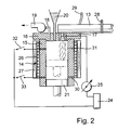
- a furnace 10 In a furnace 10 is a melt 11 of a metal alloy, for example AlSi 9, kept at a temperature above the Melting temperature of this alloy is.
- the oven 10 is vacuum tight closed and kept under vacuum by means of a suction device 12.
- the furnace 10 is connected to a crystallization container via a pouring line 13 14 connected.
- the crystallization container 14 consists of a cylinder 15 made of electrically non-conductive material that has a thermal conductivity between 0.20 and 1.5W / mk.
- the cylinder 15 is at the top closed a lid 16, which is also made of electrically non-conductive Material exists.
- the line 13 connects to the cover.
- the lid with an inlet piece 17 made of electrically conductive material connected.
- the inlet piece 17 has a conically widening Inlet opening.
- a suction line 18 connects to the cover 16, which is connected to a suction 19.
- the lid 16 is also with a filler neck 20 through which alloy in Powder form can be entered into the crystallization container 14.
- a piston 21, which also serves as the base of the crystallization container 14 consists of an electrically non-conductive material.
- the piston 21 is in an adjoining the crystallization container 14 Cylinder 22 guided, which is provided with a drain opening, not shown is.
- the cylinder 15 of the crystallization container 14 is in the area its bottom provided with an electrode 23.
- the inlet piece 17 is made of electrically conductive material. Between the electrode 23 and the inlet piece 17 is a voltage source 24 arranged, their tension and especially theirs Amperage is adjustable by means of an adjusting device 25.
- the crystallization container 14 is a preferably electrical heating device 26 assigned, which is preferably adjustable and which Crystallization container 14 heated to a preselectable temperature and keeps at that temperature. Furthermore, the crystallization tank 14 assigned a solenoid 27 with which inside the Cylinder 15 of the crystallization container 14 builds up a magnetic field is.
- the pouring channel 13 is equipped with a gate valve 28, via which the connection between the furnace 19 and the crystallization tank 14 can be released and locked.
- a feed line 29 via which protective gas Overpressure can be supplied, for example argon.
- melt 11 is first placed in the furnace 10 filled.
- the oven 10 is turned on by means of the suction 12 Vacuum brought from 0.5mbar to 3mbar.
- the crystallization tank 14 is heated to a temperature by means of the heating device 26, which 3% to 50% lower than the melting temperature of the alloy in question is.
- suction 19 creates a vacuum that is stronger than the vacuum in the furnace 10th
- the melt 11 is placed in the crystallization container 14 sucked in.
- protective gas is supplied via the line 29 fed. Due to the suction effect, alloy is also in powder form sucked in via the inlet connection 20. The powder is in the Melt enclosed and distributed.
- a voltage is applied to the electrode 23 and the inlet piece 17, so that a current flows in the beam of the melt, the size of which is less than 10A.
- a mixture to be as homogeneously dispersed as possible is obtained by means of the magnetic coil 27 inside the crystallization container 14 generates a magnetic field that leads to a radial Movement of the melt leads.
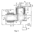
- the voltage source 24 is on two electrodes 30 and 31 of the cylinder 15 of the crystallization container 14 connected.
- the second connection is made to the pouring channel 13.
- the piston 21 moves during filling the melt continuously down, then one after the other the electrodes 30 and 31 are used, which with the piston movement can be switched on and off via switches 32 and 33.
- a storage or transport container 34 passed on, in which they are in the processed state is held.
- This container 34 is provided with a suction 35 so that a vacuum can be applied to it. He is with a heater 36 and a solenoid 37. As well it is equipped with an electrode 38.
- the two end walls of the Container 34 are formed by pistons 39 and 40.
- the container 34 can also be used for shaping.
- the thermokinetic sequence can be predicted with the nomogram shown in FIG. 4.
- the nomogram shown applies to the AlSi9Cu 3 alloy.
- the amount of powdery alloy that is added with a grain size of about 125 microns to about 400 microns is applied in percentages.
- the temperature difference ⁇ T in [C °] is the difference between the casting temperature and the melting temperature of the alloy. If an amount of powdery alloy is added which lies in the nomogram area A, this only brings about a reduction in the temperature of the melt. The melt is thus brought into a semi-solid state without the powdery particles forming nuclei. However, if an amount of powdery alloy is added so that the nomogram area B is reached, the powdery particles act as additional unmelted nuclei. If powdery particles are added in the nomogram area C, the two processes will take place side by side, ie a reduction in the overheating temperature and nucleation due to unmelted particles.
Landscapes
- Engineering & Computer Science (AREA)
- Mechanical Engineering (AREA)
- Chemical & Material Sciences (AREA)
- Materials Engineering (AREA)
- Metallurgy (AREA)
- Organic Chemistry (AREA)
- Manufacture Of Metal Powder And Suspensions Thereof (AREA)
- Manufacture And Refinement Of Metals (AREA)
- Treatment Of Steel In Its Molten State (AREA)
- Furnace Details (AREA)
- General Induction Heating (AREA)
- Joining Of Building Structures In Genera (AREA)
- Waste-Gas Treatment And Other Accessory Devices For Furnaces (AREA)
- Hard Magnetic Materials (AREA)
- Crystals, And After-Treatments Of Crystals (AREA)
Abstract
Description
Bei einer Vorrichtung zum Durchführen des Verfahrens wird ein Kristallisationsbehälter mit einem Einlass für die Schmelze und einem Einlass für Legierung in Pulverform vorgesehen, der eine Heizeinrichtung aufweist und der im Bereich seines Bodens und seines Einlasses mit an eine Spannungsquelle angelegten Elektroden versehen ist.
- Fig. 1
- zeigt eine erfindungsgemäße Vorrichtung im Schnitt in schematischer Darstellung, die direkt an einen Ofen angeschlossen ist,
- Fig. 2
- eine abgewandelte Ausführungsform einer erfindungsgemäßen Vorrichtung,
- Fig. 3
- eine erfindungsgemäße Vorrichtung mit einer Zusatzeinrichtung zur Übernahme der aufbereiteten Schmelze und
- Fig. 4
- ein Nomogramm zur Voraussage des thermokinetischen Ablaufs.
Claims (10)
- Verfahren zum Aufbereiten einer Schmelze einer Legierung für einen Gießvorgang, die in einen teilerstarrten Zustand gebracht wird und über ihr Volumen verteilte Kristallisationskeime enthält, dadurch gekennzeichnet, dass die Schmelze, die eine oberhalb der Schmelztemperatur der Legierung liegende Temperatur aufweist, in einen auf eine unterhalb der Schmelztemperatur liegende Temperatur beheizten Kristallisationsbehälter gebracht wird, dass dieser Schmelze in den Kristallisationsbehälter Legierung als Pulver zugegeben wird, und dass mittels elektrischer und/oder magnetischer Kräfte Schmelze und Pulver in dem Kristallisationsbehälter miteinander vermischt werden.
- Verfahren nach Anspruch 1, dadurch gekennzeichnet, dass die Schmelze als Strahl in den Kristallisationsbehälter eingebracht wird, der sich zwischen zwei Elektroden erstreckt, an die eine elektrische Spannung angelegt wird.
- Verfahren nach Anspruch 1 oder 2, dadurch gekennzeichnet, dass nach Einbringen der Schmelze zwischen der Schmelze und eine Elektrode ein Lichtbogen gezündet wird.
- Verfahren nach einem der Ansprüche 1 bis 3, dadurch gekennzeichnet, dass in dem Kristallisationsbehälter ein Magnetfeld gebildet wird.
- Verfahren nach einem der Ansprüche 1 bis 4, dadurch gekennzeichnet, dass die Schmelze in den unter Unterdruck gesetzten Kristallisationsbehälter eingesaugt wird.
- Verfahren nach einem der Ansprüche 1 bis 5, dadurch gekennzeichnet, dass die Schmelze unter Zufuhr von Schutzgas dem Kristallisationsbehälter zugeführt wird.
- Vorrichtung zum Durchführen des Verfahrens nach einem der Ansprüche 1 bis 6, dadurch gekennzeichnet, dass ein Kristallisationsbehälter (14) mit einem Einlass (17) für die Schmelze und einem Einlass (20) für Legierung in Pulverform vorgesehen ist, der eine Heizeinrichtung (26) aufweist und der im Bereich seines Bodens und seines Einlasses mit an eine Spannungsquelle (24) angelegten Elektroden (17, 23; 17, 30, 31) versehen ist.
- Vorrichtung nach Anspruch 7, dadurch gekennzeichnet, dass der Kristallisationsbehälter (14) an Mittel (19) zum Erzeugen von Unterdruck angeschlossen ist.
- Vorrichtung nach Anspruch 7 oder 8, dadurch gekennzeichnet, dass der Kristallisationsbehälter (14) mit Mitteln (27) zum Erzeugen eines in seinem Inneren wirksamen Magnetfeldes versehen ist.
- Vorrichtung nach einem der Ansprüche 7 bis 9, dadurch gekennzeichnet, dass der Kristallisationsbehälter (14) über eine Leitung (13) mit einem Ofen (10) verbunden ist, die mit einem Zuführanschluss (29) für Schutzgas versehen ist.
Priority Applications (1)
| Application Number | Priority Date | Filing Date | Title |
|---|---|---|---|
| SI200331339T SI1344589T1 (sl) | 2002-03-13 | 2003-02-21 | Postopek in priprava za pripravo taline zlitine za postopek ulivanja |
Applications Claiming Priority (2)
| Application Number | Priority Date | Filing Date | Title |
|---|---|---|---|
| DE10212349A DE10212349C1 (de) | 2002-03-13 | 2002-03-13 | Verfahren und Vorrichtung zum Aufbereiten einer Schmelze einer Legierung für einen Giessvorgang |
| DE10212349 | 2002-03-13 |
Publications (3)
| Publication Number | Publication Date |
|---|---|
| EP1344589A2 true EP1344589A2 (de) | 2003-09-17 |
| EP1344589A3 EP1344589A3 (de) | 2005-05-18 |
| EP1344589B1 EP1344589B1 (de) | 2008-06-04 |
Family
ID=7714155
Family Applications (1)
| Application Number | Title | Priority Date | Filing Date |
|---|---|---|---|
| EP03003899A Expired - Lifetime EP1344589B1 (de) | 2002-03-13 | 2003-02-21 | Verfahren und Vorrichtung zum Aufbereiten einer Schmelze einer Legierung für einen Giessvorgang |
Country Status (16)
| Country | Link |
|---|---|
| US (1) | US6988529B2 (de) |
| EP (1) | EP1344589B1 (de) |
| JP (1) | JP4541650B2 (de) |
| KR (1) | KR100995490B1 (de) |
| CN (1) | CN1275725C (de) |
| AT (1) | ATE397503T1 (de) |
| AU (1) | AU2003200990B2 (de) |
| BR (1) | BR0300491B1 (de) |
| CA (1) | CA2420931C (de) |
| DE (2) | DE10212349C1 (de) |
| DK (1) | DK1344589T3 (de) |
| ES (1) | ES2307838T3 (de) |
| MX (1) | MXPA03002089A (de) |
| NO (1) | NO20031112L (de) |
| PT (1) | PT1344589E (de) |
| SI (1) | SI1344589T1 (de) |
Families Citing this family (8)
| Publication number | Priority date | Publication date | Assignee | Title |
|---|---|---|---|---|
| US20050103461A1 (en) * | 2003-11-19 | 2005-05-19 | Tht Presses, Inc. | Process for generating a semi-solid slurry |
| CN102133629A (zh) * | 2011-03-01 | 2011-07-27 | 大连理工大学 | 一种轻合金电磁悬浮铸造装置和方法 |
| JP5991982B2 (ja) * | 2011-11-02 | 2016-09-14 | 大亜真空株式会社 | アーク溶解炉装置及び被溶解物のアーク溶解方法 |
| CN102794432A (zh) * | 2012-07-24 | 2012-11-28 | 江苏万里活塞轴瓦有限公司 | 铝合金半固态浆料制备装置 |
| JP6171216B2 (ja) * | 2013-05-09 | 2017-08-02 | 東芝機械株式会社 | 半凝固金属の製造装置、半凝固金属の製造方法及び半凝固金属を用いた成形方法 |
| CN109351916B (zh) * | 2018-07-31 | 2021-03-12 | 湖南人文科技学院 | 一种高硼合金的制备方法 |
| CN109261940A (zh) * | 2018-09-28 | 2019-01-25 | 平顶山学院 | 一种金属材料增材制造成型方法及装置 |
| CN110538587B (zh) * | 2019-09-12 | 2022-03-08 | 福建省鼎智新材料科技有限公司 | 一种基于气体搅拌的喷粉半固态制浆装置及其工作方法 |
Citations (6)
| Publication number | Priority date | Publication date | Assignee | Title |
|---|---|---|---|---|
| US4709746A (en) * | 1982-06-01 | 1987-12-01 | Alumax, Inc. | Process and apparatus for continuous slurry casting |
| JPH01306047A (ja) * | 1988-05-31 | 1989-12-11 | Nkk Corp | 半溶融金属の製造方法 |
| US5178204A (en) * | 1990-12-10 | 1993-01-12 | Kelly James E | Method and apparatus for rheocasting |
| JPH08290257A (ja) * | 1995-04-20 | 1996-11-05 | Mitsubishi Heavy Ind Ltd | 耐摩耗性アルミニウム合金鋳物及びその製造法 |
| WO1997012709A1 (en) * | 1995-10-05 | 1997-04-10 | Reynolds Wheels S.P.A | A method and device for the thixotropic casting of metal alloy products |
| DE10002670A1 (de) * | 2000-01-24 | 2001-08-02 | Ritter Aluminium Giesserei Gmb | Druckgießverfahren und Vorrichtung zu seiner Durchführung |
Family Cites Families (13)
| Publication number | Priority date | Publication date | Assignee | Title |
|---|---|---|---|---|
| US3813469A (en) * | 1973-04-09 | 1974-05-28 | Daido Steel Co Ltd | Method for heating vacuum degassing container |
| FR2275560A1 (fr) * | 1974-06-21 | 1976-01-16 | Anvar | Perfectionnements au degazage des metaux liquides, notamment de l'acier liquide, par jet sous vide |
| US4108643A (en) * | 1976-09-22 | 1978-08-22 | Massachusetts Institute Of Technology | Method for forming high fraction solid metal compositions and composition therefor |
| GB2037634B (en) * | 1978-11-27 | 1983-02-09 | Secretary Industry Brit | Casting thixotropic material |
| JPS5732859A (en) * | 1980-08-06 | 1982-02-22 | Nippon Steel Corp | Method and device for removing foreign substance from molten metal |
| JPS57127555A (en) * | 1981-01-29 | 1982-08-07 | Nippon Kokan Kk <Nkk> | Method for horizontal continuous casting of steel |
| US4482012A (en) * | 1982-06-01 | 1984-11-13 | International Telephone And Telegraph Corporation | Process and apparatus for continuous slurry casting |
| JPS63273553A (ja) * | 1987-04-30 | 1988-11-10 | Furukawa Alum Co Ltd | 中空ビレツトの製造方法および装置 |
| JPH01309766A (ja) * | 1988-06-09 | 1989-12-14 | Furukawa Electric Co Ltd:The | 鋳塊の製造方法とその装置 |
| US5379828A (en) * | 1990-12-10 | 1995-01-10 | Inland Steel Company | Apparatus and method for continuous casting of molten steel |
| US5494095A (en) * | 1992-04-08 | 1996-02-27 | Inland Steel Company | Apparatus for continuous casting of molten steel |
| JP3236508B2 (ja) * | 1996-06-25 | 2001-12-10 | トヨタ自動車株式会社 | 金属溶湯供給装置 |
| US5887640A (en) * | 1996-10-04 | 1999-03-30 | Semi-Solid Technologies Inc. | Apparatus and method for semi-solid material production |
-
2002
- 2002-03-13 DE DE10212349A patent/DE10212349C1/de not_active Expired - Fee Related
-
2003
- 2003-02-21 DK DK03003899T patent/DK1344589T3/da active
- 2003-02-21 AT AT03003899T patent/ATE397503T1/de active
- 2003-02-21 DE DE50309939T patent/DE50309939D1/de not_active Expired - Lifetime
- 2003-02-21 PT PT03003899T patent/PT1344589E/pt unknown
- 2003-02-21 SI SI200331339T patent/SI1344589T1/sl unknown
- 2003-02-21 EP EP03003899A patent/EP1344589B1/de not_active Expired - Lifetime
- 2003-02-21 ES ES03003899T patent/ES2307838T3/es not_active Expired - Lifetime
- 2003-03-05 CA CA2420931A patent/CA2420931C/en not_active Expired - Fee Related
- 2003-03-07 KR KR1020030014265A patent/KR100995490B1/ko active IP Right Grant
- 2003-03-07 JP JP2003061264A patent/JP4541650B2/ja not_active Expired - Fee Related
- 2003-03-11 MX MXPA03002089A patent/MXPA03002089A/es active IP Right Grant
- 2003-03-11 NO NO20031112A patent/NO20031112L/no not_active Application Discontinuation
- 2003-03-12 BR BRPI0300491-0A patent/BR0300491B1/pt not_active IP Right Cessation
- 2003-03-12 AU AU2003200990A patent/AU2003200990B2/en not_active Ceased
- 2003-03-12 US US10/386,587 patent/US6988529B2/en not_active Expired - Fee Related
- 2003-03-13 CN CNB031205216A patent/CN1275725C/zh not_active Expired - Fee Related
Patent Citations (6)
| Publication number | Priority date | Publication date | Assignee | Title |
|---|---|---|---|---|
| US4709746A (en) * | 1982-06-01 | 1987-12-01 | Alumax, Inc. | Process and apparatus for continuous slurry casting |
| JPH01306047A (ja) * | 1988-05-31 | 1989-12-11 | Nkk Corp | 半溶融金属の製造方法 |
| US5178204A (en) * | 1990-12-10 | 1993-01-12 | Kelly James E | Method and apparatus for rheocasting |
| JPH08290257A (ja) * | 1995-04-20 | 1996-11-05 | Mitsubishi Heavy Ind Ltd | 耐摩耗性アルミニウム合金鋳物及びその製造法 |
| WO1997012709A1 (en) * | 1995-10-05 | 1997-04-10 | Reynolds Wheels S.P.A | A method and device for the thixotropic casting of metal alloy products |
| DE10002670A1 (de) * | 2000-01-24 | 2001-08-02 | Ritter Aluminium Giesserei Gmb | Druckgießverfahren und Vorrichtung zu seiner Durchführung |
Non-Patent Citations (2)
| Title |
|---|
| PATENT ABSTRACTS OF JAPAN Bd. 014, Nr. 097 (M-0940), 22. Februar 1990 (1990-02-22) & JP 01 306047 A (NKK CORP), 11. Dezember 1989 (1989-12-11) * |
| PATENT ABSTRACTS OF JAPAN Bd. 1997, Nr. 03, 31. März 1997 (1997-03-31) & JP 08 290257 A (MITSUBISHI HEAVY IND LTD), 5. November 1996 (1996-11-05) * |
Also Published As
| Publication number | Publication date |
|---|---|
| JP2004025302A (ja) | 2004-01-29 |
| NO20031112L (no) | 2003-09-15 |
| US6988529B2 (en) | 2006-01-24 |
| MXPA03002089A (es) | 2004-08-11 |
| AU2003200990A1 (en) | 2003-10-02 |
| ATE397503T1 (de) | 2008-06-15 |
| EP1344589B1 (de) | 2008-06-04 |
| NO20031112D0 (no) | 2003-03-11 |
| SI1344589T1 (sl) | 2008-10-31 |
| CN1275725C (zh) | 2006-09-20 |
| BR0300491A (pt) | 2004-08-17 |
| BR0300491B1 (pt) | 2012-02-07 |
| ES2307838T3 (es) | 2008-12-01 |
| EP1344589A3 (de) | 2005-05-18 |
| CA2420931A1 (en) | 2003-09-13 |
| US20040003912A1 (en) | 2004-01-08 |
| JP4541650B2 (ja) | 2010-09-08 |
| AU2003200990B2 (en) | 2008-05-22 |
| KR100995490B1 (ko) | 2010-11-19 |
| CA2420931C (en) | 2011-05-03 |
| CN1443615A (zh) | 2003-09-24 |
| PT1344589E (pt) | 2008-08-13 |
| KR20030074297A (ko) | 2003-09-19 |
| DE50309939D1 (de) | 2008-07-17 |
| DK1344589T3 (da) | 2008-10-13 |
| DE10212349C1 (de) | 2003-08-28 |
Similar Documents
| Publication | Publication Date | Title |
|---|---|---|
| DE3018290A1 (de) | Verfahren und vorrichtung zum herstellen feinkoerniger gusstuecke | |
| DE4116073A1 (de) | Verfahren zum giessen von dentalmetallen | |
| DE69704200T2 (de) | Weiterverarbeitung durch elektroschlackeumschmelzen gereinigter metalle | |
| DE69224170T2 (de) | Verfahren und Vorrichtung zur Herstellung von homogenen Legierungen | |
| DE1558507A1 (de) | Neue Nickel-Legierung und Verfahren zu ihrer Herstellung | |
| EP1152854B1 (de) | Verwendung eines induktionstiegelofens für das niederdruckgiessen von gussstücken aus aluminium- und magnesiumlegierungen | |
| EP1344589B1 (de) | Verfahren und Vorrichtung zum Aufbereiten einer Schmelze einer Legierung für einen Giessvorgang | |
| DE2531571B2 (de) | Verfahren zum Einfahren von Zuschlagstoffen in Drahtform zu einer Metallschmelze und Einrichtung zur Durchführung des Verfahrens | |
| DE69614619T2 (de) | Schwebeschmelzenverfahren und Vorrichtung zum Schwebeschmelzen und Giessen | |
| WO2003074210A2 (de) | Verfahren und vorrichtung zur massgenauen feingussherstellung von bauteilen aus ne-metalllegierungen sowie ne-metalllegierungen zur durchführung des verfahrens | |
| DE1558159B2 (de) | Verfahren und vorrichtung zum vakuumgiessen von praezisions teilen aus metall mit hoechster reinheit | |
| DE69223950T2 (de) | Verfahren und Vorrichtung zur kontinuierlichen Herstellung von Metallmatrixverbundmaterial | |
| DE19852747A1 (de) | Verfahren zum Einschmelzen und Umschmelzen von Materialien zum Herstellen von homogenen Metallegierungen | |
| DE2501603C3 (de) | ||
| EP0280765B1 (de) | Verfahren und Vorrichtung zur Herstellung von Gusskörpern aus druckbehandelten Schmelzen aus Stahllegierungen | |
| WO2001055464A1 (de) | Druckgiessverfahren und vorrichtung zu seiner durchführung | |
| DE19504359C1 (de) | Verfahren zum Herstellen von Legierungen in einem induktiv beheizten Kaltwandtiegel | |
| EP1752552B1 (de) | Verfahren zum Herstellen von Vermikulargraphitguss | |
| DE3116792C2 (de) | Verfahren zur Gewinnung von Granalien aus einer Legierungsschmelze und Vorrichtung zur Durchführung desselben | |
| DE1483647C3 (de) | Beheizung für einen Schmelzofen in einer Vorrichtung zum Herstellen von stickstofflegierten Gußblöcken | |
| EP0819772B1 (de) | Verfahren zur Kornfeinerung oder Veredelung von Metallegierungen | |
| DE102021108933B4 (de) | Gießvorrichtung und Gießverfahren zur Herstellung von Metall-Matrix-Komposit-Werkstoffen | |
| DE102020005392A1 (de) | Verfahren zum Legieren von Metallen in einer Prozesskammer und Legierungsvorrichtung zur Durchführung eines solchen Verfahrens | |
| CH606452A5 (en) | Vacuum degassing liq metals before casting | |
| DE2508293A1 (de) | Verfahren zum druckgiessen von metallen mit hohem schmelzpunkt |
Legal Events
| Date | Code | Title | Description |
|---|---|---|---|
| PUAI | Public reference made under article 153(3) epc to a published international application that has entered the european phase |
Free format text: ORIGINAL CODE: 0009012 |
|
| AK | Designated contracting states |
Kind code of ref document: A2 Designated state(s): AT BE BG CH CY CZ DE DK EE ES FI FR GB GR HU IE IT LI LU MC NL PT SE SI SK TR |
|
| AX | Request for extension of the european patent |
Extension state: AL LT LV MK RO |
|
| PUAL | Search report despatched |
Free format text: ORIGINAL CODE: 0009013 |
|
| AK | Designated contracting states |
Kind code of ref document: A3 Designated state(s): AT BE BG CH CY CZ DE DK EE ES FI FR GB GR HU IE IT LI LU MC NL PT SE SI SK TR |
|
| AX | Request for extension of the european patent |
Extension state: AL LT LV MK RO |
|
| 17P | Request for examination filed |
Effective date: 20051110 |
|
| AKX | Designation fees paid |
Designated state(s): AT BE BG CH CY CZ DE DK EE ES FI FR GB GR HU IE IT LI LU MC NL PT SE SI SK TR |
|
| 17Q | First examination report despatched |
Effective date: 20061123 |
|
| GRAP | Despatch of communication of intention to grant a patent |
Free format text: ORIGINAL CODE: EPIDOSNIGR1 |
|
| GRAS | Grant fee paid |
Free format text: ORIGINAL CODE: EPIDOSNIGR3 |
|
| GRAA | (expected) grant |
Free format text: ORIGINAL CODE: 0009210 |
|
| AK | Designated contracting states |
Kind code of ref document: B1 Designated state(s): AT BE BG CH CY CZ DE DK EE ES FI FR GB GR HU IE IT LI LU MC NL PT SE SI SK TR |
|
| REG | Reference to a national code |
Ref country code: GB Ref legal event code: FG4D Free format text: NOT ENGLISH |
|
| REG | Reference to a national code |
Ref country code: CH Ref legal event code: EP |
|
| REF | Corresponds to: |
Ref document number: 50309939 Country of ref document: DE Date of ref document: 20080717 Kind code of ref document: P |
|
| REG | Reference to a national code |
Ref country code: PT Ref legal event code: SC4A Free format text: AVAILABILITY OF NATIONAL TRANSLATION Effective date: 20080801 |
|
| REG | Reference to a national code |
Ref country code: IE Ref legal event code: FG4D Free format text: LANGUAGE OF EP DOCUMENT: GERMAN |
|
| REG | Reference to a national code |
Ref country code: CH Ref legal event code: NV Representative=s name: ZIMMERLI, WAGNER & PARTNER AG |
|
| REG | Reference to a national code |
Ref country code: SE Ref legal event code: TRGR |
|
| REG | Reference to a national code |
Ref country code: GR Ref legal event code: EP Ref document number: 20080402089 Country of ref document: GR |
|
| REG | Reference to a national code |
Ref country code: DK Ref legal event code: T3 |
|
| REG | Reference to a national code |
Ref country code: ES Ref legal event code: FG2A Ref document number: 2307838 Country of ref document: ES Kind code of ref document: T3 |
|
| REG | Reference to a national code |
Ref country code: HU Ref legal event code: AG4A Ref document number: E003906 Country of ref document: HU |
|
| PLBE | No opposition filed within time limit |
Free format text: ORIGINAL CODE: 0009261 |
|
| STAA | Information on the status of an ep patent application or granted ep patent |
Free format text: STATUS: NO OPPOSITION FILED WITHIN TIME LIMIT |
|
| PG25 | Lapsed in a contracting state [announced via postgrant information from national office to epo] |
Ref country code: EE Free format text: LAPSE BECAUSE OF FAILURE TO SUBMIT A TRANSLATION OF THE DESCRIPTION OR TO PAY THE FEE WITHIN THE PRESCRIBED TIME-LIMIT Effective date: 20080604 Ref country code: BG Free format text: LAPSE BECAUSE OF FAILURE TO SUBMIT A TRANSLATION OF THE DESCRIPTION OR TO PAY THE FEE WITHIN THE PRESCRIBED TIME-LIMIT Effective date: 20080904 |
|
| 26N | No opposition filed |
Effective date: 20090305 |
|
| PG25 | Lapsed in a contracting state [announced via postgrant information from national office to epo] |
Ref country code: MC Free format text: LAPSE BECAUSE OF NON-PAYMENT OF DUE FEES Effective date: 20090228 |
|
| REG | Reference to a national code |
Ref country code: CH Ref legal event code: PFA Owner name: STERLING, EVGENIJ, DR. Free format text: STERLING, EVGENIJ, DR.#KATHARINENSTRASSE 62/1#73728 ESSLINGEN (DE) -TRANSFER TO- STERLING, EVGENIJ, DR.#KATHARINENSTRASSE 62/1#73728 ESSLINGEN (DE) |
|
| PGFP | Annual fee paid to national office [announced via postgrant information from national office to epo] |
Ref country code: CZ Payment date: 20100208 Year of fee payment: 8 Ref country code: DK Payment date: 20100222 Year of fee payment: 8 Ref country code: HU Payment date: 20100223 Year of fee payment: 8 Ref country code: IE Payment date: 20100219 Year of fee payment: 8 Ref country code: LU Payment date: 20100219 Year of fee payment: 8 Ref country code: PT Payment date: 20100212 Year of fee payment: 8 |
|
| PGFP | Annual fee paid to national office [announced via postgrant information from national office to epo] |
Ref country code: FI Payment date: 20100219 Year of fee payment: 8 Ref country code: SI Payment date: 20100209 Year of fee payment: 8 |
|
| PGFP | Annual fee paid to national office [announced via postgrant information from national office to epo] |
Ref country code: GB Payment date: 20100219 Year of fee payment: 8 |
|
| PGFP | Annual fee paid to national office [announced via postgrant information from national office to epo] |
Ref country code: SE Payment date: 20100215 Year of fee payment: 8 |
|
| PGFP | Annual fee paid to national office [announced via postgrant information from national office to epo] |
Ref country code: GR Payment date: 20100218 Year of fee payment: 8 |
|
| PGFP | Annual fee paid to national office [announced via postgrant information from national office to epo] |
Ref country code: SK Payment date: 20110311 Year of fee payment: 9 |
|
| PG25 | Lapsed in a contracting state [announced via postgrant information from national office to epo] |
Ref country code: CY Free format text: LAPSE BECAUSE OF FAILURE TO SUBMIT A TRANSLATION OF THE DESCRIPTION OR TO PAY THE FEE WITHIN THE PRESCRIBED TIME-LIMIT Effective date: 20080604 |
|
| REG | Reference to a national code |
Ref country code: DK Ref legal event code: EBP |
|
| REG | Reference to a national code |
Ref country code: SE Ref legal event code: EUG |
|
| GBPC | Gb: european patent ceased through non-payment of renewal fee |
Effective date: 20110221 |
|
| REG | Reference to a national code |
Ref country code: SI Ref legal event code: KO00 Effective date: 20110923 |
|
| PG25 | Lapsed in a contracting state [announced via postgrant information from national office to epo] |
Ref country code: PT Free format text: LAPSE BECAUSE OF NON-PAYMENT OF DUE FEES Effective date: 20110822 |
|
| REG | Reference to a national code |
Ref country code: IE Ref legal event code: MM4A |
|
| PG25 | Lapsed in a contracting state [announced via postgrant information from national office to epo] |
Ref country code: SI Free format text: LAPSE BECAUSE OF NON-PAYMENT OF DUE FEES Effective date: 20110222 Ref country code: CZ Free format text: LAPSE BECAUSE OF NON-PAYMENT OF DUE FEES Effective date: 20110221 Ref country code: FI Free format text: LAPSE BECAUSE OF NON-PAYMENT OF DUE FEES Effective date: 20110221 Ref country code: GR Free format text: LAPSE BECAUSE OF NON-PAYMENT OF DUE FEES Effective date: 20110902 |
|
| PG25 | Lapsed in a contracting state [announced via postgrant information from national office to epo] |
Ref country code: IE Free format text: LAPSE BECAUSE OF NON-PAYMENT OF DUE FEES Effective date: 20110221 |
|
| PG25 | Lapsed in a contracting state [announced via postgrant information from national office to epo] |
Ref country code: GB Free format text: LAPSE BECAUSE OF NON-PAYMENT OF DUE FEES Effective date: 20110221 |
|
| PGFP | Annual fee paid to national office [announced via postgrant information from national office to epo] |
Ref country code: CH Payment date: 20120221 Year of fee payment: 10 Ref country code: FR Payment date: 20120228 Year of fee payment: 10 |
|
| PGFP | Annual fee paid to national office [announced via postgrant information from national office to epo] |
Ref country code: TR Payment date: 20120221 Year of fee payment: 10 |
|
| PGFP | Annual fee paid to national office [announced via postgrant information from national office to epo] |
Ref country code: IT Payment date: 20120223 Year of fee payment: 10 Ref country code: BE Payment date: 20120221 Year of fee payment: 10 |
|
| PGFP | Annual fee paid to national office [announced via postgrant information from national office to epo] |
Ref country code: NL Payment date: 20120224 Year of fee payment: 10 |
|
| PGFP | Annual fee paid to national office [announced via postgrant information from national office to epo] |
Ref country code: AT Payment date: 20120220 Year of fee payment: 10 |
|
| PG25 | Lapsed in a contracting state [announced via postgrant information from national office to epo] |
Ref country code: LU Free format text: LAPSE BECAUSE OF NON-PAYMENT OF DUE FEES Effective date: 20110221 |
|
| PGFP | Annual fee paid to national office [announced via postgrant information from national office to epo] |
Ref country code: ES Payment date: 20120221 Year of fee payment: 10 |
|
| PG25 | Lapsed in a contracting state [announced via postgrant information from national office to epo] |
Ref country code: SE Free format text: LAPSE BECAUSE OF NON-PAYMENT OF DUE FEES Effective date: 20110222 |
|
| BERE | Be: lapsed |
Owner name: STERLING, EVGENIJ, DR. Effective date: 20130228 |
|
| REG | Reference to a national code |
Ref country code: NL Ref legal event code: V1 Effective date: 20130901 |
|
| REG | Reference to a national code |
Ref country code: CH Ref legal event code: PL |
|
| REG | Reference to a national code |
Ref country code: AT Ref legal event code: MM01 Ref document number: 397503 Country of ref document: AT Kind code of ref document: T Effective date: 20130228 |
|
| PG25 | Lapsed in a contracting state [announced via postgrant information from national office to epo] |
Ref country code: NL Free format text: LAPSE BECAUSE OF NON-PAYMENT OF DUE FEES Effective date: 20130901 Ref country code: CH Free format text: LAPSE BECAUSE OF NON-PAYMENT OF DUE FEES Effective date: 20130228 Ref country code: AT Free format text: LAPSE BECAUSE OF NON-PAYMENT OF DUE FEES Effective date: 20130228 Ref country code: LI Free format text: LAPSE BECAUSE OF NON-PAYMENT OF DUE FEES Effective date: 20130228 Ref country code: SK Free format text: LAPSE BECAUSE OF NON-PAYMENT OF DUE FEES Effective date: 20130221 |
|
| REG | Reference to a national code |
Ref country code: SK Ref legal event code: MM4A Ref document number: E 3859 Country of ref document: SK Effective date: 20130221 |
|
| REG | Reference to a national code |
Ref country code: FR Ref legal event code: ST Effective date: 20131031 |
|
| PG25 | Lapsed in a contracting state [announced via postgrant information from national office to epo] |
Ref country code: HU Free format text: LAPSE BECAUSE OF NON-PAYMENT OF DUE FEES Effective date: 20110222 Ref country code: IT Free format text: LAPSE BECAUSE OF NON-PAYMENT OF DUE FEES Effective date: 20130221 |
|
| PG25 | Lapsed in a contracting state [announced via postgrant information from national office to epo] |
Ref country code: FR Free format text: LAPSE BECAUSE OF NON-PAYMENT OF DUE FEES Effective date: 20130228 Ref country code: BE Free format text: LAPSE BECAUSE OF NON-PAYMENT OF DUE FEES Effective date: 20130228 |
|
| REG | Reference to a national code |
Ref country code: ES Ref legal event code: FD2A Effective date: 20140409 |
|
| PG25 | Lapsed in a contracting state [announced via postgrant information from national office to epo] |
Ref country code: ES Free format text: LAPSE BECAUSE OF NON-PAYMENT OF DUE FEES Effective date: 20130222 |
|
| PG25 | Lapsed in a contracting state [announced via postgrant information from national office to epo] |
Ref country code: TR Free format text: LAPSE BECAUSE OF NON-PAYMENT OF DUE FEES Effective date: 20130221 |
|
| PGFP | Annual fee paid to national office [announced via postgrant information from national office to epo] |
Ref country code: DE Payment date: 20170223 Year of fee payment: 15 |
|
| REG | Reference to a national code |
Ref country code: DE Ref legal event code: R119 Ref document number: 50309939 Country of ref document: DE |
|
| PG25 | Lapsed in a contracting state [announced via postgrant information from national office to epo] |
Ref country code: DE Free format text: LAPSE BECAUSE OF NON-PAYMENT OF DUE FEES Effective date: 20180901 |