EP1332921A1 - Befestigungsanordnung eines Lautsprechers an einem Verkleidungsteil eines Fahrzeuges - Google Patents
Befestigungsanordnung eines Lautsprechers an einem Verkleidungsteil eines Fahrzeuges Download PDFInfo
- Publication number
- EP1332921A1 EP1332921A1 EP02028831A EP02028831A EP1332921A1 EP 1332921 A1 EP1332921 A1 EP 1332921A1 EP 02028831 A EP02028831 A EP 02028831A EP 02028831 A EP02028831 A EP 02028831A EP 1332921 A1 EP1332921 A1 EP 1332921A1
- Authority
- EP
- European Patent Office
- Prior art keywords
- loudspeaker
- domes
- fastening
- holding part
- arrangement according
- Prior art date
- Legal status (The legal status is an assumption and is not a legal conclusion. Google has not performed a legal analysis and makes no representation as to the accuracy of the status listed.)
- Granted
Links
Images


Classifications
-
- B—PERFORMING OPERATIONS; TRANSPORTING
- B60—VEHICLES IN GENERAL
- B60R—VEHICLES, VEHICLE FITTINGS, OR VEHICLE PARTS, NOT OTHERWISE PROVIDED FOR
- B60R13/00—Elements for body-finishing, identifying, or decorating; Arrangements or adaptations for advertising purposes
- B60R13/02—Internal Trim mouldings ; Internal Ledges; Wall liners for passenger compartments; Roof liners
- B60R13/0237—Side or rear panels
- B60R13/025—Pillars; Roof rails
-
- B—PERFORMING OPERATIONS; TRANSPORTING
- B60—VEHICLES IN GENERAL
- B60R—VEHICLES, VEHICLE FITTINGS, OR VEHICLE PARTS, NOT OTHERWISE PROVIDED FOR
- B60R11/00—Arrangements for holding or mounting articles, not otherwise provided for
- B60R11/02—Arrangements for holding or mounting articles, not otherwise provided for for radio sets, television sets, telephones, or the like; Arrangement of controls thereof
- B60R11/0217—Arrangements for holding or mounting articles, not otherwise provided for for radio sets, television sets, telephones, or the like; Arrangement of controls thereof for loud-speakers
-
- B—PERFORMING OPERATIONS; TRANSPORTING
- B60—VEHICLES IN GENERAL
- B60R—VEHICLES, VEHICLE FITTINGS, OR VEHICLE PARTS, NOT OTHERWISE PROVIDED FOR
- B60R11/00—Arrangements for holding or mounting articles, not otherwise provided for
- B60R2011/0001—Arrangements for holding or mounting articles, not otherwise provided for characterised by position
- B60R2011/0003—Arrangements for holding or mounting articles, not otherwise provided for characterised by position inside the vehicle
- B60R2011/0019—Side or rear panels
- B60R2011/0022—Pillars
-
- B—PERFORMING OPERATIONS; TRANSPORTING
- B60—VEHICLES IN GENERAL
- B60R—VEHICLES, VEHICLE FITTINGS, OR VEHICLE PARTS, NOT OTHERWISE PROVIDED FOR
- B60R11/00—Arrangements for holding or mounting articles, not otherwise provided for
- B60R2011/0042—Arrangements for holding or mounting articles, not otherwise provided for characterised by mounting means
- B60R2011/0043—Arrangements for holding or mounting articles, not otherwise provided for characterised by mounting means for integrated articles, i.e. not substantially protruding from the surrounding parts
- B60R2011/0045—Arrangements for holding or mounting articles, not otherwise provided for characterised by mounting means for integrated articles, i.e. not substantially protruding from the surrounding parts with visible part, e.g. flush mounted
- B60R2011/0047—Arrangements for holding or mounting articles, not otherwise provided for characterised by mounting means for integrated articles, i.e. not substantially protruding from the surrounding parts with visible part, e.g. flush mounted using hidden fastening means
Definitions
- the invention relates to a mounting arrangement for a Loudspeaker cover covered speakers on a trim part of a Vehicle according to the preamble of claim 1.
- the object of the invention is to provide a mounting arrangement for a speaker to develop a trim part of a vehicle so that the speaker panel protrudes only minimally into the passenger compartment and that the replacement of a defective one Loudspeaker as easily as possible without dismantling the loudspeaker cover and holding part is feasible.
- the main advantages achieved with the invention are the fact that by flat speaker panel with molded domes and one speaker receiving holding part is created a speaker attachment that only protrudes insignificantly into the passenger compartment and by means of a simple one unproblematic speaker replacement without dismantling the speaker cover and Holding part is made possible.
- the loudspeaker cover and the holding part are simple inexpensive components to be manufactured.
- the complete speaker arrangement is easy to assemble. To dismantle the speaker you only need two Fastening screws are removed, whereas the speaker panel and that The holding part remains on the trim part.
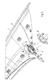
- Fig. 1 is in the passenger compartment 3 of a vehicle, not shown arranged trim part 1 shown, which in the embodiment by a Upright pillar trim 2 is formed.
- the trim part 1 is, for example, as Injection molded part made of a suitable plastic and has on the Passenger compartment 3 facing a grain or a decorative cover.
- the Fastening the trim part 1 on the adjacent structure, not shown of the vehicle is done in a conventional manner by clipping, screwing or the like.
- a Speaker arrangement 5 which consists of a speaker panel 6, a Holding part 7 and a speaker 8 is composed.
- the Speaker 8 upstream a central recess 9 formed as Sound passage opening serves.
- the recess 9 on the trim part 1 on all sides Outstanding loudspeaker cover 6 is from the front onto the passenger compartment 3 facing side of the trim part 1 and has at least some areas a grid-like structure with an outer circumferential closed frame (Fig. 1).
- the loudspeaker panel 6 is of flat construction towards the passenger compartment 3.
- the molded domes 11, 12 are approximately at right angles to that from the passenger compartment 3 visible surface 13 of the speaker panel 6 aligned and as a hollow cylinder 20th formed, the hollow cylinders 20 are closed to the passenger compartment 3.
- the holding part 7 is placed on the free ends 14 of the domes 11 and by means of Fixing screws 15 on the domes 11 fixed (Fig. 4).
- the Speaker 8 placed on the ring-shaped holding part 7 and on the domes 12 of the speaker panel 6 held in position by means of fastening screws 16 (Fig. 5).
- At least two domes 11 are preferably provided on the speaker panel 6 Connection with the holding part 7 and at least two further domes 12 for fastening the Speaker 8 provided.
- the two domes 11, 12 assigned to each other are formed diagonally opposite on the speaker panel 6 (see. Fig. 3). It can on the speaker panel 6, however, more or less than two domes Connection to the holding part 7 or for speaker attachment may be provided.
- the holding part 7 For the correct positioning of the holding part 7, it has a pot-shaped location trained receptacles 17 on the free ends 14 of the associated domes 11th reach around in sections (Fig. 4). Furthermore, the ring-shaped is supported Holding part 7 with a circumferential outer web 18 on the back of the Cladding part 1 from outside the recess 9. The web 18 points along its longitudinal extent on a different level.
- the loudspeaker 8 is interposed with a circumferential sealing body 19 the outer end face of the holding part 7 is placed and is by the Fixing screws 16 held in place.
- the mounting screws 15, 16 for the Loudspeaker 8 and the holding part 7 are each of the passenger compartment 3rd opposite side of the trim part 1 mounted and that Fastening screws 15, 16 are screwed into the hollow cylinders 20 of the domes 11, 12.
- the Hollow cylinders 20 of the domes 11 and 12 can either have an internal thread or thread-forming fastening screws 15, 16 are used, which in thread-free hollow cylinder 20 are screwed.
Abstract
Description
Es zeigt:
- Fig. 1
- in Explosionsdarstellung das Verkleidungsteil von vorne, die Lautsprecherblende, das Halteteil und den Lautsprecher,
- Fig. 2
- in weiterer Explosionsdarstellung das Verkleidungsteil von hinten mit aufgesetzter Lautsprecherblende, das Halteteil und den Lautsprecher,
- Fig. 3
- in weiterer Explosionsdarstellung das Verkleidungsteil von hinten mit montierter Lautsprecherblende aufgesetztem Halteteil und noch nicht montiertem Lautsprecher,
- Fig. 4
- einen Schnitt nach der Linie IV-IV der Fig. 3, wobei die Befestigung zwischen Lautsprecherblende und Halteteil dargestellt ist,
- Fig. 5
- einen Schnitt nach der Linie V-V der Fig. 3, der die Befestigung des Lautsprechers am Halteteil zeigt.
Claims (10)
- Befestigungsanordnung für einen durch eine Lautsprecherblende abgedeckten Lautsprecher an einem Verkleidungsteil eines Fahrzeuges, wobei das Verkleidungsteil benachbart des Lautsprechers eine Aussparung aufweist, die Lautsprecherblende und ein Halteteil durch Befestigungsschrauben miteinander verbunden sind und sich örtlich an gegenüberliegenden Seiten des Verkleidungsteiles abstützen, dadurch gekennzeichnet, daß an der Lautsprecherblende (6) mehrere mit Abstand zueinander angeordnete, von dieser abragende Dome (11, 12) vorgesehen sind, die durch am Verkleidungsteil (1) ausgebildete Durchbrüche (10) hindurchragen, wobei auf das das Verkleidungsteil (1) überragende freie Ende (14) jedes Domes (11, 12) entweder das Halteteil (7) oder der Lautsprecher (8) aufgesetzt und daran mittels einer eingedrehten Befestigungsschraube (15, 16) in Lage gehalten ist.
- Befestigungsanordnung nach Anspruch 1, dadurch gekennzeichnet, daß an der flachbauenden Lautsprecherblende (6) zumindest zwei Dome (11) zur Verbindung mit dem Halteteil (7) und zumindest weitere zwei Dome (12) zur Befestigung des Lautsprechers (8) ausgebildet sind.
- Befestigungsanordnung nach den Ansprüchen 1 und 2, dadurch gekennzeichnet, daß die zwei jeweils einander zugeordneten Dome (11 bzw. 12) diagonal gegenüberliegend an der Lautsprecherblende (6) angeordnet sind.
- Befestigungsanordnung nach den Ansprüchen 1 bis 3, dadurch gekennzeichnet, daß die angeformten Dome (11, 12) einstückig mit der Lautsprecherblende (6) ausgebildet sind.
- Befestigungsanordnung nach einem der vorangegangenen Ansprüche, dadurch gekennzeichnet, daß die Lautsprecherblende (6) durch ein Spritzgußteil aus einem geeignetem Kunststoff gebildet wird.
- Befestigungsanordnung nach Anspruch 1, dadurch gekennzeichnet, daß die Durchbrüche (10) am Verkleidungsteil (1) außerhalb und benachbart der zentralen Aussparung (9) vorgesehen sind.
- Befestigungsanordnung nach Anspruch 1, dadurch gekennzeichnet, daß zur lagerichtigen Positionierung des Halteteils (7) an diesem örtlich topfförmige Aufnahmen (17) ausgebildet sind, die die freien Enden (14) der zugeordneten Dome (11) der Lautsprecherblende (6) abschnittsweise umgreifen.
- Befestigungsanordnung nach einem der vorangegangenen Ansprüche, dadurch gekennzeichnet, daß das Halteteil (7) an zumindest zwei gegenüberliegend angeordneten Domen (11) der Lautsprecherblende (6) aufliegt und sich mit einem umlaufenden randseitigen Steg (18) an der Innenseite des Verkleidungsteiles (1) abstützt.
- Befestigungsvorrichtung nach einem der vorangegangenen Ansprüche, dadurch gekennzeichnet, daß der Lautsprecher (8) im Bereich seiner Befestigung an der Stirnseite der freien Enden der Dome (12) auflegt und mittels der Befestigungsschrauben (16) gegen die Dome (12) bzw. das Halteteil (7) gespannt wird, wobei zwischen Lautsprecher (8) und Halteteil (7) ein umlaufender Dichtkörper (19) zwischengeschaltet ist.
- Befestigungsanordnung nach einem der vorangegangenen Ansprüche, dadurch gekennzeichnet, daß die angespritzten Dome (11, 12) als Hohlzylinder (20) ausgebildet sind, die zum Fahrgastraum (3) hin geschlossen sind, wobei in die Hohlzylinder (20) von der Rückseite her die Befestigungsschrauben (15, 16) eingedreht sind.
Applications Claiming Priority (2)
| Application Number | Priority Date | Filing Date | Title |
|---|---|---|---|
| DE10204604 | 2002-02-05 | ||
| DE10204604A DE10204604C1 (de) | 2002-02-05 | 2002-02-05 | Befestigungsanordnung für einen durch eine Lautsprecherblende abgedeckten Lautsprecher an einem Verkleidungsteil eines Fahrzeuges |
Publications (2)
| Publication Number | Publication Date |
|---|---|
| EP1332921A1 true EP1332921A1 (de) | 2003-08-06 |
| EP1332921B1 EP1332921B1 (de) | 2006-03-22 |
Family
ID=7713692
Family Applications (1)
| Application Number | Title | Priority Date | Filing Date |
|---|---|---|---|
| EP02028831A Expired - Lifetime EP1332921B1 (de) | 2002-02-05 | 2002-12-21 | Befestigungsanordnung eines Lautsprechers an einem Verkleidungsteil eines Fahrzeuges |
Country Status (6)
| Country | Link |
|---|---|
| US (1) | US6918462B2 (de) |
| EP (1) | EP1332921B1 (de) |
| JP (1) | JP4210525B2 (de) |
| AT (1) | ATE320947T1 (de) |
| DE (2) | DE10204604C1 (de) |
| ES (1) | ES2257501T3 (de) |
Cited By (1)
| Publication number | Priority date | Publication date | Assignee | Title |
|---|---|---|---|---|
| DE102007016419A1 (de) * | 2007-04-05 | 2008-10-09 | Audi Ag | Vorrichtung zur Verbindung zweier Bauteile |
Families Citing this family (7)
| Publication number | Priority date | Publication date | Assignee | Title |
|---|---|---|---|---|
| US7364009B2 (en) * | 2004-04-30 | 2008-04-29 | Thomson Licensing | Loudspeaker mounting frame, loudspeaker and cabinet comprising a loudspeaker |
| US20050263342A1 (en) * | 2004-05-26 | 2005-12-01 | Meiloon Industrial Co., Ltd. | Speaker fixture assembly |
| JP2008072239A (ja) * | 2006-09-12 | 2008-03-27 | Sony Corp | 携帯電子機器 |
| JP4968083B2 (ja) * | 2008-01-22 | 2012-07-04 | スズキ株式会社 | 車両用スピーカーの取付構造 |
| DE102011051881B4 (de) * | 2011-07-15 | 2023-08-10 | Dr. Ing. H.C. F. Porsche Aktiengesellschaft | Befestigungselement |
| FR3067660B1 (fr) * | 2017-06-19 | 2019-11-22 | Renault S.A.S. | Grille de haut-parleur a tige anti-ejection |
| US20220348147A1 (en) * | 2021-04-30 | 2022-11-03 | Jvis-Usa, Llc | Low-Profile Panel Assembly for Providing Sound Within a Passenger Compartment of a Vehicle |
Citations (5)
| Publication number | Priority date | Publication date | Assignee | Title |
|---|---|---|---|---|
| US4993510A (en) * | 1989-04-22 | 1991-02-19 | Pioneer Electronic Corporation | Mobile speaker fixing device |
| JPH07251686A (ja) * | 1994-03-15 | 1995-10-03 | Kasai Kogyo Co Ltd | スピーカグリルの取付構造 |
| EP0769420A2 (de) * | 1995-10-18 | 1997-04-23 | Kabushiki Kaisha Kenwood | Lautsprecher-Montagebaugruppe für Kraftfahrzeuge |
| WO2000069687A1 (en) * | 1999-05-18 | 2000-11-23 | Magna Interior Systems, Inc. | Audio speaker mounting assembly for a vehicle panel |
| JP2001347896A (ja) * | 2000-06-05 | 2001-12-18 | Kasai Kogyo Co Ltd | ツイータユニットの取付構造 |
Family Cites Families (5)
| Publication number | Priority date | Publication date | Assignee | Title |
|---|---|---|---|---|
| DE2920836A1 (de) * | 1979-05-23 | 1980-11-27 | Eugen Otto Butz | Halterung fuer lautsprecher in kraftfahrzeugen |
| JPS60103987U (ja) * | 1983-12-20 | 1985-07-16 | パイオニア株式会社 | 車載用スピ−カ−等の取付機構 |
| US4712246A (en) * | 1984-12-14 | 1987-12-08 | Morrison Alberta J | Puppet speaker |
| DE3706918A1 (de) * | 1987-03-04 | 1988-09-15 | Opel Adam Ag | Halteelement fuer ein fahrzeug-ausruestungsteil und verfahren zu seiner montage |
| US5920039A (en) * | 1996-02-20 | 1999-07-06 | United Technologies Automotive, Inc. | Speaker support bar and sound chamber above vehicle headliner |
-
2002
- 2002-02-05 DE DE10204604A patent/DE10204604C1/de not_active Expired - Fee Related
- 2002-12-21 ES ES02028831T patent/ES2257501T3/es not_active Expired - Lifetime
- 2002-12-21 EP EP02028831A patent/EP1332921B1/de not_active Expired - Lifetime
- 2002-12-21 AT AT02028831T patent/ATE320947T1/de not_active IP Right Cessation
- 2002-12-21 DE DE50206132T patent/DE50206132D1/de not_active Expired - Lifetime
-
2003
- 2003-01-17 JP JP2003009585A patent/JP4210525B2/ja not_active Expired - Fee Related
- 2003-02-05 US US10/358,259 patent/US6918462B2/en not_active Expired - Fee Related
Patent Citations (5)
| Publication number | Priority date | Publication date | Assignee | Title |
|---|---|---|---|---|
| US4993510A (en) * | 1989-04-22 | 1991-02-19 | Pioneer Electronic Corporation | Mobile speaker fixing device |
| JPH07251686A (ja) * | 1994-03-15 | 1995-10-03 | Kasai Kogyo Co Ltd | スピーカグリルの取付構造 |
| EP0769420A2 (de) * | 1995-10-18 | 1997-04-23 | Kabushiki Kaisha Kenwood | Lautsprecher-Montagebaugruppe für Kraftfahrzeuge |
| WO2000069687A1 (en) * | 1999-05-18 | 2000-11-23 | Magna Interior Systems, Inc. | Audio speaker mounting assembly for a vehicle panel |
| JP2001347896A (ja) * | 2000-06-05 | 2001-12-18 | Kasai Kogyo Co Ltd | ツイータユニットの取付構造 |
Non-Patent Citations (2)
| Title |
|---|
| PATENT ABSTRACTS OF JAPAN vol. 1996, no. 02 29 February 1996 (1996-02-29) * |
| PATENT ABSTRACTS OF JAPAN vol. 2002, no. 04 4 August 2002 (2002-08-04) * |
Cited By (1)
| Publication number | Priority date | Publication date | Assignee | Title |
|---|---|---|---|---|
| DE102007016419A1 (de) * | 2007-04-05 | 2008-10-09 | Audi Ag | Vorrichtung zur Verbindung zweier Bauteile |
Also Published As
| Publication number | Publication date |
|---|---|
| US20030146042A1 (en) | 2003-08-07 |
| ATE320947T1 (de) | 2006-04-15 |
| ES2257501T3 (es) | 2006-08-01 |
| DE50206132D1 (de) | 2006-05-11 |
| EP1332921B1 (de) | 2006-03-22 |
| DE10204604C1 (de) | 2003-04-24 |
| US6918462B2 (en) | 2005-07-19 |
| JP2003237488A (ja) | 2003-08-27 |
| JP4210525B2 (ja) | 2009-01-21 |
Similar Documents
| Publication | Publication Date | Title |
|---|---|---|
| DE102013217939B4 (de) | Vorrichtung zur Halterung und Justierung eines Sensors | |
| DE4341619C1 (de) | Dachreling für Fahrzeuge | |
| EP1332921A1 (de) | Befestigungsanordnung eines Lautsprechers an einem Verkleidungsteil eines Fahrzeuges | |
| DE4413626A1 (de) | Gehäuse für Überkopf-Lautsprecher in Kraftfahrzeugen | |
| EP1347135A2 (de) | Kraftfahrzeug mit einer Öffnung, die von einem schwenkbaren Bauteil, insbesondere einer Heckklappe, verschliessbar ist | |
| DE1192936B (de) | Aus Kunststoff oder aehnlichem Werkstoff, wie Gummi, bestehende Karosserieteile, wieKotfluegel, Tuerblenden, Stirnwaende u. dgl. | |
| WO1998013229A1 (de) | Vorrichtung zum befestigen eines scheinwerfers oder einer leuchte an einem fahrzeugteil | |
| DE10227237A1 (de) | Vorrichtung zum Toleranzausgleich für Montageverbindungen und Verbindungselement mit einer derartigen Vorrichtung | |
| DE102011051429A1 (de) | Befestigungseinrichtung | |
| DE102010016365A1 (de) | Vorrichtung zum Befestigen eines Armaturenbrettes an einem Fahrzeug | |
| DE202004002682U1 (de) | Vorrichtung zur Verriegelung eines schwenkbaren Karosserieteils an der Karosserie eines Kraftfahrzeuges | |
| DE102006058226A1 (de) | Baugruppe zur fahrzeugseitigen Befestigung eines Gurtschlosses | |
| DE102015001605B3 (de) | Kraftfahrzeug | |
| DE102018112061B4 (de) | Blendenvorrichtung für den Innenraum eines Fahrzeugs und Verfahren zur Montage einer Blendenvorrichtung | |
| DE2945001C2 (de) | Vorrichtung zur Befestigung einer Halbsäule unterhalb eines Waschtisches | |
| DE10208042A1 (de) | Türgriff | |
| DE102018100759B4 (de) | Karosserieanordnung für ein Kraftfahrzeug | |
| EP2425066B1 (de) | Trennwandsystem für den Innenausbau | |
| DE3925774A1 (de) | Vorrichtung zur halterung von kotfluegeln | |
| DE102017003975A1 (de) | Vorrichtung zum Befestigen eines Körpers an einer Fläche, und System zum Halten eines Profils | |
| WO2006048239A1 (de) | Aufprallweiches karosseriebauelement, insbesondere fronthaube in einem kraftfahrzeug | |
| DE102007033730A1 (de) | Verkleidungsaussparung für einen externen Seitenaufprall-Airbag | |
| CH682582A5 (de) | Bedienungshebeleinheit für Fenster, insbesondere Dreh-Kipp-Fenster. | |
| EP0887564A1 (de) | Formteil für Kfz-Innenausstattung, insbesondere Abdeckung oder Blende | |
| DE102020104096A1 (de) | Punkthalter für flache Elemente |
Legal Events
| Date | Code | Title | Description |
|---|---|---|---|
| PUAI | Public reference made under article 153(3) epc to a published international application that has entered the european phase |
Free format text: ORIGINAL CODE: 0009012 |
|
| AK | Designated contracting states |
Designated state(s): AT BE BG CH CY CZ DE DK EE ES FI FR GB GR IE IT LI LU MC NL PT SE SI SK TR |
|
| AX | Request for extension of the european patent |
Extension state: AL LT LV MK RO |
|
| 17P | Request for examination filed |
Effective date: 20040206 |
|
| AKX | Designation fees paid |
Designated state(s): AT BE BG CH CY CZ DE DK EE ES FI FR GB GR IE IT LI LU MC NL PT SE SI SK TR |
|
| 17Q | First examination report despatched |
Effective date: 20041001 |
|
| GRAP | Despatch of communication of intention to grant a patent |
Free format text: ORIGINAL CODE: EPIDOSNIGR1 |
|
| GRAS | Grant fee paid |
Free format text: ORIGINAL CODE: EPIDOSNIGR3 |
|
| GRAA | (expected) grant |
Free format text: ORIGINAL CODE: 0009210 |
|
| AK | Designated contracting states |
Kind code of ref document: B1 Designated state(s): AT BE BG CH CY CZ DE DK EE ES FI FR GB GR IE IT LI LU MC NL PT SE SI SK TR |
|
| PG25 | Lapsed in a contracting state [announced via postgrant information from national office to epo] |
Ref country code: SI Free format text: LAPSE BECAUSE OF FAILURE TO SUBMIT A TRANSLATION OF THE DESCRIPTION OR TO PAY THE FEE WITHIN THE PRESCRIBED TIME-LIMIT Effective date: 20060322 Ref country code: SK Free format text: LAPSE BECAUSE OF FAILURE TO SUBMIT A TRANSLATION OF THE DESCRIPTION OR TO PAY THE FEE WITHIN THE PRESCRIBED TIME-LIMIT Effective date: 20060322 Ref country code: IE Free format text: LAPSE BECAUSE OF FAILURE TO SUBMIT A TRANSLATION OF THE DESCRIPTION OR TO PAY THE FEE WITHIN THE PRESCRIBED TIME-LIMIT Effective date: 20060322 Ref country code: NL Free format text: LAPSE BECAUSE OF FAILURE TO SUBMIT A TRANSLATION OF THE DESCRIPTION OR TO PAY THE FEE WITHIN THE PRESCRIBED TIME-LIMIT Effective date: 20060322 |
|
| REG | Reference to a national code |
Ref country code: GB Ref legal event code: FG4D Free format text: NOT ENGLISH |
|
| REG | Reference to a national code |
Ref country code: CH Ref legal event code: EP |
|
| REG | Reference to a national code |
Ref country code: SE Ref legal event code: TRGR |
|
| REG | Reference to a national code |
Ref country code: IE Ref legal event code: FG4D Free format text: LANGUAGE OF EP DOCUMENT: GERMAN |
|
| REF | Corresponds to: |
Ref document number: 50206132 Country of ref document: DE Date of ref document: 20060511 Kind code of ref document: P |
|
| GBT | Gb: translation of ep patent filed (gb section 77(6)(a)/1977) |
Effective date: 20060517 |
|
| PG25 | Lapsed in a contracting state [announced via postgrant information from national office to epo] |
Ref country code: DK Free format text: LAPSE BECAUSE OF FAILURE TO SUBMIT A TRANSLATION OF THE DESCRIPTION OR TO PAY THE FEE WITHIN THE PRESCRIBED TIME-LIMIT Effective date: 20060622 Ref country code: BG Free format text: LAPSE BECAUSE OF FAILURE TO SUBMIT A TRANSLATION OF THE DESCRIPTION OR TO PAY THE FEE WITHIN THE PRESCRIBED TIME-LIMIT Effective date: 20060622 |
|
| REG | Reference to a national code |
Ref country code: ES Ref legal event code: FG2A Ref document number: 2257501 Country of ref document: ES Kind code of ref document: T3 |
|
| PG25 | Lapsed in a contracting state [announced via postgrant information from national office to epo] |
Ref country code: PT Free format text: LAPSE BECAUSE OF FAILURE TO SUBMIT A TRANSLATION OF THE DESCRIPTION OR TO PAY THE FEE WITHIN THE PRESCRIBED TIME-LIMIT Effective date: 20060822 |
|
| NLV1 | Nl: lapsed or annulled due to failure to fulfill the requirements of art. 29p and 29m of the patents act | ||
| ET | Fr: translation filed | ||
| REG | Reference to a national code |
Ref country code: IE Ref legal event code: FD4D |
|
| PG25 | Lapsed in a contracting state [announced via postgrant information from national office to epo] |
Ref country code: MC Free format text: LAPSE BECAUSE OF NON-PAYMENT OF DUE FEES Effective date: 20061231 Ref country code: LI Free format text: LAPSE BECAUSE OF NON-PAYMENT OF DUE FEES Effective date: 20061231 Ref country code: BE Free format text: LAPSE BECAUSE OF NON-PAYMENT OF DUE FEES Effective date: 20061231 Ref country code: CH Free format text: LAPSE BECAUSE OF NON-PAYMENT OF DUE FEES Effective date: 20061231 |
|
| PLBE | No opposition filed within time limit |
Free format text: ORIGINAL CODE: 0009261 |
|
| STAA | Information on the status of an ep patent application or granted ep patent |
Free format text: STATUS: NO OPPOSITION FILED WITHIN TIME LIMIT |
|
| 26N | No opposition filed |
Effective date: 20061227 |
|
| REG | Reference to a national code |
Ref country code: CH Ref legal event code: PL |
|
| BERE | Be: lapsed |
Owner name: DR.ING. H.C.F. PORSCHE A.G. Effective date: 20061231 |
|
| PGFP | Annual fee paid to national office [announced via postgrant information from national office to epo] |
Ref country code: AT Payment date: 20071224 Year of fee payment: 6 |
|
| PGFP | Annual fee paid to national office [announced via postgrant information from national office to epo] |
Ref country code: SE Payment date: 20071213 Year of fee payment: 6 |
|
| PG25 | Lapsed in a contracting state [announced via postgrant information from national office to epo] |
Ref country code: CZ Free format text: LAPSE BECAUSE OF FAILURE TO SUBMIT A TRANSLATION OF THE DESCRIPTION OR TO PAY THE FEE WITHIN THE PRESCRIBED TIME-LIMIT Effective date: 20060322 Ref country code: GR Free format text: LAPSE BECAUSE OF FAILURE TO SUBMIT A TRANSLATION OF THE DESCRIPTION OR TO PAY THE FEE WITHIN THE PRESCRIBED TIME-LIMIT Effective date: 20060623 |
|
| PG25 | Lapsed in a contracting state [announced via postgrant information from national office to epo] |
Ref country code: FI Free format text: LAPSE BECAUSE OF FAILURE TO SUBMIT A TRANSLATION OF THE DESCRIPTION OR TO PAY THE FEE WITHIN THE PRESCRIBED TIME-LIMIT Effective date: 20060322 Ref country code: EE Free format text: LAPSE BECAUSE OF FAILURE TO SUBMIT A TRANSLATION OF THE DESCRIPTION OR TO PAY THE FEE WITHIN THE PRESCRIBED TIME-LIMIT Effective date: 20060322 |
|
| PG25 | Lapsed in a contracting state [announced via postgrant information from national office to epo] |
Ref country code: TR Free format text: LAPSE BECAUSE OF FAILURE TO SUBMIT A TRANSLATION OF THE DESCRIPTION OR TO PAY THE FEE WITHIN THE PRESCRIBED TIME-LIMIT Effective date: 20060322 Ref country code: LU Free format text: LAPSE BECAUSE OF NON-PAYMENT OF DUE FEES Effective date: 20061221 |
|
| PG25 | Lapsed in a contracting state [announced via postgrant information from national office to epo] |
Ref country code: CY Free format text: LAPSE BECAUSE OF FAILURE TO SUBMIT A TRANSLATION OF THE DESCRIPTION OR TO PAY THE FEE WITHIN THE PRESCRIBED TIME-LIMIT Effective date: 20060322 |
|
| PGFP | Annual fee paid to national office [announced via postgrant information from national office to epo] |
Ref country code: ES Payment date: 20090127 Year of fee payment: 7 |
|
| REG | Reference to a national code |
Ref country code: FR Ref legal event code: TP |
|
| EUG | Se: european patent has lapsed | ||
| PG25 | Lapsed in a contracting state [announced via postgrant information from national office to epo] |
Ref country code: AT Free format text: LAPSE BECAUSE OF NON-PAYMENT OF DUE FEES Effective date: 20081221 |
|
| REG | Reference to a national code |
Ref country code: FR Ref legal event code: CD |
|
| PG25 | Lapsed in a contracting state [announced via postgrant information from national office to epo] |
Ref country code: SE Free format text: LAPSE BECAUSE OF NON-PAYMENT OF DUE FEES Effective date: 20081222 |
|
| REG | Reference to a national code |
Ref country code: FR Ref legal event code: TP |
|
| REG | Reference to a national code |
Ref country code: ES Ref legal event code: FD2A Effective date: 20110330 |
|
| REG | Reference to a national code |
Ref country code: GB Ref legal event code: 732E Free format text: REGISTERED BETWEEN 20110310 AND 20110316 |
|
| REG | Reference to a national code |
Ref country code: GB Ref legal event code: 732E Free format text: REGISTERED BETWEEN 20110331 AND 20110406 |
|
| PG25 | Lapsed in a contracting state [announced via postgrant information from national office to epo] |
Ref country code: ES Free format text: LAPSE BECAUSE OF NON-PAYMENT OF DUE FEES Effective date: 20110317 |
|
| PG25 | Lapsed in a contracting state [announced via postgrant information from national office to epo] |
Ref country code: ES Free format text: LAPSE BECAUSE OF NON-PAYMENT OF DUE FEES Effective date: 20091222 |
|
| REG | Reference to a national code |
Ref country code: FR Ref legal event code: PLFP Year of fee payment: 14 |
|
| PGFP | Annual fee paid to national office [announced via postgrant information from national office to epo] |
Ref country code: GB Payment date: 20151221 Year of fee payment: 14 Ref country code: DE Payment date: 20151207 Year of fee payment: 14 |
|
| PGFP | Annual fee paid to national office [announced via postgrant information from national office to epo] |
Ref country code: FR Payment date: 20151221 Year of fee payment: 14 |
|
| PGFP | Annual fee paid to national office [announced via postgrant information from national office to epo] |
Ref country code: IT Payment date: 20151228 Year of fee payment: 14 |
|
| REG | Reference to a national code |
Ref country code: DE Ref legal event code: R119 Ref document number: 50206132 Country of ref document: DE |
|
| GBPC | Gb: european patent ceased through non-payment of renewal fee |
Effective date: 20161221 |
|
| REG | Reference to a national code |
Ref country code: FR Ref legal event code: ST Effective date: 20170831 |
|
| PG25 | Lapsed in a contracting state [announced via postgrant information from national office to epo] |
Ref country code: FR Free format text: LAPSE BECAUSE OF NON-PAYMENT OF DUE FEES Effective date: 20170102 Ref country code: IT Free format text: LAPSE BECAUSE OF NON-PAYMENT OF DUE FEES Effective date: 20161221 |
|
| PG25 | Lapsed in a contracting state [announced via postgrant information from national office to epo] |
Ref country code: GB Free format text: LAPSE BECAUSE OF NON-PAYMENT OF DUE FEES Effective date: 20161221 Ref country code: DE Free format text: LAPSE BECAUSE OF NON-PAYMENT OF DUE FEES Effective date: 20170701 |