EP1319545A1 - Dispositif de remplissage pour véhicules diesel - Google Patents
Dispositif de remplissage pour véhicules diesel Download PDFInfo
- Publication number
- EP1319545A1 EP1319545A1 EP01129821A EP01129821A EP1319545A1 EP 1319545 A1 EP1319545 A1 EP 1319545A1 EP 01129821 A EP01129821 A EP 01129821A EP 01129821 A EP01129821 A EP 01129821A EP 1319545 A1 EP1319545 A1 EP 1319545A1
- Authority
- EP
- European Patent Office
- Prior art keywords
- filler neck
- filling
- parts
- container
- diameter
- Prior art date
- Legal status (The legal status is an assumption and is not a legal conclusion. Google has not performed a legal analysis and makes no representation as to the accuracy of the status listed.)
- Granted
Links
Images


Classifications
-
- B—PERFORMING OPERATIONS; TRANSPORTING
- B60—VEHICLES IN GENERAL
- B60K—ARRANGEMENT OR MOUNTING OF PROPULSION UNITS OR OF TRANSMISSIONS IN VEHICLES; ARRANGEMENT OR MOUNTING OF PLURAL DIVERSE PRIME-MOVERS IN VEHICLES; AUXILIARY DRIVES FOR VEHICLES; INSTRUMENTATION OR DASHBOARDS FOR VEHICLES; ARRANGEMENTS IN CONNECTION WITH COOLING, AIR INTAKE, GAS EXHAUST OR FUEL SUPPLY OF PROPULSION UNITS IN VEHICLES
- B60K15/00—Arrangement in connection with fuel supply of combustion engines or other fuel consuming energy converters, e.g. fuel cells; Mounting or construction of fuel tanks
- B60K15/03—Fuel tanks
- B60K15/04—Tank inlets
- B60K2015/0458—Details of the tank inlet
- B60K2015/0483—Means to inhibit the introduction of too small or too big filler nozzles
Definitions
- the invention relates to a in a filler neck of a container with a large Device that can be used in diameter as a barrier for filling the container through a filling pipe of small diameter from the side into the Filler neck protruding, the cross-sectional tapering to one Predeterminable diameter, displaceable Security device and the use of a tubular insert for such a device.
- DE 196 39 825 A1 describes a lead free barrier for use in one Tank filler neck known.
- This lead freeze block has a receptacle for the Pipe a liquid fuel nozzle and a detachable one Cross-sectional rejuvenation that is effective in a lead exemption Has a diameter that is larger than the pipe of a lead nozzle and is smaller than the pipe for a fuel nozzle for diesel or leaded fuel, and which in a released state forms a lead / diesel assembly and this releases an effective diameter that is larger than the pipe Fuel nozzle for diesel or leaded fuel, the Cross-sectional taper is part of a lever system that between the Lead release and the lead / diesel assembly is pivotable.
- This Swiveling is triggered by a tool, in particular a pen and is designed to be one and the same Device can be used for motor vehicles, which when mounting the The fuel tank's decision requires whether this tank is for a Vehicle powered by unleaded fuel, leaded fuel or Diesel fuel is to be used.
- the locking position is therefore once during the assembly of the fuel tank with the lead-free insert or another use and then remains in the motor vehicle.
- a filler neck with a pipe seal is known from WO 90/14244 the filler neck except for a vent after filling with fuel hermetically sealed.
- This seal is as a funnel-shaped plastic or Rubber sleeve formed, with the funnel at the tapered end a ring spring is kept closed.
- a lock for certain diameters of filling pipes is therefore not connected, but only a gas-tight closure of the nozzle after the Filling.
- the invention is therefore based on the problem of a device for Use in the filler neck of the container, especially one Propose a motor vehicle that accidental filling a for Diesel tank provided with another fuel prevents, assuming that the filling pipe for diesel a larger Diameter than the filler pipe for other types of fuel.
- the solution is that in a first variant one into one Filler neck with large diameter of a container can be used Device is proposed as a lock for filling the container through a filling tube of small diameter and the one from the side in protruding the filler neck, the cross-sectional tapering to one Predeterminable diameter, displaceable Security device, characterized in that the Safety device consisting of several on the inner wall of the filler neck parts that cannot be locked by means of a flexible holder, which together form a tapered section in the filler neck, its dimension towards the filling opening towards the filling pipe with a large diameter and to the inside of the container, the small diameter fill pipe corresponds and the section in a transverse lock for the insertion depth of the filling tube with a small diameter ends, the parts on the flexible Bracket are pivotally attached.
- the bracket is annular and there are two or more parts arranged, the legs, which are flying to the inside of the Extend container and have at their end projections, which to Extend the center axis of the filler neck.
- This shape of the tapered Section in combination with the bracket and the transverse lock in Projection shape is one of several embodiments such device according to the invention.
- the parts of the securing device are preferably elastic and form in relieved the tapered section.
- the parts are also structurally not elastic or essentially trained inelastic and with each other by a resilient element couple so that these parts under tension the tapered Form the section of a filling pipe against the large diameter appropriate spring tension can be opened.
- the resilient element as a coil spring or as elastic ring made of rubber or metal, e.g. the ring can too in the manner of a coil spring made of metal or elastic plastic exist or it will, for example, a spring steel or equivalent Wire used.
- the bracket itself and the parts are in one piece trained and used as such in the nozzle, preferably as Materials plastics or resilient metals are used.
- the tapered section practically consists of resilient extensions the bracket, bent up by the filling pipe of larger diameter while a small diameter fill pipe does not bend these parts can, since this holder at its tapered end the diameter of the small filling tube corresponds and can therefore not be inserted further than that transverse lock or corresponding projections on the legs allow.
- the holder can also be used as a separate part, e.g. as annular torsion spring to be formed, which at the same time on the circumference of Filler neck or is fixed to the wall.
- the transverse lock or Protrusions provided with an elastic plate that is in one piece or made of consists of several parts, one in the relieved state essentially Form a closed circular surface and consist of elastic material.
- This plate is preferably attached under the lock or the projections, for example by gluing, welding or screwing.
- Such an elastic plate is bent or swung away by the correct filling device, a large diameter filling pipe together with the parts, so that the filling pipe can also penetrate the elastic plate, even if the restoring force of the elastic plate has to be overcome.
- this filler pipe is stopped by the lock or the projections, and when attempting to trigger the fuel nozzle, the elastic plate creates a back pressure, as a result of which the commercial fuel nozzles with their automatic switch-off block the flow for large mass flows.
- this property of the plate can be used in combination with the automatic switch-off to fill in small amounts of unleaded petrol, despite the locking device.
- the invention proposes that in the generic device, the safety device as in the Filler neck protruding spring steel leg is formed on the or is attached outside the wall of the filler neck, with a first Elbow tapered the cross section in the filler neck to the small diameter with a second bow on the same or a different leg as transverse lock is formed for the insertion depth of the filling tube, wherein the lock can also be provided with an annular plate.
- the spring steel can fill the filler neck in its cross section reduce that in addition to the first bend of the spring steel only one fill tube small diameter can be pushed past, but which then the transverse barrier occurs and / or the filling of unwanted Fuel or unwanted amount of fuel using the second sheet and / or the annular plate prevented.
- the first arch of the spring steel is through the larger filler tube bent or shifted elastically, which at the same time the transversal lock through the second arch of the spring steel leg is formed, opens.
- a tubular insert in the event that, for example, gasoline or other additives are to be added to the diesel container during winter operation.
- the insert can be used in one of the devices described above and can be used accordingly if it has a wall whose thickness has the difference in thickness between the large and small diameters of the filling tubes described, and then also fills the diesel container through the inside diameter of the insert to allow a gasoline nozzle.
- the insert can also be designed in such a way that it is previously placed on the gasoline nozzle or arranged there and thus simulates a filling pipe of large diameter.
- the locking device with the filling tube can be small Diameter also by e.g. predeterminable mechanical device Right-left movement or helical movement can be unlocked.
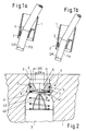
- Figures 1a and 1b show for a container 1, e.g. a fuel tank one Vehicle, a filler neck 3 with a cross-sectional taper 2, which has an opening through which a filling pipe FG with a large diameter DG or a filling tube FK of small diameter DK extends through to the Fill container 1.
- the filling pipe FG belongs to a fuel nozzle, for example for diesel fuel and the filling pipe FK to a nozzle for lead-free Fuel.
- the diameter DG corresponds to the container 1 with the opening on the cross-sectional taper 2 to be used as intended FG filling pipe for diesel fuel.
- Figure 1b shows that according to the state of the Technology of the container 1 can also be filled with a filling tube FK, wherein filling this container 1 with unleaded fuel, e.g. with the nozzle with filling tube FK can lead to considerable damage.
- FIG. 2 therefore shows a first variant of the first solution of the invention, in which for the container 1 with the filler neck 3 in a cross-sectional taper 2 a safety device 4 is used, which fills the container 1 with to exclude a filling device FK.
- the securing device 4 has via a bracket 5, with which it - in a manner not shown - on the Inner wall of the filler neck 3 is attached.
- the securing device 4 contains at least two, preferably three or more, legs 7, which are L-shaped are formed and together a tapered section 6 in Enclose filler neck 3. This tapered section has on the fill side, i.e.
- leg extension 8 of leg 7 which extends towards the center of the filler neck.
- the legs 7 are held by a coil spring 42, the Position by a wire cage 43 and a collar 41 on the legs 7 is determined.
- the legs 7 pivot about the bracket 5 when overcoming the spring force of the coil spring 42 in the Swivel space 9 that a passage corresponding to the diameter DG in the Filler neck 3 becomes free and, analogously to FIG Filler neck 3 can be inserted to fill the container 1.
- Figure 3a shows a device with the same effect as in Figure 2.
- Der Container 1 has a filler neck 3 and a cross-sectional taper 2.
- a safety device 40 is attached to the filler neck 3 and is made of an elastic retaining ring 5 and legs 7, which on the elastic Retaining ring are pivotally coupled. The attachment of the retaining ring 7 on the filler neck or in the cross-sectional taper 2 is not shown.
- the legs 7 have an L-shaped acting as a lock Extension 8, which is a reach through a filling tube FK with small Do not allow diameter DK.
- the legs 7 in turn form Filler neck or its cross-sectional taper a tapered Section 6, as is clear from Figure 3a.
- Figure 3 b shows the interaction of a security device 40 with a FG tube with large diameter DG.
- the legs 7 tilt with the Leg extensions 8 to the outside, up to the guide parts 71 of the After pivoting around the retaining ring 5, rest leg 7 on the filling pipe FG.
- the retaining ring 5, e.g. consisting of a wire spring, and the legs 7, in this case also the designed as a spring retaining ring 5 are in the pivot space 9 of the Displaced container 1 so that the filling tube FG finds inlet to the container.
- FIGS. 4 a, 4 b show one of the prior art according to Figures 1 a, b in essentially identical structure, however, the area of Cross-sectional taper 2 in the filler neck 3 with a safety device provided which here from the legs 70 and the lock 80 for filling pipes FK exists.
- the legs 70 and the lock 80 are from the same here Material manufactured, such as the filler neck or the container part 1 itself, e.g. a plastic part, but the legs 70 form with the lock 80 integral part with the filler neck or its cross-sectional taper 2.
- the tapered section is in section according to FIG. 4 a, which is a Sectional position IV - IV in Figure 4 b clearly shows.
- FIG. 4 a which is a Sectional position IV - IV in Figure 4 b clearly shows.
- the top view to the situation at the filler neck according to Figure 4 b, the central axis A is clearly shown that the leg 70 in the direction project onto the central axis A of the filler neck and into the locks
- FIGS. 5 a, b, c show a situation similar to FIGS. 4 a, 4 b, however, four legs 70 with four locks 80 are shown here, in contrast to the three legs 70 with a corresponding number of locks 80 according to the Figures 4 a, 4 b.
- Figure 5 b can be seen how a filling pipe FG with Diameter DG in the device according to the invention with the Security device can be easily introduced.
- the Leg 70 in the filler neck more precisely in the area of the cross-sectional taper or the tapered section 6 spread so that the locks 80th at the same time swivel away with the legs 70 and the filling pipe FG let through.
- the nozzle with filling pipe FG with the help of Filling tube catches FR, as usual from the driver, on the edge of the filler neck or container 1 and the automatic function of the nozzle can be set. This is then another without user intervention Filling the container, which usually takes minutes, is possible. For in the event that such engagement does not occur, the driver will additionally attentive that something is wrong with the refueling process corresponds to normal procedure. Such a situation the user will find if, according to FIG. 5 c, a small filling pipe FK with the diameter DK in a container 1 with the device according to the invention, represented here by the legs 70 of the tapered section and the locks 80, finds. In this case, the filling tube catches FR can not be on the edge of the Lock the container and the user becomes aware that this is a situation is given, which makes it impossible for him to continue the filling tube FK Insert container 1 because it is blocked at the locks 80.
- FIGS a, b, c an embodiment of the Invention according to Figures 5 a - c additionally with one, the filling of fuel-obstructing plate 10, which is shown in FIGS a, b, c is shown.
- a plate e.g. made of a resilient metal schematically shown as plate 10, which by means of a plate holder 11 in not shown attached to the container 1 or in the filler neck and closes the opening 21 below the legs 70 or the barriers 80 Container.
- This plate 10 made of spring steel or a stable, resilient
- plastic can be used as intended through a filling pipe FG are pressed on after the legs 70, as previously in FIG. 5 b shown, were pivoted or bent.
- FIG. 6b plastic can be used as intended through a filling pipe FG are pressed on after the legs 70, as previously in FIG. 5 b shown, were pivoted or bent.
- FIG. 7 a again shows a situation according to FIG. 5 a, but with the A one-piece plate from inside the container below the locks 80 Plastic or rubber, reference numeral 100, is arranged.
- Arrow VII assigns a view according to Figure 7 d with an alternative embodiment of the Plate 100.
- the plate consists of four segments 110, each under the locks 80 of the legs 70 are glued and essentially except for a small passage in the middle, which at the same time a ventilation of the Container enables a closure of the filler neck.
- the design is a lock according to the invention in one way possible, as has already been described for Figures 5 and 6.
- Figure 7 b shows how segments 110 open elastically when filling pipe FG with the correct diameter is used to fill the container 1.
- a small filling pipe FK is also shown in FIG. 7 c hindered by the legs 70 or locks 80, further into the container penetrate.
- the plate 100 prevents, in the manner already described, that fuel is filled into the tank in this position.
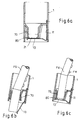
- FIGS. 8 a-c can also be used.
- a container 1 with filler neck 3, which has a cross-sectional taper 2 receives a securing device 400 consisting of two components.
- a steel spring is fastened to the container or filler neck 3 with a holder, for example a screw 405.
- the securing device 400 also consists of a further spring steel as a leg 402, which is also fastened to the filler neck with a holder 405 and has an arc 409 which thus also has a tapering section 6 within the cross-sectional taper 2 of the filler neck forms.
- the spring steel bracket can be bent up elastically by a filling tube FG (not shown) in the region of the bend 409.
- the leg or spring steel bracket 402 preferably has a projection 411 at the end, which serves to support the plate 410. It is pressed out of its position at the same time as the arch 409 through the filling pipe, so that the second arch 407/410 can also clear the way through the tapered section 6.
- the spring steel bracket 410 is pushed away in order to clear the filler neck or the access to the interior of the container for the filling pipe.
- the bottom 410 of the spring steel element can also be designed in the form of a plate, as was shown with other plates with reference to FIGS. 6 a and 7 a.
- the spring steel bracket is replaced by a plastic leg 403 with projection 406, which is mounted on the holder 5 as described above in an elastically resilient and swiveling manner or forms an integrally molded part on the holder.
- 8c shows a variant in which a leg 404 made of plastic has a projection 408 which supports the plate 410.
- a plurality of such brackets can also be used.
- FIG. 9a shows a sixth embodiment 500 of the device, partly in section, of which the tapered section 6 in Fig. 9b enlarged and pivoted by 90 ° is shown.
- Some parts have the same reference numbers as one or two Apostrophe additives; these indicate different positions of the parts Introduction of a filling pipe FG into the nozzle.
- the filler neck 3 has a funnel-shaped cross-sectional taper 2 that is formed by the bracket 5 with the leg or legs 505.
- Another part or flexible resilient leg 501 is on the Stuck attached, the bow 507 in a plate designed as a lock 510 ends.
- A is placed on or molded onto the plate arcuate element 509, which in a recess 503 on the leg 505 Finds space.
- the leg 505 has a projection 506 Support of the plate 510 on its nose 508 in the rest position according to FIG. 9a.
- the open position of the filler neck when the filler pipe is inserted shows the plate 510 "with element 509".
- FIG. 9b The function of the device is clear in FIG. 9b. If that is dashed FG shown large diameter is inserted, it reaches in Section 6 the element 509 blocking the passage Insert pushes the filling tube FG into position 509 ', it gives way by the resulting force F (arrow) into the recess 503 and takes thereby the plate to position 510 'and at the same time bends the leg 501 in the same direction.
- the integrally formed on the spring steel bracket 11, 401, 501 Bow 407, 507 also as a swivel joint with a return spring be designed.
- FIG. 11 shows a seventh embodiment of the invention.
- the Cross-sectional taper 2 of the filler neck 3 are one or more resilient Bracket 600 with first arches 609 to form the tapered section 6 and integrally formed second arches 610 arranged.
- the bows have the same function as previously described.
- the stirrups 600 are with hooks fixed in holes 605.
- the recesses 607 of the cross-sectional taper 2 provide space for the deformation of the first arches 609 when the Filling tube FG, wherein the arches 609 have a curved spatial shape, see above that the second arches 610 can move sideways and so the passage clear for filling pipes FG.
- an insert 12 a toroid with an outside diameter DG and an inside diameter DK use which is either inserted into the device according to the invention and so then a nozzle with filling pipe FK through the interior of the ring 12 can be inserted, or such an insert 12 is used to on the filling pipe FK to be put on, so that practically a filling pipe FG obtained, which can be used as provided in the invention.
Landscapes
- Engineering & Computer Science (AREA)
- Life Sciences & Earth Sciences (AREA)
- Sustainable Development (AREA)
- Sustainable Energy (AREA)
- Chemical & Material Sciences (AREA)
- Combustion & Propulsion (AREA)
- Transportation (AREA)
- Mechanical Engineering (AREA)
- Cooling, Air Intake And Gas Exhaust, And Fuel Tank Arrangements In Propulsion Units (AREA)
Priority Applications (2)
| Application Number | Priority Date | Filing Date | Title |
|---|---|---|---|
| DE50112972T DE50112972D1 (de) | 2001-12-14 | 2001-12-14 | Vorrichtung zur Betankung von Dieselfahrzeugen |
| EP01129821A EP1319545B2 (fr) | 2001-12-14 | 2001-12-14 | Dispositif de remplissage pour véhicules diesel |
Applications Claiming Priority (1)
| Application Number | Priority Date | Filing Date | Title |
|---|---|---|---|
| EP01129821A EP1319545B2 (fr) | 2001-12-14 | 2001-12-14 | Dispositif de remplissage pour véhicules diesel |
Publications (3)
| Publication Number | Publication Date |
|---|---|
| EP1319545A1 true EP1319545A1 (fr) | 2003-06-18 |
| EP1319545B1 EP1319545B1 (fr) | 2007-09-05 |
| EP1319545B2 EP1319545B2 (fr) | 2010-08-25 |
Family
ID=8179546
Family Applications (1)
| Application Number | Title | Priority Date | Filing Date |
|---|---|---|---|
| EP01129821A Expired - Lifetime EP1319545B2 (fr) | 2001-12-14 | 2001-12-14 | Dispositif de remplissage pour véhicules diesel |
Country Status (2)
| Country | Link |
|---|---|
| EP (1) | EP1319545B2 (fr) |
| DE (1) | DE50112972D1 (fr) |
Cited By (34)
| Publication number | Priority date | Publication date | Assignee | Title |
|---|---|---|---|---|
| GB2391544A (en) * | 2002-08-01 | 2004-02-11 | Stephen Nicholl | Fuel tank filler neck having a blocking member |
| WO2004101305A1 (fr) * | 2003-05-09 | 2004-11-25 | Advance Technology Venture Ltd. | Tubulure de remplissage de reservoir |
| EP1625964A2 (fr) * | 2004-08-11 | 2006-02-15 | Stant Manufacturing Inc. | Dispositif anti-insertion pour pistolet de distribution de carburant |
| EP1627761A2 (fr) * | 2004-08-11 | 2006-02-22 | Stant Manufacturing Inc. | Dispositif anti-insertion pour pistolet de distribution de carburant |
| US7011121B2 (en) | 2004-04-08 | 2006-03-14 | I.T.W. De France | End piece for a fuel filler pipe of a vehicle |
| EP1642761A1 (fr) * | 2004-09-30 | 2006-04-05 | Stant Manufacturing Inc. | Protection contre pistolet de distribution de carburant |
| WO2006066294A1 (fr) * | 2004-12-20 | 2006-06-29 | Tesma Motoren- Und Getriebetechnik Gmbh | Tubulure de remplissage sans couvercle pour le reservoir d'un vehicule automobile |
| EP1690726A1 (fr) * | 2005-02-10 | 2006-08-16 | Gerdes GmbH | Embout de remplissage d'un réservoir de carburant sans bouchon |
| DE102005047459A1 (de) * | 2005-09-30 | 2006-08-24 | Alfmeier Präzision AG Baugruppen und Systemlösungen | Tankeinfüllstutzen für ein Diesel-Kraftfahrzeug |
| WO2007012488A1 (fr) * | 2005-07-27 | 2007-02-01 | Reutter Gmbh | Dispositif evitant toute erreur de ravitaillement |
| WO2007013863A2 (fr) * | 2005-07-27 | 2007-02-01 | Janez Alic | Accessoire d'entree pour la protection d'un contenant de carburant diesel |
| GB2431634A (en) * | 2005-10-25 | 2007-05-02 | Rhys Holdaway | Device to prevent incorrect fuelling of a vehicle |
| DE102005053793A1 (de) * | 2005-11-09 | 2007-05-10 | Alfmeier Präzision AG Baugruppen und Systemlösungen | Tankeinfüllstutzen für Diesel-Kraftfahrzeuge |
| WO2007091079A1 (fr) * | 2006-02-09 | 2007-08-16 | Mark Wells | Dispositif permettant d'empecher l'introduction complète d'un premier conduit dans un deuxieme conduit |
| WO2007104762A1 (fr) * | 2006-03-15 | 2007-09-20 | Inergy Automotive Systems Research (Société Anonyme) | Inhibiteur pour pistolet de distribution de carburant |
| FR2898550A1 (fr) * | 2006-03-15 | 2007-09-21 | Inergy Automotive Systems Res | Systeme de securite pour tubulure de remplissage |
| US7293586B2 (en) | 2005-06-22 | 2007-11-13 | Stant Manufacturing Inc. | Fuel-dispensing nozzle inhibitor |
| WO2008059228A1 (fr) * | 2006-11-13 | 2008-05-22 | Diesel International Limited | Orifice de remplissage amélioré |
| WO2008127916A1 (fr) * | 2007-04-16 | 2008-10-23 | Illinois Tool Works Inc. | Système de blocage sélectif d'une buse de carburant |
| WO2009007385A1 (fr) * | 2007-07-11 | 2009-01-15 | Inergy Automotive Systems Research (Societe Anonyme) | Système pour remplir un réservoir |
| WO2009022140A2 (fr) * | 2007-08-15 | 2009-02-19 | Diesel Do Nicely Limited | Dispositif destiné à être raccordé à l'entrée de fluide d'un réservoir de carburant |
| GB2456178A (en) * | 2008-01-05 | 2009-07-08 | Neill Mills | A diesel fuel tank safety insert |
| JP2009234312A (ja) * | 2008-03-26 | 2009-10-15 | Fuji Heavy Ind Ltd | 誤給油防止装置 |
| WO2009135954A2 (fr) | 2008-05-09 | 2009-11-12 | Gerdes Gmbh | Raccord pour tubulure de remplissage |
| US7665493B2 (en) | 2005-02-10 | 2010-02-23 | Stant Manufacturing Inc. | Fuel-dispensing nozzle inhibitor |
| WO2010023810A1 (fr) * | 2008-08-25 | 2010-03-04 | 株式会社ニフコ | Dispositif permettant d'éviter les erreurs de ravitaillement en essence |
| DE102009007866A1 (de) | 2009-02-06 | 2010-08-12 | Daimler Ag | Kraftfahrzeugtank mit einer Sicherungseinrichtung |
| EP1319545B2 (fr) † | 2001-12-14 | 2010-08-25 | Ford Global Technologies, LLC | Dispositif de remplissage pour véhicules diesel |
| DE112009002053T5 (de) | 2008-09-04 | 2011-06-22 | I.T.W. De France | Kraftstoffeinfüllrohr-Endstück für Fahrzeuge |
| US7967041B2 (en) | 2007-07-19 | 2011-06-28 | Stant Usa Corp. | Fuel-dispensing nozzle inhibitor |
| WO2012034643A1 (fr) * | 2010-09-16 | 2012-03-22 | Kautex Textron Gmbh & Co. Kg | Goulot de remplissage destiné au réservoir de carburant d'un véhicule à moteur |
| EP2562024A1 (fr) * | 2011-08-25 | 2013-02-27 | Gerdes GmbH | Fermeture de manchon de citerne pouvant être fermée sans couvercle |
| WO2013050486A1 (fr) * | 2011-10-04 | 2013-04-11 | Tecinnovation Gmbh | Dispositif de sécurite conçu pour un contenant |
| US10000117B2 (en) | 2012-02-17 | 2018-06-19 | Stant Usa Corp. | Filler neck closure assembly |
Families Citing this family (3)
| Publication number | Priority date | Publication date | Assignee | Title |
|---|---|---|---|---|
| DE102007063338A1 (de) | 2007-12-20 | 2009-04-16 | Alfmeier Präzision AG Baugruppen und Systemlösungen | Vorrichtung, Reservekanister und Bordwerkzeug zum Betanken eines Dieselfahrzeugs |
| DE102008009252A1 (de) | 2008-02-15 | 2009-08-20 | Konstantinos Tsiberidis | Fehlbetankungsverhinderungsvorrichtung, insbesondere für Fahrzeuge mit Dieselmotor |
| CN113911995A (zh) * | 2020-07-09 | 2022-01-11 | 上海浦东新区天佑市政有限公司 | 一种无人驾驶智能扫地车自动加水机构 |
Citations (5)
| Publication number | Priority date | Publication date | Assignee | Title |
|---|---|---|---|---|
| US3880317A (en) * | 1973-03-02 | 1975-04-29 | Ford Motor Co | Inlet insert |
| DE3641274A1 (de) * | 1985-12-11 | 1987-06-19 | Volkswagen Ag | Betankungssperre fuer den einfuellstutzen eines tanks, insbesondere eines kraftstofftanks |
| GB2230765A (en) * | 1989-04-15 | 1990-10-31 | Ford Motor Co | Insert for restricting access to fuel tank |
| WO1990014244A1 (fr) | 1989-05-17 | 1990-11-29 | Vernay Laboratories, Inc. | Joint d'etancheite pour conduit de remplissage de reservoir de carburant |
| DE19639825A1 (de) | 1995-10-06 | 1997-04-10 | Volkswagen Ag | Bleifreisperre |
Family Cites Families (6)
| Publication number | Priority date | Publication date | Assignee | Title |
|---|---|---|---|---|
| US4034784A (en) † | 1974-08-14 | 1977-07-12 | General Motors Corporation | Filler neck to inhibit use of leaded fuel |
| DE8528368U1 (de) † | 1985-10-04 | 1985-11-28 | Blau KG, 4018 Langenfeld | Reduziereinsatz für einen Tankfüll-Stutzen |
| FR2741014B1 (fr) † | 1995-11-15 | 1998-01-09 | Peugeot | Dispositif detrompeur pour le conduit de remplissage en carburant d'un vehicule automobile |
| US6302169B1 (en) † | 2000-09-13 | 2001-10-16 | Peter C. Pulos | Diesel fuel nozzle restrictor |
| DE10126207A1 (de) † | 2001-05-30 | 2003-01-16 | Bayerische Motoren Werke Ag | Kraftfahrzeug-Kraftstofftank mit einem Einfüllstutzen zur Aufnahme einer Zapfpistole für Dieselkraftstoff |
| EP1319545B2 (fr) † | 2001-12-14 | 2010-08-25 | Ford Global Technologies, LLC | Dispositif de remplissage pour véhicules diesel |
-
2001
- 2001-12-14 EP EP01129821A patent/EP1319545B2/fr not_active Expired - Lifetime
- 2001-12-14 DE DE50112972T patent/DE50112972D1/de not_active Expired - Lifetime
Patent Citations (5)
| Publication number | Priority date | Publication date | Assignee | Title |
|---|---|---|---|---|
| US3880317A (en) * | 1973-03-02 | 1975-04-29 | Ford Motor Co | Inlet insert |
| DE3641274A1 (de) * | 1985-12-11 | 1987-06-19 | Volkswagen Ag | Betankungssperre fuer den einfuellstutzen eines tanks, insbesondere eines kraftstofftanks |
| GB2230765A (en) * | 1989-04-15 | 1990-10-31 | Ford Motor Co | Insert for restricting access to fuel tank |
| WO1990014244A1 (fr) | 1989-05-17 | 1990-11-29 | Vernay Laboratories, Inc. | Joint d'etancheite pour conduit de remplissage de reservoir de carburant |
| DE19639825A1 (de) | 1995-10-06 | 1997-04-10 | Volkswagen Ag | Bleifreisperre |
Cited By (58)
| Publication number | Priority date | Publication date | Assignee | Title |
|---|---|---|---|---|
| EP1319545B2 (fr) † | 2001-12-14 | 2010-08-25 | Ford Global Technologies, LLC | Dispositif de remplissage pour véhicules diesel |
| GB2391544B (en) * | 2002-08-01 | 2005-12-07 | Stephen Nicholl | Filler neck |
| GB2391544A (en) * | 2002-08-01 | 2004-02-11 | Stephen Nicholl | Fuel tank filler neck having a blocking member |
| WO2004101305A1 (fr) * | 2003-05-09 | 2004-11-25 | Advance Technology Venture Ltd. | Tubulure de remplissage de reservoir |
| US7011121B2 (en) | 2004-04-08 | 2006-03-14 | I.T.W. De France | End piece for a fuel filler pipe of a vehicle |
| EP1625964A3 (fr) * | 2004-08-11 | 2006-12-27 | Stant Manufacturing Inc. | Dispositif anti-insertion pour pistolet de distribution de carburant |
| EP1625964A2 (fr) * | 2004-08-11 | 2006-02-15 | Stant Manufacturing Inc. | Dispositif anti-insertion pour pistolet de distribution de carburant |
| EP1627761A2 (fr) * | 2004-08-11 | 2006-02-22 | Stant Manufacturing Inc. | Dispositif anti-insertion pour pistolet de distribution de carburant |
| EP1627761A3 (fr) * | 2004-08-11 | 2006-12-27 | Stant Manufacturing Inc. | Dispositif anti-insertion pour pistolet de distribution de carburant |
| EP1642761A1 (fr) * | 2004-09-30 | 2006-04-05 | Stant Manufacturing Inc. | Protection contre pistolet de distribution de carburant |
| US7302977B2 (en) | 2004-09-30 | 2007-12-04 | Stant Manufacturing Inc. | Fuel-dispensing nozzle inhibitor |
| WO2006066294A1 (fr) * | 2004-12-20 | 2006-06-29 | Tesma Motoren- Und Getriebetechnik Gmbh | Tubulure de remplissage sans couvercle pour le reservoir d'un vehicule automobile |
| US20080271816A1 (en) * | 2005-02-10 | 2008-11-06 | Ralf Gerdes | Cap-Free Neck End For A Filler Neck |
| JP2008529879A (ja) * | 2005-02-10 | 2008-08-07 | ゲルデス ゲーエムベーハー | 給油接続パイプ用の無蓋の接続パイプ終端部 |
| US9452858B2 (en) | 2005-02-10 | 2016-09-27 | Gerdes Gmbh | Cap-free neck end for a filler neck |
| US9725203B2 (en) | 2005-02-10 | 2017-08-08 | Gerdes Gmbh | Cap-free neck end for a filler neck |
| EP1690726A1 (fr) * | 2005-02-10 | 2006-08-16 | Gerdes GmbH | Embout de remplissage d'un réservoir de carburant sans bouchon |
| WO2006084908A2 (fr) | 2005-02-10 | 2006-08-17 | Kusenberg, Andrea | Bordure de tubulure de remplissage sans couvercle |
| US8746298B2 (en) | 2005-02-10 | 2014-06-10 | Gerdes Gmbh | Cap-free neck end for a filler neck |
| WO2006084908A3 (fr) * | 2005-02-10 | 2006-11-30 | Kusenberg Andrea | Bordure de tubulure de remplissage sans couvercle |
| CN101119869B (zh) * | 2005-02-10 | 2011-08-17 | 格德斯股份有限公司 | 用于加油管的可无盖封闭的接管端 |
| US7665493B2 (en) | 2005-02-10 | 2010-02-23 | Stant Manufacturing Inc. | Fuel-dispensing nozzle inhibitor |
| EP2666656A1 (fr) * | 2005-02-10 | 2013-11-27 | Gerdes GmbH | Tubulure de remplissage d'un réservoir d'un véhicule automobile |
| US7293586B2 (en) | 2005-06-22 | 2007-11-13 | Stant Manufacturing Inc. | Fuel-dispensing nozzle inhibitor |
| WO2007013863A3 (fr) * | 2005-07-27 | 2007-03-15 | Janez Alic | Accessoire d'entree pour la protection d'un contenant de carburant diesel |
| WO2007013863A2 (fr) * | 2005-07-27 | 2007-02-01 | Janez Alic | Accessoire d'entree pour la protection d'un contenant de carburant diesel |
| WO2007012488A1 (fr) * | 2005-07-27 | 2007-02-01 | Reutter Gmbh | Dispositif evitant toute erreur de ravitaillement |
| DE102005047459A1 (de) * | 2005-09-30 | 2006-08-24 | Alfmeier Präzision AG Baugruppen und Systemlösungen | Tankeinfüllstutzen für ein Diesel-Kraftfahrzeug |
| GB2431634A (en) * | 2005-10-25 | 2007-05-02 | Rhys Holdaway | Device to prevent incorrect fuelling of a vehicle |
| DE102005053793A1 (de) * | 2005-11-09 | 2007-05-10 | Alfmeier Präzision AG Baugruppen und Systemlösungen | Tankeinfüllstutzen für Diesel-Kraftfahrzeuge |
| DE102005053793B4 (de) * | 2005-11-09 | 2009-12-31 | Alfmeier Präzision AG Baugruppen und Systemlösungen | Tankeinfüllstutzen für Diesel-Kraftfahrzeuge |
| WO2007091079A1 (fr) * | 2006-02-09 | 2007-08-16 | Mark Wells | Dispositif permettant d'empecher l'introduction complète d'un premier conduit dans un deuxieme conduit |
| FR2898550A1 (fr) * | 2006-03-15 | 2007-09-21 | Inergy Automotive Systems Res | Systeme de securite pour tubulure de remplissage |
| WO2007104762A1 (fr) * | 2006-03-15 | 2007-09-20 | Inergy Automotive Systems Research (Société Anonyme) | Inhibiteur pour pistolet de distribution de carburant |
| WO2008059228A1 (fr) * | 2006-11-13 | 2008-05-22 | Diesel International Limited | Orifice de remplissage amélioré |
| US8910678B2 (en) | 2007-04-16 | 2014-12-16 | Illinois Tool Works Inc. | Selective fuel nozzle inhibiting system |
| WO2008127916A1 (fr) * | 2007-04-16 | 2008-10-23 | Illinois Tool Works Inc. | Système de blocage sélectif d'une buse de carburant |
| WO2009007385A1 (fr) * | 2007-07-11 | 2009-01-15 | Inergy Automotive Systems Research (Societe Anonyme) | Système pour remplir un réservoir |
| US7967041B2 (en) | 2007-07-19 | 2011-06-28 | Stant Usa Corp. | Fuel-dispensing nozzle inhibitor |
| USRE46009E1 (en) | 2007-07-19 | 2016-05-24 | Stant Usa Corp. | Fuel-dispensing nozzle inhibitor |
| WO2009022140A3 (fr) * | 2007-08-15 | 2010-02-11 | Diesel Do Nicely Limited | Dispositif destiné à être raccordé à l'entrée de fluide d'un réservoir de carburant |
| WO2009022140A2 (fr) * | 2007-08-15 | 2009-02-19 | Diesel Do Nicely Limited | Dispositif destiné à être raccordé à l'entrée de fluide d'un réservoir de carburant |
| GB2456178A (en) * | 2008-01-05 | 2009-07-08 | Neill Mills | A diesel fuel tank safety insert |
| JP2009234312A (ja) * | 2008-03-26 | 2009-10-15 | Fuji Heavy Ind Ltd | 誤給油防止装置 |
| US8869846B2 (en) | 2008-05-09 | 2014-10-28 | Gerdes Gmbh | Neck end for a filler neck |
| WO2009135954A2 (fr) | 2008-05-09 | 2009-11-12 | Gerdes Gmbh | Raccord pour tubulure de remplissage |
| JP5385288B2 (ja) * | 2008-08-25 | 2014-01-08 | 株式会社ニフコ | 誤給油防止装置 |
| CN102131669B (zh) * | 2008-08-25 | 2013-12-04 | 株式会社利富高 | 防止误加油装置 |
| US8763656B2 (en) | 2008-08-25 | 2014-07-01 | Nifco Inc. | Device for preventing fueling error |
| WO2010023810A1 (fr) * | 2008-08-25 | 2010-03-04 | 株式会社ニフコ | Dispositif permettant d'éviter les erreurs de ravitaillement en essence |
| CN102131669A (zh) * | 2008-08-25 | 2011-07-20 | 株式会社利富高 | 防止误加油装置 |
| DE112009002053T5 (de) | 2008-09-04 | 2011-06-22 | I.T.W. De France | Kraftstoffeinfüllrohr-Endstück für Fahrzeuge |
| DE102009007866A1 (de) | 2009-02-06 | 2010-08-12 | Daimler Ag | Kraftfahrzeugtank mit einer Sicherungseinrichtung |
| WO2012034643A1 (fr) * | 2010-09-16 | 2012-03-22 | Kautex Textron Gmbh & Co. Kg | Goulot de remplissage destiné au réservoir de carburant d'un véhicule à moteur |
| US10065495B2 (en) | 2010-09-16 | 2018-09-04 | Kautex Textron Gmbh & Co. Kg | Filler neck for a fuel tank of a motor vehicle |
| EP2562024A1 (fr) * | 2011-08-25 | 2013-02-27 | Gerdes GmbH | Fermeture de manchon de citerne pouvant être fermée sans couvercle |
| WO2013050486A1 (fr) * | 2011-10-04 | 2013-04-11 | Tecinnovation Gmbh | Dispositif de sécurite conçu pour un contenant |
| US10000117B2 (en) | 2012-02-17 | 2018-06-19 | Stant Usa Corp. | Filler neck closure assembly |
Also Published As
| Publication number | Publication date |
|---|---|
| DE50112972D1 (de) | 2007-10-18 |
| EP1319545B1 (fr) | 2007-09-05 |
| EP1319545B2 (fr) | 2010-08-25 |
Similar Documents
| Publication | Publication Date | Title |
|---|---|---|
| EP1319545B2 (fr) | Dispositif de remplissage pour véhicules diesel | |
| DE102004002994B3 (de) | Einfüllstutzen für das Einfüllen von Kraftstoff in einen Fahrzeugtank | |
| EP1262355B1 (fr) | Réservoir de carburant pour un véhicule avec un embout pour recevoir un pistolet de remplissage de gazole | |
| DE10157090C1 (de) | Anordnung zum Verhindern des Betankens eines Dieselfahrzeuges mit bleifreiem Benzin | |
| DE2500852C2 (de) | Verschlußkappe für den Füllstutzen eines Tanks | |
| DE10051212B4 (de) | Tankeinfüllstutzen mit Sperrvorrichtung | |
| DE102011011518B4 (de) | Füllstutzen für den Treibstofftank eines Kraftfahrzeuges mit selektiver Öffnung | |
| DE10139665A1 (de) | Kraftfahrzeug-Kraftstofftank mit einem Einfüllstutzen zur Aufnahme einer Zapfpistole für Dieselkraftstoff | |
| EP2636555B1 (fr) | Tubulures de remplissage pour un réservoir de carburant diesel doté d'un dispositif de verrouillage | |
| DE102005047459A1 (de) | Tankeinfüllstutzen für ein Diesel-Kraftfahrzeug | |
| DE102005024056A1 (de) | Formteil zum Einsetzen in den Einfüllstutzen eines Kraftstofftankes | |
| DE10127751B4 (de) | Kraftfahrzeug-Kraftstofftank mit einem Einfüllstutzen zur Aufnahme einer Zapfpistole für Dieselkraftstoff | |
| EP1132247B1 (fr) | Système de fermeture pour un réservoir de carburant pour véhicule automobile | |
| DE202010002793U1 (de) | Diebstahlsicherung | |
| DE10054663B4 (de) | Kraftstoffeinfüllstutzen für den Kraftstoffbehälter eines Kraftfahrzeuges | |
| EP1199208B1 (fr) | Reservoir de carburant de véhicule avec un embout pour recevoir un pistolet de remplissage de gazole | |
| WO2004038148A1 (fr) | Frein d'entree pour coffre arriere d'automobile et dispositif d'ouverture de coffre arriere d'automobile | |
| DE102007059150A1 (de) | Tankeinfüllbereich eines Kraftfahrzeuges | |
| EP0102083B1 (fr) | Embout autoverrouillant pour conduit de remplissage d'un réservoir de carburant | |
| DE102018111311A1 (de) | Rahmenschlosssystem für ein Zweirad | |
| DE102008054247A1 (de) | Kraftstofftank für ein Kraftfahrzeug | |
| DE102014223132A1 (de) | Fehlbetankungsschutzvorrichtung | |
| EP1101634B1 (fr) | Dispositif de remorquage et son procédé de fabrication | |
| DE102013114157A1 (de) | Türverriegelungsvorrichtung für ein Nutzfahrzeug | |
| DE102008009252A1 (de) | Fehlbetankungsverhinderungsvorrichtung, insbesondere für Fahrzeuge mit Dieselmotor |
Legal Events
| Date | Code | Title | Description |
|---|---|---|---|
| PUAI | Public reference made under article 153(3) epc to a published international application that has entered the european phase |
Free format text: ORIGINAL CODE: 0009012 |
|
| 17P | Request for examination filed |
Effective date: 20020717 |
|
| AK | Designated contracting states |
Designated state(s): AT BE CH CY DE DK ES FI FR GB GR IE IT LI LU MC NL PT SE TR |
|
| AX | Request for extension of the european patent |
Extension state: AL LT LV MK RO SI |
|
| AKX | Designation fees paid |
Designated state(s): DE FR GB |
|
| 17Q | First examination report despatched |
Effective date: 20050225 |
|
| RAP1 | Party data changed (applicant data changed or rights of an application transferred) |
Owner name: FORD GLOBAL TECHNOLOGIES, LLC |
|
| RAP1 | Party data changed (applicant data changed or rights of an application transferred) |
Owner name: FORD GLOBAL TECHNOLOGIES, LLC. |
|
| GRAP | Despatch of communication of intention to grant a patent |
Free format text: ORIGINAL CODE: EPIDOSNIGR1 |
|
| GRAS | Grant fee paid |
Free format text: ORIGINAL CODE: EPIDOSNIGR3 |
|
| GRAA | (expected) grant |
Free format text: ORIGINAL CODE: 0009210 |
|
| AK | Designated contracting states |
Kind code of ref document: B1 Designated state(s): DE FR GB |
|
| REG | Reference to a national code |
Ref country code: GB Ref legal event code: FG4D Free format text: NOT ENGLISH |
|
| REF | Corresponds to: |
Ref document number: 50112972 Country of ref document: DE Date of ref document: 20071018 Kind code of ref document: P |
|
| GBT | Gb: translation of ep patent filed (gb section 77(6)(a)/1977) |
Effective date: 20071112 |
|
| ET | Fr: translation filed | ||
| PLBI | Opposition filed |
Free format text: ORIGINAL CODE: 0009260 |
|
| 26 | Opposition filed |
Opponent name: ALFMEIER PRAEZISION AG BAUGRUPPEN UND SYSTEMLOESUN Effective date: 20080510 |
|
| PLAX | Notice of opposition and request to file observation + time limit sent |
Free format text: ORIGINAL CODE: EPIDOSNOBS2 |
|
| PLBB | Reply of patent proprietor to notice(s) of opposition received |
Free format text: ORIGINAL CODE: EPIDOSNOBS3 |
|
| PUAH | Patent maintained in amended form |
Free format text: ORIGINAL CODE: 0009272 |
|
| STAA | Information on the status of an ep patent application or granted ep patent |
Free format text: STATUS: PATENT MAINTAINED AS AMENDED |
|
| 27A | Patent maintained in amended form |
Effective date: 20100825 |
|
| AK | Designated contracting states |
Kind code of ref document: B2 Designated state(s): DE FR GB |
|
| PGFP | Annual fee paid to national office [announced via postgrant information from national office to epo] |
Ref country code: GB Payment date: 20101123 Year of fee payment: 10 |
|
| PGFP | Annual fee paid to national office [announced via postgrant information from national office to epo] |
Ref country code: FR Payment date: 20111205 Year of fee payment: 11 |
|
| PGFP | Annual fee paid to national office [announced via postgrant information from national office to epo] |
Ref country code: DE Payment date: 20111230 Year of fee payment: 11 |
|
| GBPC | Gb: european patent ceased through non-payment of renewal fee |
Effective date: 20121214 |
|
| REG | Reference to a national code |
Ref country code: FR Ref legal event code: ST Effective date: 20130830 |
|
| REG | Reference to a national code |
Ref country code: DE Ref legal event code: R119 Ref document number: 50112972 Country of ref document: DE Effective date: 20130702 |
|
| PG25 | Lapsed in a contracting state [announced via postgrant information from national office to epo] |
Ref country code: DE Free format text: LAPSE BECAUSE OF NON-PAYMENT OF DUE FEES Effective date: 20130702 |
|
| PG25 | Lapsed in a contracting state [announced via postgrant information from national office to epo] |
Ref country code: GB Free format text: LAPSE BECAUSE OF NON-PAYMENT OF DUE FEES Effective date: 20121214 Ref country code: FR Free format text: LAPSE BECAUSE OF NON-PAYMENT OF DUE FEES Effective date: 20130102 |