EP1319545A1 - Arrangement for refueling a diesel vehicle - Google Patents
Arrangement for refueling a diesel vehicle Download PDFInfo
- Publication number
- EP1319545A1 EP1319545A1 EP01129821A EP01129821A EP1319545A1 EP 1319545 A1 EP1319545 A1 EP 1319545A1 EP 01129821 A EP01129821 A EP 01129821A EP 01129821 A EP01129821 A EP 01129821A EP 1319545 A1 EP1319545 A1 EP 1319545A1
- Authority
- EP
- European Patent Office
- Prior art keywords
- filler neck
- filling
- parts
- container
- diameter
- Prior art date
- Legal status (The legal status is an assumption and is not a legal conclusion. Google has not performed a legal analysis and makes no representation as to the accuracy of the status listed.)
- Granted
Links
Images


Classifications
-
- B—PERFORMING OPERATIONS; TRANSPORTING
- B60—VEHICLES IN GENERAL
- B60K—ARRANGEMENT OR MOUNTING OF PROPULSION UNITS OR OF TRANSMISSIONS IN VEHICLES; ARRANGEMENT OR MOUNTING OF PLURAL DIVERSE PRIME-MOVERS IN VEHICLES; AUXILIARY DRIVES FOR VEHICLES; INSTRUMENTATION OR DASHBOARDS FOR VEHICLES; ARRANGEMENTS IN CONNECTION WITH COOLING, AIR INTAKE, GAS EXHAUST OR FUEL SUPPLY OF PROPULSION UNITS IN VEHICLES
- B60K15/00—Arrangement in connection with fuel supply of combustion engines or other fuel consuming energy converters, e.g. fuel cells; Mounting or construction of fuel tanks
- B60K15/03—Fuel tanks
- B60K15/04—Tank inlets
- B60K2015/0458—Details of the tank inlet
- B60K2015/0483—Means to inhibit the introduction of too small or too big filler nozzles
Definitions
- the invention relates to a in a filler neck of a container with a large Device that can be used in diameter as a barrier for filling the container through a filling pipe of small diameter from the side into the Filler neck protruding, the cross-sectional tapering to one Predeterminable diameter, displaceable Security device and the use of a tubular insert for such a device.
- DE 196 39 825 A1 describes a lead free barrier for use in one Tank filler neck known.
- This lead freeze block has a receptacle for the Pipe a liquid fuel nozzle and a detachable one Cross-sectional rejuvenation that is effective in a lead exemption Has a diameter that is larger than the pipe of a lead nozzle and is smaller than the pipe for a fuel nozzle for diesel or leaded fuel, and which in a released state forms a lead / diesel assembly and this releases an effective diameter that is larger than the pipe Fuel nozzle for diesel or leaded fuel, the Cross-sectional taper is part of a lever system that between the Lead release and the lead / diesel assembly is pivotable.
- This Swiveling is triggered by a tool, in particular a pen and is designed to be one and the same Device can be used for motor vehicles, which when mounting the The fuel tank's decision requires whether this tank is for a Vehicle powered by unleaded fuel, leaded fuel or Diesel fuel is to be used.
- the locking position is therefore once during the assembly of the fuel tank with the lead-free insert or another use and then remains in the motor vehicle.
- a filler neck with a pipe seal is known from WO 90/14244 the filler neck except for a vent after filling with fuel hermetically sealed.
- This seal is as a funnel-shaped plastic or Rubber sleeve formed, with the funnel at the tapered end a ring spring is kept closed.
- a lock for certain diameters of filling pipes is therefore not connected, but only a gas-tight closure of the nozzle after the Filling.
- the invention is therefore based on the problem of a device for Use in the filler neck of the container, especially one Propose a motor vehicle that accidental filling a for Diesel tank provided with another fuel prevents, assuming that the filling pipe for diesel a larger Diameter than the filler pipe for other types of fuel.
- the solution is that in a first variant one into one Filler neck with large diameter of a container can be used Device is proposed as a lock for filling the container through a filling tube of small diameter and the one from the side in protruding the filler neck, the cross-sectional tapering to one Predeterminable diameter, displaceable Security device, characterized in that the Safety device consisting of several on the inner wall of the filler neck parts that cannot be locked by means of a flexible holder, which together form a tapered section in the filler neck, its dimension towards the filling opening towards the filling pipe with a large diameter and to the inside of the container, the small diameter fill pipe corresponds and the section in a transverse lock for the insertion depth of the filling tube with a small diameter ends, the parts on the flexible Bracket are pivotally attached.
- the bracket is annular and there are two or more parts arranged, the legs, which are flying to the inside of the Extend container and have at their end projections, which to Extend the center axis of the filler neck.
- This shape of the tapered Section in combination with the bracket and the transverse lock in Projection shape is one of several embodiments such device according to the invention.
- the parts of the securing device are preferably elastic and form in relieved the tapered section.
- the parts are also structurally not elastic or essentially trained inelastic and with each other by a resilient element couple so that these parts under tension the tapered Form the section of a filling pipe against the large diameter appropriate spring tension can be opened.
- the resilient element as a coil spring or as elastic ring made of rubber or metal, e.g. the ring can too in the manner of a coil spring made of metal or elastic plastic exist or it will, for example, a spring steel or equivalent Wire used.
- the bracket itself and the parts are in one piece trained and used as such in the nozzle, preferably as Materials plastics or resilient metals are used.
- the tapered section practically consists of resilient extensions the bracket, bent up by the filling pipe of larger diameter while a small diameter fill pipe does not bend these parts can, since this holder at its tapered end the diameter of the small filling tube corresponds and can therefore not be inserted further than that transverse lock or corresponding projections on the legs allow.
- the holder can also be used as a separate part, e.g. as annular torsion spring to be formed, which at the same time on the circumference of Filler neck or is fixed to the wall.
- the transverse lock or Protrusions provided with an elastic plate that is in one piece or made of consists of several parts, one in the relieved state essentially Form a closed circular surface and consist of elastic material.
- This plate is preferably attached under the lock or the projections, for example by gluing, welding or screwing.
- Such an elastic plate is bent or swung away by the correct filling device, a large diameter filling pipe together with the parts, so that the filling pipe can also penetrate the elastic plate, even if the restoring force of the elastic plate has to be overcome.
- this filler pipe is stopped by the lock or the projections, and when attempting to trigger the fuel nozzle, the elastic plate creates a back pressure, as a result of which the commercial fuel nozzles with their automatic switch-off block the flow for large mass flows.
- this property of the plate can be used in combination with the automatic switch-off to fill in small amounts of unleaded petrol, despite the locking device.
- the invention proposes that in the generic device, the safety device as in the Filler neck protruding spring steel leg is formed on the or is attached outside the wall of the filler neck, with a first Elbow tapered the cross section in the filler neck to the small diameter with a second bow on the same or a different leg as transverse lock is formed for the insertion depth of the filling tube, wherein the lock can also be provided with an annular plate.
- the spring steel can fill the filler neck in its cross section reduce that in addition to the first bend of the spring steel only one fill tube small diameter can be pushed past, but which then the transverse barrier occurs and / or the filling of unwanted Fuel or unwanted amount of fuel using the second sheet and / or the annular plate prevented.
- the first arch of the spring steel is through the larger filler tube bent or shifted elastically, which at the same time the transversal lock through the second arch of the spring steel leg is formed, opens.
- a tubular insert in the event that, for example, gasoline or other additives are to be added to the diesel container during winter operation.
- the insert can be used in one of the devices described above and can be used accordingly if it has a wall whose thickness has the difference in thickness between the large and small diameters of the filling tubes described, and then also fills the diesel container through the inside diameter of the insert to allow a gasoline nozzle.
- the insert can also be designed in such a way that it is previously placed on the gasoline nozzle or arranged there and thus simulates a filling pipe of large diameter.
- the locking device with the filling tube can be small Diameter also by e.g. predeterminable mechanical device Right-left movement or helical movement can be unlocked.
- Figures 1a and 1b show for a container 1, e.g. a fuel tank one Vehicle, a filler neck 3 with a cross-sectional taper 2, which has an opening through which a filling pipe FG with a large diameter DG or a filling tube FK of small diameter DK extends through to the Fill container 1.
- the filling pipe FG belongs to a fuel nozzle, for example for diesel fuel and the filling pipe FK to a nozzle for lead-free Fuel.
- the diameter DG corresponds to the container 1 with the opening on the cross-sectional taper 2 to be used as intended FG filling pipe for diesel fuel.
- Figure 1b shows that according to the state of the Technology of the container 1 can also be filled with a filling tube FK, wherein filling this container 1 with unleaded fuel, e.g. with the nozzle with filling tube FK can lead to considerable damage.
- FIG. 2 therefore shows a first variant of the first solution of the invention, in which for the container 1 with the filler neck 3 in a cross-sectional taper 2 a safety device 4 is used, which fills the container 1 with to exclude a filling device FK.
- the securing device 4 has via a bracket 5, with which it - in a manner not shown - on the Inner wall of the filler neck 3 is attached.
- the securing device 4 contains at least two, preferably three or more, legs 7, which are L-shaped are formed and together a tapered section 6 in Enclose filler neck 3. This tapered section has on the fill side, i.e.
- leg extension 8 of leg 7 which extends towards the center of the filler neck.
- the legs 7 are held by a coil spring 42, the Position by a wire cage 43 and a collar 41 on the legs 7 is determined.
- the legs 7 pivot about the bracket 5 when overcoming the spring force of the coil spring 42 in the Swivel space 9 that a passage corresponding to the diameter DG in the Filler neck 3 becomes free and, analogously to FIG Filler neck 3 can be inserted to fill the container 1.
- Figure 3a shows a device with the same effect as in Figure 2.
- Der Container 1 has a filler neck 3 and a cross-sectional taper 2.
- a safety device 40 is attached to the filler neck 3 and is made of an elastic retaining ring 5 and legs 7, which on the elastic Retaining ring are pivotally coupled. The attachment of the retaining ring 7 on the filler neck or in the cross-sectional taper 2 is not shown.
- the legs 7 have an L-shaped acting as a lock Extension 8, which is a reach through a filling tube FK with small Do not allow diameter DK.
- the legs 7 in turn form Filler neck or its cross-sectional taper a tapered Section 6, as is clear from Figure 3a.
- Figure 3 b shows the interaction of a security device 40 with a FG tube with large diameter DG.
- the legs 7 tilt with the Leg extensions 8 to the outside, up to the guide parts 71 of the After pivoting around the retaining ring 5, rest leg 7 on the filling pipe FG.
- the retaining ring 5, e.g. consisting of a wire spring, and the legs 7, in this case also the designed as a spring retaining ring 5 are in the pivot space 9 of the Displaced container 1 so that the filling tube FG finds inlet to the container.
- FIGS. 4 a, 4 b show one of the prior art according to Figures 1 a, b in essentially identical structure, however, the area of Cross-sectional taper 2 in the filler neck 3 with a safety device provided which here from the legs 70 and the lock 80 for filling pipes FK exists.
- the legs 70 and the lock 80 are from the same here Material manufactured, such as the filler neck or the container part 1 itself, e.g. a plastic part, but the legs 70 form with the lock 80 integral part with the filler neck or its cross-sectional taper 2.
- the tapered section is in section according to FIG. 4 a, which is a Sectional position IV - IV in Figure 4 b clearly shows.
- FIG. 4 a which is a Sectional position IV - IV in Figure 4 b clearly shows.
- the top view to the situation at the filler neck according to Figure 4 b, the central axis A is clearly shown that the leg 70 in the direction project onto the central axis A of the filler neck and into the locks
- FIGS. 5 a, b, c show a situation similar to FIGS. 4 a, 4 b, however, four legs 70 with four locks 80 are shown here, in contrast to the three legs 70 with a corresponding number of locks 80 according to the Figures 4 a, 4 b.
- Figure 5 b can be seen how a filling pipe FG with Diameter DG in the device according to the invention with the Security device can be easily introduced.
- the Leg 70 in the filler neck more precisely in the area of the cross-sectional taper or the tapered section 6 spread so that the locks 80th at the same time swivel away with the legs 70 and the filling pipe FG let through.
- the nozzle with filling pipe FG with the help of Filling tube catches FR, as usual from the driver, on the edge of the filler neck or container 1 and the automatic function of the nozzle can be set. This is then another without user intervention Filling the container, which usually takes minutes, is possible. For in the event that such engagement does not occur, the driver will additionally attentive that something is wrong with the refueling process corresponds to normal procedure. Such a situation the user will find if, according to FIG. 5 c, a small filling pipe FK with the diameter DK in a container 1 with the device according to the invention, represented here by the legs 70 of the tapered section and the locks 80, finds. In this case, the filling tube catches FR can not be on the edge of the Lock the container and the user becomes aware that this is a situation is given, which makes it impossible for him to continue the filling tube FK Insert container 1 because it is blocked at the locks 80.
- FIGS a, b, c an embodiment of the Invention according to Figures 5 a - c additionally with one, the filling of fuel-obstructing plate 10, which is shown in FIGS a, b, c is shown.
- a plate e.g. made of a resilient metal schematically shown as plate 10, which by means of a plate holder 11 in not shown attached to the container 1 or in the filler neck and closes the opening 21 below the legs 70 or the barriers 80 Container.
- This plate 10 made of spring steel or a stable, resilient
- plastic can be used as intended through a filling pipe FG are pressed on after the legs 70, as previously in FIG. 5 b shown, were pivoted or bent.
- FIG. 6b plastic can be used as intended through a filling pipe FG are pressed on after the legs 70, as previously in FIG. 5 b shown, were pivoted or bent.
- FIG. 7 a again shows a situation according to FIG. 5 a, but with the A one-piece plate from inside the container below the locks 80 Plastic or rubber, reference numeral 100, is arranged.
- Arrow VII assigns a view according to Figure 7 d with an alternative embodiment of the Plate 100.
- the plate consists of four segments 110, each under the locks 80 of the legs 70 are glued and essentially except for a small passage in the middle, which at the same time a ventilation of the Container enables a closure of the filler neck.
- the design is a lock according to the invention in one way possible, as has already been described for Figures 5 and 6.
- Figure 7 b shows how segments 110 open elastically when filling pipe FG with the correct diameter is used to fill the container 1.
- a small filling pipe FK is also shown in FIG. 7 c hindered by the legs 70 or locks 80, further into the container penetrate.
- the plate 100 prevents, in the manner already described, that fuel is filled into the tank in this position.
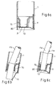
- FIGS. 8 a-c can also be used.
- a container 1 with filler neck 3, which has a cross-sectional taper 2 receives a securing device 400 consisting of two components.
- a steel spring is fastened to the container or filler neck 3 with a holder, for example a screw 405.
- the securing device 400 also consists of a further spring steel as a leg 402, which is also fastened to the filler neck with a holder 405 and has an arc 409 which thus also has a tapering section 6 within the cross-sectional taper 2 of the filler neck forms.
- the spring steel bracket can be bent up elastically by a filling tube FG (not shown) in the region of the bend 409.
- the leg or spring steel bracket 402 preferably has a projection 411 at the end, which serves to support the plate 410. It is pressed out of its position at the same time as the arch 409 through the filling pipe, so that the second arch 407/410 can also clear the way through the tapered section 6.
- the spring steel bracket 410 is pushed away in order to clear the filler neck or the access to the interior of the container for the filling pipe.
- the bottom 410 of the spring steel element can also be designed in the form of a plate, as was shown with other plates with reference to FIGS. 6 a and 7 a.
- the spring steel bracket is replaced by a plastic leg 403 with projection 406, which is mounted on the holder 5 as described above in an elastically resilient and swiveling manner or forms an integrally molded part on the holder.
- 8c shows a variant in which a leg 404 made of plastic has a projection 408 which supports the plate 410.
- a plurality of such brackets can also be used.
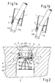
- FIG. 9a shows a sixth embodiment 500 of the device, partly in section, of which the tapered section 6 in Fig. 9b enlarged and pivoted by 90 ° is shown.
- Some parts have the same reference numbers as one or two Apostrophe additives; these indicate different positions of the parts Introduction of a filling pipe FG into the nozzle.
- the filler neck 3 has a funnel-shaped cross-sectional taper 2 that is formed by the bracket 5 with the leg or legs 505.
- Another part or flexible resilient leg 501 is on the Stuck attached, the bow 507 in a plate designed as a lock 510 ends.
- A is placed on or molded onto the plate arcuate element 509, which in a recess 503 on the leg 505 Finds space.
- the leg 505 has a projection 506 Support of the plate 510 on its nose 508 in the rest position according to FIG. 9a.
- the open position of the filler neck when the filler pipe is inserted shows the plate 510 "with element 509".
- FIG. 9b The function of the device is clear in FIG. 9b. If that is dashed FG shown large diameter is inserted, it reaches in Section 6 the element 509 blocking the passage Insert pushes the filling tube FG into position 509 ', it gives way by the resulting force F (arrow) into the recess 503 and takes thereby the plate to position 510 'and at the same time bends the leg 501 in the same direction.
- the integrally formed on the spring steel bracket 11, 401, 501 Bow 407, 507 also as a swivel joint with a return spring be designed.
- FIG. 11 shows a seventh embodiment of the invention.
- the Cross-sectional taper 2 of the filler neck 3 are one or more resilient Bracket 600 with first arches 609 to form the tapered section 6 and integrally formed second arches 610 arranged.
- the bows have the same function as previously described.
- the stirrups 600 are with hooks fixed in holes 605.
- the recesses 607 of the cross-sectional taper 2 provide space for the deformation of the first arches 609 when the Filling tube FG, wherein the arches 609 have a curved spatial shape, see above that the second arches 610 can move sideways and so the passage clear for filling pipes FG.
- an insert 12 a toroid with an outside diameter DG and an inside diameter DK use which is either inserted into the device according to the invention and so then a nozzle with filling pipe FK through the interior of the ring 12 can be inserted, or such an insert 12 is used to on the filling pipe FK to be put on, so that practically a filling pipe FG obtained, which can be used as provided in the invention.
Abstract
Description
Die Erfindung betrifft eine in einen Einfüllstutzen eines Behälters mit großem Durchmesser einsetzbare Vorrichtung als Sperre für das Befüllen des Behälters durch ein Füllrohr kleinen Durchmessers mittels von der Seite her in den Einfüllstutzen ragender, dessen Querschnittsverjüngung auf einen vorbestimmbaren Durchmesser bewirkender, verschiebbarer Sicherungseinrichtung sowie die Verwendung eines rohrförmigen Einsatzes für eine derartige Vorrichtung.The invention relates to a in a filler neck of a container with a large Device that can be used in diameter as a barrier for filling the container through a filling pipe of small diameter from the side into the Filler neck protruding, the cross-sectional tapering to one Predeterminable diameter, displaceable Security device and the use of a tubular insert for such a device.
Aus der DE 196 39 825 A1 ist eine Bleifreisperre zum Einsatz in einen Tankeinfüllstutzen bekannt. Diese Bleifreisperre weist eine Aufnahme für das Rohr einer Flüssigkeitstreibstoffzapfpistole und eine lösbare Querschnittsverjüngung, die in einer Bleifreistellung einen wirksamen Durchmesser hat, der größer ist als das Rohr einer Bleifreizapfpistole und kleiner ist als das Rohr für eine Zapfpistole für Diesel oder verbleiten Kraftstoff, und die in einem gelösten Zustand eine Verbleit/Dieselanordnung bildet und hierbei einen wirksamen Durchmesser freigibt, der größer ist als das Rohr der Zapfpistole für Diesel oder verbleiten Kraftstoff, wobei die Querschnittsverjüngung Teil eines Hebelsystems ist, der zwischen der Bleifreistellung und der Verbleit/Dieselanordnung schwenkbar ist. Dieses Schwenken wird durch Auslösen mittels eines Werkzeuges, insbesondere eines Stiftes durchgeführt und ist dazu bestimmt, daß ein und dieselbe Vorrichtung für Kraftfahrzeuge benutzt werden kann, die bei Montage des Kraftstoffbehälters die Entscheidung verlangt, ob dieser Behälter für ein Fahrzeug mit Betrieb durch bleifreien Kraftstoff, verbleiten Kraftstoff oder Dieselkraftstoff eingesetzt werden soll. Die Verriegelungsstellung wird also einmalig während der Montage des Kraftstoffbehälters mit dem Bleifreieinsatz oder einem anderen Einsatz eingestellt und verbleibt dann so im Kraftfahrzeug.DE 196 39 825 A1 describes a lead free barrier for use in one Tank filler neck known. This lead freeze block has a receptacle for the Pipe a liquid fuel nozzle and a detachable one Cross-sectional rejuvenation that is effective in a lead exemption Has a diameter that is larger than the pipe of a lead nozzle and is smaller than the pipe for a fuel nozzle for diesel or leaded fuel, and which in a released state forms a lead / diesel assembly and this releases an effective diameter that is larger than the pipe Fuel nozzle for diesel or leaded fuel, the Cross-sectional taper is part of a lever system that between the Lead release and the lead / diesel assembly is pivotable. This Swiveling is triggered by a tool, in particular a pen and is designed to be one and the same Device can be used for motor vehicles, which when mounting the The fuel tank's decision requires whether this tank is for a Vehicle powered by unleaded fuel, leaded fuel or Diesel fuel is to be used. The locking position is therefore once during the assembly of the fuel tank with the lead-free insert or another use and then remains in the motor vehicle.
Aus der WO 90/14244 ist ein Einfüllstutzen mit einer Rohrdichtung bekannt, die den Einfüllstutzen bis auf eine Entlüftungsöffnung nach Befüllen mit Kraftstoff luftdicht verschließt. Diese Dichtung ist als trichterförmige Kunststoff- oder Gummimanschette ausgebildet, wobei der Trichter am verjüngten Ende durch eine Ringfeder geschlossen gehalten wird. Eine einzuführende Zapfpistole, gleich welchen Durchmessers, drückt gegen die Wandung des Trichters und öffnet so den Trichterboden, damit Kraftstoff in den Behälter eingefüllt werden kann. Eine Sperre für bestimmte Durchmesser von Füllrohren ist damit nicht verbunden, sondern lediglich ein gasdichter Verschluß des Stutzens nach dem Einfüllen.A filler neck with a pipe seal is known from WO 90/14244 the filler neck except for a vent after filling with fuel hermetically sealed. This seal is as a funnel-shaped plastic or Rubber sleeve formed, with the funnel at the tapered end a ring spring is kept closed. A nozzle to be inserted, whatever the diameter, presses against the wall of the funnel and opens the hopper bottom so that fuel can be filled into the tank can. A lock for certain diameters of filling pipes is therefore not connected, but only a gas-tight closure of the nozzle after the Filling.
Von daher liegt der Erfindung das Problem zugrunde, eine Vorrichtung zur Verwendung im Einfüllstutzen des Behälters, insbesondere eines Kraftfahrzeuges vorzuschlagen, die ein versehentliches Befüllen eines für Dieselkraftstoff vorgesehenen Behälters mit einem anderen Kraftstoff verhindert, wobei unterstellt wird, daß das Füllrohr für Diesel einen größeren Durchmesser hat, als das Füllrohr für andere Kraftstoffarten.The invention is therefore based on the problem of a device for Use in the filler neck of the container, especially one Propose a motor vehicle that accidental filling a for Diesel tank provided with another fuel prevents, assuming that the filling pipe for diesel a larger Diameter than the filler pipe for other types of fuel.
Das Problem wird erfindungsgemäß durch die Merkmale der Ansprüche 1 und
13 gelöst. Weiterbildungen der Erfindung sind in den Unteransprüchen erfaßt.The problem is solved according to the invention by the features of
Es ist bekannt, daß es unmöglich ist, Diesel oder verbleites Benzin in einen Behälter eines Kraftfahrzeuges zu füllen, das für einen Betrieb mit bleifreiem Benzin vorgesehen ist. Weltweit haben handelsübliche Zapfsäulen für Bleifrei-Benzin einen geringeren Durchmesser als Zapfpistolen für verbleites Benzin oder Dieselbenzin. Das Einfüllen von Benzin in einen durch Diesel betriebenes Kraftfahrzeug führt zur Zerstörung der Einspritzpumpe oder des Motors. Andererseits ist zu berücksichtigen, daß im Winter zur Verflüssigung des Diesels manche Fahrer dem Diesel Benzin beimischen.It is known that it is impossible to put diesel or leaded gasoline in one Filling the container of a motor vehicle that is suitable for operation with lead-free Gasoline is provided. There are commercial petrol pumps worldwide for unleaded petrol a smaller diameter than nozzles for leaded petrol or diesel fuel. Filling petrol into a diesel powered one Motor vehicle leads to the destruction of the injection pump or the engine. On the other hand, it should be borne in mind that in winter the liquefaction of the Some drivers add diesel to petrol.
Die Lösung besteht darin, daß bei einer ersten Variante eine in einen Einfüllstutzen mit großem Durchmesser eines Behälters einsetzbare Vorrichtung vorgeschlagen wird, die als Sperre für das Befüllen des Behälters durch ein Füllrohr kleinen Durchmessers dient und die eine von der Seite her in den Einfüllstutzen ragende, dessen Querschnittsverjüngung auf einen vorbestimmbaren Durchmesser bewirkende, verschiebbare Sicherungseinrichtung aufweist, dadurch gekennzeichnet, daß die Sicherungseinrichtung aus mehreren an der Innenwand des Einfüllstutzens mittels einer flexiblen Halterung befestigten, nicht verriegelbaren Teilen besteht, die gemeinsam einen sich verjüngenden Abschnitt im Einfüllstutzen bilden, dessen Abmessung zur Füllöffnung hin dem Füllrohr mit großen Durchmesser und zum Inneren des Behälters dem Füllrohr mit kleinem Durchmesser entspricht und der Abschnitt in einer querliegenden Sperre für die Einschubtiefe des Füllrohres mit kleinem Durchmesser endet, wobei die Teile an der flexiblen Halterung schwenkbar befestigt sind.The solution is that in a first variant one into one Filler neck with large diameter of a container can be used Device is proposed as a lock for filling the container through a filling tube of small diameter and the one from the side in protruding the filler neck, the cross-sectional tapering to one Predeterminable diameter, displaceable Security device, characterized in that the Safety device consisting of several on the inner wall of the filler neck parts that cannot be locked by means of a flexible holder, which together form a tapered section in the filler neck, its dimension towards the filling opening towards the filling pipe with a large diameter and to the inside of the container, the small diameter fill pipe corresponds and the section in a transverse lock for the insertion depth of the filling tube with a small diameter ends, the parts on the flexible Bracket are pivotally attached.
Damit wird es ermöglicht, daß ein Füllrohr großen Durchmessers, wie eine Dieselzapfpistole in den sich verjüngenden Abschnitt eingeschoben wird und Teile der Sicherungseinrichtung an der flexiblen Halterung schwenkend geöffnet werden, so daß der sich verjüngende Abschnitt letztlich an die Zapfpistole anlegen kann. Mit dem Verschwenken der Teile verschwenkt zugleich die querliegende Sperre, so daß das Füllrohr mit großem Durchmesser ungehindert vollständig eingeschoben werden kann.This enables a filling pipe of large diameter, such as a Diesel nozzle is inserted into the tapered section and Swiveling parts of the safety device on the flexible holder be opened so that the tapered section ultimately to the Can nozzle. Swiveled with the swiveling of the parts at the same time the transverse lock, so that the filling pipe with a large diameter can be fully inserted without hindrance.
Sobald ein Füllrohr kleinen Durchmessers, z.B. eine Zapfpistole für bleifreies Benzin eingeschoben wird, werden dagegen die den verjüngenden Abschnitt bildenden Teile nicht schwenkend nach außen verschoben und die querliegende Sperre verhindert, daß das Füllrohr kleinen Durchmessers weiter eingeschoben wird.As soon as a small diameter filling pipe, e.g. a nozzle for lead-free When gasoline is inserted, however, the tapered section forming parts are not pivoted outwards and the Transversal lock prevents the small diameter fill tube from continuing is inserted.
Die Halterung ist ringförmig ausgebildet und an ihr sind zwei oder mehr Teile angeordnet, die Schenkel haben, welche sich fliegend zum Inneren des Behälters erstrecken und an ihrem Ende Vorsprünge aufweisen, die sich zur Mittelachse des Einfüllstutzens erstrecken. Diese Ausformung des verjüngten Abschnittes in Kombination mit der Halterung und der querliegenden Sperre in Form von Vorsprüngen ist eine von mehreren Ausführungsformen einer solchen erfindungsgemäßen Vorrichtung. The bracket is annular and there are two or more parts arranged, the legs, which are flying to the inside of the Extend container and have at their end projections, which to Extend the center axis of the filler neck. This shape of the tapered Section in combination with the bracket and the transverse lock in Projection shape is one of several embodiments such device according to the invention.
Vorzugsweise sind die Teile der Sicherungseinrichtung elastisch und bilden im entlasteten Zustand den sich verjüngenden Abschnitt. Andererseits ist es jedoch auch konstruktiv möglich die Teile nicht elastisch oder im wesentlichen unelastisch auszubilden und durch ein federndes Element miteinander zu koppeln, so daß unter Vorspannung diese Teile den sich verjüngenden Abschnitt bilden, der von einem Füllrohr großen Durchmessers gegen die entsprechende Federspannung geöffnet werden kann. In einer Ausführungsvariante kann das federnde Element als Schraubenfeder oder als elastischer Ring aus Gummi oder Metall ausgebildet, z.B. kann der Ring auch nach Art einer Schraubenfeder aus Metall oder aus elastischem Kunststoff bestehen oder es wird beispielsweise ein Federstahl oder entsprechender Draht verwendet.The parts of the securing device are preferably elastic and form in relieved the tapered section. On the other hand, it is however, the parts are also structurally not elastic or essentially trained inelastic and with each other by a resilient element couple so that these parts under tension the tapered Form the section of a filling pipe against the large diameter appropriate spring tension can be opened. In a Design variant, the resilient element as a coil spring or as elastic ring made of rubber or metal, e.g. the ring can too in the manner of a coil spring made of metal or elastic plastic exist or it will, for example, a spring steel or equivalent Wire used.
In einer Alternative sind die Halterung selbst und die Teile einstückig ausgebildet und als solches in den Stutzen eingesetzt, wobei vorzugsweise als Materialien Kunststoffe oder federnde Metalle verwendet werden. Der verjüngende Abschnitt besteht dabei praktisch aus federnden Verlängerungen der Halterung, die von dem Füllrohr größeren Durchmessers aufgebogen werden, während ein Füllrohr kleinen Durchmessers diese Teile nicht aufbiegen kann, da diese Halterung an ihrem verjüngten Ende dem Durchmesser des kleinen Füllrohres entspricht und damit nicht weiter eingeschoben kann als die querliegende Sperre oder entsprechende Vorsprünge an den Schenkeln zulassen.In an alternative, the bracket itself and the parts are in one piece trained and used as such in the nozzle, preferably as Materials plastics or resilient metals are used. The tapered section practically consists of resilient extensions the bracket, bent up by the filling pipe of larger diameter while a small diameter fill pipe does not bend these parts can, since this holder at its tapered end the diameter of the small filling tube corresponds and can therefore not be inserted further than that transverse lock or corresponding projections on the legs allow.
In einer Ausführungsform kann die Halterung auch als separates Teil, z.B. als ringförmige Torsionsfeder ausgebildet sein, die zugleich am Umfang des Einfüllstutzens oder an dessen Wandung festgelegt ist.In one embodiment, the holder can also be used as a separate part, e.g. as annular torsion spring to be formed, which at the same time on the circumference of Filler neck or is fixed to the wall.
In Weiterbildung der Erfindung werden die querliegende Sperre bzw. die Vorsprünge mit einer elastischen Platte versehen, die einteilig ist oder aus mehreren Teilen besteht, die im entlasteten Zustand eine im wesentlichen geschlossene Kreisringfläche bilden und aus elastischem Material bestehen. In a further development of the invention, the transverse lock or Protrusions provided with an elastic plate that is in one piece or made of consists of several parts, one in the relieved state essentially Form a closed circular surface and consist of elastic material.
Diese Platte wird vorzugsweise unter der Sperre oder den Vorsprüngen
angebracht, z.B. durch Kleben, Verschweißen oder Verschrauben. Eine
derartige elastische Platte wird von der richtigen Fülleinrichtung, einem Füllrohr
großen Durchmessers zusammen mit den Teilen aufgebogen bzw. weg
geschwenkt, so daß das Füllrohr auch die elastische Platte durchstoßen kann,
wenn auch die Rückstellkraft der elastischen Platte überwunden werden muß.
Im Falle des Versuches, ein kleines Füllrohr einzuschieben wird dieses Füllrohr
von der Sperre bzw. den Vorsprüngen gestoppt und bei dem Versuch die
Zapfpistole auszulösen, erzeugt die elastische Platte einen Rückstau, infolge
dessen die handelsüblichen Zapfpistolen mit ihrer Abschaltautomatik den
Durchfluß für große Massenströme sperren.
Für Winterbetrieb, bei dem ein geringer Zusatz an Benzin zum Diesel
erwünscht ist, kann diese Eigenschaft der Platte in Kombination mit der
Abschaltautomatik genutzt werden, um geringe Mengen Bleifrei-Benzin
einzufüllen, trotz der Sperreinrichtung.This plate is preferably attached under the lock or the projections, for example by gluing, welding or screwing. Such an elastic plate is bent or swung away by the correct filling device, a large diameter filling pipe together with the parts, so that the filling pipe can also penetrate the elastic plate, even if the restoring force of the elastic plate has to be overcome. In the event of an attempt to insert a small filler pipe, this filler pipe is stopped by the lock or the projections, and when attempting to trigger the fuel nozzle, the elastic plate creates a back pressure, as a result of which the commercial fuel nozzles with their automatic switch-off block the flow for large mass flows.
For winter operation, where a small addition of petrol to the diesel is desired, this property of the plate can be used in combination with the automatic switch-off to fill in small amounts of unleaded petrol, despite the locking device.
In Variation der generellen Lösung wird erfindungsgemäß vorgeschlagen, daß bei der gattungsgemäßen Vorrichtung die Sicherungseinrichtung als in den Einfüllstutzen ragender Federstahlschenkel ausgebildet ist, der an der oder außerhalb der Wandung des Einfüllstutzens befestigt ist, mit einem ersten Bogen den Querschnitt im Einfüllstutzen auf den kleinen Durchmesser verjüngt mit einem zweiten Bogen an demselben oder einem anderen Schenkel als querliegende Sperre für die Einschubtiefe des Füllrohrs ausgebildet ist, wobei die Sperre zusätzlich mit einer kreisringförmigen Platte versehen sein kann.In a variation of the general solution, the invention proposes that in the generic device, the safety device as in the Filler neck protruding spring steel leg is formed on the or is attached outside the wall of the filler neck, with a first Elbow tapered the cross section in the filler neck to the small diameter with a second bow on the same or a different leg as transverse lock is formed for the insertion depth of the filling tube, wherein the lock can also be provided with an annular plate.
Hier kann der Federstahl den Einfüllstutzen in seinem Querschnitt soweit verringern, daß neben dem ersten Bogen des Federstahles nur ein Füllrohr kleinen Durchmessers vorbei geschoben werden kann, welches dann aber auf die querliegende Sperre tritt und / oder das Einfüllen von nicht erwünschtem Kraftstoff oder ungewollter Kraftstoffmenge mit Hilfe des zweiten Bogens und/ oder der kreisringförmigen Platte verhindert. Sobald ein Füllrohr großen Durchmessers eingeführt wird, wird der erste Bogen des Federstahls durch das größere Füllrohr elastisch gebogen oder verschoben, wodurch sich zugleich die querliegende Sperre, die durch den zweiten Bogen des Federstahlschenkels gebildet wird, öffnet.Here the spring steel can fill the filler neck in its cross section reduce that in addition to the first bend of the spring steel only one fill tube small diameter can be pushed past, but which then the transverse barrier occurs and / or the filling of unwanted Fuel or unwanted amount of fuel using the second sheet and / or the annular plate prevented. Once a fill pipe big Diameter is introduced, the first arch of the spring steel is through the larger filler tube bent or shifted elastically, which at the same time the transversal lock through the second arch of the spring steel leg is formed, opens.
Ergänzend wird vorgeschlagen einen rohrförmigen Einsatz zu verwenden für
den Fall, daß in den Dieselbehälter im Winterbetrieb doch beispielsweise
Benzin oder andere Zusätze zugefügt werden sollen. Der Einsatz ist in eine der
zuvor beschriebenen Vorrichtungen einsetzbar und entsprechend verwendbar,
wenn er eine Wandung hat, deren Dicke der Dicken-Differenz zwischen dem
großen und kleinen Durchmesser der beschriebenen Füllrohre aufweist, um
dann durch den Innendurchmesser des Einsatzes hindurch das Befüllen des
Dieselbehälters mit einer Benzinzapfpistole zu gestatten.
Letztlich kann der Einsatz auch so gestaltet sein, daß er zuvor auf die
Benzinzapfpistole aufgesetzt oder dort angeordnet wird und somit dann ein
Füllrohr großen Durchmessers simuliert.In addition, it is proposed to use a tubular insert in the event that, for example, gasoline or other additives are to be added to the diesel container during winter operation. The insert can be used in one of the devices described above and can be used accordingly if it has a wall whose thickness has the difference in thickness between the large and small diameters of the filling tubes described, and then also fills the diesel container through the inside diameter of the insert to allow a gasoline nozzle.
Ultimately, the insert can also be designed in such a way that it is previously placed on the gasoline nozzle or arranged there and thus simulates a filling pipe of large diameter.
Additiv oder alternativ kann die Sperreinrichtung mit dem Füllrohr kleinen Durchmessers auch durch eine z.B. mechanische Einrichtung vorgebbare Rechts-Links-Bewegung bzw. schraubenförmige Bewegung entriegelt werden.Additively or alternatively, the locking device with the filling tube can be small Diameter also by e.g. predeterminable mechanical device Right-left movement or helical movement can be unlocked.
Anhand einer schematischen Zeichnung soll die Erfindung näher erläutert werden; dabei werden auch andere Zwecke und die Vorteile der Erfindung offenbar. Es zeigen:
- Fig. 1 a, b
- Einfüllstutzen nach dem Stand der Technik in Gebrauchssituation bei Benutzung eines kleinen Füllrohres und eines großen Füllrohres;
- Fig. 2
- eine erste Ausführungsform der erfindungsgemäßen Vorrichtung;
- Fig. 3a, b
- eine zweite Ausführungsform der Vorrichtung gemäß der Erfindung;
- Fig. 4 a, b
- eine dritte Ausführungsform der erfindungsgemäßen Vorrichtung;
- Fig. 5 a, b,
- c eine vierte Ausführungsform der erfindungsgemäßen Vorrichtung;
- Fig. 6 a, b,
- ceine Ausführungsform gemäß den Figuren 5 a, b, c mit einer Rückstauplatte;
- Fig. 7 a - d
- eine vierte Ausführungsform gemäß Fig. 5 a, b, c mit einer zweiten Form der Rückstauplatte;
- Fig. 8 a - c
- eine fünfte Ausführungsform in Varianten mit unterstützter Platte;
- Fig. 9.a, b
- eine sechste Ausführungsform, teils vergrößert dargestellt und
- Fig. 10
- eine siebte Ausführungsform der Erfindung;
- Fig. 11
- eine erfindungsgemäßer Einsatz zur Verwendung mit der erfindungsgemäßen Vorrichtung.
- Fig. 1 a, b
- Filler neck according to the state of the art in the use situation when using a small filling pipe and a large filling pipe;
- Fig. 2
- a first embodiment of the device according to the invention;
- 3a, b
- a second embodiment of the device according to the invention;
- 4 a, b
- a third embodiment of the device according to the invention;
- 5 a, b,
- c a fourth embodiment of the device according to the invention;
- 6 a, b,
- c an embodiment according to FIGS. 5 a, b, c with a backflow plate;
- Fig. 7 a - d
- a fourth embodiment of Figure 5 a, b, c with a second shape of the backflow plate.
- 8 a - c
- a fifth embodiment in variants with a supported plate;
- Fig. 9.a, b
- a sixth embodiment, shown partially enlarged and
- Fig. 10
- a seventh embodiment of the invention;
- Fig. 11
- an insert according to the invention for use with the device according to the invention.
In den folgenden Figuren werden identische Bezugszeichen für identische oder äquivalent wirkende Bauteile benutzt.In the following figures, identical reference numerals for identical or equivalent components used.
Figuren 1 a und 1b zeigen für einen Behälter 1, z.B. einen Kraftstofftank eines
Fahrzeuges, einen Einfüllstutzen 3 mit einer Querschnittsverjüngung 2, welche
eine Öffnung aufweist, durch die ein Füllrohr FG mit großem Durchmesser DG
bzw. ein Füllrohr FK kleinen Durchmessers DK hindurch reicht, um den
Behälter 1 zu füllen. Das Füllrohr FG gehört beispielsweise zu einer Zapfpistole
für Dieseltreibstoff und das Füllrohr FK zu einer Zapfpistole für bleifreien
Kraftstoff. Der Durchmesser DG entspricht für den Behälter 1 mit der Öffnung
an der Querschnittsverjüngung 2, dem bestimmungsgemäß zu verwenden
Füllrohr FG für Dieselkraftstoff. Figur 1b zeigt, daß nach dem Stand der
Technik der Behälter 1 auch mit einem Füllrohr FK befüllt werden kann, wobei
ein Befüllen dieses Behälters 1 mit bleifreiem Kraftstoff, z.B. mit der Zapfpistole
mit Füllrohr FK zu erheblichen Schäden führen kann.Figures 1a and 1b show for a
Figur 2 zeigt daher eine erste Variante der ersten Lösung der Erfindung, bei der
für den Behälter 1 mit dem Einfüllstutzen 3 in einer Querschnittsverjüngung 2
eine Sicherungseinrichtung 4 eingesetzt ist, die ein Füllen des Behälters 1 mit
einer Fülleinrichtung FK ausschließen soll. Die Sicherungseinrichtung 4 verfügt
über eine Halterung 5, mit der sie - in nicht dargestellter Weise - an der
Innenwandung des Einfüllstutzens 3 befestigt ist. Die Sicherungseinrichtung 4
enthält mindestens zwei, vorzugsweise drei oder mehr, Schenkel 7, die L-förmig
ausgebildet sind und gemeinsam einen verjüngenden Abschnitt 6 im
Einfüllstutzen 3 umschließen. Dieser verjüngende Abschnitt hat zur Füllseite,
d.h. nach außen, zunächst einen Durchmesser DG entsprechend dem
bestimmungsgemäß einzuführenden Füllrohr FG und verjüngt sich in Richtung
des Behälterinneren auf einen Durchmesser DK entsprechend dem Füllrohr FK
mit dem kleinen Durchmesser DK. Die Schenkel haben zur Seite des
Behälterinneren, wo sie etwa einen Durchmesser DK bilden, eine
Sperreinrichtung, hier als Schenkelverlängerung 8 der Schenkel 7 dargestellt,
die sich in Richtung auf die Mitte des Einfüllstutzens erstreckt. In der gezeigten
Lage werden die Schenkel 7 gehalten durch eine Schraubenfeder 42, deren
Lage durch einen Drahtkäfig 43 und einen Bund 41 an den Schenkeln 7
bestimmt wird. Sobald eine Zapfpistole mit Füllrohr FG mit entsprechendem
Durchmesser DG eingeführt wird, schwenken die Schenkel 7 um die Halterung
5 bei Überwindung der Federkraft der Schraubenfeder 42 so in den
Schwenkraum 9, daß ein Durchlaß entsprechend dem Durchmesser DG in dem
Einfüllstutzen 3 frei wird und analog Figur 1 a das Füllrohr FG in den
Einfüllstutzen 3 zum Befüllen des Behälters 1 eingeführt werden kann.FIG. 2 therefore shows a first variant of the first solution of the invention, in which
for the
Wird nun versucht, mit einer Zapfpistole mit Füllrohr FK in den Einfüllstutzen 3
einzudringen, so stößt das Füllrohr FK mit dem Durchmesser DK auf die
Schenkelfortsetzungen 8, die hier eine Sperre bilden, und das Füllrohr FK kann
nicht weit in den Einfüllstutzen 3 eingebracht werden. Zumindest ist der
Federdruck so groß, daß nur mit erheblichem Widerstand die
Sicherungseinrichtung geöffnet werden könnte.Now try, with a nozzle with filling pipe FK in the
Wichtig ist, daß mit dem Füllrohr FG, beginnend am Durchmesser DG der
Sicherungseinrichtung, schon die Schwenkbewegung der Schenkel 7 um die
Halterung 5 eingeleitet wird, während dies bei dem Füllrohr FK unmöglich ist.It is important that with the filling pipe FG, starting at the diameter DG the
Securing device, already the pivoting movement of the
Figur 3 a zeigt eine Vorrichtung mit derselben Wirkung, wie bei Figur 2. Der
Behälter 1 weist einen Einfüllstutzen 3 und eine Querschnittsverjüngung 2 auf.
Am Einfüllstutzen 3 ist eine Sicherungseinrichtung 40 angebracht, welche aus
einem elastischen Haltering 5 und Schenkeln 7 besteht, die an dem elastischen
Haltering schwenkbar angekoppelt sind. Die Befestigung des Halteringes 7 an
dem Einfüllstutzen bzw. in der Querschnittsverjüngung 2 ist nicht dargestellt. Figure 3a shows a device with the same effect as in Figure 2.
Auch hier haben die Schenkel 7 eine als Sperre wirkende L-förmige
Verlängerung 8, die ein Durchgreifen eines Füllrohres FK mit kleinem
Durchmesser DK nicht zulassen. Die Schenkel 7 bilden wiederum im
Einfüllstutzen bzw. dessen Querschnittsverjüngung einen verjüngenden
Abschnitt 6, wie dies aus Figur 3 a deutlich wird.Here, too, the
Figur 3 b zeigt nun die Interaktion einer Sicherungseinrichtung 40 mit einem
Füllrohr FG mit großem Durchmesser DG. Sobald das Füllrohr FG den Bereich
des Halteringes 5 erreicht, kippen die Schenkel 7 mit den
Schenkelverlängerungen 8 nach außen, maximal bis die Führungsteile 71 der
Schenkel 7 nach Schwenken um den Haltering 5 am Füllrohr FG anliegen.
Während des Einführens des Füllrohres FG spreizt sich der Haltering 5, z.B.
bestehend aus einer Drahtfeder, und die Schenkel 7, in diesem Fall auch der
als Feder ausgebildete Haltering 5, werden in den Schwenkraum 9 des
Behälters 1 verdrängt, so daß das Füllrohr FG Einlaß zu dem Behälter findet.Figure 3 b shows the interaction of a
Figuren 4 a, 4 b zeigen einen zum Stand der Technik gemäß Figuren 1 a, b im
wesentlichen identischen Aufbau, jedoch ist der Bereich der
Querschnittsverjüngung 2 im Einfüllstutzen 3 mit einer Sicherungseinrichtung
versehen, welche hier aus den Schenkeln 70 und der Sperre 80 für Füllrohre
FK besteht. Die Schenkel 70 bzw. die Sperre 80, sind hier aus dem selben
Material gefertigt, wie der Einfüllstutzen bzw. das Behälterteil 1 selbst, z.B.
einem Kunststoffteil, jedoch bilden die Schenkel 70 mit der Sperre 80 ein
integrales Teil mit dem Einfüllstutzen bzw. dessen Querschnittsverjüngung 2.
Der verjüngende Abschnitt ist im Schnitt gemäß Figur 4 a, welche eine
Schnittlage IV - IV in Figur 4 b darstellt, deutlich zu erkennen. In der Draufsicht
auf die Situation am Einfüllstutzen gemäß Figur 4 b, dessen Mittelachse A
eingezeichnet ist, läßt sich deutlich erkennen, daß die Schenkel 70 in Richtung
auf die Mittelachse A des Einfüllstutzens vorspringen und in den Sperren 80
enden.Figures 4 a, 4 b show one of the prior art according to Figures 1 a, b in
essentially identical structure, however, the area of
Die Figuren 5 a, b, c zeigen eine den Figuren 4 a, 4 b, ähnliche Situation,
jedoch sind hier vier Schenkel 70 mit vier Sperren 80 dargestellt, im Gegensatz
zu den drei Schenkeln 70 mit entsprechender Zahl von Sperren 80 gemäß den
Figuren 4 a, 4 b. In der Figur 5 b ist zu erkennen, wie ein Füllrohr FG mit
Durchmesser DG in die Vorrichtung gemäß der Erfindung mit der
Sicherungseinrichtung problemlos eingeführt werden kann. Dabei werden die
Schenkel 70 im Einfüllstutzen, genauer im Bereich der Querschnittsverjüngung
bzw. dem verjüngenden Abschnitt 6 so gespreizt, daß auch die Sperren 80
zugleich mit den Schenkeln 70 weg schwenken und das Füllrohr FG
durchlassen. In diesem Falle kann die Zapfpistole mit Füllrohr FG mit Hilfe von
Füllrohrrasten FR, wie vom Autofahrer gewohnt, am Rande des Einfüllstutzens
bzw. Behälters 1 eingerastet werden und die Automatikfunktion der Zapfpistole
eingestellt werden. Damit ist dann ohne Eingriff des Benutzers ein weiteres
Füllen des Behälters, welches in der Regel minutenlang dauert, möglich. Für
den Fall, daß eine solche Einrastung nicht geschieht, wird der Autofahrer
zusätzlich aufmerksam, daß irgend etwas beim Tankvorgang nicht dem
normalen Ablauf entspricht. Eine solche Situation wird der Benutzer vorfinden,
wenn gemäß Figur 5 c ein kleines Füllrohr FK mit dem Durchmesser DK in
einen Behälter 1 mit der erfindungsgemäßen Vorrichtung, hier dargestellt durch
die Schenkel 70 des verjüngenden Abschnittes, sowie die Sperren 80,
vorfindet. In diesem Fall können die Füllrohrrasten FR nicht am Rand des
Behälters einrasten und der Benutzer wird aufmerksam, daß hier eine Situation
gegeben ist, die es ihm unmöglich macht, das Füllrohr FK weiter in den
Behälter 1 einzuschieben, weil es an den Sperren 80 blockiert wird.FIGS. 5 a, b, c show a situation similar to FIGS. 4 a, 4 b,
however, four
Gemäß einer Weiterbildung der Erfindung kann eine Ausführungsform der
Erfindung gemäß der Figuren 5 a - c zusätzlich noch mit einer, die Einfüllung
von Kraftstoff behindernden Platte 10 versehen werden, was in den Figuren 6
a, b, c dargestellt ist. Ein solche Platte, z.B. aus einem federnden Metall, ist
schematisch als Platte 10 dargestellt, die mittels einer Plattenhalterung 11 in
nichtdargestellter Weise am Behälter 1 bzw. im Einfüllstutzen befestigt und
verschließt unterhalb der Schenkel 70 bzw. der Sperren 80 die Öffnung 21 zum
Behälter. Diese Platte 10 aus Federstahl oder einem stabilen, federnden
Kunststoff kann gemäß Figur 6 b durch ein Füllrohr FG bestimmungsgemäß
aufgedrückt werden, nachdem die Schenkel 70, wie zuvor bereits in Figur 5 b
dargestellt, auf geschwenkt bzw. aufgebogen wurden. Figur 6 c zeigt wiederum,
daß mit einem Füllrohr FK dies nicht möglich ist, da die Schenkel 70 sich nicht
aufbiegen und das Füllrohr FK in der Einschubtiefe durch die Sperre 80
begrenzt wird und so gar nicht die Platte 10 erreicht. Die Platte 10 hat die
Zusatzfunktion im Falle, daß die Zapfpistole mit Füllrohr FK in Funktion gesetzt
wird, der Kraftstoff auf die Platte 10 prallt und durch den Rückstau die
Automatikfunktion der Zapfpistole außer Betrieb setzt und kein weiterer
Kraftstoff in Behälter 1 eingefüllt werden kann.According to a development of the invention, an embodiment of the
Invention according to Figures 5 a - c additionally with one, the filling
of fuel-obstructing
Eine Alternative zu der Platte 10 ist dargestellt in den Figuren 7 a, 7 b, 7 c, 7 d.
Figur 7 a zeigt wiederum eine Situation gemäß Figur 5 a, wobei jedoch zum
Behälterinneren unterhalb der Sperren 80 eine einstückige Platte aus
Kunststoff oder Gummi, Bezugszeichen 100, angeordnet wird. Pfeil VII weist zu
einer Ansicht gemäß Figur 7 d mit einer alternativen Ausführungsform der
Platte 100. Hier besteht die Platte aus vier Segmenten 110, die jeweils unter
die Sperren 80 der Schenkel 70 angeklebt sind und im wesentlichen, bis auf
einen kleinen Durchlaß in der Mitte, welche zugleich eine Entlüftung des
Behälters ermöglicht, einen Verschluß des Einfüllstutzens. In einer derartigen
Bauform ist auch hier eine erfindungsgemäße Sperre in einer Art und Weise
möglich, wie dies bereits zu den Figuren 5 und 6 beschrieben wurde. Figur 7 b
zeigt, wie Segmente 110 sich elastisch öffnen, wenn Füllrohr FG mit dem
richtigen Durchmesser benutzt wird, um den Behälter 1 zu füllen. Wie bereits
zur Figur 6 c dargestellt, wird auch gemäß Figur 7 c ein kleines Füllrohr FK
durch die Schenkel 70 bzw. Sperren 80 behindert, weiter in den Behälter
einzudringen. Die Platte 100 verhindert in zuvor bereits geschilderter Weise,
daß in dieser Position Kraftstoff in den Behälter eingefüllt wird.An alternative to the
Gemäß einer anderen Lösung der Erfindung können auch Ausführungsformen
gemäß Fig. 8 a -c Verwendung finden. Ein Behälter 1 mit Einfüllstutzen 3, der
eine Querschnittsverjüngung 2 aufweist, erhält eine Sicherungseinrichtung 400
aus zwei Komponenten. Eine Stahlfeder ist mit einer Halterung z.B. einer
Schraube 405 am Behälter bzw. Einfüllstutzen 3 befestigt ist.
In einem Fall (Fig. 8a) besteht die Sicherungseinrichtung 400 noch aus einem
weiteren Federstahl als Schenkel 402, der ebenfalls mit einer Halterung 405 am
Einfüllstutzen befestigt ist und einen Bogen 409 hat, welcher so innerhalb der
Querschnittsverjüngung 2 des Einfüllstutzens noch einen verjüngenden
Abschnitt 6 bildet. Der Federstahlbügel kann von einem - nicht dargestellten -
Füllrohr FG im Bereich des Bogens 409 elastisch aufgebogen werden. Der
Schenkel oder Federstahlbügel 402 weist am Ende vorzugsweise einen
Vorsprung 411 auf, der der Unterstüzung der Platte 410 dient. Er wird zugleich
mit dem Bogen 409 durch das Füllrohr aus seiner Lage gedrückt, so daß auch
der zweite Bogen 407 / 410 den Weg durch den verjüngten Abschnitt 6 frei
machen kann. Beim Einführen eines bestimmungsgemäßen Füllrohres FG wird
der Federstahlbügel 410 weggedrückt, um so den Einfüllstutzen bzw. den
Zugäng zum Behälterinneren für das Füllrohr frei zu machen.
Der Boden 410 des Federstahlelementes kann auch plattenförmig ausgebildet
sein, wie dies anhand der Figuren 6 a und 7 a mit anderen Platten dargestellt
wurde.
In einer Variante gemäß Fig. 8b ist der Federstahlbügel durch einen Kunststoff-Schenkel
403 mit Vorsprung 406 ersetzt, der an der Halterung 5 wie zuvor
beschrieben elastisch federnd und fliegend schwenkbar gelagert ist bzw ein an
der Halterung integral angespritztes Teil bildet.
In ähnlicher Weise zeigt Fig. 8c eine Variante, bei der ein Schenkel 404 aus
Kunststoff einen Vorsprung 408 hat, der die Platte 410 unterstützt.
Anstelle eines einzelnen dargestellten Federstahlbügels 402 bzw. der
elastischen Schenkel 403 und 404 kann auch eine Mehrzahl derartiger Bügel
benutzt werden.According to another solution of the invention, embodiments according to FIGS. 8 a-c can also be used. A
In one case (FIG. 8a), the securing
The
In a variant according to FIG. 8b, the spring steel bracket is replaced by a
8c shows a variant in which a
Instead of a single
Fig. 9a zeigt teils im Schnitt eine sechste Ausführungsform 500 der Vorrichtung,
von der der verjüngte Abschnitt 6 in Fig. 9b vergrößert und um 90° geschwenkt
dargestellt ist. Die Bezugszeichen einiger Teile haben teils ein oder zwei
Hochkommazusätze; diese bezeichnen verschiedene Stellungen der Teile bei
Einführung eines Füllrohres FG in den Stutzen.9a shows a
Der Einfüllstutzen 3 hat eine trichterförmige Querschnittsverjüngung 2, die
durch die Halterung 5 mit dem oder den Schenkeln 505 gebildet wird. Ein
weiteres Teil oder flexibler federnd beweglicher Schenkel 501 ist an dem
Stutzen befestigt, dessen Bogen 507 in einer als Sperre ausgebildeten Platte
510 endet. Auf die Platte aufgesetzt oder daran angeformt ist ein
bogenförmiges Element 509, das in einer Ausnehmung 503 am Schenkel 505
Platz findet. Der Schenkel 505 weist einen Vorsprung 506 auf zur
Unterstützung der Platte 510 an dessen Nase 508 in Ruheposition gemäß Fig.
9a. Die Offenposition des Einfüllstutzens bei eingestecktem Füllrohr zeigt Platte
510" mit Element 509".The
In Fig. 9b wird die Funktion der Vorrichtung deutlich. Wenn das gestrichelt
dargestellte Füllrohr FG großen Durchmessers eingeführt wird, erreicht es im
Abschnitt 6 das das den Durchgang sperrende Element 509. Bei weiterem
Einführen drückt das Füllrohr FG das Element in die Position 509', es weicht
durch die resultierende Kraft F (Pfeil) in die Ausnehmung 503 aus und nimmt
dabei die Platte zur Position 510' mit und verbiegt zugleich den Schenkel 501 in
dieselbe Richtung. Dabei wird die Platte 510' bzw. deren Nase 508 von der
Unterstützung 506 gezogen. Bei weiterem Durchstecken des Füllrohres FG wird
die Platte aufgestoßen und gelangt in die Endpostion 510"; hier hat der
Schenkel 501" seine größte Auslenkung und maximale Rückstellkraft, Wenn
das Füllrohr FG zurückgezogen wird, schwenkt die Platte 510" in ihre
Schließposition 510 zurück und sperrt den Durchgang für kleine Füllrohre FK.The function of the device is clear in FIG. 9b. If that is dashed
FG shown large diameter is inserted, it reaches in
Im übrigen kann der integral am Federstahlbügel 11, 401, 501 angeformte
Bogen 407, 507 auch als Drehgelenk mit einer rückstellenden Feder
ausgestaltet sein.Otherwise, the integrally formed on the
Fig. 11 zeigt eine siebte Ausführungsform der Erfindung. In der
Querschnittsverjüngung 2 des Einfüllstutzens 3 sind ein oder mehrere federnde
Bügel 600 mit ersten Bögen 609 zur Bildung des verjüngten Abschnitts 6 und
integral angeformten zweiten Bögen 610 angeordnet. Die Bögen haben
dieselbe Funktion wie bereits zuvor beschrieben. Die Bügel 600 sind mit Haken
in Bohrungen 605 fixiert. Die Ausnehmungen 607 der Querschnittsverjüngung 2
bieten Platz für die Verformung der ersten Bögen 609 bei Einführen des
Füllrohres FG, wobei die Bögen 609 eine geschwungene Raumform haben, so
daß die zweiten Bögen 610 seitlich ausweichen können und so den Durchgang
freimachen für Füllrohre FG.11 shows a seventh embodiment of the invention. In the
In manchen Fällen, insbesondere im Winterbetrieb möchten Kraftfahrer
Dieselkraftstoff bessere Fließeigenschaften geben, indem sie dem Diesel im
Behälter 1 zusätzlich und bewußt Benzin zugeben. In diesem Falle könnte bei
einem, mit der Erfindung ausgerüsteten, Einfüllstutzen kein Befüllen des
Behälters 1 erfolgen, weil wie dargestellt, ein Füllrohr kleineren Durchmessers
mit dem Benzin eingefüllt wird, nicht in den Einfüllstutzen gelangen kann. Für
diesen Zweck wird gemäß Figur 11 vorgeschlagen, einen Einsatz 12, ein Toroid
mit einem Außendurchmesser DG und einem Innendurchmesser DK zu
verwenden, der entweder in die erfindungsgemäße Vorrichtung eingefügt wird
und so dann eine Zapfpistole mit Füllrohr FK durch das Innere des Ringes 12
eingeführt werden kann, oder ein derartiger Einsatz 12 wird verwendet, um auf
das Füllrohr FK aufgesetzt zu werden, um so praktisch ein Füllrohr FG zu
erhalten, das wie bei der Erfindung vorgesehen Verwendung finden kann.In some cases, especially in winter, drivers may want to
Giving diesel fuel better flow properties by giving the diesel in the
Claims (14)
Priority Applications (2)
| Application Number | Priority Date | Filing Date | Title |
|---|---|---|---|
| EP01129821A EP1319545B2 (en) | 2001-12-14 | 2001-12-14 | Arrangement for refueling a diesel vehicle |
| DE50112972T DE50112972D1 (en) | 2001-12-14 | 2001-12-14 | Device for refueling diesel vehicles |
Applications Claiming Priority (1)
| Application Number | Priority Date | Filing Date | Title |
|---|---|---|---|
| EP01129821A EP1319545B2 (en) | 2001-12-14 | 2001-12-14 | Arrangement for refueling a diesel vehicle |
Publications (3)
| Publication Number | Publication Date |
|---|---|
| EP1319545A1 true EP1319545A1 (en) | 2003-06-18 |
| EP1319545B1 EP1319545B1 (en) | 2007-09-05 |
| EP1319545B2 EP1319545B2 (en) | 2010-08-25 |
Family
ID=8179546
Family Applications (1)
| Application Number | Title | Priority Date | Filing Date |
|---|---|---|---|
| EP01129821A Expired - Lifetime EP1319545B2 (en) | 2001-12-14 | 2001-12-14 | Arrangement for refueling a diesel vehicle |
Country Status (2)
| Country | Link |
|---|---|
| EP (1) | EP1319545B2 (en) |
| DE (1) | DE50112972D1 (en) |
Cited By (34)
| Publication number | Priority date | Publication date | Assignee | Title |
|---|---|---|---|---|
| GB2391544A (en) * | 2002-08-01 | 2004-02-11 | Stephen Nicholl | Fuel tank filler neck having a blocking member |
| WO2004101305A1 (en) * | 2003-05-09 | 2004-11-25 | Advance Technology Venture Ltd. | Filler pipe |
| EP1625964A2 (en) * | 2004-08-11 | 2006-02-15 | Stant Manufacturing Inc. | Fuel-dispensing nozzle inhibitor |
| EP1627761A2 (en) * | 2004-08-11 | 2006-02-22 | Stant Manufacturing Inc. | Fuel-dispensing nozzle inhibitor |
| US7011121B2 (en) | 2004-04-08 | 2006-03-14 | I.T.W. De France | End piece for a fuel filler pipe of a vehicle |
| EP1642761A1 (en) * | 2004-09-30 | 2006-04-05 | Stant Manufacturing Inc. | Fuel-dispensing nozzle inhibitor |
| WO2006066294A1 (en) * | 2004-12-20 | 2006-06-29 | Tesma Motoren- Und Getriebetechnik Gmbh | Cap-free filler pipe for the tank of a motor vehicle |
| EP1690726A1 (en) * | 2005-02-10 | 2006-08-16 | Gerdes GmbH | Capless filler nozzle end-piece for a vehicle fuel tank |
| DE102005047459A1 (en) * | 2005-09-30 | 2006-08-24 | Alfmeier Präzision AG Baugruppen und Systemlösungen | Tank filling neck for diesel vehicle has carrier element held by spring in rest position, and projecting less into filling channel than locking element |
| WO2007013863A2 (en) * | 2005-07-27 | 2007-02-01 | Janez Alic | Diesel fuel tank entry protection accessory |
| WO2007012488A1 (en) * | 2005-07-27 | 2007-02-01 | Reutter Gmbh | Incorrect-refuelling arrangement |
| GB2431634A (en) * | 2005-10-25 | 2007-05-02 | Rhys Holdaway | Device to prevent incorrect fuelling of a vehicle |
| DE102005053793A1 (en) * | 2005-11-09 | 2007-05-10 | Alfmeier Präzision AG Baugruppen und Systemlösungen | Filler neck for diesel automobile, has swiveling part which is arranged in fueling channel whereby fuelling channel is supported at swiveling axis that is outside fueling channel |
| WO2007091079A1 (en) * | 2006-02-09 | 2007-08-16 | Mark Wells | Device for preventing full introduction of a first conduit into a second conduit |
| WO2007104762A1 (en) * | 2006-03-15 | 2007-09-20 | Inergy Automotive Systems Research (Société Anonyme) | Fuel-dispensing nozzle inhibitor |
| FR2898550A1 (en) * | 2006-03-15 | 2007-09-21 | Inergy Automotive Systems Res | Fuel e.g. diesel, tank`s filling pipe securing device for e.g. rental car, has stopping device formed to introduce diesel pump nozzle in filling pipe of tank, while preventing introduction of petrol pump nozzle in filling pipe |
| US7293586B2 (en) | 2005-06-22 | 2007-11-13 | Stant Manufacturing Inc. | Fuel-dispensing nozzle inhibitor |
| WO2008059228A1 (en) * | 2006-11-13 | 2008-05-22 | Diesel International Limited | Improved filler neck |
| WO2008127916A1 (en) * | 2007-04-16 | 2008-10-23 | Illinois Tool Works Inc. | Selective fuel nozzle inhibiting system |
| WO2009007385A1 (en) * | 2007-07-11 | 2009-01-15 | Inergy Automotive Systems Research (Societe Anonyme) | System for filling a tank |
| WO2009022140A2 (en) * | 2007-08-15 | 2009-02-19 | Diesel Do Nicely Limited | Device for connection to a fluid inlet of a fuel tank |
| GB2456178A (en) * | 2008-01-05 | 2009-07-08 | Neill Mills | A diesel fuel tank safety insert |
| JP2009234312A (en) * | 2008-03-26 | 2009-10-15 | Fuji Heavy Ind Ltd | Erroneous fuel feeding prevention device |
| WO2009135954A2 (en) | 2008-05-09 | 2009-11-12 | Gerdes Gmbh | Neck end for a filler neck |
| US7665493B2 (en) | 2005-02-10 | 2010-02-23 | Stant Manufacturing Inc. | Fuel-dispensing nozzle inhibitor |
| WO2010023810A1 (en) * | 2008-08-25 | 2010-03-04 | 株式会社ニフコ | Device for preventing fueling error |
| DE102009007866A1 (en) | 2009-02-06 | 2010-08-12 | Daimler Ag | Motor vehicle i.e. passenger car, tank for storing e.g. liquid fuel, has pivotable flap valve assigned to cross sectional reducing unit and loaded with spring force, where flap valve and reducing unit consist of plastic and metal |
| EP1319545B2 (en) † | 2001-12-14 | 2010-08-25 | Ford Global Technologies, LLC | Arrangement for refueling a diesel vehicle |
| DE112009002053T5 (en) | 2008-09-04 | 2011-06-22 | I.T.W. De France | Fuel filler pipe tail for vehicles |
| US7967041B2 (en) | 2007-07-19 | 2011-06-28 | Stant Usa Corp. | Fuel-dispensing nozzle inhibitor |
| WO2012034643A1 (en) * | 2010-09-16 | 2012-03-22 | Kautex Textron Gmbh & Co. Kg | Filler neck for a fuel tank of a motor vehicle |
| EP2562024A1 (en) * | 2011-08-25 | 2013-02-27 | Gerdes GmbH | Cap-free closable filler neck end |
| WO2013050486A1 (en) * | 2011-10-04 | 2013-04-11 | Tecinnovation Gmbh | Safety device for a container |
| US10000117B2 (en) | 2012-02-17 | 2018-06-19 | Stant Usa Corp. | Filler neck closure assembly |
Families Citing this family (2)
| Publication number | Priority date | Publication date | Assignee | Title |
|---|---|---|---|---|
| DE102007063338A1 (en) | 2007-12-20 | 2009-04-16 | Alfmeier Präzision AG Baugruppen und Systemlösungen | Diesel engine vehicle refueling device for use in vehicle tool i.e. spare can, has cone provided in direction and opening breaking through wall of insertion section, where inlet section is arranged at opposite end of insertion section |
| DE102008009252A1 (en) | 2008-02-15 | 2009-08-20 | Konstantinos Tsiberidis | Wrong fuel-filling prevention device for motor vehicle, has nozzle radially arranged between contact surfaces and moving inwardly to center longitudinal axis during rotation of locking elements from locking position into release position |
Citations (5)
| Publication number | Priority date | Publication date | Assignee | Title |
|---|---|---|---|---|
| US3880317A (en) * | 1973-03-02 | 1975-04-29 | Ford Motor Co | Inlet insert |
| DE3641274A1 (en) * | 1985-12-11 | 1987-06-19 | Volkswagen Ag | Filler lock for the filler neck of a tank, especially a fuel tank |
| GB2230765A (en) * | 1989-04-15 | 1990-10-31 | Ford Motor Co | Insert for restricting access to fuel tank |
| WO1990014244A1 (en) | 1989-05-17 | 1990-11-29 | Vernay Laboratories, Inc. | Fuel filler pipe seal |
| DE19639825A1 (en) | 1995-10-06 | 1997-04-10 | Volkswagen Ag | Fuel inlet point for vehicle tank |
Family Cites Families (6)
| Publication number | Priority date | Publication date | Assignee | Title |
|---|---|---|---|---|
| US4034784A (en) † | 1974-08-14 | 1977-07-12 | General Motors Corporation | Filler neck to inhibit use of leaded fuel |
| DE8528368U1 (en) † | 1985-10-04 | 1985-11-28 | Blau KG, 4018 Langenfeld | Reduction insert for a tank filler neck |
| FR2741014B1 (en) † | 1995-11-15 | 1998-01-09 | Peugeot | DECEPTING DEVICE FOR THE FUEL CONDUIT OF A MOTOR VEHICLE |
| US6302169B1 (en) † | 2000-09-13 | 2001-10-16 | Peter C. Pulos | Diesel fuel nozzle restrictor |
| DE10126207A1 (en) † | 2001-05-30 | 2003-01-16 | Bayerische Motoren Werke Ag | Motor vehicle fuel tank with a filler neck for holding a fuel nozzle for diesel fuel |
| EP1319545B2 (en) † | 2001-12-14 | 2010-08-25 | Ford Global Technologies, LLC | Arrangement for refueling a diesel vehicle |
-
2001
- 2001-12-14 EP EP01129821A patent/EP1319545B2/en not_active Expired - Lifetime
- 2001-12-14 DE DE50112972T patent/DE50112972D1/en not_active Expired - Lifetime
Patent Citations (5)
| Publication number | Priority date | Publication date | Assignee | Title |
|---|---|---|---|---|
| US3880317A (en) * | 1973-03-02 | 1975-04-29 | Ford Motor Co | Inlet insert |
| DE3641274A1 (en) * | 1985-12-11 | 1987-06-19 | Volkswagen Ag | Filler lock for the filler neck of a tank, especially a fuel tank |
| GB2230765A (en) * | 1989-04-15 | 1990-10-31 | Ford Motor Co | Insert for restricting access to fuel tank |
| WO1990014244A1 (en) | 1989-05-17 | 1990-11-29 | Vernay Laboratories, Inc. | Fuel filler pipe seal |
| DE19639825A1 (en) | 1995-10-06 | 1997-04-10 | Volkswagen Ag | Fuel inlet point for vehicle tank |
Cited By (58)
| Publication number | Priority date | Publication date | Assignee | Title |
|---|---|---|---|---|
| EP1319545B2 (en) † | 2001-12-14 | 2010-08-25 | Ford Global Technologies, LLC | Arrangement for refueling a diesel vehicle |
| GB2391544B (en) * | 2002-08-01 | 2005-12-07 | Stephen Nicholl | Filler neck |
| GB2391544A (en) * | 2002-08-01 | 2004-02-11 | Stephen Nicholl | Fuel tank filler neck having a blocking member |
| WO2004101305A1 (en) * | 2003-05-09 | 2004-11-25 | Advance Technology Venture Ltd. | Filler pipe |
| US7011121B2 (en) | 2004-04-08 | 2006-03-14 | I.T.W. De France | End piece for a fuel filler pipe of a vehicle |
| EP1625964A3 (en) * | 2004-08-11 | 2006-12-27 | Stant Manufacturing Inc. | Fuel-dispensing nozzle inhibitor |
| EP1625964A2 (en) * | 2004-08-11 | 2006-02-15 | Stant Manufacturing Inc. | Fuel-dispensing nozzle inhibitor |
| EP1627761A2 (en) * | 2004-08-11 | 2006-02-22 | Stant Manufacturing Inc. | Fuel-dispensing nozzle inhibitor |
| EP1627761A3 (en) * | 2004-08-11 | 2006-12-27 | Stant Manufacturing Inc. | Fuel-dispensing nozzle inhibitor |
| EP1642761A1 (en) * | 2004-09-30 | 2006-04-05 | Stant Manufacturing Inc. | Fuel-dispensing nozzle inhibitor |
| US7302977B2 (en) | 2004-09-30 | 2007-12-04 | Stant Manufacturing Inc. | Fuel-dispensing nozzle inhibitor |
| WO2006066294A1 (en) * | 2004-12-20 | 2006-06-29 | Tesma Motoren- Und Getriebetechnik Gmbh | Cap-free filler pipe for the tank of a motor vehicle |
| US20080271816A1 (en) * | 2005-02-10 | 2008-11-06 | Ralf Gerdes | Cap-Free Neck End For A Filler Neck |
| JP2008529879A (en) * | 2005-02-10 | 2008-08-07 | ゲルデス ゲーエムベーハー | Endless connection pipe end for oil connection pipe |
| US9452858B2 (en) | 2005-02-10 | 2016-09-27 | Gerdes Gmbh | Cap-free neck end for a filler neck |
| US9725203B2 (en) | 2005-02-10 | 2017-08-08 | Gerdes Gmbh | Cap-free neck end for a filler neck |
| EP1690726A1 (en) * | 2005-02-10 | 2006-08-16 | Gerdes GmbH | Capless filler nozzle end-piece for a vehicle fuel tank |
| WO2006084908A2 (en) | 2005-02-10 | 2006-08-17 | Kusenberg, Andrea | Cap-free neck end for a filler neck |
| US8746298B2 (en) | 2005-02-10 | 2014-06-10 | Gerdes Gmbh | Cap-free neck end for a filler neck |
| WO2006084908A3 (en) * | 2005-02-10 | 2006-11-30 | Kusenberg Andrea | Cap-free neck end for a filler neck |
| CN101119869B (en) * | 2005-02-10 | 2011-08-17 | 格德斯股份有限公司 | Cap-free neck end for a filler neck |
| US7665493B2 (en) | 2005-02-10 | 2010-02-23 | Stant Manufacturing Inc. | Fuel-dispensing nozzle inhibitor |
| EP2666656A1 (en) * | 2005-02-10 | 2013-11-27 | Gerdes GmbH | Filling connector of a tank of a motor vehicle |
| US7293586B2 (en) | 2005-06-22 | 2007-11-13 | Stant Manufacturing Inc. | Fuel-dispensing nozzle inhibitor |
| WO2007013863A3 (en) * | 2005-07-27 | 2007-03-15 | Janez Alic | Diesel fuel tank entry protection accessory |
| WO2007012488A1 (en) * | 2005-07-27 | 2007-02-01 | Reutter Gmbh | Incorrect-refuelling arrangement |
| WO2007013863A2 (en) * | 2005-07-27 | 2007-02-01 | Janez Alic | Diesel fuel tank entry protection accessory |
| DE102005047459A1 (en) * | 2005-09-30 | 2006-08-24 | Alfmeier Präzision AG Baugruppen und Systemlösungen | Tank filling neck for diesel vehicle has carrier element held by spring in rest position, and projecting less into filling channel than locking element |
| GB2431634A (en) * | 2005-10-25 | 2007-05-02 | Rhys Holdaway | Device to prevent incorrect fuelling of a vehicle |
| DE102005053793A1 (en) * | 2005-11-09 | 2007-05-10 | Alfmeier Präzision AG Baugruppen und Systemlösungen | Filler neck for diesel automobile, has swiveling part which is arranged in fueling channel whereby fuelling channel is supported at swiveling axis that is outside fueling channel |
| DE102005053793B4 (en) * | 2005-11-09 | 2009-12-31 | Alfmeier Präzision AG Baugruppen und Systemlösungen | Tank filler neck for diesel vehicles |
| WO2007091079A1 (en) * | 2006-02-09 | 2007-08-16 | Mark Wells | Device for preventing full introduction of a first conduit into a second conduit |
| FR2898550A1 (en) * | 2006-03-15 | 2007-09-21 | Inergy Automotive Systems Res | Fuel e.g. diesel, tank`s filling pipe securing device for e.g. rental car, has stopping device formed to introduce diesel pump nozzle in filling pipe of tank, while preventing introduction of petrol pump nozzle in filling pipe |
| WO2007104762A1 (en) * | 2006-03-15 | 2007-09-20 | Inergy Automotive Systems Research (Société Anonyme) | Fuel-dispensing nozzle inhibitor |
| WO2008059228A1 (en) * | 2006-11-13 | 2008-05-22 | Diesel International Limited | Improved filler neck |
| US8910678B2 (en) | 2007-04-16 | 2014-12-16 | Illinois Tool Works Inc. | Selective fuel nozzle inhibiting system |
| WO2008127916A1 (en) * | 2007-04-16 | 2008-10-23 | Illinois Tool Works Inc. | Selective fuel nozzle inhibiting system |
| WO2009007385A1 (en) * | 2007-07-11 | 2009-01-15 | Inergy Automotive Systems Research (Societe Anonyme) | System for filling a tank |
| US7967041B2 (en) | 2007-07-19 | 2011-06-28 | Stant Usa Corp. | Fuel-dispensing nozzle inhibitor |
| USRE46009E1 (en) | 2007-07-19 | 2016-05-24 | Stant Usa Corp. | Fuel-dispensing nozzle inhibitor |
| WO2009022140A3 (en) * | 2007-08-15 | 2010-02-11 | Diesel Do Nicely Limited | Device for connection to a fluid inlet of a fuel tank |
| WO2009022140A2 (en) * | 2007-08-15 | 2009-02-19 | Diesel Do Nicely Limited | Device for connection to a fluid inlet of a fuel tank |
| GB2456178A (en) * | 2008-01-05 | 2009-07-08 | Neill Mills | A diesel fuel tank safety insert |
| JP2009234312A (en) * | 2008-03-26 | 2009-10-15 | Fuji Heavy Ind Ltd | Erroneous fuel feeding prevention device |
| US8869846B2 (en) | 2008-05-09 | 2014-10-28 | Gerdes Gmbh | Neck end for a filler neck |
| WO2009135954A2 (en) | 2008-05-09 | 2009-11-12 | Gerdes Gmbh | Neck end for a filler neck |
| JP5385288B2 (en) * | 2008-08-25 | 2014-01-08 | 株式会社ニフコ | Misfueling prevention device |
| CN102131669B (en) * | 2008-08-25 | 2013-12-04 | 株式会社利富高 | Device for preventing fueling error |
| US8763656B2 (en) | 2008-08-25 | 2014-07-01 | Nifco Inc. | Device for preventing fueling error |
| WO2010023810A1 (en) * | 2008-08-25 | 2010-03-04 | 株式会社ニフコ | Device for preventing fueling error |
| CN102131669A (en) * | 2008-08-25 | 2011-07-20 | 株式会社利富高 | Device for preventing fueling error |
| DE112009002053T5 (en) | 2008-09-04 | 2011-06-22 | I.T.W. De France | Fuel filler pipe tail for vehicles |
| DE102009007866A1 (en) | 2009-02-06 | 2010-08-12 | Daimler Ag | Motor vehicle i.e. passenger car, tank for storing e.g. liquid fuel, has pivotable flap valve assigned to cross sectional reducing unit and loaded with spring force, where flap valve and reducing unit consist of plastic and metal |
| WO2012034643A1 (en) * | 2010-09-16 | 2012-03-22 | Kautex Textron Gmbh & Co. Kg | Filler neck for a fuel tank of a motor vehicle |
| US10065495B2 (en) | 2010-09-16 | 2018-09-04 | Kautex Textron Gmbh & Co. Kg | Filler neck for a fuel tank of a motor vehicle |
| EP2562024A1 (en) * | 2011-08-25 | 2013-02-27 | Gerdes GmbH | Cap-free closable filler neck end |
| WO2013050486A1 (en) * | 2011-10-04 | 2013-04-11 | Tecinnovation Gmbh | Safety device for a container |
| US10000117B2 (en) | 2012-02-17 | 2018-06-19 | Stant Usa Corp. | Filler neck closure assembly |
Also Published As
| Publication number | Publication date |
|---|---|
| EP1319545B2 (en) | 2010-08-25 |
| EP1319545B1 (en) | 2007-09-05 |
| DE50112972D1 (en) | 2007-10-18 |
Similar Documents
| Publication | Publication Date | Title |
|---|---|---|
| EP1319545B2 (en) | Arrangement for refueling a diesel vehicle | |
| DE102004002994B3 (en) | Filler neck for filling fuel into a vehicle tank | |
| EP1262355B1 (en) | Fuel tank for a vehicle comprising a filler neck for receiving a diesel fuel filler nozzle | |
| DE10157090C1 (en) | Diesel vehicle tanking guards use arrester lever pivoting at inside end of neck to block entry to narrower diameter gasoline pipes except when at rest but triggered back outward by wider diesel pipe to permit diesel tanking | |
| DE10037824B4 (en) | Device for preventing the insertion of a fuel nozzle | |
| DE2500852C2 (en) | Closure cap for the filler neck of a tank | |
| DE69922373T2 (en) | CLOSURE DEVICE AND HOOD LOCK FOR A VEHICLE WITH SUCH A CLOSING DEVICE | |
| DE10051212B4 (en) | Tank filler neck with locking device | |
| DE102011011518B4 (en) | Filler for the fuel tank of a motor vehicle with selective opening | |
| DE10139665A1 (en) | Motor vehicle fuel tank with a filler neck for holding a fuel nozzle for diesel fuel | |
| EP2636555B1 (en) | Fill support for a diesel fuel container with a blocking device | |
| DE102005047459A1 (en) | Tank filling neck for diesel vehicle has carrier element held by spring in rest position, and projecting less into filling channel than locking element | |
| DE102005024056A1 (en) | Shaped part for insertion into fuel tank filler has section facing fuel tank that is at least partly sprung so shaped part is clamped to inner wall of filler by spring force when fitted | |
| DE10127751B4 (en) | Motor vehicle fuel tank with a filler neck for receiving a fuel nozzle for diesel fuel | |
| DE10054663B4 (en) | Fuel filler for the fuel tank of a motor vehicle | |
| EP1199208B1 (en) | Vehicle fuel tank with inlet for receiving a pump nozzle for diesel fuel | |
| EP0943477A2 (en) | Fuel tank closure | |
| EP1554452A1 (en) | Inlet brake for the rear opening hood of a motor vehicle and rear opening hood opening device of a motor vehicle | |
| DE102008054247A1 (en) | Fuel tank for a motor vehicle | |
| EP0102083A1 (en) | Self-closing fuel filter pipe for a fuel tank | |
| DE3034137C2 (en) | Concealed ball head coupling for motor vehicles | |
| DE102014223132A1 (en) | Misfuelling protection device | |
| EP1101634B1 (en) | Towing device and method of manufacture thereof | |
| DE102013114157A1 (en) | Door locking device for a commercial vehicle | |
| DE102018111311A1 (en) | Frame lock system for a two-wheeler |
Legal Events
| Date | Code | Title | Description |
|---|---|---|---|
| PUAI | Public reference made under article 153(3) epc to a published international application that has entered the european phase |
Free format text: ORIGINAL CODE: 0009012 |
|
| 17P | Request for examination filed |
Effective date: 20020717 |
|
| AK | Designated contracting states |
Designated state(s): AT BE CH CY DE DK ES FI FR GB GR IE IT LI LU MC NL PT SE TR |
|
| AX | Request for extension of the european patent |
Extension state: AL LT LV MK RO SI |
|
| AKX | Designation fees paid |
Designated state(s): DE FR GB |
|
| 17Q | First examination report despatched |
Effective date: 20050225 |
|
| RAP1 | Party data changed (applicant data changed or rights of an application transferred) |
Owner name: FORD GLOBAL TECHNOLOGIES, LLC |
|
| RAP1 | Party data changed (applicant data changed or rights of an application transferred) |
Owner name: FORD GLOBAL TECHNOLOGIES, LLC. |
|
| GRAP | Despatch of communication of intention to grant a patent |
Free format text: ORIGINAL CODE: EPIDOSNIGR1 |
|
| GRAS | Grant fee paid |
Free format text: ORIGINAL CODE: EPIDOSNIGR3 |
|
| GRAA | (expected) grant |
Free format text: ORIGINAL CODE: 0009210 |
|
| AK | Designated contracting states |
Kind code of ref document: B1 Designated state(s): DE FR GB |
|
| REG | Reference to a national code |
Ref country code: GB Ref legal event code: FG4D Free format text: NOT ENGLISH |
|
| REF | Corresponds to: |
Ref document number: 50112972 Country of ref document: DE Date of ref document: 20071018 Kind code of ref document: P |
|
| GBT | Gb: translation of ep patent filed (gb section 77(6)(a)/1977) |
Effective date: 20071112 |
|
| ET | Fr: translation filed | ||
| PLBI | Opposition filed |
Free format text: ORIGINAL CODE: 0009260 |
|
| 26 | Opposition filed |
Opponent name: ALFMEIER PRAEZISION AG BAUGRUPPEN UND SYSTEMLOESUN Effective date: 20080510 |
|
| PLAX | Notice of opposition and request to file observation + time limit sent |
Free format text: ORIGINAL CODE: EPIDOSNOBS2 |
|
| PLBB | Reply of patent proprietor to notice(s) of opposition received |
Free format text: ORIGINAL CODE: EPIDOSNOBS3 |
|
| PUAH | Patent maintained in amended form |
Free format text: ORIGINAL CODE: 0009272 |
|
| STAA | Information on the status of an ep patent application or granted ep patent |
Free format text: STATUS: PATENT MAINTAINED AS AMENDED |
|
| 27A | Patent maintained in amended form |
Effective date: 20100825 |
|
| AK | Designated contracting states |
Kind code of ref document: B2 Designated state(s): DE FR GB |
|
| PGFP | Annual fee paid to national office [announced via postgrant information from national office to epo] |
Ref country code: GB Payment date: 20101123 Year of fee payment: 10 |
|
| PGFP | Annual fee paid to national office [announced via postgrant information from national office to epo] |
Ref country code: FR Payment date: 20111205 Year of fee payment: 11 |
|
| PGFP | Annual fee paid to national office [announced via postgrant information from national office to epo] |
Ref country code: DE Payment date: 20111230 Year of fee payment: 11 |
|
| GBPC | Gb: european patent ceased through non-payment of renewal fee |
Effective date: 20121214 |
|
| REG | Reference to a national code |
Ref country code: FR Ref legal event code: ST Effective date: 20130830 |
|
| REG | Reference to a national code |
Ref country code: DE Ref legal event code: R119 Ref document number: 50112972 Country of ref document: DE Effective date: 20130702 |
|
| PG25 | Lapsed in a contracting state [announced via postgrant information from national office to epo] |
Ref country code: DE Free format text: LAPSE BECAUSE OF NON-PAYMENT OF DUE FEES Effective date: 20130702 |
|
| PG25 | Lapsed in a contracting state [announced via postgrant information from national office to epo] |
Ref country code: GB Free format text: LAPSE BECAUSE OF NON-PAYMENT OF DUE FEES Effective date: 20121214 Ref country code: FR Free format text: LAPSE BECAUSE OF NON-PAYMENT OF DUE FEES Effective date: 20130102 |