EP1277583A2 - Tintenstrahlaufzeichnungskopf und diesen enthaltendes Tintenstrahlaufzeichnungsgerät - Google Patents
Tintenstrahlaufzeichnungskopf und diesen enthaltendes Tintenstrahlaufzeichnungsgerät Download PDFInfo
- Publication number
- EP1277583A2 EP1277583A2 EP02022353A EP02022353A EP1277583A2 EP 1277583 A2 EP1277583 A2 EP 1277583A2 EP 02022353 A EP02022353 A EP 02022353A EP 02022353 A EP02022353 A EP 02022353A EP 1277583 A2 EP1277583 A2 EP 1277583A2
- Authority
- EP
- European Patent Office
- Prior art keywords
- jet recording
- ink jet
- reservoir
- recording head
- forming substrate
- Prior art date
- Legal status (The legal status is an assumption and is not a legal conclusion. Google has not performed a legal analysis and makes no representation as to the accuracy of the status listed.)
- Granted
Links
- 239000000758 substrate Substances 0.000 claims abstract description 183
- 238000007789 sealing Methods 0.000 claims abstract description 23
- 238000005530 etching Methods 0.000 claims description 16
- XUIMIQQOPSSXEZ-UHFFFAOYSA-N Silicon Chemical compound [Si] XUIMIQQOPSSXEZ-UHFFFAOYSA-N 0.000 claims description 14
- 230000008859 change Effects 0.000 claims description 14
- 239000010703 silicon Substances 0.000 claims description 14
- 229910052710 silicon Inorganic materials 0.000 claims description 14
- 238000000034 method Methods 0.000 claims description 12
- 238000001459 lithography Methods 0.000 claims description 5
- 238000000427 thin-film deposition Methods 0.000 claims description 2
- 239000010408 film Substances 0.000 description 108
- 239000000463 material Substances 0.000 description 22
- 230000003014 reinforcing effect Effects 0.000 description 20
- 238000004891 communication Methods 0.000 description 14
- 238000009434 installation Methods 0.000 description 12
- 238000004519 manufacturing process Methods 0.000 description 12
- 230000002093 peripheral effect Effects 0.000 description 11
- 239000000203 mixture Substances 0.000 description 10
- 238000001514 detection method Methods 0.000 description 9
- 229920005989 resin Polymers 0.000 description 9
- 239000011347 resin Substances 0.000 description 9
- 239000010409 thin film Substances 0.000 description 8
- 238000006073 displacement reaction Methods 0.000 description 7
- 230000001965 increasing effect Effects 0.000 description 7
- 238000005192 partition Methods 0.000 description 6
- VYPSYNLAJGMNEJ-UHFFFAOYSA-N Silicium dioxide Chemical compound O=[Si]=O VYPSYNLAJGMNEJ-UHFFFAOYSA-N 0.000 description 4
- 239000000853 adhesive Substances 0.000 description 4
- 230000001070 adhesive effect Effects 0.000 description 4
- 239000000919 ceramic Substances 0.000 description 4
- 230000006378 damage Effects 0.000 description 4
- 238000010586 diagram Methods 0.000 description 4
- 239000010931 gold Substances 0.000 description 4
- 239000002184 metal Substances 0.000 description 4
- 229910052751 metal Inorganic materials 0.000 description 4
- 230000015572 biosynthetic process Effects 0.000 description 3
- 238000005336 cracking Methods 0.000 description 3
- 230000008569 process Effects 0.000 description 3
- 230000004044 response Effects 0.000 description 3
- 229910001220 stainless steel Inorganic materials 0.000 description 3
- 239000010935 stainless steel Substances 0.000 description 3
- 230000035882 stress Effects 0.000 description 3
- 230000008646 thermal stress Effects 0.000 description 3
- 239000004734 Polyphenylene sulfide Substances 0.000 description 2
- 239000012670 alkaline solution Substances 0.000 description 2
- 239000002131 composite material Substances 0.000 description 2
- 230000003247 decreasing effect Effects 0.000 description 2
- 230000000593 degrading effect Effects 0.000 description 2
- 239000011521 glass Substances 0.000 description 2
- PCHJSUWPFVWCPO-UHFFFAOYSA-N gold Chemical compound [Au] PCHJSUWPFVWCPO-UHFFFAOYSA-N 0.000 description 2
- 229910052737 gold Inorganic materials 0.000 description 2
- 238000009413 insulation Methods 0.000 description 2
- 229920000069 polyphenylene sulfide Polymers 0.000 description 2
- 238000007639 printing Methods 0.000 description 2
- 239000004065 semiconductor Substances 0.000 description 2
- 235000012239 silicon dioxide Nutrition 0.000 description 2
- 239000000377 silicon dioxide Substances 0.000 description 2
- 229920002379 silicone rubber Polymers 0.000 description 2
- 239000004945 silicone rubber Substances 0.000 description 2
- 229920001187 thermosetting polymer Polymers 0.000 description 2
- 239000004925 Acrylic resin Substances 0.000 description 1
- 229920000178 Acrylic resin Polymers 0.000 description 1
- IJGRMHOSHXDMSA-UHFFFAOYSA-N Atomic nitrogen Chemical compound N#N IJGRMHOSHXDMSA-UHFFFAOYSA-N 0.000 description 1
- 239000004593 Epoxy Substances 0.000 description 1
- 239000012300 argon atmosphere Substances 0.000 description 1
- 229910010293 ceramic material Inorganic materials 0.000 description 1
- 238000000151 deposition Methods 0.000 description 1
- 230000002708 enhancing effect Effects 0.000 description 1
- 239000002241 glass-ceramic Substances 0.000 description 1
- 238000007641 inkjet printing Methods 0.000 description 1
- 238000005304 joining Methods 0.000 description 1
- 229910052757 nitrogen Inorganic materials 0.000 description 1
- 239000012299 nitrogen atmosphere Substances 0.000 description 1
- 230000003647 oxidation Effects 0.000 description 1
- 238000007254 oxidation reaction Methods 0.000 description 1
- 229920001296 polysiloxane Polymers 0.000 description 1
- 230000035939 shock Effects 0.000 description 1
- 229920002050 silicone resin Polymers 0.000 description 1
- 238000000638 solvent extraction Methods 0.000 description 1
Images


Classifications
-
- B—PERFORMING OPERATIONS; TRANSPORTING
- B41—PRINTING; LINING MACHINES; TYPEWRITERS; STAMPS
- B41J—TYPEWRITERS; SELECTIVE PRINTING MECHANISMS, i.e. MECHANISMS PRINTING OTHERWISE THAN FROM A FORME; CORRECTION OF TYPOGRAPHICAL ERRORS
- B41J2/00—Typewriters or selective printing mechanisms characterised by the printing or marking process for which they are designed
- B41J2/005—Typewriters or selective printing mechanisms characterised by the printing or marking process for which they are designed characterised by bringing liquid or particles selectively into contact with a printing material
- B41J2/01—Ink jet
- B41J2/135—Nozzles
- B41J2/14—Structure thereof only for on-demand ink jet heads
- B41J2/14201—Structure of print heads with piezoelectric elements
- B41J2/14233—Structure of print heads with piezoelectric elements of film type, deformed by bending and disposed on a diaphragm
-
- B—PERFORMING OPERATIONS; TRANSPORTING
- B41—PRINTING; LINING MACHINES; TYPEWRITERS; STAMPS
- B41J—TYPEWRITERS; SELECTIVE PRINTING MECHANISMS, i.e. MECHANISMS PRINTING OTHERWISE THAN FROM A FORME; CORRECTION OF TYPOGRAPHICAL ERRORS
- B41J2/00—Typewriters or selective printing mechanisms characterised by the printing or marking process for which they are designed
- B41J2/005—Typewriters or selective printing mechanisms characterised by the printing or marking process for which they are designed characterised by bringing liquid or particles selectively into contact with a printing material
- B41J2/01—Ink jet
- B41J2/135—Nozzles
- B41J2/16—Production of nozzles
- B41J2/1607—Production of print heads with piezoelectric elements
- B41J2/161—Production of print heads with piezoelectric elements of film type, deformed by bending and disposed on a diaphragm
-
- B—PERFORMING OPERATIONS; TRANSPORTING
- B41—PRINTING; LINING MACHINES; TYPEWRITERS; STAMPS
- B41J—TYPEWRITERS; SELECTIVE PRINTING MECHANISMS, i.e. MECHANISMS PRINTING OTHERWISE THAN FROM A FORME; CORRECTION OF TYPOGRAPHICAL ERRORS
- B41J2/00—Typewriters or selective printing mechanisms characterised by the printing or marking process for which they are designed
- B41J2/005—Typewriters or selective printing mechanisms characterised by the printing or marking process for which they are designed characterised by bringing liquid or particles selectively into contact with a printing material
- B41J2/01—Ink jet
- B41J2/135—Nozzles
- B41J2/16—Production of nozzles
- B41J2/1621—Manufacturing processes
- B41J2/1623—Manufacturing processes bonding and adhesion
-
- B—PERFORMING OPERATIONS; TRANSPORTING
- B41—PRINTING; LINING MACHINES; TYPEWRITERS; STAMPS
- B41J—TYPEWRITERS; SELECTIVE PRINTING MECHANISMS, i.e. MECHANISMS PRINTING OTHERWISE THAN FROM A FORME; CORRECTION OF TYPOGRAPHICAL ERRORS
- B41J2/00—Typewriters or selective printing mechanisms characterised by the printing or marking process for which they are designed
- B41J2/005—Typewriters or selective printing mechanisms characterised by the printing or marking process for which they are designed characterised by bringing liquid or particles selectively into contact with a printing material
- B41J2/01—Ink jet
- B41J2/135—Nozzles
- B41J2/14—Structure thereof only for on-demand ink jet heads
- B41J2/14201—Structure of print heads with piezoelectric elements
- B41J2/14233—Structure of print heads with piezoelectric elements of film type, deformed by bending and disposed on a diaphragm
- B41J2002/14241—Structure of print heads with piezoelectric elements of film type, deformed by bending and disposed on a diaphragm having a cover around the piezoelectric thin film element
-
- B—PERFORMING OPERATIONS; TRANSPORTING
- B41—PRINTING; LINING MACHINES; TYPEWRITERS; STAMPS
- B41J—TYPEWRITERS; SELECTIVE PRINTING MECHANISMS, i.e. MECHANISMS PRINTING OTHERWISE THAN FROM A FORME; CORRECTION OF TYPOGRAPHICAL ERRORS
- B41J2/00—Typewriters or selective printing mechanisms characterised by the printing or marking process for which they are designed
- B41J2/005—Typewriters or selective printing mechanisms characterised by the printing or marking process for which they are designed characterised by bringing liquid or particles selectively into contact with a printing material
- B41J2/01—Ink jet
- B41J2/135—Nozzles
- B41J2/14—Structure thereof only for on-demand ink jet heads
- B41J2002/14419—Manifold
-
- B—PERFORMING OPERATIONS; TRANSPORTING
- B41—PRINTING; LINING MACHINES; TYPEWRITERS; STAMPS
- B41J—TYPEWRITERS; SELECTIVE PRINTING MECHANISMS, i.e. MECHANISMS PRINTING OTHERWISE THAN FROM A FORME; CORRECTION OF TYPOGRAPHICAL ERRORS
- B41J2/00—Typewriters or selective printing mechanisms characterised by the printing or marking process for which they are designed
- B41J2/005—Typewriters or selective printing mechanisms characterised by the printing or marking process for which they are designed characterised by bringing liquid or particles selectively into contact with a printing material
- B41J2/01—Ink jet
- B41J2/135—Nozzles
- B41J2/14—Structure thereof only for on-demand ink jet heads
- B41J2002/14491—Electrical connection
-
- B—PERFORMING OPERATIONS; TRANSPORTING
- B41—PRINTING; LINING MACHINES; TYPEWRITERS; STAMPS
- B41J—TYPEWRITERS; SELECTIVE PRINTING MECHANISMS, i.e. MECHANISMS PRINTING OTHERWISE THAN FROM A FORME; CORRECTION OF TYPOGRAPHICAL ERRORS
- B41J2202/00—Embodiments of or processes related to ink-jet or thermal heads
- B41J2202/01—Embodiments of or processes related to ink-jet heads
- B41J2202/03—Specific materials used
Definitions
- This invention relates to an ink jet recording head wherein a piezoelectric element is formed via a diaphragm in a part of each of pressure generating chambers communicating with nozzle orifices for jetting ink drops and ink drops are jetted by displacement of the piezoelectric element, and an ink jet recording apparatus comprising the ink jet recording head.
- ink jet recording heads each wherein a part of a pressure generating chamber communicating with a nozzle orifice for jetting an ink drop is formed of a diaphragm and the diaphragm is deformed by a piezoelectric element for pressurizing ink in the pressure generating chamber for jetting an ink drop through the nozzle orifice, are commercially practical:
- the volume of the pressure generating chamber can be changed by abutting an end face of the piezoelectric element against the diaphragm and a head appropriate for high-density printing can be manufactured, but a difficult step of dividing the piezoelectric element like comb teeth matching the arrangement pitch of the nozzle orifices and work of positioning and fixing the piezoelectric element divisions in the pressure generating chambers are required and the manufacturing process is complicated.
- the piezoelectric element can be created and attached to the diaphragm by executing a comparatively simple process of putting a green sheet of a piezoelectric material matching the form of the pressure generating chamber and baking it, but a reasonable area is required because deflection vibration is used; high-density arrangement is difficult to make.
- Japanese Patent Publication No. 5-286131A proposes an art wherein an uniform piezoelectric material layer is formed over the entire surface of a diaphragm according to a film formation technique and is divided to a form corresponding to a pressure generating chamber according to a lithography technique for forming a piezoelectric element separately for each pressure generating chamber.
- the piezoelectric element can be created by the lithography method, an accurate and simple technique.
- the piezoelectric element can be thinned and high-speed drive is enabled.
- the piezoelectric material layer provided on the whole surface of the diaphragm at least only upper electrodes are provided in a one-to-one correspondence with the pressure generating chambers, whereby the piezoelectric actuator corresponding to each pressure generating chamber can be driven.
- a reservoir which becomes an ink chamber common to pressure generating chambers is formed by depositing a plurality of substrates on each other, and ink is supplied from the reservoir to the pressure generating chambers.
- the reservoir is provided with a compliance section for absorbing pressure change when a piezoelectric element is driven.
- the ink jet recording head as described above is intended to have a large number of nozzles and it is necessary to form the reservoir in size capable of sufficiently supplying ink to the pressure generating chambers accordingly; the strength of the substrates forming the reservoir is degraded inevitably. Thus, if heat is applied to the substrates at an installation step, the substrates are warped due to thermal expansion and a crack occurs.
- an ink jet recording head comprising: a nozzle forming member provided with a plurality of nozzle orifices for jetting ink; a channel forming substrate provided with a plurality of pressure generating chambers communicated with the associated nozzle orifices, one face of which is bonded to the nozzle forming member; a plurality of piezoelectric elements provided on an face of the channel forming substrate which is opposed to the face bonded to the nozzle forming substrate with a vibration plate in between for changing the associated pressure generating chambers in volume thereof; and a reservoir forming member bonded to the face of the channel forming substrate on which the piezoelectric elements are provided, the reservoir forming member having a reservoir section forming at least a part of a reservoir communicated with the pressure generating chambers for supplying ink thereto, and a piezoelectric element holding section for defining a space in an area facing the piezoelectric elements such an extent that motion of
- the number of substrates deposited for forming the reservoir can be reduced and the structure can be simplified.
- the piezoelectric elements are hermetically sealed in the piezoelectric element holding section and destruction of the piezoelectric elements caused by the external environment is prevented.
- the piezoelectric element holding section is partitioned by partition walls so as to correspond to the respective piezoelectric elements and the partition walls are bonded to the channel forming substrate.
- the rigidity of the peripheral walls partitioning the pressure generating chambers is increased, and falling down of the peripheral walls when the piezoelectric element is driven is prevented.
- the channel forming substrate is formed with a communication section for communicating with the reservoir section of the reservoir forming member to form a part of the reservoir together with the reservoir section.
- the reservoir is made up of the reservoir section and the communication section; a reservoir of a relatively large volume can be formed easily.
- the reservoir and each pressure generating chamber are made to communicate with each other via an ink supply passage relatively narrower than the reservoir.
- ink is supplied from the reservoir to the pressure generating chamber via the ink supply port having a relatively narrower flow passage than the reservoir, so that the amount of bubbles mixed into the ink is suppressed.
- an ink introduction port communicating with the outside for supplying ink to the reservoir is made to communicate with the reservoir section.
- ink is supplied through the ink introduction port to the reservoir.
- the reservoir section is so formed as to be across the pressure generating chambers placed side by side.
- ink is supplied from the reservoir common to the pressure generating chambers.
- a part of the reservoir section of the reservoir forming member has a flexible section having flexibility.
- change in the internal pressure of the reservoir is absorbed as the flexible section becomes deformed, whereby the inside of the reservoir is always held at a constant pressure.
- the channel forming substrate in the area corresponding to the reservoir section is formed with a through section piercing the channel forming substrate without communicating with the pressure generating chambers.
- the flexible portion is defined as a section between the through section and the reservoir section.
- the flexible section placed between the through section and the reservoir section becomes elastically deformed, thereby absorbing pressure change in the reservoir for always holding the inside of the reservoir at a constant pressure.
- the through section is so formed as to be across the pressure generating chambers placed side by side.
- the flexible section is formed in an area capable of sufficiently absorbing pressure change in the reservoir.
- the through section is etched together with the pressure generating chambers and is formed.
- the flexible section can be formed relatively easily.
- the flexible section is provided by bonding a flexible member.
- the flexible section can be easily provided by bonding a flexible member.
- the flexible member is a thin film made of at least one of metal and ceramic.
- a thin film is formed, whereby the flexible section can be easily formed.
- the flexible member is made of a resin material.
- the flexible section is made of a resin member and thus can be easily formed.
- the resin material is at least one selected from the group consisting of fluororesin, silicone resin, and silicone rubber.
- a specific resin material is used, whereby the flexible section can be formed reliably.
- the flexible member contains a layer having a tensile stress.
- the flexible film is not buckled and can be prevented from being destroyed.
- the flexible member is composed of a layer forming the piezoelectric elements.
- the flexible member when the piezoelectric elements are formed, the flexible member can be easily formed together with the piezoelectric elements.
- another substrate having a through hole at least in an area facing the flexible section is bonded to the flexible member.
- the strength of other portions than the flexible section is enhanced and the durability of the head is improved.
- a projected beam member is provided on the surface of the flexible member on the opposite side to the reservoir section so as to extend in a plane direction of the flexible member.
- the strength of the flexible film is increased by means of the beam member and the durability is improved.
- the beam member is formed like a grid.
- the strength of the flexible film is increased by means of the grid-like beam member and the durability is improved.
- the reservoir section is provided with at least one beam-like reinforcing member across side walls defining the reservoir section and facing each other.
- the rigidity of the reservoir section is enhanced by means of the reinforcing section and cracking of the reservoir forming member caused by a thermal stress at the installation time is prevented.
- the reinforcing section is thinner than any other portion of the reservoir forming member.
- the rigidity of the reservoir section is improved without degrading the function of the reservoir.
- the ink jet recording head in the twenty-first aspect at least a part of the reinforcing section on the side of the channel forming substrate is removed and is thinner than any other portion.
- the function of the reservoir can be maintained reliably and the rigidity of the reservoir section is improved.
- the reinforcing section is formed along the longitudinal direction of the piezoelectric elements.
- At least a part of the area of the reservoir forming member facing the piezoelectric element is formed with a detection through hole for detecting displacement of the piezoelectric element.
- displacement of the piezoelectric element can be detected easily from the outside of the reservoir forming member.
- the piezoelectric element holding section is formed by piercing the reservoir forming member and is sealed with a transparent member, and also serves as the detection through hole.
- displacement of the piezoelectric element can be detected with the piezoelectric element hermetically sealed.
- the transparent member forms the flexible section.
- the ink jet recording head in any of the first to twenty-sixth aspects further comprises: a first wiring drawn out from the piezoelectric elements on the channel forming substrate; a second wiring provided on the reservoir forming member in an area opposite side of the channel forming substrate; a connection wiring for connecting the first and second wirings; and an external wiring connected to the second wiring.
- the wiring drawn out from the piezoelectric element and the external wiring are connected in the area of the reservoir forming member on the opposite side to the channel forming substrate, so that the head can be miniaturized.
- connection wiring is formed by wire bonding.
- connection wiring can be formed easily.
- connection wiring is formed of a thin film.
- connection wiring can be formed. easily.
- the reservoir forming member is formed with a communication hole piercing the reservoir forming member for communicating with the outside in the area corresponding to the piezoelectric element.
- the connection wiring is provided via the communication hole.
- connection wiring can be placed in the reservoir forming member, so that the head can be miniaturized.
- the communication hole is made in the area facing a peripheral wall of the pressure generating chamber on the reservoir side.
- connection wiring is placed via the communication hole on the reservoir side.
- the communication hole is made in the area facing a peripheral wall of the pressure generating chamber on the nozzle orifice side.
- connection wiring is placed via the communication hole on the nozzle orifice side.
- a drive circuit for driving the piezoelectric elements is mounted in the reservoir forming member.
- the connection wiring is connected to the drive circuit.
- the drive circuit can be mounted on the reservoir forming member for saving the space.
- the drive circuit is a semiconductor integrated circuit.
- the drive circuit can be mounted easily on the reservoir forming member and space saving can be intended reliably.
- the reservoir forming member is a reservoir forming substrate including the reservoir section.
- the ink jet recording head capable of reliably supplying ink to the pressure generating chambers through the reservoir can be realized easily.
- the thermal expansion coefficient of the reservoir forming substrate is substantially the same as that of the channel forming substrate.
- the thirty-sixth aspect it is made possible to bond the reservoir forming member and the channel forming substrate at a high temperature, and the manufacturing process can be simplified.
- the reservoir forming substrate is made of at least one material selected from the group consisting of silicon, glass, and ceramics.
- the reservoir forming substrate is formed of a specific material, whereby the manufacturing process can be simplified reliably.
- the nozzle forming member is formed of substantially the same material as the channel forming substrate and the reservoir forming member.
- the nozzle forming member is a nozzle plate provided with the nozzle orifices.
- the ink jet recording head for jetting ink through the nozzle orifices can be realized easily.
- the pressure generating chambers are formed on a ceramic substrate.
- the layers of the piezoelectric element are formed by putting a green sheet or printing.
- the head can be manufactured easily.
- the pressure generating chambers are formed on a silicon monocrystalline substrate by anisotropic etching and the layers of the piezoelectric element are formed by thin film deposition and lithography method.
- ink jet recording heads each having high-density nozzle orifices can be manufactured in large quantities and comparatively easily.
- an ink jet recording apparatus comprising an ink jet recording head in any of first to forty-first aspects.
- an ink jet recording apparatus with the head structure simplified and manufacturing costs reduced can be realized.
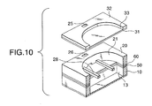
- Fig. 1 is an exploded perspective view to show an ink jet recording head according to a first embodiment of the invention.
- Figs. 2A and 2B are a plan view and a sectional view of the ink jet recording head shown in Fig. 1.
- a channel forming substrate 10 is made of a silicon monocrystalline substrate of a ⁇ 110> plane orientation in the embodiment.
- a substrate about 150-300 ⁇ m thick is used as the channel forming substrate 10; preferably a substrate about 180-280 ⁇ m thick, more preferably a substrate about 220 ⁇ m thick is used because the arrangement density can be made high while the rigidity of a partition between contiguous pressure generating chambers is maintained.
- the channel forming substrate 10 is formed on one face with an opening face and on an opposite face with an elastic film 50 of 1-2 ⁇ m thick made of silicon dioxide previously formed by thermal oxidation.
- the channel forming substrate 10 is formed on the opening face with pressure generating chambers 12 which are partitioned by a plurality of partitions 11 and are placed side by side in a width direction by anisotropically etching the silicon monocrystalline substrate and is formed on the outside in the longitudinal direction thereof with a communication section 13 communicating with a reservoir section of a reservoir forming substrate described later and forming a part of a reservoir 100 which becomes an ink chamber common to the pressure generating chambers 12; the communication section 13 communicates with one end part of each pressure generating chamber 12 in the longitudinal direction thereof via an ink supply port 14.
- the anisotropic etching is executed by using the nature that if the silicon monocrystalline substrate is immersed in an alkaline solution such as KOH, it gradually erodes, a first ⁇ 111> plane perpendicular to a ⁇ 110> plane and a second ⁇ 111> plane forming about 70 degrees with the first ⁇ 111> plane and forming about 35 degrees with the ⁇ 110> plane appear, and the etching rate of the ⁇ 111> plane is about 1/180 that of the ⁇ 110> plane.
- each pressure generating chamber 12 are formed by the first ⁇ 111> planes and the short sides are formed by the second ⁇ 111> planes.
- the pressure generating chambers 12 are formed by etching the silicon monocrystalline substrate almost passing through the channel forming substrate 10 to the elastic film 50. The amount of immersing the elastic film 50 in the alkaline solution for etching the silicon monocrystalline substrate is extremely small.
- Each ink supply port 14 communicating with one end of each pressure generating chamber 12 is formed shallower than the pressure generating chamber 12 for holding the flow passage resistance of ink flowing into the pressure generating chamber 12 constant. That is, the ink supply ports 14 are formed by etching the silicon monocrystalline substrate to an intermediate point in the thickness direction (half etching). The half etching is executed by adjusting the etching time.
- a nozzle plate 16 formed with nozzle orifices 15 communicating with the pressure generating chamber 12 on the opposite side of the pressure generating chamber 12 to the ink supply ports 14 is fixedly secured to the opening face side of the channel forming substrate 10 via an adhesive, a thermal-deposited film, etc.
- the nozzle plate 16 is made of glass ceramics, stainless steel, or the like having a thickness of 0.1-1 mm and a linear expansion coefficient of 2.5-4.5 [x 10 -6 /°C] at 300°C or less, for example.
- One face of the nozzle plate 16 covers fully one face of the channel forming substrate 10, namely, the nozzle plate 16 also serves as a reinforcing plate for protecting the silicon monocrystalline substrate from shock and external force.
- the nozzle plate 16 may be formed of a material having substantially the same thermal expansion coefficient as the channel forming substrate 10 has. In this case, the channel forming substrate 10 and the nozzle plate 16 become deformed substantially in the same manner due to heat and thus can be joined easily using a thermosetting adhesive, etc.
- each pressure generating chamber 12 for giving ink drop jet pressure to ink and the size of each nozzle orifice 15 for jetting ink drops are optimized in response to the jetted ink drop amount, jet speed, and jet frequency. For example, to record 360 ink drops per inch, the nozzle orifice 15 needs to be made accurately with a diameter of several ten ⁇ m.
- a lower electrode film 60 for example, about 0.2 ⁇ m thick
- a piezoelectric film 70 for example, about 1 ⁇ m thick
- an upper electrode film 80 for example, about 0.1 ⁇ m thick are deposited on the elastic film 50 on the opposite side to the opening face of the channel forming substrate 10 by a process described later, making up a piezoelectric element 300.
- This piezoelectric element 300 refers to the portion containing the lower electrode film 60, the piezoelectric film 70, and the upper electrode film 80.
- one electrode of the piezoelectric element 300 is used as a common electrode and the other electrode and the piezoelectric film 70 are patterned for each pressure generating chamber 12.
- a portion made up of the electrode and the piezoelectric film 70 patterned where piezoelectric distortion occurs as a voltage is applied to both electrodes is referred to as a piezoelectric active part 320.
- the lower electrode film 60 is used as the common electrode of the piezoelectric element 300 and the upper electrode film 80 is used as a discrete electrode of the piezoelectric element 300, but the lower electrode film 60 may be used as a discrete electrode and the upper electrode film 80 may be used as the common electrode for convenience of a drive circuit and wiring.
- the piezoelectric active part is formed for each pressure generating chamber 12.
- the piezoelectric element 300 and the diaphragm displaced by drive of the piezoelectric element 300 are collectively called a piezoelectric actuator.
- the elastic film 50 and the lower electrode film 60 act as the diaphragm, but the lower electrode film may also serve as the elastic film.
- a reservoir forming substrate 20 having a reservoir section 21 forming at least a part of the reservoir 100 is joined to the piezoelectric element 300 side of the channel forming substrate 10.
- the reservoir section 21 is formed in the width direction of the pressure generating chambers 12 piercing the reservoir forming substrate 20 in the thickness direction thereof and is made to communicate with the communication section 13 of the channel forming substrate 10 and forms a part of the reservoir 100 which becomes an ink chamber common to the pressure generating chambers 12 as described above.
- the reservoir forming substrate 20 is formed using a silicon monocrystalline substrate of the same material as the channel forming substrate 10, so that even if the reservoir forming substrate 20 and the channel forming substrate 10 are bonded at a high temperature using a thermosetting adhesive, they can be bonded reliably as in the case of the above-described nozzle plate 16. Therefore, the manufacturing process can be simplified.
- a compliance substrate 30 made up of a sealing film 31 and a fixing plate 32 is joined to the reservoir forming substrate 20.
- the sealing film 31 is made of a material having low rigidity and flexibility (for example, polyphenylene sulfide (PPS) film of 6 ⁇ m thick) and seals one side of the reservoir section 21.
- the fixing plate 32 is formed of a hard material of metal, etc., (for example, stainless steel (SUS) of 30 ⁇ m thick, or the like). Since the area of the fixing plate 32 opposed to the reservoir 100 forms an opening section 33 made by completely removing a part of the seal plate 32 in the thickness direction thereof, one side of the reservoir 100 is sealed only with the sealing film 31 having flexibility and becomes a flexible section 22 that can become deformed as internal pressure changes.
- An ink introduction port 25 for supplying ink to the reservoir 100 is formed on the compliance substrate 30 on the outside substantially at the center in the longitudinal direction of the reservoir 100. Further, the reservoir forming substrate 20 is formed with an ink introduction passage 26 for making the ink introduction port 25 and the side wall of the reservoir 100 communicate with each other.
- ink is supplied to the reservoir 100 through one ink introduction port 25 and one ink introduction passage 26, but the scope of the invention is not limited to it. For example, more than one ink introduction port and more than one ink introduction passage may be provided in response to any desired ink supply amount or the opening area of the ink introduction port may be enlarged for enlarging the ink flow passage.
- the area of the reservoir forming substrate 20 opposed to the piezoelectric element 300 is formed with a piezoelectric element holding section 24 capable of hermetically sealing the space, and at least the piezoelectric active part 320 of the piezoelectric element 300 is hermetically sealed in the piezoelectric element holding section 24.
- the piezoelectric element holding section 24 is formed in size covering a plurality of piezoelectric elements 300 placed side by side in a width direction.
- the reservoir forming substrate 20 forms the reservoir 100 and also serves as a capping member for insulating the piezoelectric elements 300 from the external environment; it can prevent the piezoelectric elements 300 from being destroyed due to the external environment of a moisture content, etc.
- the inside of the piezoelectric element holding section 24 is sealed.
- the space in the piezoelectric element holding section 24 is evacuated or is placed in a nitrogen or argon atmosphere, etc., whereby the inside of the piezoelectric element holding section 24 can be held at low humidity and destruction of the piezoelectric elements 300 can be prevented more reliably.
- the piezoelectric film 70 and the upper electrode film 80 of the piezoelectric element 300 thus hermetically sealed by means of the piezoelectric element holding section 24 are extended from one end part of the pressure generating chamber 12 in the longitudinal direction thereof to the outside of the reservoir forming substrate 20 on the channel forming substrate 10 and are connected to external wiring 40, such as a flexible cable, on an exposed portion 10a where the face of the joint side of the channel forming substrate 10 to the reservoir forming substrate 20 is exposed. That is, wiring is extended from the piezoelectric element 300 to the outside of the reservoir forming substrate 20, whereby the piezoelectric element 300 and the external wiring can be connected easily.
- external wiring 40 such as a flexible cable
- ink is taken in through the ink introduction port 25 connected to external ink supply means (not shown) and the inside of the recording head from the reservoir 100 to the nozzle orifices 15 is filled with ink, then a voltage is applied to the part between the lower electrode film 60 and the upper electrode film 80 corresponding to each pressure generating chamber 12 according to a record signal from an external drive circuit (not shown) for deflection-deforming the elastic film 50, the lower electrode film 60, and the piezoelectric film 70, thereby raising pressure in the corresponding pressure generating chamber 12 and jetting an ink drop through the corresponding nozzle orifice 15.
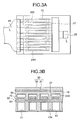
- the piezoelectric element holding section 24 of the reservoir forming substrate 20 is formed so as to cover all piezoelectric elements 300 placed side by side in the width direction, but the scope of the invention is not limited to it.
- the scope of the invention is not limited to it. For example, as shown in Figs.
- the piezoelectric element holding section 24 may be divided by partition walls 27 into separate piezoelectric element holding sections 24A for hermetically sealing the piezoelectric elements 300 with the corresponding piezoelectric element holding sections 24A, whereby the partition wall 27 is joined to the portion of the channel forming substrate 10 corresponding to a side wall 12a of each pressure generating chamber 12, the rigidity of the peripheral wall of the pressure generating chamber 12 is enhanced, and falling down of the peripheral wall when the piezoelectric element 300 is driven can be suppressed. According to the composition, destruction of the piezoelectric element 300 can also be prevented as in the above-described embodiment, needless to say.
- the piezoelectric film 70 and the upper electrode film 80 are extended to the outside of the reservoir forming substrate 20 and the upper electrode film 80 and the external wiring 40 are connected, but the scope of the invention is not limited to it.
- the piezoelectric elements 300 may be patterned in the area facing the pressure generating chambers 12 and a lead electrode 90 may be extended from the upper electrode film 80 via an insulation film 85 to the exposed portion 10a outside the reservoir forming substrate 20 and be connected to the external wiring 40 in the proximity of the end portion thereof.
- the lead electrode 90 is extended from the upper electrode film 80 to the outside of the reservoir forming substrate 20 and is connected to the external wiring 40, whereby a gap with the elastic film 50 when the reservoir forming substrate 20 is bonded becomes only several ⁇ m and the piezoelectric elements 300 can be hermetically sealed in the piezoelectric element holding section 24 more reliably.
- the channel forming substrate 10 is so formed as to be larger than the reservoir forming substrate 20 and the piezoelectric elements 300 and the external wiring 40 are connected on the exposed portion 10a of the channel forming substrate 10, but the scope of the invention is not limited to it.
- the reservoir forming substrate 20 may be so formed as to be larger than the channel forming substrate 10
- the face on the joint side of the reservoir forming substrate 20 to the channel forming substrate 10 may be exposed to form an exposed portion 20a
- the piezoelectric elements 300 and the external wiring may be connected on the exposed portion 20a.
- the communication section 13 forming a part of the reservoir 100 via the ink supply ports 14 is placed on the end part side of the channel forming substrate 10 opposite to the nozzle orifices 15 of the pressure generating chambers 12, but the scope of the invention is not limited to it.
- the reservoir 100 basically may be formed only of the reservoir section 21 of the reservoir forming substrate 20, and the pressure generating chambers 12 and the reservoir 100 may be made to communicate with each other via a communication passage 18 relatively narrower than the flow passage of the reservoir 100 in the channel forming substrate 10.
- the composition when ink is supplied to the pressure generating chamber 12, the flow velocity of the ink is maintained, so that mixing of bubbles can be prevented and good ink jetting can be executed.
- Figs. 7A and 7B are a plan view and a sectional view of an ink jet recording head according to a second embodiment of the invention.
- the second embodiment is an example wherein a flexible section 22 is placed in a channel forming substrate 10 rather than in the area of a reservoir section 21 opposite to the channel forming substrate 10.
- the channel forming substrate 10 in the area corresponding to the reservoir section 21 is formed with a through section 18 not communicating with pressure generating chambers in the width direction of the pressure generating chambers, and at least the space between the through section 18 and the reservoir section 21 is closed with a flexible film 110 that can be elastically deformed in the thickness direction thereof, forming the flexible section 22.
- SUS stainless steel
- the flexible film 110 becomes elastically deformed, thereby absorbing the pressure change, whereby the internal pressure of the reservoir 100 is always suppressed to a given value or less and a good ink jet characteristic is maintained.
- an elastic film 50 and a lower electrode film 60, a piezoelectric film 70, and an upper electrode film 80 making up the piezoelectric element 300 are placed on the channel forming substrate 10 in the area corresponding to the reservoir section 21, and become the flexible film 110 in the area facing the through section 18.
- the flexible film 110 made up of the films is about 3 ⁇ m thick and functions sufficiently as a compliance section.
- the flexible film 110 contains a film having a tensile stress in all plane direction.
- the stress of the whole films making up the flexible film 110 is strong in the tensile direction and does not buckle, so that excessive deformation of the flexible film 110 is suppressed and destruction of the flexible film 110 can be prevented.
- the flexible film 110 is made up only of the elastic film 50 and the films making up the piezoelectric element 300 and can be formed as the piezoelectric element 300 is formed.
- the through section 18 can also be etched together with the pressure generating chambers 12 and be formed and thus can be formed easily without increasing the manufacturing steps.
- the flexible film 110 consists of the elastic film 50, the lower electrode film 60, the piezoelectric film 70, and the upper electrode film 80, but the scope of the invention is not limited to it.
- the flexible film 110 may be made up of the elastic film 50 and at least one of the layers making up the piezoelectric element 300; in any way, it may be a film having flexibility and a predetermined strength.
- the elastic film is formed of silicon dioxide as in the embodiment, if the flexible film 110 is made only of an elastic film, a low strength is provided; the composition is not preferred.
- a separate film made of any other material may be provided as the flexible film 110, needless to say.
- Figs. 8A and 8B are a sectional view of the main part of an ink jet recording head and a schematic diagram of a flexible film according to a third embodiment of the invention.
- the third embodiment is similar to the second embodiment except that a beam member 111 made up of projection bars extended in a plane direction is provided on the surface on the channel forming substrate side of a flexible film 110 which becomes a flexible section 22.
- the beam member 111 is provided for enhancing the strength of the flexible film 110.
- the beam member 111 is provided like a grid over the whole surface of the flexible film 110 as shown in Fig. 8B.
- the area of the flexible film 110 may be determined appropriately in response to the conditions of the material, film thickness, etc., of the flexible film 110 so as to provide any desired strength for the flexible film 110.
- the portion of the flexible film 110 which becomes the actual flexible part where the beam member 111 is not formed holds an area at least 10 times the area of a pressure generating chamber.
- the formation method of the beam member 111 is not limited; for example, to make a through section 18 in a channel forming substrate 10, a predetermined mask pattern is used for etching, whereby a portion where a part of the channel forming substrate 10 is left may be used as the beam member 111.
- the flexible film 110 is provided with the beam member 111, whereby the strength of the flexible film 110 can be increased. Therefore, the strength and compliance of the flexible film 110 can be adjusted easily and with high accuracy by adjusting the area of the beam member 111.
- the form of the beam member 111 is not limited to a grid; it may be any other form, such as a slanting grid, if the form is capable of holding predetermined compliance.
- the strength and compliance of the flexible film 110 may be adjusted by changing the size of the through section 18.
- Figs. 9A and 9B are a plan view and a sectional view of an ink jet recording head according to a fourth embodiment of the invention.
- the fourth embodiment is similar to the first embodiment except that a reservoir section 21 forming a part of a reservoir 100 is formed with a reinforcing member 28 for holding the rigidity of a reservoir forming substrate 20.
- the reservoir section 21 is defined in the reservoir forming substrate 20 and at least one reinforcing member 28 (for example, two beam-like reinforcing members 28 in the embodiment) is placed between side walls facing each other.
- the reinforcing member 28 is formed along the longitudinal direction of a piezoelectric element 300 on the surface side opposite to the joint face of the reservoir section 21 to a channel forming substrate 10:
- the reinforcing member 28 is formed by half-etching the reservoir forming substrate 20 from the joint face side to the channel forming substrate 10, and is thinner than other portions.
- the reinforcing member 28 is made an area as wide as possible in the area range to such an extent that a flexible section 22 is capable of uniformly holding the internal pressure of the reservoir 100.
- the beam-like reinforcing members 28 are placed between the side walls defining the reservoir 100 and the rigidity of the reservoir section 21 is enhanced.
- the volume of the reservoir section 21 is made relatively large, deformation such as a warp of the reservoir forming substrate caused by a thermal stress at the installation time can be prevented and a crack of the reservoir forming substrate caused by the deformation can be prevented. Therefore, the durability and reliability of the head can be enhanced.
- the reinforcing members 28 are formed on the surface side opposite to the joint face of the reservoir forming substrate 20 to the channel forming substrate 10, but the scope of the invention is not limited to it.
- the reinforcing members 28 may be formed on the joint face side of the reservoir forming substrate 20 to the channel forming substrate 10.
- the whole reinforcing member 28 is made thinner than other portions, but the scope of the invention is not limited to it.
- the reinforcing member 28 basically may be formed with the same thickness as the reservoir forming substrate 20 and a part of the joint face side to the channel forming substrate 10 may be made a removal part 28a provided by removing a part in the thickness direction.
- the two reinforcing members 28 are provided, but the scope of the invention is not limited to it.
- one or three or more reinforcing members 28 may be provided.
- the form of the reinforcing member 28 may be a form capable of holding the compliance of the flexible section 22 to such an extent that internal pressure change of the reservoir 100 can be absorbed.
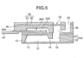
- Fig. 12 is a sectional view of the main part of an ink jet recording head according to a fifth embodiment of the invention.
- the fifth embodiment is an example wherein a compliance substrate 30A made of one member is placed on a channel forming substrate 10. That is, as shown in Fig. 12, the fifth embodiment is similar to the first embodiment except that a through hole which becomes an ink introduction port 25 is made on the outside of a flexible section 22A having flexibility provided by removing a part of the area facing a reservoir 100 in the thickness direction of the area.
- the material of the compliance substrate 30A is a resin material having flexibility, such as fluororesin, silicone family resin, or silicone rubber, so that the compliance substrate 30A can be formed easily.
- the manufacturing method of the compliance substrate 30A is not limited; for example, the compliance substrate 30A can be formed by forming a resin layer of a predetermined thickness on a silicon monocrystalline substrate forming a reservoir forming substrate 20, then forming the reservoir 100, etc., on the reservoir forming substrate 20 by etching, etc., and further etching a part, etc., in the thickness direction of the area of the resin layer opposed to the reservoir 100.
- the compliance substrate 30A is formed of a resin material, but the scope of the invention is not limited to it.
- a compliance substrate 30B may be made of a thin film of metal, ceramic, or the like about 1-10 ⁇ m thick.
- the area opposed to the reservoir 100 can be made a flexible section 22B having flexibility without removing a part in the thickness direction. Therefore, the head can be manufactured more easily.
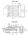
- Figs. 14A and 14B are a plan view and a sectional view of an ink jet recording head according to a sixth embodiment of the invention.
- the sixth embodiment is similar to the first embodiment except that a detection through hole 24a for detecting displacement of each piezoelectric element 300 is made so as to across the pressure generating chambers 12 in such portion corresponding to the piezoelectric elements 300 in such area of a reservoir forming substrate 20 opposed to a piezoelectric element holding section 24.
- each piezoelectric element 300 can be checked, for example, using laser beam, etc., before a compliance substrate 30 is joined onto the reservoir forming substrate 20. Therefore, a failure of the piezoelectric element 300 can be found before the head is completed; the head manufacturing efficiency can be enhanced. Since the detection through hole 24a is sealed with the compliance substrate 30, the piezoelectric element holding section 24 can be held in a hermetic seal state as in the first embodiment.
- the detection through hole 24a is not limited in size and may be formed at least in the area facing the piezoelectric elements 300. Therefore, in the embodiment, it is made like a groove in the row direction of the pressure generating chambers 12. However, for example, the detection through hole 24a may be made a round hole for each piezoelectric element 300 or the whole piezoelectric element holding section may be made the through hole.
- the detection through hole 24a is sealed with the compliance substrate 30, but the scope of the invention is not limited to it.
- the detection through hole 24a may be sealed only with a sealing film 31 having flexibility, namely, a fixing plate 32 in the area facing the detection through hole 24a may be removed to form a flexible section 22C.
- the sealing film 31 which becomes the flexible section 22C of the piezoelectric element holding section 24 may be formed of a light transparent member, such as acrylic resin, so that displacement of each piezoelectric element 300 can be detected with the piezoelectric element 300 hermetically sealed in the piezoelectric element holding section 24. That is, the piezoelectric elements 300 can be inspected at all times.
- Figs. 16A and 16B are a plan view and a sectional view of an ink jet recording head according to a seventh embodiment of the invention.
- the seventh embodiment is another example of the wiring method of a piezoelectric element 300.
- a compliance substrate 30 is not placed in a part on the opposite side of a reservoir forming substrate 20 to a reservoir 100 to form an exposed portion 20b where the surface of the reservoir forming substrate 20 is exposed.
- Wiring 29 is extended onto the exposed portion 20b of the reservoir forming substrate 20 by wire bonding from an upper electrode film 80 of the piezoelectric element 300 extended to the outside of the reservoir forming substrate 20, and the end part of the extended wiring 29 is made an installation section 120 for connecting the piezoelectric element 300 and external wiring 40.
- the outside is molded by an insulating member 95 of epoxy, etc., for example, for providing electric insulation.
- the seventh embodiment is similar to the first embodiment in other points.
- the exposed portion requires a width of about 2.2-3.0 mm and the dimensions of the head become a little large.
- the wiring 29 is extended onto the exposed portion 20b of the reservoir forming substrate 20 by wire bonding from an exposed portion 10a of a channel forming substrate 10 and is connected to the external wiring 40.
- the exposed portion 10a of the channel forming substrate 10 can be made about 0.2 mm wide and the dimensions of the recording head can be made smaller.
- advantages similar to those of the first embodiment can also be provided.
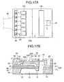
- Figs. 17A and 17B are a plan view and a sectional view of an ink jet recording head according to an eighth embodiment of the invention.
- the eighth embodiment is an example wherein a reservoir forming substrate 20 is formed with a through groove via which a piezoelectric element 300 and external wiring are connected.
- a piezoelectric film 70 and an upper electrode film 80 of the piezoelectric element 300 are extended to the top of the peripheral wall of a pressure generating chamber 12 in the longitudinal direction thereof on the side of a nozzle orifice 15 and are sandwiched between a channel forming substrate 10 and the reservoir forming substrate 20.
- a part of the joint face of the reservoir forming substrate 20 to a compliance substrate 30 is made an exposed portion 20b provided by exposing the surface as in the seventh embodiment, and a through groove 35 extended in the direction in which the pressure generating chambers 12 are placed side by side is formed in the area corresponding to the exposed portion 20b and facing the upper electrode film 80 of the piezoelectric element 300.
- Wiring 29 is extended by wire bonding onto the surface of the reservoir forming substrate 20 through the through groove 35 from the upper electrode film 80 of each piezoelectric element 300, and the end part of the wiring 29 is made an installation section 120 for connecting the piezoelectric element 300 and external wiring 40 such as a flexible cable.
- the wiring 29 is extended via the through groove 35, thus eliminating the need for providing the exposed portion 10a at the end of the channel forming substrate 10 or the exposed portion 20a at the end portion of the reservoir forming substrate 20; the head can be more miniaturized.
- the through groove 35 is formed like a groove over the row of the piezoelectric elements 300, but the scope of the invention is not limited to it.
- a through hole may be made separately for each piezoelectric element 300.
- the wiring 29 is extended by wire bonding from the upper electrode film 80, but the scope of the invention is not limited to it.
- a conductive thin film of gold (Au), etc. may be formed on the inner peripheral surface of the through groove 35 and on the top of the compliance substrate 30 and may be patterned for each piezoelectric element 300, thereby providing wiring 29A.
- wiring 29B may be extended via a joint face 20c and an outer face 20d of the reservoir forming substrate 20 to the exposed portion 20b of the piezoelectric element 300 and the end part of the wiring 29B may be made the installation section 120 for connecting to the external wiring 40.
- a lead electrode 90 is extended from the upper electrode film 80 to the joint face 20c of the reservoir forming substrate 20 and the upper electrode film 80 and the wiring 29B are joined via the lead electrode 90, as shown in the figures, whereby a gap with an elastic film 50 when the reservoir forming substrate 20 is bonded becomes only several ⁇ m and the piezoelectric elements 300 can be hermetically sealed in a piezoelectric element holding section 24 more reliably, as described above.
- Figs. 20A and 20B are a plan view and a sectional view of the main part of an ink jet recording head according to a ninth embodiment of the invention.
- a channel forming substrate 10 is formed with two rows of pressure generating chambers 12 placed side by side in the width direction thereof so that the end parts of the pressure generating chambers 12 on the side of nozzle orifices 15 in one row are opposed to those in the other, and a piezoelectric element 300 is formed in the area corresponding to each pressure generating chamber 12.
- a reservoir 100 is provided for each row of the pressure generating chambers 12 on the outside in the longitudinal direction of the pressure generating chambers 12 and an ink introduction port 25 and an ink introduction passage 26 are made to communicate with each reservoir 100.
- the structures of the reservoir, the ink introduction port, etc. are similar to those in the above-described embodiments.
- Each piezoelectric element 300 is extended from the area facing the corresponding pressure generating chamber 12 to the top of the peripheral wall on the side of the reservoir 100 and is sandwiched between the channel forming substrate 10 and a reservoir forming substrate 20.
- a through groove 35 is provided for each row of the pressure generating chambers 12 on the side of a reservoir section 21 of the reservoir forming substrate 20, namely, in the area facing an upper electrode film 80 of the piezoelectric element 300 in the area facing the peripheral wall of the pressure generating chamber 12.
- a drive circuit 130 for driving the piezoelectric elements 300 is mounted on the reservoir forming substrate 20 in the area corresponding to the space between the rows of the pressure generating chambers 12.
- the drive circuit 130 may be a circuit board or a semiconductor integrated circuit (IC) containing the drive circuit.
- the upper electrode film 80 of each piezoelectric element 300 and the drive circuit 130 are connected by wiring 29 extended by wire bonding, etc., through the through groove 35.
- wiring 29D for supplying a signal to the drive circuit 130 is placed on the reservoir forming substrate 20 and is connected at one end to the drive circuit 130 and an opposite end of the wiring 29D forms an installation section 120 to which external wiring 40 is connected.
- the head can also be miniaturized as in the eighth embodiment.
- the through groove 35 is made on the side of the reservoir 100, so that piezoelectric elements 300, the drive circuit 130, and the like can be connected more efficiently between the rows of the pressure generating chambers 12.
- the drive circuit 130 is placed on the reservoir forming substrate 20, but the scope of the invention is not limited to it.
- the wiring extended from the piezoelectric element 300 and the external wiring such as a flexible cable may be connected on an exposed portion 10a of the reservoir forming substrate 20 as in the first embodiment, needless to say.
- the upper electrode films 80 of the piezoelectric elements 300 and the drive circuit 130 are connected by the wiring 29 extended only by wire bonding, but the scope of the invention is not limited to it.
- an IC wiring section 140 made of a thin film may be placed in the area between the drive circuit 130 on the reservoir forming substrate 20 and the through groove 35 and each piezoelectric element 300 and the drive circuit 130 may be connected via the IC wiring section 140. That is, wiring 29E may be extended by wire bonding from the upper electrode film 80 of each piezoelectric element 300 to one end part of the IC wiring section 140 and the drive circuit 130 may be connected by wire bonding to an opposite end part of the IC wiring section 140.
- the wiring 29E is extended by wire bonding from the upper electrode film 80 to the IC wiring section 140, but the scope of the invention is not limited to it.
- a conductive thin film of gold (Au), etc. may be formed on the inner peripheral surface of the through groove 35 and on the top of the reservoir forming substrate 20 and may be patterned for each piezoelectric element 300, thereby providing the wiring 29E.
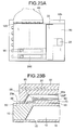
- Figs. 23A and 23B are a plan view and a sectional view of the main part of an ink jet recording head according to a tenth embodiment of the invention.
- the tenth embodiment is an example wherein an installation section 120 is placed in an exposed portion 10b on one end part side of a channel forming substrate 10 in the direction in which piezoelectric elements 300 are placed side by side.
- each piezoelectric element 300 is placed in the area facing each pressure generating chamber 12 and a lead electrode 90 is extended from an upper electrode film 80 to the area facing a joint face 20c of a reservoir forming substrate 20.
- Wiring 29F is placed on the joint face 20c of the reservoir forming substrate 20 and an inner face 20e of a piezoelectric element holding section 24, and the lead electrode 90 and the installation section 120 are connected.
- the tenth embodiment is similar to the first embodiment in other points.
- the route of the wiring 29F is not limited; when the reservoir forming substrate 20 is bonded with an adhesive, etc., the wiring 29F, the end part of each lead electrode 90, and one end of the installation section 120 may be connected.
- external wiring 40 can be drawn out from one end part in the width direction of the pressure generating chamber 12, so that it is made possible to arrange a plurality of recording heads horizontally.
- the reservoir forming substrate 20 having the reservoir section 21 forming a part of the reservoir 100 as the reservoir forming member is joined to one side of the channel forming substrate 10, but the scope of the invention is not limited to it.
- the reservoir forming member may adopt a structure wherein a plurality of substrates are used to form the reservoir.
- the nozzle plate 16 is joined as the reservoir forming member, but the scope of the invention is not limited to it.
- a multi-layer structure containing another substrate having nozzle communication holes, etc., to allow nozzle orifices and pressure generating chambers to communicate with each other may be adopted.
- ink jet recording heads of thin film type that can be manufactured by applying the film formation and lithography process are taken as examples, but the scope of the invention is not limited to them.
- the invention can also be adopted for ink jet recording heads of thick film type formed by a method of putting a green sheet or the like.
- Each of the ink jet recording heads of the embodiments forms a part of a recording head unit comprising an ink flow passage communicating with an ink cartridge, etc., and is installed in an ink jet recording apparatus.
- Fig. 24 is a schematic diagram to show an example of the ink jet recording apparatus.
- cartridges 2A and 2B constituting an ink supply member are detachably placed in recording head units 1A and 1B each having an ink jet recording head, and a carriage 3 on which the recording head units 1A and 1B are mounted is placed axially movably on a carriage shaft 5 attached to a recorder main body 4.
- the recording head units 1 A and 1 B jet a black ink composite and a color ink composite respectively, for example.
- the driving force of a drive motor 6 is transmitted to the carriage 3 via a plurality of gears (not shown) and a timing belt (not shown), whereby the carriage 3 on which the recording head units 1A and 1B are mounted is moved along the carriage shaft 5.
- the recorder main body 4 is provided with a platen 8 along the carriage shaft 5.
- a recording sheet S of a recording medium such as paper fed by a paper feed roller, etc., (not shown) is wrapped around the platen 8 and is transported.
- the reservoir forming substrate forming at least a part of the reservoir is joined onto the channel forming substrate for forming the reservoir, thus the structure of the head can be simplified; the manufacturing process can be decreased and the manufacturing costs can be reduced. Since the reservoir forming substrate also serves as the capping member for insulating the piezoelectric elements from the outside, the piezoelectric elements can be prevented from being destroyed due to the external environment, and the durability can be improved. Further, the piezoelectric elements and the external wiring are connected on the reservoir forming substrate, whereby the head can be miniaturized.
Applications Claiming Priority (11)
| Application Number | Priority Date | Filing Date | Title |
|---|---|---|---|
| JP23524998 | 1998-08-21 | ||
| JP23524998 | 1998-08-21 | ||
| JP23982598 | 1998-08-26 | ||
| JP23982598 | 1998-08-26 | ||
| JP29977998 | 1998-10-21 | ||
| JP29977998 | 1998-10-21 | ||
| JP3459299 | 1999-02-12 | ||
| JP3459299 | 1999-02-12 | ||
| JP22206299 | 1999-08-05 | ||
| JP22206299A JP3422364B2 (ja) | 1998-08-21 | 1999-08-05 | インクジェット式記録ヘッド及びインクジェット式記録装置 |
| EP99116295A EP0985535B1 (de) | 1998-08-21 | 1999-08-18 | Tintenstrahlaufzeichnungskopf und diesen enthaltendes Tintenstrahlaufzeichnungsgerät |
Related Parent Applications (1)
| Application Number | Title | Priority Date | Filing Date |
|---|---|---|---|
| EP99116295A Division EP0985535B1 (de) | 1998-08-21 | 1999-08-18 | Tintenstrahlaufzeichnungskopf und diesen enthaltendes Tintenstrahlaufzeichnungsgerät |
Publications (3)
| Publication Number | Publication Date |
|---|---|
| EP1277583A2 true EP1277583A2 (de) | 2003-01-22 |
| EP1277583A3 EP1277583A3 (de) | 2003-03-05 |
| EP1277583B1 EP1277583B1 (de) | 2005-05-11 |
Family
ID=27521622
Family Applications (2)
| Application Number | Title | Priority Date | Filing Date |
|---|---|---|---|
| EP02022353A Expired - Lifetime EP1277583B1 (de) | 1998-08-21 | 1999-08-18 | Tintenstrahlaufzeichnungskopf und diesen enthaltendes Tintenstrahlaufzeichnungsgerät |
| EP99116295A Expired - Lifetime EP0985535B1 (de) | 1998-08-21 | 1999-08-18 | Tintenstrahlaufzeichnungskopf und diesen enthaltendes Tintenstrahlaufzeichnungsgerät |
Family Applications After (1)
| Application Number | Title | Priority Date | Filing Date |
|---|---|---|---|
| EP99116295A Expired - Lifetime EP0985535B1 (de) | 1998-08-21 | 1999-08-18 | Tintenstrahlaufzeichnungskopf und diesen enthaltendes Tintenstrahlaufzeichnungsgerät |
Country Status (4)
| Country | Link |
|---|---|
| EP (2) | EP1277583B1 (de) |
| JP (1) | JP3422364B2 (de) |
| AT (2) | ATE295265T1 (de) |
| DE (2) | DE69917849T2 (de) |
Cited By (4)
| Publication number | Priority date | Publication date | Assignee | Title |
|---|---|---|---|---|
| EP1518685A1 (de) * | 2003-09-29 | 2005-03-30 | Brother Kogyo Kabushiki Kaisha | Flüssigkeitstrahlvorrichtung und Herstellungsverfahren dafür |
| WO2005044573A2 (en) * | 2003-10-31 | 2005-05-19 | Hewlett-Packard Development Company, L.P. | Fluid ejection device with insulating feature |
| EP1884294A2 (de) * | 2006-08-01 | 2008-02-06 | Brother Kogyo Kabushiki Kaisha | Flüssigkeitstransportvorrichtung und Verfahren zur Herstellung einer Flüssigkeitstransportvorrichtung |
| CN103112253A (zh) * | 2011-11-10 | 2013-05-22 | 施乐公司 | 用于高密度印刷头的粘合硅结构 |
Families Citing this family (35)
| Publication number | Priority date | Publication date | Assignee | Title |
|---|---|---|---|---|
| JP2001353871A (ja) | 2000-04-12 | 2001-12-25 | Seiko Epson Corp | インクジェット式記録ヘッド |
| JP2003053966A (ja) * | 2000-06-12 | 2003-02-26 | Seiko Epson Corp | インクジェット式記録ヘッド |
| JP2002316417A (ja) * | 2001-02-19 | 2002-10-29 | Seiko Epson Corp | インクジェット式記録ヘッド及びインクジェット式記録装置 |
| JP2003080705A (ja) * | 2001-09-13 | 2003-03-19 | Seiko Epson Corp | インクジェット式記録ヘッド及びその製造方法並びにインクジェット式記録装置 |
| JP4585721B2 (ja) * | 2001-09-13 | 2010-11-24 | セイコーエプソン株式会社 | インクジェット式記録ヘッドの製造方法 |
| JP2003159800A (ja) * | 2001-09-13 | 2003-06-03 | Seiko Epson Corp | 液体噴射ヘッド及び液体噴射装置 |
| JP4484821B2 (ja) * | 2003-05-06 | 2010-06-16 | セイコーエプソン株式会社 | 液体噴射ヘッド及び液体噴射装置 |
| US7618130B2 (en) | 2003-05-06 | 2009-11-17 | Seiko Epson Corporation | Liquid jet head and liquid jet apparatus |
| JP4492051B2 (ja) * | 2003-07-17 | 2010-06-30 | セイコーエプソン株式会社 | 液体噴射ヘッドの製造方法 |
| JP4492520B2 (ja) | 2005-01-26 | 2010-06-30 | セイコーエプソン株式会社 | 液滴吐出ヘッドおよび液滴吐出装置。 |
| JP5023488B2 (ja) | 2005-03-09 | 2012-09-12 | セイコーエプソン株式会社 | デバイス実装構造とデバイス実装方法、液滴吐出ヘッド及び駆動ユニット並びに半導体装置 |
| JP2007045129A (ja) | 2005-08-12 | 2007-02-22 | Seiko Epson Corp | 液体噴射ヘッド及び液体噴射装置 |
| JP4779636B2 (ja) * | 2005-12-20 | 2011-09-28 | セイコーエプソン株式会社 | 液滴吐出ヘッド及び液滴吐出装置 |
| KR100818282B1 (ko) | 2006-10-26 | 2008-04-01 | 삼성전자주식회사 | 잉크젯 프린트헤드 |
| JP5067946B2 (ja) * | 2008-09-02 | 2012-11-07 | 富士フイルム株式会社 | 液体吐出ヘッド及び液体吐出ヘッドの製造方法 |
| DE102009028909A1 (de) | 2009-08-26 | 2011-03-17 | Nanoplus Gmbh Nanosystems And Technologies | Halbleiterlaser mit auf einem Laserspiegel angebrachtem Absorber |
| KR20120012160A (ko) * | 2010-07-30 | 2012-02-09 | 삼성전기주식회사 | 잉크젯 헤드 어셈블리 및 그 제조방법 |
| JP6024171B2 (ja) * | 2012-04-13 | 2016-11-09 | セイコーエプソン株式会社 | 液体噴射ヘッド及び液体噴射装置並びにアクチュエーター |
| JP6168385B2 (ja) * | 2013-01-23 | 2017-07-26 | 株式会社リコー | 粒子製造装置及び粒子製造方法 |
| JP6029497B2 (ja) * | 2013-03-12 | 2016-11-24 | エスアイアイ・プリンテック株式会社 | 液体噴射ヘッド及び液体噴射装置 |
| JP6061088B2 (ja) | 2013-03-28 | 2017-01-18 | セイコーエプソン株式会社 | 液体噴射ヘッド及び液体噴射装置 |
| JP2015033799A (ja) * | 2013-08-09 | 2015-02-19 | セイコーエプソン株式会社 | 液体噴射ヘッド、および、液体噴射装置 |
| JP6201584B2 (ja) | 2013-09-30 | 2017-09-27 | ブラザー工業株式会社 | 液滴噴射装置及び液滴噴射装置の製造方法 |
| JP6307890B2 (ja) * | 2014-01-17 | 2018-04-11 | セイコーエプソン株式会社 | 流路ユニット、液体噴射ヘッド、液体噴射装置 |
| JP6337637B2 (ja) * | 2014-06-18 | 2018-06-06 | 株式会社リコー | 液体吐出ヘッド及び画像形成装置 |
| JP6493676B2 (ja) * | 2015-06-05 | 2019-04-03 | セイコーエプソン株式会社 | 液体噴射装置及び液体噴射方法 |
| JP6648459B2 (ja) * | 2015-09-25 | 2020-02-14 | セイコーエプソン株式会社 | 液体噴射ヘッドおよび液体噴射装置 |
| JP7013124B2 (ja) * | 2016-01-08 | 2022-01-31 | キヤノン株式会社 | 液体吐出ヘッドの製造方法 |
| JP6859600B2 (ja) * | 2016-03-28 | 2021-04-14 | セイコーエプソン株式会社 | 液体噴射ヘッド、液体噴射ヘッドユニット、液体噴射装置及び液体噴射ヘッドユニットの製造方法 |
| JP6443774B2 (ja) * | 2017-07-03 | 2018-12-26 | 株式会社リコー | 粒子製造方法 |
| JP7106828B2 (ja) * | 2017-09-13 | 2022-07-27 | セイコーエプソン株式会社 | 液体噴射ヘッド、液体噴射装置、圧電デバイス、及び、液体噴射ヘッドの製造方法 |
| JP6409944B2 (ja) * | 2017-11-20 | 2018-10-24 | セイコーエプソン株式会社 | 液体噴射ヘッドおよび液体噴射装置 |
| JP7224782B2 (ja) * | 2018-05-30 | 2023-02-20 | キヤノン株式会社 | 液体吐出ヘッドおよびその製造方法 |
| JP7237480B2 (ja) * | 2018-06-29 | 2023-03-13 | キヤノン株式会社 | 液体吐出ヘッドおよびその製造方法 |
| JP7388028B2 (ja) | 2019-07-26 | 2023-11-29 | ブラザー工業株式会社 | 液体吐出ヘッド |
Citations (2)
| Publication number | Priority date | Publication date | Assignee | Title |
|---|---|---|---|---|
| JPH03243357A (ja) * | 1990-02-20 | 1991-10-30 | Sharp Corp | インクジェット記録ヘッド |
| EP0707961A2 (de) * | 1994-10-17 | 1996-04-24 | Seiko Epson Corporation | Mehrschichtiger Tintenstrahlaufzeichnungskopf und Verfahren zur Herstellung desselben |
Family Cites Families (3)
| Publication number | Priority date | Publication date | Assignee | Title |
|---|---|---|---|---|
| JPH05286131A (ja) * | 1992-04-15 | 1993-11-02 | Rohm Co Ltd | インクジェットプリントヘッドの製造方法及びインクジェットプリントヘッド |
| JPH07329292A (ja) * | 1994-04-13 | 1995-12-19 | Seiko Epson Corp | インクジェット式記録ヘッド |
| DE69624282T2 (de) * | 1995-04-19 | 2003-07-03 | Seiko Epson Corp | Tintenstrahlaufzeichnungskopf und Verfahren zu dessen Herstellung |
-
1999
- 1999-08-05 JP JP22206299A patent/JP3422364B2/ja not_active Expired - Fee Related
- 1999-08-18 EP EP02022353A patent/EP1277583B1/de not_active Expired - Lifetime
- 1999-08-18 AT AT02022353T patent/ATE295265T1/de not_active IP Right Cessation
- 1999-08-18 AT AT99116295T patent/ATE268693T1/de not_active IP Right Cessation
- 1999-08-18 EP EP99116295A patent/EP0985535B1/de not_active Expired - Lifetime
- 1999-08-18 DE DE69917849T patent/DE69917849T2/de not_active Expired - Lifetime
- 1999-08-18 DE DE69925318T patent/DE69925318T2/de not_active Expired - Lifetime
Patent Citations (2)
| Publication number | Priority date | Publication date | Assignee | Title |
|---|---|---|---|---|
| JPH03243357A (ja) * | 1990-02-20 | 1991-10-30 | Sharp Corp | インクジェット記録ヘッド |
| EP0707961A2 (de) * | 1994-10-17 | 1996-04-24 | Seiko Epson Corporation | Mehrschichtiger Tintenstrahlaufzeichnungskopf und Verfahren zur Herstellung desselben |
Non-Patent Citations (1)
| Title |
|---|
| PATENT ABSTRACTS OF JAPAN vol. 016, no. 034 (M-1204), 28 January 1992 (1992-01-28) & JP 03 243357 A (SHARP CORP), 30 October 1991 (1991-10-30) * |
Cited By (12)
| Publication number | Priority date | Publication date | Assignee | Title |
|---|---|---|---|---|
| EP1518685A1 (de) * | 2003-09-29 | 2005-03-30 | Brother Kogyo Kabushiki Kaisha | Flüssigkeitstrahlvorrichtung und Herstellungsverfahren dafür |
| CN1325261C (zh) * | 2003-09-29 | 2007-07-11 | 兄弟工业株式会社 | 液体输送装置及其制造方法 |
| US7461926B2 (en) | 2003-09-29 | 2008-12-09 | Brother Kogyo Kabushiki Kaisha | Liquid delivering apparatus and method of producing the same |
| US7992971B2 (en) | 2003-09-29 | 2011-08-09 | Brother Kogyo Kabushiki Kaisha | Liquid delivering apparatus and method of producing the same |
| WO2005044573A2 (en) * | 2003-10-31 | 2005-05-19 | Hewlett-Packard Development Company, L.P. | Fluid ejection device with insulating feature |
| US7229152B2 (en) | 2003-10-31 | 2007-06-12 | Hewlett-Packard Development Company, L.P. | Fluid ejection device with insulating feature |
| WO2005044573A3 (en) * | 2003-10-31 | 2008-01-24 | Hewlett Packard Development Co | Fluid ejection device with insulating feature |
| EP1884294A2 (de) * | 2006-08-01 | 2008-02-06 | Brother Kogyo Kabushiki Kaisha | Flüssigkeitstransportvorrichtung und Verfahren zur Herstellung einer Flüssigkeitstransportvorrichtung |
| EP1884294A3 (de) * | 2006-08-01 | 2009-05-27 | Brother Kogyo Kabushiki Kaisha | Flüssigkeitstransportvorrichtung und Verfahren zur Herstellung einer Flüssigkeitstransportvorrichtung |
| US7806521B2 (en) | 2006-08-01 | 2010-10-05 | Brother Kogyo Kabushiki Kaisha | Liquid transport apparatus and method for producing liquid transport apparatus |
| CN103112253A (zh) * | 2011-11-10 | 2013-05-22 | 施乐公司 | 用于高密度印刷头的粘合硅结构 |
| CN103112253B (zh) * | 2011-11-10 | 2015-12-02 | 施乐公司 | 用于高密度印刷头的粘合硅结构 |
Also Published As
| Publication number | Publication date |
|---|---|
| EP1277583A3 (de) | 2003-03-05 |
| EP0985535B1 (de) | 2004-06-09 |
| EP1277583B1 (de) | 2005-05-11 |
| DE69917849T2 (de) | 2004-10-07 |
| ATE268693T1 (de) | 2004-06-15 |
| EP0985535A2 (de) | 2000-03-15 |
| DE69925318D1 (de) | 2005-06-16 |
| JP3422364B2 (ja) | 2003-06-30 |
| ATE295265T1 (de) | 2005-05-15 |
| DE69917849D1 (de) | 2004-07-15 |
| DE69925318T2 (de) | 2005-10-06 |
| EP0985535A3 (de) | 2001-08-29 |
| JP2000296616A (ja) | 2000-10-24 |
Similar Documents
| Publication | Publication Date | Title |
|---|---|---|
| EP1277583B1 (de) | Tintenstrahlaufzeichnungskopf und diesen enthaltendes Tintenstrahlaufzeichnungsgerät | |
| US6616270B1 (en) | Ink jet recording head and ink jet recording apparatus comprising the same | |
| US6109736A (en) | Ink jet recording head containing a sealed fluid for protecting a piezoelectric vibrator | |
| US6802597B2 (en) | Liquid-jet head and liquid-jet apparatus | |
| EP0695638A2 (de) | Tintenstrahlaufzeichnungskopf | |
| US6767084B2 (en) | Ink-jet recording head and ink-jet recording apparatus | |
| JP3452129B2 (ja) | インクジェット式記録ヘッド及びインクジェット式記録装置 | |
| EP1199172B1 (de) | Tintenstrahlaufzeichnungskopf und Tintenstrahlaufzeichnungsapparat | |
| KR100573046B1 (ko) | 액체 분사 헤드 및 액체 분사 장치 | |
| US6231169B1 (en) | Ink jet printing head including a backing member for reducing displacement of partitions between pressure generating chambers | |
| US20040246312A1 (en) | Liquid-jet head, method of manufacturing the same and liquid-jet apparatus | |
| JP2002292871A (ja) | インクジェット式記録ヘッド及びインクジェット式記録装置 | |
| EP1707363B1 (de) | Flüssigkeitsstrahlkopf, Flüssigkeitsstrahlvorrichtung, | |
| JP2000135790A (ja) | アクチュエ―タ装置及びインクジェット式記録ヘッド並びにインクジェット式記録装置 | |
| JP4129614B2 (ja) | インクジェット式記録ヘッド及びインクジェット式記録装置 | |
| JP3114771B2 (ja) | インクジェットヘッドおよびその製造方法 | |
| JP3460722B2 (ja) | インクジェット式記録ヘッド及びインクジェット式記録装置 | |
| JP4556416B2 (ja) | 液体噴射ヘッドの製造方法 | |
| JP3953703B2 (ja) | インクジェット式記録ヘッド及びインクジェット式記録装置 | |
| JP3491193B2 (ja) | インクジェット式記録ヘッド及びインクジェット式記録装置 | |
| JP2003080705A (ja) | インクジェット式記録ヘッド及びその製造方法並びにインクジェット式記録装置 | |
| JP2003112425A (ja) | インクジェット式記録ヘッド及びインクジェット式記録装置 | |
| JP2003053967A (ja) | インクジェット式記録ヘッド及びインクジェット式記録装置 | |
| JP2003251801A (ja) | インクジェット式記録ヘッド及びその製造方法並びにインクジェット式記録装置 | |
| JP2003080704A (ja) | インクジェット式記録ヘッド及びその製造方法並びにインクジェット式記録装置 |
Legal Events
| Date | Code | Title | Description |
|---|---|---|---|
| PUAI | Public reference made under article 153(3) epc to a published international application that has entered the european phase |
Free format text: ORIGINAL CODE: 0009012 |
|
| PUAL | Search report despatched |
Free format text: ORIGINAL CODE: 0009013 |
|
| 17P | Request for examination filed |
Effective date: 20021011 |
|
| AC | Divisional application: reference to earlier application |
Ref document number: 985535 Country of ref document: EP |
|
| AK | Designated contracting states |
Kind code of ref document: A2 Designated state(s): AT BE CH CY DE DK ES FI FR GB GR IE IT LI LU MC NL PT SE |
|
| AK | Designated contracting states |
Designated state(s): AT BE CH CY DE DK ES FI FR GB GR IE IT LI LU MC NL PT SE Kind code of ref document: A3 Designated state(s): AT BE CH CY DE DK ES FI FR GB GR IE IT LI LU MC NL PT SE |
|
| AKX | Designation fees paid |
Designated state(s): AT BE CH CY DE DK ES FI FR GB GR IE IT LI LU MC NL PT SE |
|
| GRAP | Despatch of communication of intention to grant a patent |
Free format text: ORIGINAL CODE: EPIDOSNIGR1 |
|
| GRAS | Grant fee paid |
Free format text: ORIGINAL CODE: EPIDOSNIGR3 |
|
| GRAA | (expected) grant |
Free format text: ORIGINAL CODE: 0009210 |
|
| AC | Divisional application: reference to earlier application |
Ref document number: 0985535 Country of ref document: EP Kind code of ref document: P |
|
| AK | Designated contracting states |
Kind code of ref document: B1 Designated state(s): AT BE CH CY DE DK ES FI FR GB GR IE IT LI LU MC NL PT SE |
|
| PG25 | Lapsed in a contracting state [announced via postgrant information from national office to epo] |
Ref country code: NL Free format text: LAPSE BECAUSE OF FAILURE TO SUBMIT A TRANSLATION OF THE DESCRIPTION OR TO PAY THE FEE WITHIN THE PRESCRIBED TIME-LIMIT Effective date: 20050511 Ref country code: FI Free format text: LAPSE BECAUSE OF FAILURE TO SUBMIT A TRANSLATION OF THE DESCRIPTION OR TO PAY THE FEE WITHIN THE PRESCRIBED TIME-LIMIT Effective date: 20050511 Ref country code: AT Free format text: LAPSE BECAUSE OF FAILURE TO SUBMIT A TRANSLATION OF THE DESCRIPTION OR TO PAY THE FEE WITHIN THE PRESCRIBED TIME-LIMIT Effective date: 20050511 Ref country code: BE Free format text: LAPSE BECAUSE OF FAILURE TO SUBMIT A TRANSLATION OF THE DESCRIPTION OR TO PAY THE FEE WITHIN THE PRESCRIBED TIME-LIMIT Effective date: 20050511 Ref country code: CH Free format text: LAPSE BECAUSE OF FAILURE TO SUBMIT A TRANSLATION OF THE DESCRIPTION OR TO PAY THE FEE WITHIN THE PRESCRIBED TIME-LIMIT Effective date: 20050511 Ref country code: LI Free format text: LAPSE BECAUSE OF FAILURE TO SUBMIT A TRANSLATION OF THE DESCRIPTION OR TO PAY THE FEE WITHIN THE PRESCRIBED TIME-LIMIT Effective date: 20050511 |
|
| REG | Reference to a national code |
Ref country code: GB Ref legal event code: FG4D |
|
| REG | Reference to a national code |
Ref country code: CH Ref legal event code: EP |
|
| REG | Reference to a national code |
Ref country code: IE Ref legal event code: FG4D |
|
| REF | Corresponds to: |
Ref document number: 69925318 Country of ref document: DE Date of ref document: 20050616 Kind code of ref document: P |
|
| PG25 | Lapsed in a contracting state [announced via postgrant information from national office to epo] |
Ref country code: SE Free format text: LAPSE BECAUSE OF FAILURE TO SUBMIT A TRANSLATION OF THE DESCRIPTION OR TO PAY THE FEE WITHIN THE PRESCRIBED TIME-LIMIT Effective date: 20050811 Ref country code: GR Free format text: LAPSE BECAUSE OF FAILURE TO SUBMIT A TRANSLATION OF THE DESCRIPTION OR TO PAY THE FEE WITHIN THE PRESCRIBED TIME-LIMIT Effective date: 20050811 Ref country code: DK Free format text: LAPSE BECAUSE OF FAILURE TO SUBMIT A TRANSLATION OF THE DESCRIPTION OR TO PAY THE FEE WITHIN THE PRESCRIBED TIME-LIMIT Effective date: 20050811 |
|
| PG25 | Lapsed in a contracting state [announced via postgrant information from national office to epo] |
Ref country code: IE Free format text: LAPSE BECAUSE OF NON-PAYMENT OF DUE FEES Effective date: 20050818 Ref country code: LU Free format text: LAPSE BECAUSE OF NON-PAYMENT OF DUE FEES Effective date: 20050818 Ref country code: CY Free format text: LAPSE BECAUSE OF FAILURE TO SUBMIT A TRANSLATION OF THE DESCRIPTION OR TO PAY THE FEE WITHIN THE PRESCRIBED TIME-LIMIT Effective date: 20050818 |
|
| PG25 | Lapsed in a contracting state [announced via postgrant information from national office to epo] |
Ref country code: ES Free format text: LAPSE BECAUSE OF FAILURE TO SUBMIT A TRANSLATION OF THE DESCRIPTION OR TO PAY THE FEE WITHIN THE PRESCRIBED TIME-LIMIT Effective date: 20050822 |
|
| PG25 | Lapsed in a contracting state [announced via postgrant information from national office to epo] |
Ref country code: MC Free format text: LAPSE BECAUSE OF NON-PAYMENT OF DUE FEES Effective date: 20050831 |
|
| PG25 | Lapsed in a contracting state [announced via postgrant information from national office to epo] |
Ref country code: PT Free format text: LAPSE BECAUSE OF FAILURE TO SUBMIT A TRANSLATION OF THE DESCRIPTION OR TO PAY THE FEE WITHIN THE PRESCRIBED TIME-LIMIT Effective date: 20051019 |
|
| NLV1 | Nl: lapsed or annulled due to failure to fulfill the requirements of art. 29p and 29m of the patents act | ||
| REG | Reference to a national code |
Ref country code: CH Ref legal event code: PL |
|
| ET | Fr: translation filed | ||
| PLBE | No opposition filed within time limit |
Free format text: ORIGINAL CODE: 0009261 |
|
| STAA | Information on the status of an ep patent application or granted ep patent |
Free format text: STATUS: NO OPPOSITION FILED WITHIN TIME LIMIT |
|
| 26N | No opposition filed |
Effective date: 20060214 |
|
| REG | Reference to a national code |
Ref country code: IE Ref legal event code: MM4A |
|
| REG | Reference to a national code |
Ref country code: FR Ref legal event code: PLFP Year of fee payment: 18 |
|
| PGFP | Annual fee paid to national office [announced via postgrant information from national office to epo] |
Ref country code: DE Payment date: 20160809 Year of fee payment: 18 Ref country code: IT Payment date: 20160822 Year of fee payment: 18 Ref country code: GB Payment date: 20160817 Year of fee payment: 18 |
|
| PGFP | Annual fee paid to national office [announced via postgrant information from national office to epo] |
Ref country code: FR Payment date: 20160712 Year of fee payment: 18 |
|
| REG | Reference to a national code |
Ref country code: DE Ref legal event code: R119 Ref document number: 69925318 Country of ref document: DE |
|
| GBPC | Gb: european patent ceased through non-payment of renewal fee |
Effective date: 20170818 |
|
| REG | Reference to a national code |
Ref country code: FR Ref legal event code: ST Effective date: 20180430 |
|
| PG25 | Lapsed in a contracting state [announced via postgrant information from national office to epo] |
Ref country code: DE Free format text: LAPSE BECAUSE OF NON-PAYMENT OF DUE FEES Effective date: 20180301 Ref country code: GB Free format text: LAPSE BECAUSE OF NON-PAYMENT OF DUE FEES Effective date: 20170818 |
|
| PG25 | Lapsed in a contracting state [announced via postgrant information from national office to epo] |
Ref country code: FR Free format text: LAPSE BECAUSE OF NON-PAYMENT OF DUE FEES Effective date: 20170831 Ref country code: IT Free format text: LAPSE BECAUSE OF NON-PAYMENT OF DUE FEES Effective date: 20170818 |