EP1258601B1 - Variable-valve-actuation apparatus for internal combustion engine - Google Patents
Variable-valve-actuation apparatus for internal combustion engine Download PDFInfo
- Publication number
- EP1258601B1 EP1258601B1 EP02008857A EP02008857A EP1258601B1 EP 1258601 B1 EP1258601 B1 EP 1258601B1 EP 02008857 A EP02008857 A EP 02008857A EP 02008857 A EP02008857 A EP 02008857A EP 1258601 B1 EP1258601 B1 EP 1258601B1
- Authority
- EP
- European Patent Office
- Prior art keywords
- lift
- phase
- varying mechanism
- amount
- actual
- Prior art date
- Legal status (The legal status is an assumption and is not a legal conclusion. Google has not performed a legal analysis and makes no representation as to the accuracy of the status listed.)
- Expired - Lifetime
Links
Images


Classifications
-
- F—MECHANICAL ENGINEERING; LIGHTING; HEATING; WEAPONS; BLASTING
- F01—MACHINES OR ENGINES IN GENERAL; ENGINE PLANTS IN GENERAL; STEAM ENGINES
- F01L—CYCLICALLY OPERATING VALVES FOR MACHINES OR ENGINES
- F01L1/00—Valve-gear or valve arrangements, e.g. lift-valve gear
- F01L1/34—Valve-gear or valve arrangements, e.g. lift-valve gear characterised by the provision of means for changing the timing of the valves without changing the duration of opening and without affecting the magnitude of the valve lift
-
- F—MECHANICAL ENGINEERING; LIGHTING; HEATING; WEAPONS; BLASTING
- F01—MACHINES OR ENGINES IN GENERAL; ENGINE PLANTS IN GENERAL; STEAM ENGINES
- F01L—CYCLICALLY OPERATING VALVES FOR MACHINES OR ENGINES
- F01L13/00—Modifications of valve-gear to facilitate reversing, braking, starting, changing compression ratio, or other specific operations
- F01L13/0015—Modifications of valve-gear to facilitate reversing, braking, starting, changing compression ratio, or other specific operations for optimising engine performances by modifying valve lift according to various working parameters, e.g. rotational speed, load, torque
- F01L13/0021—Modifications of valve-gear to facilitate reversing, braking, starting, changing compression ratio, or other specific operations for optimising engine performances by modifying valve lift according to various working parameters, e.g. rotational speed, load, torque by modification of rocker arm ratio
- F01L13/0026—Modifications of valve-gear to facilitate reversing, braking, starting, changing compression ratio, or other specific operations for optimising engine performances by modifying valve lift according to various working parameters, e.g. rotational speed, load, torque by modification of rocker arm ratio by means of an eccentric
-
- F—MECHANICAL ENGINEERING; LIGHTING; HEATING; WEAPONS; BLASTING
- F01—MACHINES OR ENGINES IN GENERAL; ENGINE PLANTS IN GENERAL; STEAM ENGINES
- F01L—CYCLICALLY OPERATING VALVES FOR MACHINES OR ENGINES
- F01L13/00—Modifications of valve-gear to facilitate reversing, braking, starting, changing compression ratio, or other specific operations
- F01L13/0015—Modifications of valve-gear to facilitate reversing, braking, starting, changing compression ratio, or other specific operations for optimising engine performances by modifying valve lift according to various working parameters, e.g. rotational speed, load, torque
- F01L13/0063—Modifications of valve-gear to facilitate reversing, braking, starting, changing compression ratio, or other specific operations for optimising engine performances by modifying valve lift according to various working parameters, e.g. rotational speed, load, torque by modification of cam contact point by displacing an intermediate lever or wedge-shaped intermediate element, e.g. Tourtelot
- F01L2013/0073—Modifications of valve-gear to facilitate reversing, braking, starting, changing compression ratio, or other specific operations for optimising engine performances by modifying valve lift according to various working parameters, e.g. rotational speed, load, torque by modification of cam contact point by displacing an intermediate lever or wedge-shaped intermediate element, e.g. Tourtelot with an oscillating cam acting on the valve of the "Delphi" type
-
- F—MECHANICAL ENGINEERING; LIGHTING; HEATING; WEAPONS; BLASTING
- F01—MACHINES OR ENGINES IN GENERAL; ENGINE PLANTS IN GENERAL; STEAM ENGINES
- F01L—CYCLICALLY OPERATING VALVES FOR MACHINES OR ENGINES
- F01L2800/00—Methods of operation using a variable valve timing mechanism
Definitions
- the present invention relates to a variable-valve-actuation (VVA) apparatus for internal combustion engines, and more particularly, to a VVA apparatus comprising a lift-amount varying mechanism for varying the lift amount of engine valves such as intake valve and exhaust valve and a lift-phase varying mechanism for varying the lift phase in the advance-angle or lag-angle direction.
- VVA variable-valve-actuation
- valve-lift adjusting mechanism lift-amount varying mechanism
- valve-timing adjusting mechanism lift-phase varying mechanism
- a typical VVA apparatus comprises a valve-lift adjusting mechanism for selectively switching a low-velocity cam and a high-velocity cam mounted to a camshaft in accordance with the engine operating conditions for variable control of the cam lift for an intake valve or an exhaust valve, and a valve-timing adjusting mechanism for changing the relative rotation phase between the camshaft and crankshaft in accordance with the engine operating conditions for variable control of the lift phase of the valve.
- valve-timing adjusting mechanism when the valve-timing adjusting mechanism fails, the valve-lift adjusting mechanism forcibly switches the cam to the low-velocity side, whereas when the valve-lift adjusting mechanism fails, the valve-timing adjusting mechanism controls the opening/closing timing of the engine valve to have the valve-lift operation center away from the top dead center (TDC) of a piston.
- TDC top dead center
- the valve-timing adjusting mechanism carries out control to have the valve-lift operation center away from TDC for prevention of interference between the intake valve and the adjacent exhaust valve, which, however, is carried out uniformly even during lift control of the low-velocity cam.
- an effect of reduction in pumping loss is attenuated to make achievement of enhanced fuel consumption difficult.
- DE 100 24 719 A discloses an intake valve lift control system having a first valve control unit for switching between two different lift amounts of intake valves, and a second valve control unit for varying the phase between a camshaft and a crankshaft.
- the camshaft is provided with a pair of low speed cams with a single high speed cam between them.
- Low speed rocker arms of the first valve control unit are actuated by the low speed cams, and a high speed rocker arm is actuated by the high speed cam.
- the rocker arms are not hydro-mechanically coupled to each other by pins so that the intake valves are actuated by the low speed rocker arms according to the cam profile of the low speed cams.
- the rocker arms are coupled to each other. The movement of the high speed rocker arm actuated with high lift amount by the high speed cam having a larger cam profile, is transferred to the low speed rocker arms for actuating the intake valves. Accordingly, the valve lift amounts of the valves can be switched between two values.
- the intake valve lift control system comprises an electronic control unit.
- the electronic control unit controls a valve 65 for selectively supplying oil pressure in order to move the pin for coupling the low speed rocker arms and the high speed rocker arm with each other.
- the present invention provides generally a WA apparatus for an internal combustion engine, which comprises a first varying mechanism which controls a lift amount of an engine valve in accordance with engine operating conditions; a second varying mechanism which controls a lift phase of the engine valve in accordance with the engine operating conditions; a first sensor which detects an actual position of the first varying mechanism, the actual position corresponding to an actual lift amount; a second sensor which detects an actual position of the lift-phase varying mechanism, the actual position corresponding to an actual lift phase; and an ECU which controls the lift amount and the lift phase to first and second basic target values through the first and second varying mechanisms, respectively.
- the ECU corrects the lift phase through the second varying mechanism to separate from a TDC of a piston with respect to the second basic target value.
- FIG. 1 is a longitudinal section showing a first embodiment of a VVA apparatus for an internal combustion engine according to the present invention
- FIG. 2 is a cross section taken along the line II-II in FIG. 1;
- FIG. 3 is a plan view showing a lift-amount varying mechanism
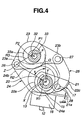
- FIG. 4 is a view similar to FIG. 2, showing minimum lift control of the lift-amount varying mechanism
- FIG. 5 is a view similar to FIG. 4, showing the process from maximum lift control to minimum lift control of the lift-amount varying mechanism
- FIG. 6 is a view similar to FIG. 5, showing maximum lift control of the lift-amount varying mechanism
- FIG. 7 is a graphical representation showing the characteristics of valve lift vs. crank angle
- FIG. 8 is a view similar to FIG. 7, showing the characteristics of lift amount vs. lift phase
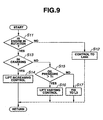
- FIG. 9 is a flowchart showing operation of the first embodiment
- FIG. 10 is a view similar to FIG. 9, showing operation of the first embodiment
- FIG. 11 is a view similar to FIG. 10, showing operation of the first embodiment
- FIG. 12 is a view similar to FIG. 11, showing operation of the first embodiment
- FIG. 13 is a view similar to FIG. 12, showing operation of the first embodiment
- FIG. 14 is a view similar to FIG. 13, showing operation of the first embodiment
- FIG. 15 is a view similar to FIG. 14, showing operation of the first embodiment
- FIG. 16 is a view similar to FIG. 15, showing operation of the first embodiment
- FIG. 17 is a view similar to FIG. 6, taken along the line XVII-XVII, showing a second embodiment of the present invention
- FIG. 18 is a view similar to FIG. 1, showing the VVA apparatus
- FIG. 19 is a view similar to FIG. 8, showing the characteristics of valve lift vs. crank angle
- FIG. 20 is a view similar to FIG. 16, showing operation of the second embodiment
- FIG. 21 is a view similar to FIG. 20, showing operation of the second embodiment
- FIG. 22 is a fragmentary side view showing a third embodiment of the present invention.
- FIG. 23A is a fragmentary front view showing a bracket of a mechanical-switch mechanism
- FIGS. 23B-23D are front views showing a mechanical-switch ring, a torsion coil spring, and a plate, respectively;
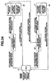
- FIG. 24 is a block diagram showing control in the third embodiment
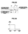
- FIG. 25 is a diagram showing a drive circuit for the lift-amount varying mechanism
- FIG. 26 is a view similar to FIG. 19, showing the on-off switching characteristics of the mechanical-switch mechanism
- FIG. 27 is a view similar to FIG. 26, showing the movable areas of the lift-amount varying mechanism and the lift-phase varying mechanism;
- FIG. 28 is a view similar to FIG. 22, showing a fourth embodiment of the present invention.
- FIGS. 29A-29B are views similar to FIG. 28, showing operation of the mechanical-switch mechanism at maximum lag-angle control and maximum advanced-angle control, respectively;
- FIG. 30 is a view similar to FIG. 24, showing control in the fourth embodiment
- FIG. 31 is a view similar to FIG. 24, showing a drive circuit for the lift-amount varying mechanism
- FIG. 32 is a view similar to FIG. 27, showing the on-off switching characteristics of the mechanical-switch mechanism
- FIG. 33 is a view similar to FIG. 32, showing the movable areas of the lift-amount varying mechanism and the lift-phase varying mechanism;
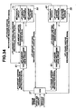
- FIG. 34 is a view similar to FIG. 30, showing a fifth embodiment of the present invention.
- FIG. 35 is a view similar to FIG. 31, showing a drive circuit for the lift-amount varying mechanism
- FIG. 36 is a view similar to FIG. 33, showing the movable areas of the lift-amount varying mechanism and the lift-phase varying mechanism;
- FIG. 37 is a view similar to FIG. 34, showing a sixth embodiment of the present invention.
- FIG. 38 is a view similar to FIG. 35, showing a drive circuit for the lift-amount varying mechanism.
- FIG. 39 is a view similar to FIG. 36, showing the movable areas of the lift-amount varying mechanism and the lift-phase varying mechanism.
- the VVA apparatus is applied to the intake side, and comprises two intake valves 12, 12 per cylinder slidably mounted to a cylinder head 11 through a valve guide, not shown, a lift-amount (first) varying mechanism 1 for varying the lift amount of intake valves 12, 12 in accordance with the engine operating conditions, and a lift-phase (second) varying mechanism 2 for varying the lift phase of intake valves 12, 12 in accordance with the engine operating conditions.
- first first
- second lift-phase
- lift-amount varying mechanism 1 comprises a hollow driving shaft 13 rotatably supported by a bearing 14 in an upper portion of cylinder head 11, two crank cams or eccentric rotary cams 15, 15 fixed to driving shaft 13 through press fitting or the like, two valve operating (VO) cams 17, 17 swingably supported on driving shaft 13 and coming in slide contact with flat top faces 16a, 16a of valve lifters 16, 16 disposed at the upper ends of intake valves 12, 12, two transmission mechanisms 18, 18 each interposed between crank cam 15 and VO cam 17 for transmitting torque of crank cam 15 to VO cam 17 as a rocking force, and a control mechanism 19 for variably controlling the operating position of transmission mechanisms 18, 18.
- VO valve operating
- Driving shaft 13 extends in the engine longitudinal direction, and has one end with a timing sprocket 40 of lift-phase varying mechanism 2 as will be described later, a timing chain wound thereon, etc., not shown, through which driving shaft 13 receives torque from an engine crankshaft.
- bearing 14 comprises a main bracket 14a arranged at the upper end of cylinder head 11 for supporting an upper portion of driving shaft 13, and an auxiliary bracket 14b arranged at the upper end of main bracket 14a for rotatably supporting a control shaft 32 as will be described later.
- Brackets 14a, 14b are fastened together from above by a pair of bolts 14c, 14c.
- crank cam 15 is formed roughly like a ring, and comprises a main body 15a and a cylindrical portion 15b integrated with an outer end face of main body 15a.
- a though hole 15c is axially formed through crank cam 15 to receive driving shaft 13.
- An axis X of cam main body 15a is radially offset with respect to an axis Y of driving shaft 13 by a predetermined amount.
- Crank cams 15, 15 are press fitted via respective through holes 15c to driving shaft 13 at outer sides where no interference occurs with valve lifters 16, 16.
- cam main bodies 15a, 15a have outer peripheral surfaces 15d, 15d of the same cam profile.
- VO cam 17 has a roughly U-shaped profile, and includes one end or circular base end 20 engaged with driving shaft 113 and another end or cam nose 21 formed with a pin hole 21a.
- a lower side of VO cam 17 is formed with a cam face 22 including a base-circle face 22a located at base end 20, a ramp face 22b circularly extending from base-circle face 22a to cam nose 21, and a lift face 22c located at the tip of ramp face 22b.
- Base-circle face 22a, ramp face 22b, and lift face 22c come in contact with given points of top face 16a of valve lifter 16 in accordance with the rocking position of VO cam 17.
- transmission mechanism 18 comprises a rocker arm 23 disposed above driving shaft 13, a crank arm 24 for linking one end or first arm 23a of rocker arm 23 with crank cam 15, and a link rod or member 25 for linking another end or second arm 23b of rocker arm 23 with VO cam 17.
- rocker arm 23 is formed roughly like a crank as viewed in plan, and includes a cylindrical base 23c located in the center and rotatably supported by a control cam 33 as will be described later.
- a pin hole 23d for a pin 26 allowing relatively rotatable coupling with crank arm 24 is formed through first arm 23a protruding from the outer end of base 23c, whereas a pin hole 23e for a pin 27 allowing relatively rotatable coupling with one end 25a of link rod 25 is formed through second arm 23b protruding from the inner end of base 23c.
- crank arm 24 includes a relatively large-diameter annular base 24a and an extension 24b arranged in a predetermined position of the outer peripheral surface of base 24a.
- An engagement hole 24c is formed in the center of base 24a for rotatably receiving the outer peripheral surface of main body 15a of crank cam 15, whereas a pin hole 24d is formed through extension 24b for rotatably receiving pin 26.
- link rod 25 is formed roughly like letter L having a predetermined length, and has first and second ends 25a, 25b formed with pin holes 25c, 25d.
- Rotatably arranged through pin holes 25c, 25d are ends of pins 27, 28 which are also arranged through pin hole 23e of second arm 23b of rocker arm 23 and pin hole 21a of cam nose 21 of VO cam 17, respectively.
- Link rod 25 serves to restrict the maximum rocking range of VO cam 17 within the rocking range of rocker arm 23.
- Pins 26, 27, 28 Arranged at respective one ends of pins 26, 27, 28 are snap rings for restricting axial movement of crank arm 24 and link rod 25.
- Control mechanism 19 comprises control shaft 32 arranged in the engine longitudinal direction, control cam 33 fixed at the outer periphery of control shaft 32 to form a rocking fulcrum of rocker arm 23, and an electric motor or actuator 34 for controlling the rotational position of control shaft 32.
- control shaft 32 is disposed parallel to driving shaft 13, and is rotatably supported between a bearing groove formed in the upper end of main bracket 14a and auxiliary bracket 14b as described above.
- Control cam 33 is of the cylindrical shape, an axis P1 of which is offset with respect to an axis P2 of control shaft 32 by a predetermined amount ⁇ as shown in FIG. 2.
- Motor 34 transmits torque to control shaft 32 through mesh of a first spur gear 35 formed at an end of a driving shaft 34a of motor 34 with a second spur gear 36 formed at a rear end of control shaft 32.
- Motor 34 is driven in accordance with a control signal of an electronic control unit (ECU) 37 for determining the engine operating conditions.
- ECU electronice control unit
- lift-phase varying mechanism 2 comprises a timing sprocket 40 arranged at the tip of driving shaft 13 for receiving torque of the engine crankshaft by means of a timing chain, not shown, a sleeve 42 fixed axially at the tip of driving shaft 13 by a bolt 41, a cylindrical gear 43 interposed between timing sprocket 40 and sleeve 42, and a hydraulic circuit or drive mechanism 44 for driving cylindrical gear 43 in the longitudinal axial direction of driving shaft 13.
- Timing sprocket 40 comprises a cylindrical main body 40a, a sprocket 40b fixed at the rear end of main body 40a by bolts 45 and having a chain wound thereon, and a cover 40c for closing a front-end opening of main body 40a.
- the inner peripheral surface of main body 40a is formed with helical inner teeth 46.
- Sleeve 42 has a rear end formed with an engaging groove with which the tip of driving shaft 13 is engaged, and a front end formed with a holding groove in which a coil spring 47 is provided to bias timing sprocket 40 forward.
- the outer peripheral surface of sleeve 42 is formed with helical outer teeth 48.
- Cylindrical gear 43 includes two portions obtained by dividing from the axially right-angle direction, wherein the two gear components are biased by means of a pin and spring to approach each other. Cylindrical gear 43 has inner and outer peripheral surfaces formed with helical inner and outer teeth meshed with inner teeth 46 and outer teeth 48, respectively. Cylindrical gear 43 is moved in the longitudinal axial direction and in slide contact with the teeth by means of the hydraulic pressure provided relatively to first and second hydraulic chambers 49, 50 disposed before and after gear 43. In the maximally forward moving position of abutting on front cover 40c, cylindrical gear 43 controls intake valve 12 in the maximum lag-angle position, whereas in the maximally rearward moving position, it controls intake valve 12 in the maximum advance-angle position. When failing to receive the hydraulic pressure within first hydraulic chamber 49, cylindrical gear 43 is biased in the maximally forward moving position by a return spring 51 arranged in second hydraulic chamber 50.
- hydraulic circuit 44 comprises a main gallery 53 connected to the downstream side of an oil pump 52 communicating with an oil pan, not shown, first and second hydraulic passages 54, 55 branched from the downstream side of main gallery 53 to communicate with hydraulic chambers 49, 50, a solenoid-type passage selector valve 56 arranged in the branch position, and a drain passage 57 connected to passage selector valve 56.
- Passage selector valve 56 is driven in accordance with a control signal derived from ECU 37 which also controls motor 34 of lift-amount varying mechanism 1.
- Lift-amount varying mechanism 1 comprises a lift-amount detecting (first) sensor or means 58 for detecting an actual rotational position of control shaft 32, and an auxiliary lift-amount detecting (first auxiliary) sensor 60 for detecting the lift amount in an auxiliary way.
- lift-phase varying mechanism 2 comprises a lift-phase detecting (second) sensor or means 59 for detecting a relative rotational position between driving shaft 13 and timing sprocket 40, and an auxiliary lift-phase detecting (second auxiliary) sensor 61 for detecting the lift phase in an auxiliary way.
- ECU 37 determines actual engine operating conditions through operation or the like in accordance with detection signals derived from various sensors, i.e. an engine-speed signal derived from a crank-angle sensor, an intake-air-flow or load signal derived from an airflow meter, an oil-temperature signal derived from an engine-oil temperature sensor, etc.
- ECU 37 provides control signals to motor 34 and passage selector valve 56 in accordance with detection signals derived from lift-amount detecting sensor 58 and lift-phase detecting sensor 59.
- ECU 37 determines a target lift characteristic of intake valve 12, i.e. a target rotational position of control shaft 32, in accordance with information signals indicative of engine speed, load, oil temperature, elapsed time after engine start, etc., based on which motor 34 is driven to rotate control cam 33 up to a predetermined rotation-angle position through control shaft 32.
- An actual rotational position of control shaft 32 is monitored through lift-amount detecting sensor 58 to rotate control shaft 32 to a target phase by means of feedback control.
- control shaft 32 is rotated in one direction through motor 34 in accordance with a control signal derived from ECU 37, so that control cam 33 has axis P1 held in the rotational position left above axis P2 of control shaft 32, and a thick portion 33a rotated upward with respect to driving shaft 13.
- rocker arm 23 is moved in its entirety upward with respect to driving shaft 13, so that VO cam 17 is forcibly pulled upward through link rod 25 to rotate counterclockwise. Therefore, referring to FIGS.
- crank cam 15 when crank cam 15 is rotated to press first arm 23a of rocker arm 23 upward through crank arm 24, the corresponding lift amount is transmitted to VO cam 17 and valve lifter 16 through link rod 25, which has a small value L. This enhances gas flow and thus combustion, resulting in improved fuel consumption and stabilized engine rotation.
- valve lift amount is set to zero or a minimum value Lmin close to zero as shown in FIG. 7, achieving excellent build-up of engine rotation as will be described later.
- control shaft 32 is rotated in another direction by motor 34 in accordance with a control signal derived from ECU 37 to rotate control cam 33 to the position shown in FIGS. 2 and 6 for downward rotation of thick portion 33a.
- rocker arm 23 is moved in its entirety to the driving shaft 13 or downward to have second arm 23b pressing VO cam 17 downward through rank arm 25, rotating VO cam 17 in its entirety to the position shown in FIGS. 2 and 6 or clockwise by a predetermined amount. Therefore, when crank cam 15 is rotated to press first arm 23a of rocker arm 23 upward through crank arm 24, the corresponding lift amount is transmitted to VO cam 17 and valve lifter 16 through link rod 25, which has a maximum value Lmax as shown in FIG. 6.
- FIG. 7 shows Lmin as a minimum value close to zero, Lmin can be zero by further rotating control shaft 32 in one direction.
- ECU 37 determines a target advance-angle amount of intake valve 12 in accordance with information signals derived from various sensors in the same way as described above, based on which passage selector valve 56 carries out communication between first hydraulic passage 54 and main gallery 53 during a predetermined duration and communication between second hydraulic passage 54 and drain passage 57 during a predetermined duration. With this, a relative rotational position between driving shaft 13 and timing sprocket 40 is changed through cylindrical gear 43, achieving control to the advance-angle side. An actual relative rotational position of driving shaft 13 is monitored in advance through lift-phase detecting sensor 59 to rotate driving shaft 13 to a target relative rotational position or target advance-angle amount by means of feedback control.
- passage selector valve 56 supplies the hydraulic pressure to second hydraulic chamber 50 only, and not to first hydraulic chamber 49. Therefore, cylindrical gear 43 is held in the most forward position by the force of return spring 51 as shown in FIG. 1, having driving shaft 13 held in the rotational position of maximum lag angle. Then, when the oil temperature exceeds predetermined temperature To, passage selector valve 56 is driven based on a control signal derived from ECU 37 and in accordance with the engine operating conditions to continuously change a duration for carrying out communication between first hydraulic passage 54 and main gallery 53 and communication between second hydraulic passage 52 and drain passage 57.
- cylindrical gear 43 is moved from the most forward position to the most rearward position, so that, referring to FIG. 7, the opening/closing timing of intake valve 12 is variably controlled from the maximum lag-angle state indicated by solid line to the maximum advance-angle state indicated by broken line.
- vertical line A shows lift phase in the maximum lag-angle position
- vertical broken line A' shows lift phase in the maximum advance-angle position. Therefore, assuming that the lift amount and lift phase are optionally varied by lift-amount varying mechanism 1 and lift-phase varying mechanism 2, respectively, a possible range of lift amount and lift phase is shown by a portion enclosed by lines A, A' and horizontal lines Lmin, Lmax.
- a portion with oblique line shows an interference area of the component members in the controllable lift-amount and lift-phase range shown in FIG. 7.
- the boundary forms an interference limit line (shown by broken line).
- an interference warning line (shown by solid line) exists on the lag-angle low-lift side. Interference does not occur immediately beyond the warning line, however, in consideration of overshoot so called, the possibility appears to enter the interference producing area.
- Point "a" in FIG. 8 shows a position controlled to roughly minimum lift amount Lmin at engine start, wherein the cranking rpm builds up quickly because of small valve actuation friction.
- lift-phase varying mechanism 2 is roughly at the maximum lag angle. This is to avoid poor combustion which becomes a problem when the engine is cold by bringing the opening timing of intake valve 12 near the bottom dead center (BDC) for enhancement of the effective compression ratio so called. Within the range of change between points "a" and "d" (vertical direction in FIG. 8), interference may not occur because of sufficient distance from the interference limit line.
- step S11 it is determined whether or not the engine is in rotation. If it is determined that the engine is at a standstill, flow proceeds to a step S12 where lift-amount varying mechanism 1 is controlled to minimum lift Lmin close to zero. In step S11, if it is determined that the engine is in rotation, flow proceeds to a step S13 where it is determined whether or not the engine is in cranking.
- step S14 If it is determined that the engine is in cranking, flow proceeds to a step S14 where with an increase in engine speed or cranking rpm, control of increasing the lift up to a value L3 on solid line in FIG. 7 is carried out by means of lift-amount varying mechanism 1.
- step S13 If it is determined that the engine is not in cranking, flow proceeds to a step S15 where it is determined whether or not the actual oil temperature is higher than predetermined temperature T1 by means of the oil temperature sensor. If it is determined that the oil temperature is higher than T1, flow proceeds to a step S16 where lift varying control is carried out with lift-amount varying mechanism 1 in accordance with the engine operating conditions. In step S15, if it is determined that the oil temperature is lower than or equal to T1, flow proceeds to a step S17 where lift control fixed to L3 is carried out with lift-amount varying mechanism 1. Then, one flow is completed.
- the lift is controlled to the minimum lift in step S12, providing small friction of the valve actuation system, resulting in quick build-up of engine rotation.
- step S14 lift increasing control in step S14 improves the gas exchange efficiency of air-fuel mixture, achieving quick build-up of engine torque, resulting in greatly improved engine startability in combination with the above quick build-up of engine rotation.
- step S17 the lift is fixed to relatively low lift L3 in step S17, which increases the speed of air-fuel mixture from intake valve 12 to generate strong gas flow in the cylinder, resulting in improved combustion at start in cold engine and in fuel-consumption performance and exhaust emission performance.
- point "g" shows a control position for a partial load, wherein the lift phase is advanced to near the interference warning line so as to improve the fuel consumption as much as possible, namely, the valve overlap so called is increased to the limit to increase residual gas for reduction in pumping loss.
- intake valve 12 has sufficiently quick closing timing, achieving a full reduction in pumping loss, resulting in further improved fuel consumption.
- the lift phase is moved to the lag-angle side by a predetermined amount ⁇ s to come at the lift-phase correction target position of point "g2", preventing shifting to the interference limit line, thus avoiding interference due to overshoot.
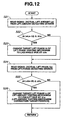
- FIG. 10 shows a flowchart of the above control. Since an output signal derived from lift-amount detecting sensor 58 and an actual lift amount are in a one-to-one correspondence, actual lift amount La is determined based on the output signal.
- actual lift amount La is read from lift-amount detecting sensor 58.
- a step S2 it is determined whether or not a difference ⁇ L between actual lift amount La and basic target value Lt is equal to or larger than a predetermined amount ⁇ Lo. If it is determined that ⁇ L ⁇ ⁇ Lo, it is determined that the lift phase may not reach the interference limit line beyond the interference warning line, and flow returns to START.
- step S3 the lift-phase target value is moved to the lift-phase correction target value (point "g2") on the lag-angle side by a predetermined amount ⁇ s by means of lift-phase varying mechanism 2. This can prevent the lift phase from reaching the interference limit line, thus avoiding interference.
- two-dot chain line passing through point "g2" forms a correction target line, which can be given on a map, etc.
- a detection signal or actual lift phase ⁇ a which is in a one-to-one relationship with the twist angle of driving shaft 13 is read from lift-phase detecting sensor 59.
- a step S12A it is determined whether or not a difference ⁇ between actual lift phase ⁇ a and lift-phase target value ⁇ t is equal to or larger than a predetermined value ⁇ o. If it is determined that ⁇ ⁇ ⁇ o, flow returns to START because of no possible interference. On the other hand, if it is determined that ⁇ ⁇ ⁇ o, i.e.
- step S13A target lift amount Lt is changed to the lower lift side by correction target lift amount ⁇ Ls, i.e. to point "g4", by means of lift-amount varying mechanism 1.
- lift-amount control can prevent interference between piston and intake valve 12, etc. due to overshoot of the lift phase.
- step S21 an output signal or actual lift amount La is read from lift-amount detecting sensor 58.
- step S22 it is determined whether or not difference ⁇ L between actual lift amount La and basic target value Lt is equal to or larger than predetermined value ⁇ Lo.
- step S24 If it is determined that ⁇ L ⁇ ⁇ Lo, flow proceeds to a step S24, whereas if it is determined that ⁇ L ⁇ ⁇ Lo, flow proceeds to a step S23 because of possible interference, where target lift phase ⁇ t of lift-phase varying mechanism 2 is changed to the lag-angle side by ⁇ s, i.e. to the correction target position of lift-phase varying mechanism 2.
- step S24 a detection signal or actual lift phase ⁇ a is read from lift-phase detecting sensor 59.
- step S25 it is determined whether or not difference ⁇ between actual lift phase ⁇ a and lift phase target value ⁇ t is equal to or larger than predetermined value ⁇ o. If it is determined that ⁇ ⁇ ⁇ o, flow returns to START because of no possible interference. On the other hand, if it is determined that ⁇ ⁇ ⁇ o, i.e. when the lift phase exceeds the interference warning line, flow proceeds to a step S26 where target lift amount Lt is changed to the lower lift side by correction target lift amount ⁇ Ls, i.e. to point "g4", by means of lift-amount varying mechanism 1. Then, one flow is completed.
- lift-phase correction target value ⁇ t is further moved to the lag-angle side by ⁇ s. Then, actual lift phase ⁇ a is read. If ⁇ a is shifted to the advance-angle side by ⁇ o or more with respect to new ⁇ t, Lt is controlled to a lift lower by ⁇ Ls. Interference is avoided by repeated execution of such flow.
- interference avoiding control effectively functions in an operation area having lift characteristic close to the interference warning line such as partial load area.
- control is not required per se in an operation area having lift characteristic away from the interference warning line. And if this control is carried out, the engine performance will be deteriorated. Therefore, it is preferable not to carry out interference avoiding control in the operation area having lift characteristic away from the interference warning line, which leads to simplified control and favorable engine performance.
- one-dot chain line connecting point “f” and point “e” shows a change line at full load.
- point “e” is sufficiently away from the interference warning line and correction target line, where interference hardly occurs per se.
- the change line is moved to point "e"' due to overshoot of the lift amount, it is situated on the lift-phase lag-angle side with respect to point "e2" on the correction target line with the same lift amount.
- control on point "e”' is situated on the safe side with respect to control on "e2" against interference, and more effective in output torque, maintaining control on point “e”', i.e. carrying out control without changing ⁇ t to the correction target position, obtaining simplified control.
- step S31 actual lift amount La is read from lift-amount detecting sensor 58.
- step S32 it is determined whether or not difference ⁇ L between actual lift amount La and basic target value Lt is equal to or larger than a predetermined lift amount ⁇ Lo.
- step S33 it is determined whether or not actual lift-phase target value ⁇ t is situated on the advance-angle side with respect to the lift-phase correction target value (point e2). If it is determined that ⁇ t is not situated on the advance-angle side, flow proceeds to a step S34 where interference avoiding control, i.e. control of replacing ⁇ t with the correction target position, is carried out.
- control is carried out without changing the target value ⁇ t, i.e. with the actual target position maintained without using the correction target position. This can avoid interference without interference avoiding control.
- a correction target line on which interference can be avoided is previously determined on a map, etc.
- a detection signal of actual lift phase ⁇ a is read from lift-phase detecting sensor 59.
- a step S42 it is determined whether or not difference ⁇ between actual lift phase ⁇ a and basic target value ⁇ t is equal to or larger than predetermined lift phase ⁇ . If it is determined that ⁇ ⁇ ⁇ o, flow returns to START, whereas if it is determined that ⁇ ⁇ ⁇ o, flow proceeds to a step S43 where it is determined whether or not actual lift-amount target value Lt is larger than the correction target lift of lift-amount varying mechanism 1.
- target lift amount Lt of the lift-amount varying mechanism 1 is not changed.
- lift-amount detecting sensor 58 and lift-phase detecting sensor 59 are not in failure.
- ECU 37 will not able to correctly recognize actual lift amount La and actual lift phase ⁇ a, leading to frequent occurrence of an interference problem.
- auxiliary lift-amount detecting sensor 60 and auxiliary lift-phase detecting sensor 61 are arranged, in addition to detecting sensors 58, 59, auxiliary lift-amount detecting sensor 60 and auxiliary lift-phase detecting sensor 61 to allow prompt detection of a failure of detecting sensors 58, 59 through comparison of the respective corresponding detection signals.
- a detection signal or actual lift amount La is read from lift-amount detecting sensor 58.
- a detection signal or actual lift amount La' is read from auxiliary lift-amount detecting sensor 60.
- step S53 it is determined whether or not a difference between actual lift amounts La and La' is equal to or smaller than a predetermined value ⁇ L.
- step S54 it is determined whether or not difference ⁇ L between actual lift amount La and actual lift-amount target value Lt is equal to or larger than predetermined value ⁇ Lo. If it is determined that ⁇ L ⁇ ⁇ Lo, flow returns to START, whereas if it is determined that ⁇ L ⁇ ⁇ Lo, flow proceeds to a step S55 where target lift phase ⁇ t of lift-phase varying mechanism 2 is changed to the lag-angle side by ⁇ s to carry out interference avoiding control.
- step S53 if it is determined that
- the lift phase is continuously controlled within the range A, deterioration of the operation performance can be restrained. Moreover, if the lift phase is fixed to the maximum lag angle within the range A, interference can be more securely prevented with control simplified. Further, if the lift phase is fixed approximately in the middle within the range A, deterioration of the operation performance can be restrained to some extent while securely preventing interference with control simplified.
- step S61 a detection signal or actual lift phase ⁇ a is read from lift-phase detecting sensor 59, and in a step S62, a detection signal or actual lift phase ⁇ a' is read from auxiliary lift-phase detecting sensor 61.
- step S63 it is determined whether or not a difference between actual lift phases ⁇ a and ⁇ a' is equal to or smaller than predetermined value ⁇ .
- step S64 it is determined whether or not difference ⁇ between actual lift phase ⁇ a and target lift phase ⁇ t is equal to or larger than predetermined value ⁇ o. If it is determined that ⁇ ⁇ ⁇ o, flow returns to START, whereas if it is determined that ⁇ ⁇ ⁇ o, flow proceeds to a step S65 where target lift phase Lt of lift-amount varying mechanism 1 is changed to the low lift side by ⁇ Ls to carry out interference avoiding control.
- step S63 if it is determined that
- the lift amount is continuously controlled within the range B, deterioration of the operation performance such as decrease in output torque can be restrained. Moreover, if the lift amount is fixed to minimum lift Lmin within the range B, interference can be more securely prevented with control simplified. Further, if the lift amount is fixed approximately in the middle within the range B, deterioration of the operation performance can be restrained to some extent while securely preventing interference with control simplified.
- ECU 37 determines a failure of lift-phase detecting sensor 59 after it occurs. Since the actual position detections by lift-phase detecting sensor 59 and by auxiliary lift-phase detecting sensor 61 are sampled in very short time intervals of about several microseconds, ECU 37 can substantially immediately recognize failure occurrence, thus preventing occurrence of interference due to time lag in recognizing the failure. In addition to interference prevention, knocking due to unmatched ignition timing, emission increase due to unmatched fuel injection quantity, etc. can be immediately prevented.
- rock-timing sensor 62 and auxiliary rock-timing sensor 63 are arranged to detect through protrusions 64, 65 the timing when VO cams 17, 17 of lift-amount varying mechanism 1 come to a predetermined rocking position or predetermined lift position.
- Rock-timing sensors 62, 63 are of the non-contact type using Hall element, etc.
- protrusions 64, 65 having roughly the same shape are provided on the top of cam nose 21 of VO cams 17, and rock-timing sensor 62 and auxiliary rock-timing sensor 63 are mounted to cylinder head 11 in the position through which protrusions 64, 65 pass during rocking.
- the position of rock-timing sensors 62, 63 come into agreement with the position of protrusions 64, 65. That is, the lift-start point and lift-end point of intake valves 12, 12 form detection timings.
- the detected rocking timings occur once on the lift up side (up rocking timing) and once on the lift down side (down rocking timing), and have phases ⁇ 1, ⁇ 2, ⁇ 1', ⁇ 2' shifted with respect to the reference crank-angle phase as shown in FIG. 19.
- the lift amount and lift phase can be obtained based on phases ⁇ 1, ⁇ 2, ⁇ 1', ⁇ 2'.
- This operation is explained in connection with rock-timing sensor 63.
- the difference ⁇ 2 - ⁇ 1 which indicates a valve opening period, is in a one-to-one correspondence with actual lift amount La, which allows detection of actual lift amount La (L1 in FIG. 19). If ⁇ 1 and ⁇ 2 are known, actual lift phase ⁇ a can be detected by the same rock-timing sensor 63 because ⁇ a is located roughly in the intermediate position between ⁇ 1 and ⁇ 2.
- auxiliary rock-timing sensor 64 since VO cams 17, 17 swing with the same characteristic as that of rock-timing sensor 63, and intake valves 12, 12 lift also with the same characteristic, actual lift amount La' and actual lift phase ⁇ a' detected by auxiliary rock-timing sensor 64 ordinarily correspond to actual lift amount La and actual lift phase ⁇ a detected by rock-timing sensor 63. If they do not correspond to each other, however, rock-timing sensor 63 may be faulty.
- phase S71 phases ⁇ 1, ⁇ 2 are detected by rock-timing sensor 63, and in a step S72, actual lift amount La and actual lift phase ⁇ a are determined based on ⁇ 1, ⁇ 2 through operation.
- phases ⁇ 1', ⁇ 2' are detected by auxiliary rock-timing sensor 64, and in a step S74, actual lift amount La' and actual lift phase ⁇ a' are determined based on ⁇ 1', ⁇ 2' through operation.
- step S75 it is determined whether or not a difference between actual lift amounts La and La' is equal to or smaller than predetermined value ⁇ L.
- step S76 it is determined whether or not a difference between actual lift phases ⁇ a and ⁇ a' is equal to or smaller than predetermined value ⁇ . If it is determined that
- steps S75, S76 if it is determined that the differences are larger than respective predetermined values ⁇ L, ⁇ , the possibility of failure is high, and thus flow proceeds to a step S78 where open control is carried out toward the minimum lift by lift-amount varying mechanism 1 and toward the maximum lag angle by lift-phase varying mechanism 2. This allows secure avoiding of interference between the piston and intake valve 12, etc.
- open control is carried out to the safe side by both changing mechanisms 1, 2 is that not only the La recognition, but also the ⁇ a recognition may be wrong when rock-timing sensor 63 fails.
- failure detection, etc. can be carried out with only two sensors 63, 64, achieving simplified system configuration, resulting in improved manufacturing and assembling efficiency and reduced manufacturing cost.
- rock-timing sensor 63 and auxiliary rock-timing sensor 64 are provided to the same cylinder.
- they may be provided to separate and distinct cylinders.
- auxiliary rock-timing sensor 64 not only for failure detection, but also for ordinary feedback control provides improved control accuracy in the same way as to shorten sampling interval. Moreover, even under such circumstances that auxiliary rock-timing sensor 64 is used for control, a failure of rock-timing sensor 63 can be detected from comparison between actual lift amount La and actual lift phase ⁇ a detected by rock-timing sensor 63 through the same control as that in FIG. 20.
- steps S81 and S82 actual lift amount La and actual lift phase ⁇ a of No. 1 (#1) cylinder are determined based on phases ⁇ 1, ⁇ 2 detected by rock-timing sensor 63 provided to #1 cylinder.
- steps S83 and S84 actual lift amount La' and actual lift phase ⁇ a' of #4 cylinder are determined based on phases ⁇ 1', ⁇ 2' detected by auxiliary rock-timing sensor 64 provided to #4 cylinder. Since the ignition sequence is #1 - #3 - #4 - #2, detection is carried out at an equal interval.
- steps S85 and S86 differences between La and La' and between ⁇ a and ⁇ a' are checked.
- step S87 feedback control of lift-amount varying mechanism 1 is carried out based on actual lift amounts La, La', and ordinary feedback control of lift-phase varying mechanism 2 is carried out based on actual lift phases ⁇ a, ⁇ a'.
- steps S85, S86 if it is determined that the differences are equal to or larger than predetermined values ⁇ L, ⁇ , rock-timing sensor 63 may be faulty in the same way as in FIG. 20, and thus flow proceeds to a step S88 where lift-amount varying mechanism 1 and lift-phase varying mechanism 2 are open controlled toward the minimum lift and the maximum lag angle, respectively.
- sampling of detection on actual lift amounts includes La' of #4 cylinder in addition to La of #1 cylinder, which is an equivalence of substantially 1/2 reduction in sampling interval, resulting in improved accuracy of feedback control of lift-amount varying mechanism 1.
- sampling of detection on actual lift phases includes ⁇ a' of #4 cylinder in addition to ⁇ a of #1 cylinder, which is an equivalence of substantially 1/2 reduction in sampling interval, resulting in improved accuracy of feedback control of lift-phase varying mechanism 2.
- interference avoiding control is explained with regard to the case that both lift-amount varying mechanism 1 and lift-phase varying mechanism 2 are provided to intake valve 12. The same interference avoiding control is applicable when they are provided to the exhaust valve 12. In the latter case, a unfavorable direction for interference approaching TDC is the lag-angle side.
- FIGS. 22-27 there is shown a third embodiment of the present invention which is substantially same in structure except that lift-amount varying mechanism 1 and lift-phase varying mechanism 2 are provided with mechanical-switch mechanisms, respectively.
- lift-amount varying mechanism 1 is provided with a first mechanical-switch mechanism 70 which comprises a bracket 71 for receiving and rotatably supporting an end of control shaft 32, a mechanical-switch ring 73 rotatably engaged with the outer peripheral surface of a tubular portion 72 integrally formed with the front end face of bracket 71 at the edge of a through hole 71a, a ring-rotation pin 74 radially protruding from the periphery of the end of control shaft 32 and engaged with a lever 73a axially protruding from the outer peripheral edge of ring 73 for rotation thereof, a torsion coil spring 76 wound around tubular portion 72 and having one end 76a engaged with an engagement portion 75 on the front face of bracket 71 and another end 76b engaged with lever 73a, and an annular plate 77 interposed between a flange 32a provided on the periphery of the end of control shaft 32 and torsion
- Bracket 71 is provided on its front end face with a push switch 78 on which lever 73a abuts, and tubular portion 72 is provided on its front end with three stopper pins 79 for stopping plate 77.
- Circuit 80 which receives on/off signals from push switch 78 and provides them to a drive circuit 82 of lift-phase varying mechanism 2 as shown in FIGS. 24-25.
- Circuit 80 comprises a relay switch 80a of the normally closed contact type, a resistor 80b, etc.
- push switch 78 When push switch 78 is turned off, the contact of relay switch 80a is turned on to provide power voltage to a switch-state detecting part for recognition of the on state, whereas when push switch 78 is turned on, the contact of relay switch 80a is turned off to provide the ground (GND) to the switch-state detecting part for recognition of the off state.
- GND ground
- FIG. 24 is a block diagram showing control of ECU 37 for lift-amount varying mechanism 1 and lift-phase varying mechanism 2.
- ECU 37 for determining the engine operating conditions based on information signals derived from the sensors outputs control signals to a lift-amount varying mechanism drive circuit 81 and a lift-phase varying mechanism drive circuit 82, thus outputting drive signals to the actuators of varying mechanisms 1, 2.
- ECU 37 outputs the control signals based on feedback signals derived from lift-amount detecting sensor 58 and lift-phase detecting sensor 59. Signals derived from mechanical-switch mechanism 70 are provided to lift-phase varying mechanism drive circuit 82.
- the signals derived from mechanical-switch circuit 80 of mechanical-switch mechanism 70 are inputted, together with drive instruction signals for lift-phase varying mechanism 2, to an AND circuit 83a which constitutes a logic circuit 83. Then, via a drive-circuit part 84, they are outputted as actuator drive signals for lift-phase varying mechanism 2.
- control shaft 32 rotates in the direction of arrow A in FIG. 22 in accordance with the engine operating conditions, i.e. in the case of small lift control
- push switch 78 is turned off, so that mechanical-switch circuit 80 outputs a on signal to logic circuit 83.
- a on signal is outputted to logic circuit 83, allowing sufficient control to the advance-angle side without restricting control of lift-phase varying mechanism 2.
- control shaft 32 rotates in the direction of arrow B in FIG. 22 to have the rotation amount greater than a predetermined value or point A in FIG. 26, thereby turning on push switch 78, mechanical-switch circuit 80 outputs a off signal to logic circuit 83.
- a on signal is outputted to AND circuit 83a of logic circuit 83, so that at the time when mechanical-switch circuit 80 outputs a off signal, control to the advance-angle side by lift-phase varying mechanism 2 is restricted.
- the drive or movable areas of varying mechanisms 1, 2 are securely restricted roughly at point A as a boundary where SW1 becomes turned off. This leads to possible avoiding of interference between piston and intake valve 12 or intake valve 12 and exhaust valve.
- FIG. 28 there is shown a fourth embodiment of the present invention wherein mechanical-switch mechanism 90 is provided only to lift-phase varying mechanism 2 with no mechanical-switch mechanism 70 provided to lift-amount varying mechanism 1.
- Mechanical-switch mechanism 90 comprises a roughly cylindrical housing 91 fixed to the front face of front cover 40c of timing sprocket 40, a disk-like movable contact 92 axially slidably provided in housing 91, two stationary contacts 93a, 93b fixed to the right inner peripheral surface of housing 91 as viewed in FIG.
- cylindrical gear 43 occupies the maximum lag-angle position when it is at a forward position on the side of front cover 40c, and occupies the maximum advance-angle position when it is at a backward position away from front cover 40c.
- Movable contact 92 is biased forward, i.e. in the direction where switch pin 94 abuts on cylindrical gear 43, by a coil spring 98.
- Switch pin 94 has a flange-like stopper 94a on the side of movable contact 92.
- Mechanical-switch circuit 97 has the same configuration as that of mechanical-switch circuit 80 of lift-amount varying mechanism 1, comprising a relay switch 97a of the normally closed contact type, a resistor 97b, etc., wherein the switch-state detecting part is connected to the drive circuit of lift-amount varying mechanism 1.
- movable contact 92 is moved backward against the force of coil spring 98 to separate from stationary contacts 93a, 93b for the off state, the contact of relay switch 97a is turned on to provide power-supply voltage to the switch-state detecting part for recognition of the on state.
- FIG. 30 is a block diagram showing control of ECU 37 for lift amount mechanism 1 and lift-phase varying mechanism 2, which is basically the same as that in FIG. 24 except that signals derived from mechanical-switch mechanism 90 are provided to lift-amount varying mechanism drive circuit 81.
- signals derived from mechanical-switch circuit 97 of mechanical-switch mechanism 90 are inputted, together with a drive instruction signal for lift-amount varying mechanism 1, to AND circuit 83a which constitutes logic circuit 83. Then, via drive circuit part 84, they are outputted as actuator driving signals for lift-amount varying mechanism 1.
- varying mechanisms 1, 2 are provided with first and second mechanical-switch mechanisms 70, 90, respectively, mechanical-switch signals of which are outputted to drive circuit 81 of lift-amount varying mechanism 1.
- the drive instruction signal for lift-amount varying mechanism 1 is outputted to AND circuit 83a of logic circuit 83, and the mechanical-switch signals are outputted to an OR circuit 83b of logic circuit 83.
- an actuator driving signal for lift-amount varying mechanism 1 is provided.
- two off signals are inputted, i.e. the lift amount and lift phase are greater and more advanced than respective predetermined values, lift control of lift-amount varying mechanism 1 is restricted through drive circuit 84.
- both varying mechanisms 1, 2 can be controlled relatively accurately, resulting in not only achievement of the effect of avoiding interference between piston and intake valve 12, but also provision of relatively large drive or movable areas as shown in FIG. 36.
- FIG. 37 shows a sixth embodiment of the present invention wherein varying mechanisms 1, 2 are provided with first and second mechanical-switch mechanisms 70, 90, but mechanical-switch signals of which are outputted to drive circuit 82 of lift-phase varying mechanism 2.
- the drive instruction signal for lift-phase varying mechanism 2 is inputted to AND circuit 83a of logic circuit 83, and the mechanical-switch signals are inputted to OR circuit 83b of logic circuit 83.
- OR circuit 83b When a on signal of either control shaft 32 or cylindrical gear 43 is inputted to OR circuit 83b, an actuator driving signal for lift-phase varying mechanism 2 is provided.
- two off signals are inputted, i.e. the lift amount and lift phase are greater and more advanced than respective predetermined values, lift control of lift-phase varying mechanism 2 is restricted through drive circuit 84.
- both varying mechanisms 1, 2 can be controlled relatively accurately, resulting in not only the effect of avoiding interference between piston and intake valve 12, but also provision of relatively large drive or movable areas as shown in FIG. 39.
- the present invention can be applied to the exhaust side.
Landscapes
- Engineering & Computer Science (AREA)
- Mechanical Engineering (AREA)
- General Engineering & Computer Science (AREA)
- Output Control And Ontrol Of Special Type Engine (AREA)
- Valve Device For Special Equipments (AREA)
- Electrical Control Of Air Or Fuel Supplied To Internal-Combustion Engine (AREA)
- Combined Controls Of Internal Combustion Engines (AREA)
Applications Claiming Priority (2)
| Application Number | Priority Date | Filing Date | Title |
|---|---|---|---|
| JP2001138206 | 2001-05-09 | ||
| JP2001138206A JP4373028B2 (ja) | 2001-05-09 | 2001-05-09 | 内燃機関の可変動弁装置及びその制御方法 |
Publications (3)
| Publication Number | Publication Date |
|---|---|
| EP1258601A2 EP1258601A2 (en) | 2002-11-20 |
| EP1258601A3 EP1258601A3 (en) | 2003-05-28 |
| EP1258601B1 true EP1258601B1 (en) | 2004-12-15 |
Family
ID=18985180
Family Applications (1)
| Application Number | Title | Priority Date | Filing Date |
|---|---|---|---|
| EP02008857A Expired - Lifetime EP1258601B1 (en) | 2001-05-09 | 2002-04-19 | Variable-valve-actuation apparatus for internal combustion engine |
Country Status (4)
| Country | Link |
|---|---|
| US (1) | US6575128B2 (ja) |
| EP (1) | EP1258601B1 (ja) |
| JP (1) | JP4373028B2 (ja) |
| DE (1) | DE60202239T2 (ja) |
Families Citing this family (53)
| Publication number | Priority date | Publication date | Assignee | Title |
|---|---|---|---|---|
| JP2003027973A (ja) * | 2001-07-12 | 2003-01-29 | Hitachi Unisia Automotive Ltd | 可変動弁機構の制御装置 |
| JP2003129871A (ja) * | 2001-10-23 | 2003-05-08 | Hitachi Unisia Automotive Ltd | 内燃機関の可変バルブ制御装置 |
| US6810844B2 (en) * | 2002-12-10 | 2004-11-02 | Delphi Technologies, Inc. | Method for 3-step variable valve actuation |
| US20040261736A1 (en) * | 2003-04-17 | 2004-12-30 | Babbitt Guy Robert | Methods of controlling a camless engine to prevent interference between valves and pistons |
| JP4228785B2 (ja) * | 2003-06-03 | 2009-02-25 | スズキ株式会社 | エンジンの制御装置 |
| US6994061B2 (en) * | 2003-11-13 | 2006-02-07 | Ford Global Technologies, Llc | Computer readable storage medium for use with engine having variable valve actuator during degradation |
| US6938593B2 (en) * | 2003-11-13 | 2005-09-06 | Ford Global Technologies, Llc | Computer readable storage medium for use with engine having variable valve actuator |
| JP4458414B2 (ja) * | 2004-02-09 | 2010-04-28 | 日立オートモティブシステムズ株式会社 | バルブリフト可変機構の駆動制御装置 |
| JP4396339B2 (ja) * | 2004-03-18 | 2010-01-13 | 日産自動車株式会社 | 内燃機関の吸気弁駆動制御装置 |
| JP4046105B2 (ja) * | 2004-06-11 | 2008-02-13 | トヨタ自動車株式会社 | エンジンの可変動弁機構 |
| JP4440022B2 (ja) | 2004-07-14 | 2010-03-24 | 本田技研工業株式会社 | 可変動弁装置を備える内燃機関の制御装置 |
| JP4792215B2 (ja) * | 2004-09-09 | 2011-10-12 | トヨタ自動車株式会社 | 内燃機関の制御装置 |
| JP4096939B2 (ja) * | 2004-12-06 | 2008-06-04 | 日産自動車株式会社 | 可変動弁機構の制御装置及び制御方法 |
| JP4506560B2 (ja) * | 2005-05-25 | 2010-07-21 | マツダ株式会社 | エンジンの吸気制御装置 |
| US7178493B2 (en) * | 2005-07-08 | 2007-02-20 | Gm Global Technology Operations, Inc. | Method and system to avoid piston-valve collision |
| EP1801073B1 (de) | 2005-12-20 | 2011-05-18 | Evonik Degussa GmbH | Pyrogen hergestelltes Siliciumdioxid |
| JP4551335B2 (ja) * | 2006-01-26 | 2010-09-29 | 日立オートモティブシステムズ株式会社 | 可動部材の基準位置学習装置 |
| US8261703B2 (en) * | 2006-09-15 | 2012-09-11 | Honda Motor Co., Ltd. | Variable stroke engine |
| JP2008138632A (ja) * | 2006-12-04 | 2008-06-19 | Denso Corp | リフト特性検出装置 |
| JP4889474B2 (ja) * | 2006-12-21 | 2012-03-07 | 日立オートモティブシステムズ株式会社 | 内燃機関の可変動弁制御装置 |
| DE102006061213A1 (de) | 2006-12-22 | 2008-06-26 | BSH Bosch und Siemens Hausgeräte GmbH | Aufnahmevorrichtung für zumindest einen länglichen Gegenstand, insbesondere ein Kabel |
| US8511267B2 (en) | 2007-08-10 | 2013-08-20 | Nissan Motor Co., Ltd. | Variable valve device and internal combustion engine |
| DE102007043250A1 (de) * | 2007-09-11 | 2009-03-12 | Robert Bosch Gmbh | Fehlerbehandlung im Betrieb von elektrohydraulischen Ventilsteuerungen |
| DE102007054979A1 (de) * | 2007-11-17 | 2009-05-20 | Daimler Ag | Ventiltriebvorrichtung |
| JP2009250029A (ja) * | 2008-04-01 | 2009-10-29 | Honda Motor Co Ltd | 内燃機関の制御装置 |
| CA2720788C (en) * | 2008-04-07 | 2015-12-08 | G.W. Lisk Company, Inc. | Engine control valve system with motor |
| US20190309663A9 (en) | 2008-07-22 | 2019-10-10 | Eaton Corporation | Development of a switching roller finger follower for cylinder deactivation in internal combustion engines |
| US9016252B2 (en) | 2008-07-22 | 2015-04-28 | Eaton Corporation | System to diagnose variable valve actuation malfunctions by monitoring fluid pressure in a hydraulic lash adjuster gallery |
| US8915225B2 (en) | 2010-03-19 | 2014-12-23 | Eaton Corporation | Rocker arm assembly and components therefor |
| US9228454B2 (en) | 2010-03-19 | 2016-01-05 | Eaton Coporation | Systems, methods and devices for rocker arm position sensing |
| US9284859B2 (en) | 2010-03-19 | 2016-03-15 | Eaton Corporation | Systems, methods, and devices for valve stem position sensing |
| US9291075B2 (en) | 2008-07-22 | 2016-03-22 | Eaton Corporation | System to diagnose variable valve actuation malfunctions by monitoring fluid pressure in a control gallery |
| US9708942B2 (en) | 2010-03-19 | 2017-07-18 | Eaton Corporation | Rocker arm assembly and components therefor |
| US10415439B2 (en) | 2008-07-22 | 2019-09-17 | Eaton Intelligent Power Limited | Development of a switching roller finger follower for cylinder deactivation in internal combustion engines |
| US9581058B2 (en) | 2010-08-13 | 2017-02-28 | Eaton Corporation | Development of a switching roller finger follower for cylinder deactivation in internal combustion engines |
| US9938865B2 (en) | 2008-07-22 | 2018-04-10 | Eaton Corporation | Development of a switching roller finger follower for cylinder deactivation in internal combustion engines |
| DE102008059005A1 (de) * | 2008-11-25 | 2010-05-27 | Schaeffler Kg | Verstellvorrichtung zur Verstellung einer relativen Drehwinkellage zweier Wellen und Verfahren zum Betrieb eines Aktuators, insbesondere einer solchen Verstellvorrichtung |
| JP5298932B2 (ja) * | 2009-02-23 | 2013-09-25 | 日産自動車株式会社 | 内燃機関の可変動弁装置 |
| US10087790B2 (en) | 2009-07-22 | 2018-10-02 | Eaton Corporation | Cylinder head arrangement for variable valve actuation rocker arm assemblies |
| US9194261B2 (en) | 2011-03-18 | 2015-11-24 | Eaton Corporation | Custom VVA rocker arms for left hand and right hand orientations |
| US11181013B2 (en) | 2009-07-22 | 2021-11-23 | Eaton Intelligent Power Limited | Cylinder head arrangement for variable valve actuation rocker arm assemblies |
| JP5515772B2 (ja) | 2010-01-21 | 2014-06-11 | トヨタ自動車株式会社 | 可変動弁機構の制御装置 |
| US9874122B2 (en) | 2010-03-19 | 2018-01-23 | Eaton Corporation | Rocker assembly having improved durability |
| US9885258B2 (en) | 2010-03-19 | 2018-02-06 | Eaton Corporation | Latch interface for a valve actuating device |
| JP5589635B2 (ja) * | 2010-07-20 | 2014-09-17 | いすゞ自動車株式会社 | カムレスエンジン弁開閉制御装置 |
| JP5990061B2 (ja) * | 2011-09-20 | 2016-09-07 | 日立オートモティブシステムズ株式会社 | 可変動弁機構の制御装置 |
| JP5935138B2 (ja) * | 2012-12-19 | 2016-06-15 | 株式会社デンソー | カム機構の制御装置 |
| USD750670S1 (en) | 2013-02-22 | 2016-03-01 | Eaton Corporation | Rocker arm |
| US9062613B1 (en) | 2014-02-19 | 2015-06-23 | Hi-Tech Forward, L.L.C. | Variable stroke and compression ratio internal combustion engine |
| CN105121090A (zh) | 2014-03-03 | 2015-12-02 | 伊顿公司 | 气门致动装置及其制造方法 |
| US10634067B2 (en) | 2015-12-11 | 2020-04-28 | Hyundai Motor Company | System and method for controlling valve timing of continuous variable valve duration engine |
| US10920679B2 (en) | 2015-12-11 | 2021-02-16 | Hyundai Motor Company | Method for controlling of valve timing of continuous variable valve duration engine |
| US10634066B2 (en) * | 2016-03-16 | 2020-04-28 | Hyundai Motor Company | System and method for controlling valve timing of continuous variable valve duration engine |
Family Cites Families (12)
| Publication number | Priority date | Publication date | Assignee | Title |
|---|---|---|---|---|
| CA1331547C (en) * | 1988-08-01 | 1994-08-23 | Yukihiro Matsumoto | Valve operating system for internal combustion engine |
| JPH07301105A (ja) * | 1994-05-06 | 1995-11-14 | Honda Motor Co Ltd | 内燃機関の動弁装置 |
| JP3228038B2 (ja) | 1994-12-21 | 2001-11-12 | 日産自動車株式会社 | 内燃機関の可変動弁装置 |
| DE19835921B4 (de) | 1997-08-07 | 2005-12-01 | Hitachi, Ltd. | Vorrichtung zur variablen Ventilbetätigung eines Zylinderventils |
| JP3893202B2 (ja) | 1997-11-07 | 2007-03-14 | 株式会社日立製作所 | 内燃機関の可変動弁装置 |
| US6041746A (en) | 1997-12-09 | 2000-03-28 | Nissan Motor Co., Ltd. | Variable valve actuation apparatus |
| DE19859564B4 (de) | 1997-12-26 | 2005-09-08 | Nissan Motor Co., Ltd., Yokohama | Variable Ventilverstellvorrichtung |
| JP3924078B2 (ja) | 1998-05-21 | 2007-06-06 | 株式会社日立製作所 | 内燃機関の可変動弁装置 |
| EP1026370B1 (en) * | 1999-02-05 | 2003-08-13 | Unisia Jecs Corporation | Variable-valve-actuation apparatus for internal combustion engine |
| JP4142204B2 (ja) * | 1999-05-19 | 2008-09-03 | 本田技研工業株式会社 | 弁作動特性可変装置 |
| JP2001138206A (ja) | 1999-11-10 | 2001-05-22 | Gunma Seiki Kk | 自動バリとり装置 |
| US6397800B2 (en) * | 2000-03-23 | 2002-06-04 | Nissan Motor Co., Ltd. | Valve control device of internal combustion engine |
-
2001
- 2001-05-09 JP JP2001138206A patent/JP4373028B2/ja not_active Expired - Lifetime
-
2002
- 2002-03-04 US US10/086,674 patent/US6575128B2/en not_active Expired - Lifetime
- 2002-04-19 DE DE60202239T patent/DE60202239T2/de not_active Expired - Lifetime
- 2002-04-19 EP EP02008857A patent/EP1258601B1/en not_active Expired - Lifetime
Also Published As
| Publication number | Publication date |
|---|---|
| US6575128B2 (en) | 2003-06-10 |
| EP1258601A2 (en) | 2002-11-20 |
| EP1258601A3 (en) | 2003-05-28 |
| DE60202239D1 (de) | 2005-01-20 |
| DE60202239T2 (de) | 2005-05-04 |
| JP4373028B2 (ja) | 2009-11-25 |
| US20020166524A1 (en) | 2002-11-14 |
| JP2002332876A (ja) | 2002-11-22 |
Similar Documents
| Publication | Publication Date | Title |
|---|---|---|
| EP1258601B1 (en) | Variable-valve-actuation apparatus for internal combustion engine | |
| US6401675B1 (en) | Variable valve gear device of internal combustion engine | |
| US6230675B1 (en) | Intake valve lift control system | |
| EP1162350B1 (en) | Variable valve timing device of internal combustion engine | |
| JP4776447B2 (ja) | 内燃機関の可変動弁装置 | |
| US6513467B2 (en) | Variable valve control device of internal combustion engine | |
| US8095298B2 (en) | Variable valve actuation system of internal combustion engine | |
| US6216655B1 (en) | Valve operating control system for internal combustion engine | |
| US6202610B1 (en) | Valve operating control system for internal combustion engine | |
| US7191746B2 (en) | Engine start control apparatus | |
| EP1164259B1 (en) | Variable valve operating system of internal combustion engine enabling variation of working angle and phase | |
| JP5662264B2 (ja) | 内燃機関の可変動弁装置 | |
| US20110088644A1 (en) | Internal Combustion Engine Control Device and Internal Combustion Engine Control System | |
| US6550436B2 (en) | Intake valve control device of internal combustion engine | |
| JP2008215327A (ja) | 内燃機関の可変動弁装置及び制御装置 | |
| JP4483637B2 (ja) | 内燃機関 | |
| JP2012251483A (ja) | 内燃機関の可変動弁装置及び内燃機関の始動制御装置 | |
| JPH0533617A (ja) | 内燃機関のバルブタイミング制御装置 | |
| JPH0521102U (ja) | 内燃機関のバルブタイミング制御装置 | |
| JP4017297B2 (ja) | 内燃機関の可変動弁装置 | |
| JP4311813B2 (ja) | 火花点火式内燃機関の吸気系統制御装置 | |
| JP2615158B2 (ja) | 内燃エンジンのバルブタイミング制御装置の連結切換機構の異常検出装置 | |
| JP3996763B2 (ja) | V型内燃機関の可変動弁装置 | |
| JP4197211B2 (ja) | 内燃機関の動弁制御装置 |
Legal Events
| Date | Code | Title | Description |
|---|---|---|---|
| PUAI | Public reference made under article 153(3) epc to a published international application that has entered the european phase |
Free format text: ORIGINAL CODE: 0009012 |
|
| 17P | Request for examination filed |
Effective date: 20020419 |
|
| AK | Designated contracting states |
Kind code of ref document: A2 Designated state(s): AT BE CH CY DE DK ES FI FR GB GR IE IT LI LU MC NL PT SE TR |
|
| AX | Request for extension of the european patent |
Free format text: AL;LT;LV;MK;RO;SI |
|
| PUAL | Search report despatched |
Free format text: ORIGINAL CODE: 0009013 |
|
| AK | Designated contracting states |
Designated state(s): AT BE CH CY DE DK ES FI FR GB GR IE IT LI LU MC NL PT SE TR |
|
| AX | Request for extension of the european patent |
Extension state: AL LT LV MK RO SI |
|
| RIC1 | Information provided on ipc code assigned before grant |
Ipc: 7F 01L 1/34 A Ipc: 7F 01L 13/00 B Ipc: 7F 01L 1/344 B |
|
| 17Q | First examination report despatched |
Effective date: 20030725 |
|
| AKX | Designation fees paid |
Designated state(s): DE FR GB |
|
| GRAP | Despatch of communication of intention to grant a patent |
Free format text: ORIGINAL CODE: EPIDOSNIGR1 |
|
| RAP1 | Party data changed (applicant data changed or rights of an application transferred) |
Owner name: UNISIA JECS CORPORATION Owner name: NISSAN MOTOR COMPANY, LIMITED |
|
| GRAS | Grant fee paid |
Free format text: ORIGINAL CODE: EPIDOSNIGR3 |
|
| GRAA | (expected) grant |
Free format text: ORIGINAL CODE: 0009210 |
|
| AK | Designated contracting states |
Kind code of ref document: B1 Designated state(s): DE FR GB |
|
| REG | Reference to a national code |
Ref country code: GB Ref legal event code: FG4D |
|
| REF | Corresponds to: |
Ref document number: 60202239 Country of ref document: DE Date of ref document: 20050120 Kind code of ref document: P |
|
| RAP2 | Party data changed (patent owner data changed or rights of a patent transferred) |
Owner name: HITACHI, LTD. Owner name: NISSAN MOTOR COMPANY, LIMITED |
|
| REG | Reference to a national code |
Ref country code: GB Ref legal event code: 732E |
|
| PLBE | No opposition filed within time limit |
Free format text: ORIGINAL CODE: 0009261 |
|
| STAA | Information on the status of an ep patent application or granted ep patent |
Free format text: STATUS: NO OPPOSITION FILED WITHIN TIME LIMIT |
|
| ET | Fr: translation filed | ||
| 26N | No opposition filed |
Effective date: 20050916 |
|
| REG | Reference to a national code |
Ref country code: FR Ref legal event code: TQ Ref country code: FR Ref legal event code: CD |
|
| PGFP | Annual fee paid to national office [announced via postgrant information from national office to epo] |
Ref country code: GB Payment date: 20100325 Year of fee payment: 9 |
|
| PGFP | Annual fee paid to national office [announced via postgrant information from national office to epo] |
Ref country code: FR Payment date: 20100521 Year of fee payment: 9 |
|
| GBPC | Gb: european patent ceased through non-payment of renewal fee |
Effective date: 20110419 |
|
| REG | Reference to a national code |
Ref country code: FR Ref legal event code: ST Effective date: 20111230 |
|
| PG25 | Lapsed in a contracting state [announced via postgrant information from national office to epo] |
Ref country code: FR Free format text: LAPSE BECAUSE OF NON-PAYMENT OF DUE FEES Effective date: 20110502 |
|
| PG25 | Lapsed in a contracting state [announced via postgrant information from national office to epo] |
Ref country code: GB Free format text: LAPSE BECAUSE OF NON-PAYMENT OF DUE FEES Effective date: 20110419 |
|
| PGFP | Annual fee paid to national office [announced via postgrant information from national office to epo] |
Ref country code: DE Payment date: 20210323 Year of fee payment: 20 |
|
| REG | Reference to a national code |
Ref country code: DE Ref legal event code: R071 Ref document number: 60202239 Country of ref document: DE |