US6994061B2 - Computer readable storage medium for use with engine having variable valve actuator during degradation - Google Patents
Computer readable storage medium for use with engine having variable valve actuator during degradation Download PDFInfo
- Publication number
- US6994061B2 US6994061B2 US10/714,682 US71468203A US6994061B2 US 6994061 B2 US6994061 B2 US 6994061B2 US 71468203 A US71468203 A US 71468203A US 6994061 B2 US6994061 B2 US 6994061B2
- Authority
- US
- United States
- Prior art keywords
- valve
- engine
- lift
- piston
- vct
- Prior art date
- Legal status (The legal status is an assumption and is not a legal conclusion. Google has not performed a legal analysis and makes no representation as to the accuracy of the status listed.)
- Expired - Lifetime, expires
Links
- 230000015556 catabolic process Effects 0.000 title claims abstract description 8
- 238000006731 degradation reaction Methods 0.000 title claims abstract description 8
- 238000002485 combustion reaction Methods 0.000 claims abstract description 23
- 238000000034 method Methods 0.000 claims description 15
- 230000004044 response Effects 0.000 claims description 10
- 230000000694 effects Effects 0.000 claims description 7
- 230000008859 change Effects 0.000 claims description 5
- 230000000979 retarding effect Effects 0.000 claims 1
- 230000006835 compression Effects 0.000 abstract description 42
- 238000007906 compression Methods 0.000 abstract description 42
- 230000033001 locomotion Effects 0.000 abstract description 5
- 239000000446 fuel Substances 0.000 description 35
- 230000007246 mechanism Effects 0.000 description 15
- 238000013459 approach Methods 0.000 description 10
- 230000006870 function Effects 0.000 description 8
- 230000008901 benefit Effects 0.000 description 6
- 238000002347 injection Methods 0.000 description 6
- 239000007924 injection Substances 0.000 description 6
- 239000000203 mixture Substances 0.000 description 6
- 238000013461 design Methods 0.000 description 5
- 238000005259 measurement Methods 0.000 description 5
- 239000007789 gas Substances 0.000 description 4
- 230000009471 action Effects 0.000 description 3
- QVGXLLKOCUKJST-UHFFFAOYSA-N atomic oxygen Chemical compound [O] QVGXLLKOCUKJST-UHFFFAOYSA-N 0.000 description 3
- 230000009977 dual effect Effects 0.000 description 3
- 239000012530 fluid Substances 0.000 description 3
- 239000001301 oxygen Substances 0.000 description 3
- 229910052760 oxygen Inorganic materials 0.000 description 3
- 238000012545 processing Methods 0.000 description 3
- 230000001052 transient effect Effects 0.000 description 3
- 230000007704 transition Effects 0.000 description 3
- KDLHZDBZIXYQEI-UHFFFAOYSA-N Palladium Chemical compound [Pd] KDLHZDBZIXYQEI-UHFFFAOYSA-N 0.000 description 2
- 238000010586 diagram Methods 0.000 description 2
- 230000002452 interceptive effect Effects 0.000 description 2
- 230000009191 jumping Effects 0.000 description 2
- 230000004048 modification Effects 0.000 description 2
- 238000012986 modification Methods 0.000 description 2
- BASFCYQUMIYNBI-UHFFFAOYSA-N platinum Chemical compound [Pt] BASFCYQUMIYNBI-UHFFFAOYSA-N 0.000 description 2
- 230000009467 reduction Effects 0.000 description 2
- 238000004088 simulation Methods 0.000 description 2
- 239000007787 solid Substances 0.000 description 2
- 239000003463 adsorbent Substances 0.000 description 1
- 230000004075 alteration Effects 0.000 description 1
- 229910052788 barium Inorganic materials 0.000 description 1
- DSAJWYNOEDNPEQ-UHFFFAOYSA-N barium atom Chemical compound [Ba] DSAJWYNOEDNPEQ-UHFFFAOYSA-N 0.000 description 1
- 230000006399 behavior Effects 0.000 description 1
- 238000004422 calculation algorithm Methods 0.000 description 1
- 238000004364 calculation method Methods 0.000 description 1
- 239000003054 catalyst Substances 0.000 description 1
- 238000006243 chemical reaction Methods 0.000 description 1
- 239000002826 coolant Substances 0.000 description 1
- 238000001816 cooling Methods 0.000 description 1
- 230000008878 coupling Effects 0.000 description 1
- 238000010168 coupling process Methods 0.000 description 1
- 238000005859 coupling reaction Methods 0.000 description 1
- 230000003111 delayed effect Effects 0.000 description 1
- 230000001419 dependent effect Effects 0.000 description 1
- 230000026058 directional locomotion Effects 0.000 description 1
- 239000002828 fuel tank Substances 0.000 description 1
- 239000003502 gasoline Substances 0.000 description 1
- 230000006698 induction Effects 0.000 description 1
- 229910052746 lanthanum Inorganic materials 0.000 description 1
- FZLIPJUXYLNCLC-UHFFFAOYSA-N lanthanum atom Chemical compound [La] FZLIPJUXYLNCLC-UHFFFAOYSA-N 0.000 description 1
- 239000007788 liquid Substances 0.000 description 1
- 239000000463 material Substances 0.000 description 1
- 230000010355 oscillation Effects 0.000 description 1
- 229910052763 palladium Inorganic materials 0.000 description 1
- 229910052697 platinum Inorganic materials 0.000 description 1
- 239000010970 precious metal Substances 0.000 description 1
- 238000005086 pumping Methods 0.000 description 1
- 229910052703 rhodium Inorganic materials 0.000 description 1
- 239000010948 rhodium Substances 0.000 description 1
- MHOVAHRLVXNVSD-UHFFFAOYSA-N rhodium atom Chemical compound [Rh] MHOVAHRLVXNVSD-UHFFFAOYSA-N 0.000 description 1
- 230000000630 rising effect Effects 0.000 description 1
Images


Classifications
-
- F—MECHANICAL ENGINEERING; LIGHTING; HEATING; WEAPONS; BLASTING
- F01—MACHINES OR ENGINES IN GENERAL; ENGINE PLANTS IN GENERAL; STEAM ENGINES
- F01L—CYCLICALLY OPERATING VALVES FOR MACHINES OR ENGINES
- F01L1/00—Valve-gear or valve arrangements, e.g. lift-valve gear
- F01L1/34—Valve-gear or valve arrangements, e.g. lift-valve gear characterised by the provision of means for changing the timing of the valves without changing the duration of opening and without affecting the magnitude of the valve lift
- F01L1/344—Valve-gear or valve arrangements, e.g. lift-valve gear characterised by the provision of means for changing the timing of the valves without changing the duration of opening and without affecting the magnitude of the valve lift changing the angular relationship between crankshaft and camshaft, e.g. using helicoidal gear
- F01L1/3442—Valve-gear or valve arrangements, e.g. lift-valve gear characterised by the provision of means for changing the timing of the valves without changing the duration of opening and without affecting the magnitude of the valve lift changing the angular relationship between crankshaft and camshaft, e.g. using helicoidal gear using hydraulic chambers with variable volume to transmit the rotating force
-
- F—MECHANICAL ENGINEERING; LIGHTING; HEATING; WEAPONS; BLASTING
- F01—MACHINES OR ENGINES IN GENERAL; ENGINE PLANTS IN GENERAL; STEAM ENGINES
- F01L—CYCLICALLY OPERATING VALVES FOR MACHINES OR ENGINES
- F01L1/00—Valve-gear or valve arrangements, e.g. lift-valve gear
- F01L1/02—Valve drive
- F01L1/022—Chain drive
-
- F—MECHANICAL ENGINEERING; LIGHTING; HEATING; WEAPONS; BLASTING
- F01—MACHINES OR ENGINES IN GENERAL; ENGINE PLANTS IN GENERAL; STEAM ENGINES
- F01L—CYCLICALLY OPERATING VALVES FOR MACHINES OR ENGINES
- F01L9/00—Valve-gear or valve arrangements actuated non-mechanically
- F01L9/10—Valve-gear or valve arrangements actuated non-mechanically by fluid means, e.g. hydraulic
-
- F—MECHANICAL ENGINEERING; LIGHTING; HEATING; WEAPONS; BLASTING
- F01—MACHINES OR ENGINES IN GENERAL; ENGINE PLANTS IN GENERAL; STEAM ENGINES
- F01L—CYCLICALLY OPERATING VALVES FOR MACHINES OR ENGINES
- F01L9/00—Valve-gear or valve arrangements actuated non-mechanically
- F01L9/20—Valve-gear or valve arrangements actuated non-mechanically by electric means
- F01L9/21—Valve-gear or valve arrangements actuated non-mechanically by electric means actuated by solenoids
- F01L2009/2125—Shaft and armature construction
- F01L2009/2126—Arrangements for amplifying the armature stroke
-
- F—MECHANICAL ENGINEERING; LIGHTING; HEATING; WEAPONS; BLASTING
- F01—MACHINES OR ENGINES IN GENERAL; ENGINE PLANTS IN GENERAL; STEAM ENGINES
- F01L—CYCLICALLY OPERATING VALVES FOR MACHINES OR ENGINES
- F01L2800/00—Methods of operation using a variable valve timing mechanism
-
- F—MECHANICAL ENGINEERING; LIGHTING; HEATING; WEAPONS; BLASTING
- F01—MACHINES OR ENGINES IN GENERAL; ENGINE PLANTS IN GENERAL; STEAM ENGINES
- F01L—CYCLICALLY OPERATING VALVES FOR MACHINES OR ENGINES
- F01L2800/00—Methods of operation using a variable valve timing mechanism
- F01L2800/12—Fail safe operation
Definitions
- the field of the invention relates to engines having variable valve actuators, and in particular to methods for controlling transient behavior of said actuators.
- the piston moves between a bottom dead center (BDC) and a top dead center (TDC) position.
- BDC bottom dead center
- TDC top dead center
- U.S. Pat. No. 6,401,675 describes calculating control ranges for variable valve timing and variable valve lift actuators in the event one of the actuators degrades to prevent such interference from occurring.
- the inventors herein have recognized a disadvantage with such an approach.
- the system actuators may be functioning, yet various sensors may be degraded.
- the controller may calculate that no interference is present when in fact such interference may occur.
- the controller may calculate that interference is likely and adjust control signal to inefficient position, when in fact no such interference is likely. This can lead to engine degradation in one case, or inefficient operation in the other.
- One approach to overcome the above disadvantage uses a method for controlling valve operation of valves coupled to a cylinder of an internal combustion engine with a piston, the method comprising:
- the inventors herein have recognized other disadvantages with prior approaches. Specifically, it may be important to consider other actuators in detecting interference, and in taking action to reduce potential interference during operation, especially in the case of sensor or actuator degradation.
- the above disadvantage is overcome by a method for controlling valve operation of valves coupled to a cylinder of an internal combustion engine with a piston, the engine having a device to adjust compression ratio of the cylinder, the method comprising:
- a computer storage medium having instructions encoded therein for controlling valve operation of valves coupled to a cylinder of an internal combustion engine with a piston, the engine in a powertrain in a vehicle on the road, said medium comprising:
- An advantage of the above aspect is that it is possible to react quickly to the possibility of hardware damage, while reducing any delayed reaction.
- Another advantage of the above aspect is that it is possible to allow optimal valve settings, even if the actuators have differing actuation rates, and even if the actuator controllers have transient responses that might cause intermittent valve clearance violations. Further, it is possible to utilize both available actuators to reduce potential clearance, if desired.
- FIGS. 1A and 1B are block diagrams of an engine in which the invention is used to advantage.
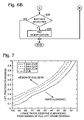
- FIGS. 6A–6B are a high level flowchart of a routine.
- FIGS. 2–5 and 7 – 9 are graphs illustrating experimental and control data.
- FIG. 1A shows a diagram of a system for operating a variable compression ratio internal combustion engine in accordance with an example embodiment of the present invention.
- the engine 110 shown in FIG. 1A is a gasoline four-stroke direct fuel injection (DFI) internal combustion engine having a plurality of cylinders (only one shown), each of the cylinders having a combustion chamber 111 and corresponding fuel injector 113 , spark plug 115 , intake manifold 124 , exhaust manifold 104 , and reciprocating piston 112 .
- the engine 110 can be any internal combustion engine, such as a port fuel injection (PFI) or diesel engine, having one or more reciprocating pistons as shown in FIG. 1A .
- PFI port fuel injection
- Each piston of the internal combustion engine is coupled to a fixed-length connecting rod 114 on one end, and to a crankpin 117 of a crankshaft 116 .
- position sensor 161 is coupled to compression ratio mechanism 170 for measuring compression ratio position.
- Exhaust manifold 104 is coupled to an emission control device 146 and exhaust gas sensor 148 .
- Emission control device 146 can be any type of three-way catalyst, such as a NOx adsorbent having various amounts of materials, such as precious metals (platinum, palladium, and rhodium) and/or barium and lanthanum.
- Exhaust gas sensor 148 can be a linear, or full range, air-fuel ratio sensor, such as a UEGO (Universal Exhaust Gas Oxygen Sensor), that produces a substantially linear output voltage versus oxygen concentration, or air-fuel ratio. Alternatively, it can be a switching type sensor, or HEGO (Heated Exhaust Gas Oxygen Sensor).
- UEGO Universal Exhaust Gas Oxygen Sensor
- the reciprocating piston 112 is further coupled to a compression ratio mechanism 170 that is operated by an electronic engine controller 160 to vary the compression ratio of the engine.
- “Compression ratio” includes the ratio of the volume in the cylinder 111 above the piston 112 when the piston is at bottom-dead-center (BDC) to the volume in the cylinder above the piston 112 when the piston 112 is at top-dead-center (TDC).
- the compression ratio mechanism 170 is operated to effect a change in the engine's compression ratio in accordance with one or more parameters, such as engine load and speed, for example.
- Such parameters are measured by appropriate sensors, such as a speed (RPM) sensor 158 , mass air flow (MAF) sensor 102 , pedal position sensor 140 , compression ratio sensor 160 , manifold temperature sensor 162 , and manifold pressure sensor ( 164 ), which are electronically coupled to the engine controller 160 .
- the compression ratio mechanism 170 can be one such as described in U.S. Pat. No. 6,595,187, for example. However, other types of compression ratio adjusting mechanisms can be used, such as one which provides a variable sized volume outside of the cylinder to vary compression ratio. Likewise, the mechanism for adjusting compression ratio can be hydraulic, electrical, electro-hydraulic, electromechanical, electromagnetic, or various others.
- the engine controller 160 includes a central processing unit (CPU) 162 having corresponding input/output ports 169 , read-only memory (ROM) 165 or any suitable electronic storage medium containing processor-executable instructions and calibration values, random-access memory (RAM) 166 , and a data bus 168 of any suitable configuration.
- the controller 160 receives signals from a variety of sensors coupled to the engine 110 and/or the vehicle, and controls the operation of the fuel injector 115 , which is positioned to inject fuel into a corresponding cylinder 111 in precise quantities as determined by the controller 160 .
- the controller 160 similarly controls the operation of the spark plugs 113 .
- engine 110 also has variable valve actuators 180 and 182 for actuating intake valve 120 and exhaust valve 118 , respectively.
- Controller 160 controls actuators 180 and 182 via signals EVL, EVT, IVL, IVT, representing exhaust valve lift, exhaust valve timing, intake valve lift, and intake valve timing, respectively.
- the actuators can independently adjust valve lift and valve timing of the valves. In one example, these can be electro-hydraulic actuators that allow cam-less engine operation. Alternatively, they can be electromagnetic actuators. In still another embodiment, separate electro-hydraulic actuators can be used to adjust cam timing and valve lift of the valves. Note that not all of the valves can have variable timing or lift. For example, one valve can have variable valve lift and the other can have variable valve timing.
- FIG. 1A illustrates a two valve engine, which can be operated either via the electronic valves as indicated, or via an overhead cam.
- a four valve per cylinder system can be used, with two intake and two exhaust valves (each of the same or different size).
- a three-valve per cylinder system can be used where two intake valves, and one exhaust valve are used.
- engine 110 does not have various parts indicated in FIG. 1A .
- the engine may not have the variable compression ratio mechanism and corresponding sensors and actuators.
- FIG. 1B shows engine 110 having a variable cam timing actuator.
- engine 110 is shows to be a direct injection spark ignited internal combustion engine, rather than the port fuel injection system illustrated in FIG. 1A , since either type of fuel injection can be used.
- combustion chamber 111 of engine 110 is shown in FIG. 1B including combustion chamber walls 32 with piston 112 positioned therein.
- piston 112 includes a recess or bowl (not shown) to help in forming stratified charges of air and fuel.
- Combustion chamber, or cylinder, 111 is shown communicating with intake manifold 124 and exhaust manifold 104 via respective intake valves 52 a and 52 b (not shown), and exhaust valves 54 a and 54 b (not shown).
- Fuel injector 66 is shown directly coupled to combustion chamber 111 for delivering liquid fuel directly therein in proportion to the pulse width of signal fpw received from controller 160 via conventional electronic driver 68 .
- Fuel is delivered to fuel injector 66 by a high pressure fuel system (not shown) including a fuel tank, fuel pumps, and a fuel rail. Note that the variable compression ratio system can also be included, but is not shown.
- Intake manifold 124 is shown communicating with throttle body 58 via throttle plate 62 .
- throttle plate 62 is coupled to electric motor 94 so that the position of throttle plate 62 is controlled by controller 160 via electric motor 94 .
- Signal TP from throttle position sensor 70 is used to measure throttle position for the feedback control.
- This configuration is commonly referred to as electronic throttle control (ETC) which is also utilized during idle speed control.
- ETC electronic throttle control
- a bypass air passageway is arranged in parallel with throttle plate 62 to control inducted airflow during idle speed control via a throttle control valve positioned within the air passageway.
- Controller 160 causes combustion chamber 111 to operate in either a homogeneous air/fuel mode or a stratified air/fuel mode by controlling injection timing.
- controller 160 activates fuel injector 66 during the engine compression stroke so that fuel is sprayed directly into the bowl of piston 112 .
- Stratified air/fuel layers are thereby formed.
- the strata closest to the spark plug contains a stoichiometric mixture or a mixture slightly rich of stoichiometry, and subsequent strata contain progressively leaner mixtures.
- controller 160 activates fuel injector 66 during the intake stroke so that a substantially homogeneous air/fuel mixture is formed when ignition power is supplied to spark plug 113 by ignition system 122 .
- Controller 160 controls the amount of fuel delivered by fuel injector 66 so that the homogeneous air/fuel mixture in chamber 111 can be selected to be at stoichiometry, a value rich of stoichiometry, or a value lean of stoichiometry.
- the stratified air/fuel mixture will always be at a value lean of stoichiometry, the exact air/fuel being a function of the amount of fuel delivered to combustion chamber 111 .
- An additional split mode of operation wherein additional fuel is injected during the exhaust stroke while operating in the stratified mode is also possible.
- controller 160 is a microcomputer including: microprocessor unit 162 , input/output ports 169 , an electronic storage medium for executable programs and calibration values shown as read only memory chip 165 in this particular example, random access memory 166 , and a data bus 168 .
- KAM keep alive memory
- Controller 160 is shown receiving various signals from sensors coupled to engine 110 , in addition to those signals previously discussed, including: measurement of inducted mass air flow (MAF) from mass air flow sensor 102 coupled to throttle body 58 ; engine coolant temperature (ECT) from temperature sensor 106 coupled to cooling sleeve 108 ; throttle position TP from throttle position sensor 70 ; and absolute Manifold Pressure Signal MAP from sensor 164 .
- Engine speed signal RPM is generated by controller 160 from a profile ignition pick-up (PIP) signal coupled to the crankshaft in a conventional manner and manifold pressure signal MAP provides an indication of engine load.
- PIP sensor which is also used as an engine speed sensor, produces a predetermined number of equally spaced pulses every revolution of the crankshaft.
- camshaft 130 of engine 110 is shown communicating with rocker arms 132 and 134 for actuating intake valves 52 a , 52 b and exhaust valve 54 a . 54 b .
- Camshaft 130 is directly coupled to housing 136 .
- Housing 136 forms a toothed wheel having a plurality of teeth 138 .
- Housing 136 is hydraulically coupled to an inner shaft (not shown), which is in turn directly linked to camshaft 130 via a timing chain (not shown). Therefore, housing 136 and camshaft 130 rotate at a speed substantially equivalent to the inner camshaft.
- the inner camshaft rotates at a constant speed ratio to crankshaft 116 .
- the relative position of camshaft 130 to crankshaft 116 can be varied by hydraulic pressures in advance chamber 142 and retard chamber 144 .
- advance chamber 142 By allowing high pressure hydraulic fluid to enter advance chamber 142 , the relative relationship between camshaft 130 and crankshaft 116 is advanced.
- intake valves 52 a , 52 b and exhaust valves 54 a , 54 b open and close at a time earlier than normal relative to crankshaft 116 .
- the relative relationship between camshaft 130 and crankshaft 116 is retarded.
- intake valves 52 a , 52 b and exhaust valves 54 a , 54 b open and close at a time later than normal relative to crankshaft 116 .
- Teeth 138 being coupled to housing 136 and camshaft 130 , allow for measurement of relative cam position via cam timing sensor 150 providing signal VCT to controller 160 .
- Teeth 1 , 2 , 3 , and 4 are preferably used for measurement of cam timing and are equally spaced (for example, in a V-8 dual bank engine, spaced 90 degrees apart from one another), while tooth 5 is preferably used for cylinder identification, as described later herein.
- controller 160 sends control signals (LACT,RACT) to conventional solenoid valves (not shown) to control the flow of hydraulic fluid either into advance chamber 142 , retard chamber 144 , or neither.
- Relative cam timing is measured using the method described in U.S. Pat. No. 5,548,995, which is incorporated herein by reference.
- the time, or rotation angle between the rising edge of the PIP signal and receiving a signal from one of the plurality of teeth 138 on housing 136 gives a measure of the relative cam timing.
- a measure of cam timing for a particular bank is received four times per revolution, with the extra signal used for cylinder identification.
- FIG. 1B shows a 4 valve per cylinder engine, where cam timing of the intake and exhaust valves is adjusted via a single dual overhead cam.
- a single overhead cam can adjust only intake valve timing, or only exhaust valve timing.
- a dual overhead cam can be used, each with variable timing to separately adjust intake and exhaust valve timing.
- an electro-hydraulically actuated variable valve lift actuator can be added to the system of FIG. 1B to provide variable valve lift control.
- VCT variable cam timing
- FIG. 2 is an example if the VCT (variable cam timing) actuator does not adjust to maintain IVO.
- An intake cam advance that maintains IVO near TDC at low lift may result in a valve to piston collision if the lift increases suddenly. As such, FIG. 2 shows how clearance can change as the valves and piston translate through the engine cycle.
- MCV minimum clearance violation
- FIG. 3 shows the uncoordinated results of this scenario. Specifically, FIG. 3 shows how a variation in valve timing and valve lift, even where the beginning and end positions both have sufficient clearance, can result in transient conditions of insufficient clearance (or clearance less than desired).
- FIG. 4 shows the un-coordinated results of this scenario. Specifically, FIG. 4 shows another example where, even though the two set-points (before and after) have sufficient clearance, due to variation in actuator speeds, there can be insufficient clearance during the transition between the two set-points.
- VCT and Lift Coordinator (labeled VCT — Lift — Coord, 512 ) is placed between the Powertrain Controller ( 510 ), that provides reference signals for VCT and lift, and actuator controllers (VCT — Controller and Lift — Controller, 514 and 516 ) that enforce the powertrain's reference signals.
- VCT and lift controllers are feedback controllers that use measurements of valve lift and cam timing ( 518 and 520 ) to generate actuator signals sent to the VCT and lift actuators ( 522 and 524 ).
- block 526 illustrates the engine model.
- the Powertrain Controller's reference signals are based on achieving required fuel economy, emissions, and torque output.
- the scheduled steady state lift and VCT should result in actuator positions that leave adequate clearance between the valve and piston.
- the routines described below reduce the chance that the clearance is not maintained during actuator transitions.
- the actuator controllers are designed to respond to the Powertrain Controller's reference signals by providing prompt changes in actuator position and to maintain these desired positions by rejecting disturbances that can alter the actuator's position.
- the actuator controllers are supplemented by the Lift Coordination sub-system to coordinate movement between lift and VCT to maintain valve to piston clearance.
- routines described below in the text and flowcharts may represent one or more of any number of processing strategies such as event-driven, interrupt-driven, multi-tasking, multi-threading, and the like. As such, various steps or functions illustrated may be performed in the sequence illustrated, in parallel, or in some cases omitted. Likewise, the order of processing is not necessarily required to achieve the features and advantages of the invention, but is provided for ease of illustration and description. Although not explicitly illustrated, one of ordinary skill in the art will recognize that one or more of the illustrated steps or functions may be repeatedly performed depending on the particular strategy being used. Further, these Figures graphically represent code to be programmed into the computer readable storage medium in controller 160 .
- step 610 the routine calculates the clearance for the current positions (operating conditions).
- the routine calculates a minimum clearance (MC).
- MC is created from a map that relates inputs of VCT and lift to an output of clearance.
- FIG. 7 shows data for a given engine/valve/cam combination.
- the graph shows that for a given minimum clearance there is curve that relates lift and VCT at TDC.
- High lift and advanced VCT result in less clearance (i.e., increased potential for collision), whereas lower lift and retarded VCT result in more clearance.
- the exact path of the curves is dependent on engine geometry.
- clearance Function — lift — vct — clr(lift, VCT, VCR)
- lift is either expressed as a fraction of maximum lift (used in this example) or a linear measurement of CVVL position
- VCT is the cam timing relative to TDC of the piston position of an induction stroke
- VCR is the current compression ratio at which the engine is operating
- clearance is the distance that exists between the piston at TDC and the intake valve.
- this function only contains values of clearance assuming the piston is at or near TDC.
- it can contain additional information when operating slightly away from TDC.
- the worst interference is assumed to be the TDC piston position.
- the VCT phase may result in a valve lift in which the greatest interference happens just before piston TDC.
- the absolute worst case would be TDC for the piston and “TDC” of the valve, but the limits of phasing might not allow that to occur, so the worst case may not be exactly TDC of the piston.
- the table data can be populated by locating the worst physically possible interference that can occur, which can be different than TDC piston.
- the worst case location of interference can vary depending on engine design, engine geometry, and other factors.
- step 618 the routine selects an appropriate actuator(s) to respond to potential MCV. This step is accomplished by checking the desired direction (or, in an alternative embodiment, the actual direction) of movement of each actuator and setting a flag if the actuator is moving in a direction that has the potential to reduce clearance, such as increasing lift or advancing VCT. If the actuator movement direction reduces clearance, the act — MCV flag is passed on as a signal that is specific to an actuator (VCT — MCV or lift — MCV). For the VCT actuator, if VCT>VCT — des then the routine sets the flag VCT — MCV to act — MCV. Otherwise, the routine sets the flag VCT — MCV to zero.
- VCT is the measured value of the VCT phasor and VCT — des is the Powertrain Controller VCT desired signal. This logic assumes that VCT position is negative for advance.
- Similar logic is employed for the lift actuator. Specifically, if the lift ⁇ lift — des, then the flag lift — MCV is set to act — MCV. Otherwise, the flag lift — MCV is set to zero.
- both the cam timing and valve lift are adjusted, or limited to a specific range or to be below a maximum value.
- the selection can take into account additional factors, or use alternative factors, such as the relative actuator responses. For example, if one actuator travels faster than the other in the particular operating conditions at issue, the faster actuator can be selected.
- step 620 the routine determines alternative actuator commands to reduce potential interference if MCV has occurred as indicated in step 612 .
- the routine can determine a limited range of travel for each of the actuators that will reduce potential interference. Still further, the routine can set a maximum advance angle for cam timing, and a maximum lift for valve lift. Also, the routine can also limit not only positions, or ranges of the cam actuator and/or lift actuator, but also the rate of change of the actuators. Further still, in yet another alternative embodiment, the routine can limit both the cam timing and valve lift actuators.
- routine replaces the chosen actuator's command with one that establishes MC:
- step 618 The decision as to which actuator to modify is accomplished by using VCT — MCV or lift — MCV from step 618 . If the actuator is not chosen, the Powertrain Controller's reference signal is passed on to the actuator position controller. If the actuator is chosen, the alternative command computed in step 620 is passed on to the actuator position controller instead.
- step 636 the routine determines if neither actuator is selected (i.e., neither actuator was moving in a direction to reduce valve lift). If so, the routine continues to step 638 where neither actuator is selected. This means either: (1) there is no danger of collision, or (2) there has been a clearance violation, but the normal scheduling has changed and now the actuators are moving away from the collision. In either scenario, interfering with the desired positions of the actuators would not likely alter the collision situation.
- the actuator will get to that normal position, and if it is collision prone but not commanded to move more, then the actuator will no longer satisfy the direction requirement and it will be set to the calculated min clearance.
- the scheduling attempts to go from one steady state place to another. As shown in FIG. 7 , that would be from one safe corner to another. However, the mismatched speeds of the actuators cause the path to go through clearance violation zone in FIG. 7 . So, when the actuators hit the minimum clearance curve, for example the 1.5 mm curve (where exactly this happens depends on the actuator speeds and commands), the actuators can be forced to track along the 1.5 mm curve until they break through to the new region of lift-VCT space where collision is unlikely. Here, they will occupy a position determined by best engine operation scheduling.
- adjustment provided above to reduce potential interference may affect engine output, such as engine torque or engine speed.
- adjustment can be made to compensate for any affect on engine output.
- throttle position can be adjusted to provide more or less engine torque to compensate for cam timing or lift adjustments.
- ignition timing changes/adjustments can also be used.
- fuel adjustments can be used.
- adjustments in cam timing or compression ratio can require corresponding adjustments in ignition timing to provide efficient operation.
- ignition timing may need to be adjusted during a limiting, or adjusting, of valve timing, valve lift, and/or compression ratio due to potential interference. In this way, overall efficient operation can be maintained, even when adjustments are made to reduce interference.
- the first case is where actuator(s) degrade with the sensors operating.
- the routine relies on VCT — Lift — Coord to halt potentially interfering directional movement of the working actuator. Multiple failures may require more intrusive action.
- the CVVL hardware design can also include a passive (spring) return system to position valve lift in a predetermined (e.g. low-lift) position.
- VCT Lift — Coord to halt lift increase that results in clearance violation.
- the VCT hardware can also include a passive (spring) return mechanism to position intake VCT at predetermined (e.g. full-retard) position.
- the VCT — Lift — Coord routine uses the clearance table (Function — lift — vct — clr) based on the measured VCR position to reduce any potential interference.
- the routine first determines if current conditions result in a violation. If so, the routine sets VCR to a low compression value. If there is still potential interference at the low compression position, the routine requests an engine shutdown.
- the routine determines if there is potential interference. If so, the routine requests engine shutdown operation.
- the second case is where a sensor (or sensors) has degraded and actuator operation is uncertain.
- the routine uses a back-up (redundant) lift sensor, if available.
- the routine sets compression ratio to a low value and/or retards VCT assuming maximal valve lift.
- the routine sets compression ratio to a low value, and/or reduces lift assuming fully advanced VCT as a substitute.
- VCR is in a high position and uses the corresponding clearance table to operates valve lift and VCT with the approach described in FIG. 6 , above.
- the routine adjusts compression ratio to a low compression, and send signals to the CVVL and VCT to reduce lift and retard timing.
- Data was generated using a model that uses crank angle to produce positions of the engine piston, intake, and exhaust valves relative to the center of the gasket that separates the cylinder head and the engine block.
- the data was generated with a relatively high compression of the engine, providing a large range of potential valve to piston interference.
- the VCT and CVVL actuators and the feedback controls that regulate these mechanisms was represented by first order filter structures in which the integrator in the structure, the value of which is the actuator position, can be initialized at the beginning of the simulation.
- the actuator speeds, set by gain before the integrator, are relatively high, so that the simulation can produce a large range of actuator movement in only a few engine cycles.
- the gain of the CVVL actuator is set to 20, and the gain VCT is set to 10 to demonstrate the coordination when the lift outruns VCT ( FIG. 8 plots results). In another case, the gain of the CVVL actuator was set to 10, and the gain VCT was set to 20 to demonstrate the coordination when the VCT outruns lift ( FIG. 9 plots results).
- FIG. 8 shows results with the lift actuator set to a high rate, the VCT actuator set to low a rate.
- the lift schedule goes from 0.3 to 1.0 of maximum lift, and VCT retards from 70 degrees advanced (indicated as ⁇ 70) to 0 degrees advanced.
- the figure shows how lift increases too fast for VCT retard, so the VCT Lift Coordinator interrupts the desired signal to the CVVL mechanism when the minimum clearance is violated (second row, dashed trace falls below dotted trace).
- the fourth row plot shows the lift commanded value (dotted) is jumping to the calculated MC lift position (dash-dot) when the lift — MCV flag is 1 (fifth row plot, dotted trace).
- the fourth row plot, solid trace shows the lift position, which progresses normally when at MC, and reduces towards MC when in violation.
- FIG. 9 shows results with the lift actuator set to a low rate, and the VCT actuator set to a high rate.
- the lift schedule goes from 0.9 to 0.3 of maximum lift, and VCT advances from 0 degrees advanced to ⁇ 70 degrees advanced.
- the VCT advances too fast for lift reduction, so the VCT Lift Coordinator interrupts the desired signal to the VCT mechanism when the minimum clearance is violated (second row, dashed trace falls below dotted trace).
- the third row plot shows the VCT commanded value (dotted) jumping to the calculated MC VCT (dash-dot) when the VCT halt flag is 1 (fifth row plot, dashed trace).
- the third row plot, solid trace shows the VCT, which progresses normally when at MC, and moves towards MC when in violation.
- the VCT has combustion frequency oscillation of +/ ⁇ 2 degrees about the average VCT position.
Abstract
Description
clearance—total=clearance—min+clearance—tolerance
VCT — at — MC=Function — VCT — for — MC(clearance — total, lift, VCR)
lift — at — MC=Function — lift — for — MC(clearance — total, VCT, VCR).
Claims (10)
Priority Applications (1)
| Application Number | Priority Date | Filing Date | Title |
|---|---|---|---|
| US10/714,682 US6994061B2 (en) | 2003-11-13 | 2003-11-13 | Computer readable storage medium for use with engine having variable valve actuator during degradation |
Applications Claiming Priority (1)
| Application Number | Priority Date | Filing Date | Title |
|---|---|---|---|
| US10/714,682 US6994061B2 (en) | 2003-11-13 | 2003-11-13 | Computer readable storage medium for use with engine having variable valve actuator during degradation |
Publications (2)
| Publication Number | Publication Date |
|---|---|
| US20050103291A1 US20050103291A1 (en) | 2005-05-19 |
| US6994061B2 true US6994061B2 (en) | 2006-02-07 |
Family
ID=34574032
Family Applications (1)
| Application Number | Title | Priority Date | Filing Date |
|---|---|---|---|
| US10/714,682 Expired - Lifetime US6994061B2 (en) | 2003-11-13 | 2003-11-13 | Computer readable storage medium for use with engine having variable valve actuator during degradation |
Country Status (1)
| Country | Link |
|---|---|
| US (1) | US6994061B2 (en) |
Cited By (20)
| Publication number | Priority date | Publication date | Assignee | Title |
|---|---|---|---|---|
| US20060070605A1 (en) * | 2004-01-21 | 2006-04-06 | Toyota Jidosha Kabushiki Kaisha | Internal combustion engine with variable compression ratio |
| US20070006832A1 (en) * | 2005-07-08 | 2007-01-11 | Jun-Mo Kang | Method and system to avoid piston-valve collision |
| US7167789B1 (en) * | 2005-05-16 | 2007-01-23 | Walt Froloff | Variable compression ratio internal combustion engine |
| US20150211394A1 (en) * | 2010-03-19 | 2015-07-30 | Eaton Corporation | Sensing and control of a variable valve actuation system |
| US20160252022A1 (en) * | 2013-10-23 | 2016-09-01 | Hitachi Automotive Systems, Ltd. | Control apparatus and method for internal combustion engine |
| US9581058B2 (en) | 2010-08-13 | 2017-02-28 | Eaton Corporation | Development of a switching roller finger follower for cylinder deactivation in internal combustion engines |
| US9644503B2 (en) | 2008-07-22 | 2017-05-09 | Eaton Corporation | System to diagnose variable valve actuation malfunctions by monitoring fluid pressure in a hydraulic lash adjuster gallery |
| US9664075B2 (en) | 2011-03-18 | 2017-05-30 | Eaton Corporation | Custom VVA rocker arms for left hand and right hand orientations |
| US9765657B2 (en) | 2010-03-19 | 2017-09-19 | Eaton Corporation | System, method and device for rocker arm position sensing |
| US9822673B2 (en) | 2010-03-19 | 2017-11-21 | Eaton Corporation | Latch interface for a valve actuating device |
| US9869211B2 (en) | 2014-03-03 | 2018-01-16 | Eaton Corporation | Valve actuating device and method of making same |
| US9938865B2 (en) | 2008-07-22 | 2018-04-10 | Eaton Corporation | Development of a switching roller finger follower for cylinder deactivation in internal combustion engines |
| US9964005B2 (en) | 2008-07-22 | 2018-05-08 | Eaton Corporation | Method for diagnosing variable valve actuation malfunctions by monitoring fluid pressure in a control gallery |
| US10087790B2 (en) | 2009-07-22 | 2018-10-02 | Eaton Corporation | Cylinder head arrangement for variable valve actuation rocker arm assemblies |
| US10119429B2 (en) | 2010-03-19 | 2018-11-06 | Eaton Corporation | Systems, methods, and devices for valve stem position sensing |
| US10180087B2 (en) | 2010-03-19 | 2019-01-15 | Eaton Corporation | Rocker arm assembly and components therefor |
| US10415439B2 (en) | 2008-07-22 | 2019-09-17 | Eaton Intelligent Power Limited | Development of a switching roller finger follower for cylinder deactivation in internal combustion engines |
| US10570786B2 (en) | 2010-03-19 | 2020-02-25 | Eaton Intelligent Power Limited | Rocker assembly having improved durability |
| US11181013B2 (en) | 2009-07-22 | 2021-11-23 | Eaton Intelligent Power Limited | Cylinder head arrangement for variable valve actuation rocker arm assemblies |
| US11788439B2 (en) | 2010-03-19 | 2023-10-17 | Eaton Intelligent Power Limited | Development of a switching roller finger follower for cylinder deactivation in internal combustion engines |
Families Citing this family (4)
| Publication number | Priority date | Publication date | Assignee | Title |
|---|---|---|---|---|
| US6910449B2 (en) * | 2002-12-30 | 2005-06-28 | Ford Global Technologies, Llc | Method for auto-ignition operation and computer readable storage device for use with an internal combustion engine |
| EP1873377B1 (en) * | 2006-06-28 | 2010-03-17 | Ford Global Technologies, LLC | An internal combustion engine comprising a variable valve lift profile system and a method for controlling valve lift profile shifting |
| JP5515772B2 (en) * | 2010-01-21 | 2014-06-11 | トヨタ自動車株式会社 | Control device for variable valve mechanism |
| KR101807008B1 (en) * | 2012-07-20 | 2017-12-08 | 현대자동차 주식회사 | Control method for cvvl engine |
Citations (8)
| Publication number | Priority date | Publication date | Assignee | Title |
|---|---|---|---|---|
| US5596956A (en) | 1994-12-16 | 1997-01-28 | Honda Giken Kogyo Kabushiki Kaisha | Electromagnetically driven valve control system for internal combustion engines |
| US6202609B1 (en) | 1997-10-23 | 2001-03-20 | Continental Isad Electronic Systems Gmbh & Co. Kg | Electromagnetic control device |
| US6230675B1 (en) | 1999-05-19 | 2001-05-15 | Honda Giken Kogyo Kabushiki Kaisha | Intake valve lift control system |
| US6401675B1 (en) | 1999-02-15 | 2002-06-11 | Unisia Jecs Corporation | Variable valve gear device of internal combustion engine |
| US20030093214A1 (en) | 2001-11-09 | 2003-05-15 | Jankovic Mrdjan J. | System and method for selecting a camshaft in an engine having dual camshafts |
| US6575128B2 (en) * | 2001-05-09 | 2003-06-10 | Unisia Jecs Corporation | Variable-valve-actuation apparatus for internal combustion engine |
| US6595187B1 (en) | 2000-10-12 | 2003-07-22 | Ford Global Technologies, Llc | Control method for internal combustion engine |
| US20030192495A1 (en) | 2002-04-15 | 2003-10-16 | Ford Global Technologies, Inc. | Cam synchronization algorithm for engine with variable cam timing |
-
2003
- 2003-11-13 US US10/714,682 patent/US6994061B2/en not_active Expired - Lifetime
Patent Citations (8)
| Publication number | Priority date | Publication date | Assignee | Title |
|---|---|---|---|---|
| US5596956A (en) | 1994-12-16 | 1997-01-28 | Honda Giken Kogyo Kabushiki Kaisha | Electromagnetically driven valve control system for internal combustion engines |
| US6202609B1 (en) | 1997-10-23 | 2001-03-20 | Continental Isad Electronic Systems Gmbh & Co. Kg | Electromagnetic control device |
| US6401675B1 (en) | 1999-02-15 | 2002-06-11 | Unisia Jecs Corporation | Variable valve gear device of internal combustion engine |
| US6230675B1 (en) | 1999-05-19 | 2001-05-15 | Honda Giken Kogyo Kabushiki Kaisha | Intake valve lift control system |
| US6595187B1 (en) | 2000-10-12 | 2003-07-22 | Ford Global Technologies, Llc | Control method for internal combustion engine |
| US6575128B2 (en) * | 2001-05-09 | 2003-06-10 | Unisia Jecs Corporation | Variable-valve-actuation apparatus for internal combustion engine |
| US20030093214A1 (en) | 2001-11-09 | 2003-05-15 | Jankovic Mrdjan J. | System and method for selecting a camshaft in an engine having dual camshafts |
| US20030192495A1 (en) | 2002-04-15 | 2003-10-16 | Ford Global Technologies, Inc. | Cam synchronization algorithm for engine with variable cam timing |
Cited By (33)
| Publication number | Priority date | Publication date | Assignee | Title |
|---|---|---|---|---|
| US20060070605A1 (en) * | 2004-01-21 | 2006-04-06 | Toyota Jidosha Kabushiki Kaisha | Internal combustion engine with variable compression ratio |
| US7422004B2 (en) * | 2004-01-21 | 2008-09-09 | Toyota Jidosha Kabushiki Kaisha | Internal combustion engine with variable compression ratio |
| US20080306676A1 (en) * | 2004-01-21 | 2008-12-11 | Toyota Jidosha Kabushiki Kaisha | Internal combustion engine with variable compression ratio |
| US7840335B2 (en) | 2004-01-21 | 2010-11-23 | Toyota Jidosha Kabushiki Kaisha | Internal combustion engine with variable compression ratio |
| US7167789B1 (en) * | 2005-05-16 | 2007-01-23 | Walt Froloff | Variable compression ratio internal combustion engine |
| US20070006832A1 (en) * | 2005-07-08 | 2007-01-11 | Jun-Mo Kang | Method and system to avoid piston-valve collision |
| US7178493B2 (en) * | 2005-07-08 | 2007-02-20 | Gm Global Technology Operations, Inc. | Method and system to avoid piston-valve collision |
| US10415439B2 (en) | 2008-07-22 | 2019-09-17 | Eaton Intelligent Power Limited | Development of a switching roller finger follower for cylinder deactivation in internal combustion engines |
| US9938865B2 (en) | 2008-07-22 | 2018-04-10 | Eaton Corporation | Development of a switching roller finger follower for cylinder deactivation in internal combustion engines |
| US9644503B2 (en) | 2008-07-22 | 2017-05-09 | Eaton Corporation | System to diagnose variable valve actuation malfunctions by monitoring fluid pressure in a hydraulic lash adjuster gallery |
| US9964005B2 (en) | 2008-07-22 | 2018-05-08 | Eaton Corporation | Method for diagnosing variable valve actuation malfunctions by monitoring fluid pressure in a control gallery |
| US11181013B2 (en) | 2009-07-22 | 2021-11-23 | Eaton Intelligent Power Limited | Cylinder head arrangement for variable valve actuation rocker arm assemblies |
| US10087790B2 (en) | 2009-07-22 | 2018-10-02 | Eaton Corporation | Cylinder head arrangement for variable valve actuation rocker arm assemblies |
| US10180087B2 (en) | 2010-03-19 | 2019-01-15 | Eaton Corporation | Rocker arm assembly and components therefor |
| US9702279B2 (en) * | 2010-03-19 | 2017-07-11 | Eaton Corporation | Sensing and control of a variable valve actuation system |
| US11788439B2 (en) | 2010-03-19 | 2023-10-17 | Eaton Intelligent Power Limited | Development of a switching roller finger follower for cylinder deactivation in internal combustion engines |
| US9885258B2 (en) | 2010-03-19 | 2018-02-06 | Eaton Corporation | Latch interface for a valve actuating device |
| US11530630B2 (en) | 2010-03-19 | 2022-12-20 | Eaton Intelligent Power Limited | Systems, methods, and devices for rocker arm position sensing |
| US9915180B2 (en) | 2010-03-19 | 2018-03-13 | Eaton Corporation | Latch interface for a valve actuating device |
| US9765657B2 (en) | 2010-03-19 | 2017-09-19 | Eaton Corporation | System, method and device for rocker arm position sensing |
| US10570786B2 (en) | 2010-03-19 | 2020-02-25 | Eaton Intelligent Power Limited | Rocker assembly having improved durability |
| US20150211394A1 (en) * | 2010-03-19 | 2015-07-30 | Eaton Corporation | Sensing and control of a variable valve actuation system |
| US9822673B2 (en) | 2010-03-19 | 2017-11-21 | Eaton Corporation | Latch interface for a valve actuating device |
| US10119429B2 (en) | 2010-03-19 | 2018-11-06 | Eaton Corporation | Systems, methods, and devices for valve stem position sensing |
| US10890086B2 (en) | 2010-03-19 | 2021-01-12 | Eaton Intelligent Power Limited | Latch interface for a valve actuating device |
| US11085338B2 (en) | 2010-03-19 | 2021-08-10 | Eaton Intelligent Power Limited | Systems, methods and devices for rocker arm position sensing |
| US9581058B2 (en) | 2010-08-13 | 2017-02-28 | Eaton Corporation | Development of a switching roller finger follower for cylinder deactivation in internal combustion engines |
| US9664075B2 (en) | 2011-03-18 | 2017-05-30 | Eaton Corporation | Custom VVA rocker arms for left hand and right hand orientations |
| US10329970B2 (en) | 2011-03-18 | 2019-06-25 | Eaton Corporation | Custom VVA rocker arms for left hand and right hand orientations |
| US20160252022A1 (en) * | 2013-10-23 | 2016-09-01 | Hitachi Automotive Systems, Ltd. | Control apparatus and method for internal combustion engine |
| US9903301B2 (en) * | 2013-10-23 | 2018-02-27 | Hitachi Automotive Systems, Ltd. | Control apparatus with range control to suppress interference for internal combustion engine, and method thereof |
| US9995183B2 (en) | 2014-03-03 | 2018-06-12 | Eaton Corporation | Valve actuating device and method of making same |
| US9869211B2 (en) | 2014-03-03 | 2018-01-16 | Eaton Corporation | Valve actuating device and method of making same |
Also Published As
| Publication number | Publication date |
|---|---|
| US20050103291A1 (en) | 2005-05-19 |
Similar Documents
| Publication | Publication Date | Title |
|---|---|---|
| US6994061B2 (en) | Computer readable storage medium for use with engine having variable valve actuator during degradation | |
| US6938593B2 (en) | Computer readable storage medium for use with engine having variable valve actuator | |
| US7314041B2 (en) | EGR control system for internal combustion engine | |
| US8150605B2 (en) | Coordination of variable cam timing and variable displacement engine systems | |
| EP2096281B1 (en) | Internal combustion engine control method, internal combustion engine system and corresponding computer program product | |
| EP1431548B1 (en) | Intake control apparatus for internal combustion engine | |
| US6470869B1 (en) | Direct injection variable valve timing engine control system and method | |
| US7152578B2 (en) | Valve characteristic controlling apparatus and method for internal combustion engine | |
| CN105626274B (en) | Method and system for air charge estimation | |
| US20160010568A1 (en) | Selectively deactivatable engine cylinder | |
| US7137367B2 (en) | Control apparatus and control method for internal combustion engine valve actuation | |
| US6715476B2 (en) | System and method for exhaust gas recirculation control | |
| EP1418329B1 (en) | A method and system for controlling an engine | |
| US7690341B2 (en) | Engine intake valve timing control apparatus | |
| US20030196619A1 (en) | Valve condition control system for an internal combustion engine and control method thereof | |
| US9765705B2 (en) | Two-step valvetrain preposition control strategy | |
| EP1396613B1 (en) | Valve timing control system for internal combustion engine | |
| JP4841382B2 (en) | Internal combustion engine | |
| JP2007162664A (en) | Valve operation angle variable control device for internal combustion engine | |
| JP5092956B2 (en) | Method for controlling internal combustion engine for vehicle and internal combustion engine system | |
| JP5169682B2 (en) | Method for controlling internal combustion engine and internal combustion engine system | |
| US8620562B2 (en) | Variable valve system control apparatus | |
| JP5151613B2 (en) | Internal combustion engine control method and internal combustion engine system | |
| JP5012565B2 (en) | Internal combustion engine control method and internal combustion engine system | |
| JP4765896B2 (en) | Direct-injection spark ignition internal combustion engine |
Legal Events
| Date | Code | Title | Description |
|---|---|---|---|
| AS | Assignment |
Owner name: FORD GLOBAL TECHNOLOGIES, LLC, MICHIGAN Free format text: ASSIGNMENT OF ASSIGNORS INTEREST;ASSIGNOR:FORD MOTOR COMPANY;REEL/FRAME:014721/0661 Effective date: 20031113 |
|
| AS | Assignment |
Owner name: FORD MOTOR COMPANY, MICHIGAN Free format text: ASSIGNMENT OF ASSIGNORS INTEREST;ASSIGNORS:MAGNER, STEPHEN W.;JANKOVIC, MRDJAN J.;REEL/FRAME:015568/0452 Effective date: 20031113 |
|
| STCF | Information on status: patent grant |
Free format text: PATENTED CASE |
|
| FPAY | Fee payment |
Year of fee payment: 4 |
|
| FPAY | Fee payment |
Year of fee payment: 8 |
|
| FPAY | Fee payment |
Year of fee payment: 12 |