JP4765896B2 - Direct-injection spark ignition internal combustion engine - Google Patents
Direct-injection spark ignition internal combustion engine Download PDFInfo
- Publication number
- JP4765896B2 JP4765896B2 JP2006295046A JP2006295046A JP4765896B2 JP 4765896 B2 JP4765896 B2 JP 4765896B2 JP 2006295046 A JP2006295046 A JP 2006295046A JP 2006295046 A JP2006295046 A JP 2006295046A JP 4765896 B2 JP4765896 B2 JP 4765896B2
- Authority
- JP
- Japan
- Prior art keywords
- fuel injection
- lift amount
- valve
- region
- load
- Prior art date
- Legal status (The legal status is an assumption and is not a legal conclusion. Google has not performed a legal analysis and makes no representation as to the accuracy of the status listed.)
- Expired - Fee Related
Links
Images


Description
本発明は、吸気弁のリフト量を変化させることができる可変動弁装置を備える直噴火花点火式内燃機関に関する。 The present invention relates to a direct-injection spark-ignition internal combustion engine including a variable valve device that can change a lift amount of an intake valve.
特許文献1には、直噴火花点火式内燃機関において、始動時及び始動直後に、吸気弁のバルブリフト量(及びバルブ作動角)を小さくし、かつ吸気弁のバルブタイミングを遅らせて、吸気弁閉時期を固定したまま、吸気弁開時期を上死点以降かつ排気弁閉時期以降へ遅らせることにより、燃焼室内の負圧が発達してから一気に吸入することで、吸気流速を高める一方、燃料噴射時期を下死点近傍まで遅らせて、最大流速の状態で燃料噴射を行うことにより、燃料の微粒化促進を狙うようにしたものが開示されている。
しかしながら、吸気弁のリフト量が小さいときは、吸気流速は高まるものの、吸気は吸気弁の傘裏に沿って燃焼室内に入り、そのまま燃焼室壁面近傍をこれに沿って進行することで大きな抵抗を受けると共に、燃焼室の上面中央部や側面に衝突することで、減衰も早いことから、吸気流動が保存されにくいことがわかってきた。
このため、吸気弁のリフト量が小さいときは、噴射燃料の気化・拡散が悪化し、筒内混合気分布にムラができ、燃料噴射時期を遅くすると、これらがより顕著となる。
However, when the lift amount of the intake valve is small, the intake flow velocity increases, but the intake air enters the combustion chamber along the back of the intake valve, and travels along the wall of the combustion chamber as it is. At the same time, it has been found that the intake flow is difficult to be preserved because it quickly attenuates by colliding with the center and side of the upper surface of the combustion chamber.
For this reason, when the lift amount of the intake valve is small, the vaporization / diffusion of the injected fuel worsens, the in-cylinder mixture distribution becomes uneven, and these become more prominent when the fuel injection timing is delayed.
従って、例えば、可及的なノンスロットル運転を実現すべく、負荷に応じて吸気弁のリフト量を制御するような場合、低負荷領域で吸気弁のリフト量が小さくなると、上記と同様の理由で、噴射燃料の気化・拡散が悪化し、混合気の均質度の悪化により、燃焼安定度が悪化する。
本発明は、このような実状に鑑み、吸気流動が保存されにくい吸気弁の低リフト量状態のときの混合気の均質度を向上させて、燃焼安定性を確保することを目的とする。
Therefore, for example, when the lift amount of the intake valve is controlled in accordance with the load in order to realize the possible non-throttle operation, if the lift amount of the intake valve becomes small in the low load region, the same reason as above Thus, the vaporization / diffusion of the injected fuel deteriorates, and the combustion stability deteriorates due to the deterioration of the homogeneity of the mixture.
In view of such a situation, an object of the present invention is to improve the homogeneity of an air-fuel mixture when the intake valve is in a low lift amount state in which intake flow is difficult to be preserved, and to ensure combustion stability.
本発明は、燃焼室内に直接燃料を噴射する燃料噴射弁と、吸気弁のリフト量を変化させることができる可変動弁装置とを備える直噴火花点火式内燃機関において、The present invention relates to a direct injection spark ignition internal combustion engine including a fuel injection valve that directly injects fuel into a combustion chamber and a variable valve gear that can change a lift amount of an intake valve.
吸気弁のリフト量に応じて、燃料噴射時期を変更し、高リフト量の領域では、排気上死点後に1回燃料噴射を行い、低リフト量の領域では、排気上死点前に1回燃料噴射を行い、前記高リフト量の領域と前記低リフト量の領域との間の中リフト量の領域では、排気上死点を挟んでその前後に2回燃料噴射を行う燃料噴射時期設定手段を設けたことを特徴としている。 The fuel injection timing is changed according to the lift amount of the intake valve, and in the high lift region, fuel injection is performed once after the exhaust top dead center, and in the low lift region, once before the exhaust top dead center. Fuel injection timing setting means for performing fuel injection and performing fuel injection twice before and after the exhaust top dead center in the middle lift amount region between the high lift amount region and the low lift amount region It is characterized by providing.
本発明によれば、吸気流動が保存されにくい低リフト量のときに排気上死点前へと燃料噴射時期を早めることで、点火時期までの気化時間をかせぐことができ、混合気の均質度を向上させることができる。また中リフト量の領域では、燃料噴射を排気上死点前後の2回に分割することで、燃焼安定度とスモーク性能とを両立させることができる。 According to the present invention, the fuel injection timing is advanced before the exhaust top dead center when the intake air flow is a low lift amount where it is difficult to preserve, whereby the vaporization time until the ignition timing can be gained, and the homogeneity of the air-fuel mixture Can be improved. In the middle lift range, the fuel injection is divided into two times before and after exhaust top dead center, so that both combustion stability and smoke performance can be achieved.
以下に本発明の実施の形態を図面に基づいて説明する。
図1は本発明の一実施形態を示す内燃機関(エンジン)のシステム図である。
シリンダヘッド1、シリンダブロック2及びピストン3によって画成される燃焼室4は、吸気弁5を介して吸気ポート6と接続され、また排気弁7を介して排気ポート8と接続されている。吸気弁5及び排気弁7の開閉時期は、それぞれ、可変動弁装置9、10により制御可能である。
Embodiments of the present invention will be described below with reference to the drawings.
FIG. 1 is a system diagram of an internal combustion engine (engine) showing an embodiment of the present invention.
A
各可変動弁装置9、10としては、例えば、クランク軸とカム軸との回転位相を変更して吸・排気弁のバルブタイミング(バルブ作動角の中心位相)を可変制御可能なバルブタイミング可変装置(VTC装置)と、バルブ作動角(開期間)及びバルブリフト量を連続的に可変制御可能なバルブ作動角及びバルブリフト連続可変装置(VEL装置)とを組み合わせて用いる。この他、VTC装置と、カム切換えによりバルブリフト量を複数段に切換可能なバルブリフト可変装置(VVL装置)とを組み合わせて用いてもよいし、吸・排気弁を電磁アクチュエータにより駆動する電磁駆動弁装置(EMV装置)を用いてもよい。いずれにしても、吸気弁5のリフト量を変化させることができる可変動弁装置であればよい。
As each of the
燃焼室4内には、燃料噴射弁11と、点火プラグ12とが臨んでいる。
吸気通路13には、電制スロットル弁14が設けられている。
可変動弁装置9、10、燃料噴射弁11、点火プラグ12、及び、電制スロットル弁14の作動は、エンジンコントロールユニット(ECU)15により制御される。
ECU15には、クランク角センサ(図示せず)により検出されるエンジン回転数Ne、アクセル開度センサ(図示せず)により検出されるアクセル開度APO、エアフローメータ(図示せず)により検出される吸入空気量Qa等の情報が入力されている。
A
An
The operations of the
The
本実施形態のエンジンでは、少なくとも所定の運転条件において、電制スロットル弁14を略全開に保持しつつ(ノンスロットル状態)、負荷に応じて、比例的に、吸気弁5のリフト量(及び開期間)を制御することで、吸入空気量を制御し、これに対応した量の燃料を燃料噴射弁11より噴射供給することで、実質的なノンスロットル運転を実現する。
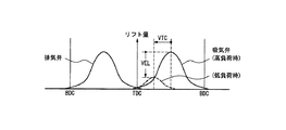
尚、可変動弁装置9により、特にVTC装置とVEL装置との組み合わせにより、負荷に応じて吸気弁5のリフト量を制御する際は、図2に示すように、吸気弁5の通常のリフト特性(図示実線)を高負荷時のリフト特性とし、これに対し、負荷が小さくなるほど、VTC装置によりバルブ作動角の中心位相を進角すると共にVEL装置によりバルブリフト量(及びバルブ作動角)を小さくして、図示点線のような、低負荷時のリフト特性にする。
In the engine according to the present embodiment, the lift amount (and the open amount) of the intake valve 5 is proportionally proportional to the load while the
When the lift amount of the intake valve 5 is controlled according to the load by the variable valve operating device 9, in particular by the combination of the VTC device and the VEL device, as shown in FIG. The characteristic (solid line in the figure) is the lift characteristic at high load. On the other hand, the smaller the load, the more the valve phase angle (and valve operating angle) is increased by the VEL device while the VTC device advances the central phase of the valve operating angle. The lift characteristic is reduced to a low load characteristic as shown by the dotted line in the figure.
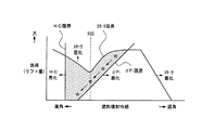
図3および図4は本発明の参考例を示すもので、図3は、縦軸に負荷(=吸気弁のリフト量)をとり、横軸に燃料噴射時期をとって、成立する範囲にスマッチングを付している。
負荷が小さくなるほど、吸気弁のリフト量が小さくなり、前述の理由により吸気流動が保存されにくいことから、噴射燃料の気化、拡散が悪化し、燃焼安定度σPiが悪化するので、これを回避すべく、燃料噴射時期を早めて、噴射燃料が気化、拡散する時間を確保する必要ある。それ故、負荷(=リフト量)が小さくなるほど燃料噴射時期を進角させる必要があるという燃焼安定度限界(σPi限界)があり、この限界線より遅角側では燃焼安定度(σPi)が悪化する。
3 and 4 show a reference example of the present invention . In FIG. 3, the vertical axis indicates the load (= lift amount of the intake valve), the horizontal axis indicates the fuel injection timing, and the range is satisfied. Matching is attached.
As the load decreases, the lift amount of the intake valve decreases, and the intake flow is less likely to be preserved for the reasons described above, so the vaporization and diffusion of the injected fuel deteriorates and the combustion stability σPi deteriorates. Therefore, it is necessary to advance the fuel injection timing to ensure time for the injected fuel to vaporize and diffuse. Therefore, there is a combustion stability limit (σPi limit) that the fuel injection timing needs to be advanced as the load (= lift amount) decreases, and the combustion stability (σPi) deteriorates on the retard side from this limit line. To do.
また、気化・拡散時間を稼ぐためには燃料噴射時期を進角させる方がよいが、負荷が高くなると、噴射量が増え、排気上死点(TDC)付近で一定量以上の燃料噴射を行うと、ピストンへの付着量が多くなり、スモークが発生する。従って、TDC付近の燃料噴射に一定の制約があり、これがスモーク限界であり、この限界線より高負荷側ではスモークが悪化する。尚、噴射時期を極端に遅くした場合も、スモークが悪化する。 In order to increase the vaporization / diffusion time, it is better to advance the fuel injection timing. However, when the load increases, the injection amount increases and a fuel injection of a certain amount or more is performed near the exhaust top dead center (TDC). As a result, the amount of adhesion to the piston increases and smoke is generated. Therefore, there is a certain restriction on the fuel injection in the vicinity of TDC, which is the smoke limit, and the smoke worsens on the high load side from this limit line. Note that smoke is also deteriorated when the injection timing is extremely delayed.
また、燃料噴射時期は、排気弁閉時期との関係で、進角しすぎると、噴射燃料がそのまま排気弁から排出されて、HCが悪化するので、噴射燃料が排気弁に達するまでの時間(距離)を考慮して、排気弁閉時期よりやや進角させた位置以降に噴射する必要がある。これが排気弁閉時期との関係で決まるHC限界であり、この限界線より進角側ではHCが悪化する。 In addition, the fuel injection timing is related to the exhaust valve closing timing. If the fuel injection timing is advanced too much, the injected fuel is discharged from the exhaust valve as it is and the HC deteriorates, so the time until the injected fuel reaches the exhaust valve ( In consideration of the distance), it is necessary to inject after the position slightly advanced from the exhaust valve closing timing. This is the HC limit determined by the relationship with the exhaust valve closing timing, and HC worsens on the advance side from this limit line.
従って、エンジンの特性上、図3のようなσPi限界、スモーク限界、HC限界を有する場合は、σPi限界のラインに沿って、負荷(=リフト量)に応じて、燃料噴射時期を変更し、負荷(=リフト量)が小さくなるほど、図中の☆印のように、燃料噴射時期を進角させる。言い換えれば、高リフト量の領域で、TDC後に燃料噴射を行わせ、低リフト量の領域で、TDC前に燃料噴射を行わせる。 Therefore, if the engine has the σPi limit, the smoke limit, and the HC limit as shown in FIG. 3, the fuel injection timing is changed according to the load (= lift amount) along the σPi limit line, As the load (= lift amount) decreases, the fuel injection timing is advanced as indicated by the asterisk in the figure. In other words, fuel injection is performed after TDC in the high lift amount region, and fuel injection is performed before TDC in the low lift amount region.
この場合の制御フローチャートを図4に示す。
S1で、負荷(=リフト量)を読込む。
S2で、図3に示したようなテーブル(☆印に沿うテーブルデータ)を参照し、負荷(=リフト量)に応じて、燃料噴射時期を設定し、制御する。この部分が燃料噴射時期設定手段に相当する。
A control flowchart in this case is shown in FIG.
In S1, load (= lift amount) is read.
In S2, a table (table data along the ☆ mark) as shown in FIG. 3 is referred to, and the fuel injection timing is set and controlled according to the load (= lift amount). This part corresponds to fuel injection timing setting means.
この例によれば、吸気弁のリフト量が小さくなるほど、燃料噴射時期を進角させることにより、及び/又は、高リフト量の領域で、排気上死点後に燃料噴射を行わせ、低リフト量の領域で、排気上死点前に燃料噴射を行わせることにより、燃焼安定度(噴射燃料の気化・拡散促進)とスモーク限界(ピストンへの燃料付着防止)とを両立させることができる。 According to this example , as the lift amount of the intake valve becomes smaller, the fuel injection timing is advanced and / or in the region of the high lift amount, fuel injection is performed after exhaust top dead center, and the low lift amount In this region, by performing fuel injection before exhaust top dead center, it is possible to achieve both combustion stability (evaporation and diffusion promotion of injected fuel) and smoke limit (prevention of fuel adhesion to the piston).
次に本発明の実施形態について説明する。
図5は、エンジンの特性により、スモーク限界が異なり、排気上死点(TDC)付近の1回噴射が成立しない場合を示してる。
従って、エンジンの特性上、図5のようなσPi限界、スモーク限界、HC限界を有する場合は、基本的には、σPi限界のラインに沿って、負荷(=リフト量)に応じて、燃料噴射時期を変更し、負荷(=リフト量)が小さくなるほど、図中の☆印のように、燃料噴射時期を進角させるが、高リフトの領域で、TDC後に、低リフトの領域で、TDC後に、それぞれ1回燃料噴射を行わせる一方、前記高リフトの領域と前記低リフトの領域との間の中リフトの領域で、TDCを挟んでその前後に2回燃料噴射を行わせる(★印)。すなわち、TDC付近でのスモーク限界により1回噴射が困難となる中リフトの領域では、燃料噴射を2回に分割し、TDC前と後に少量ずつ噴射することで、燃焼安定度(噴射燃料の気化・拡散促進)とスモーク性能(ピストンへの燃料付着防止)とを両立させるのである。
It will be described implementation form of the present invention.
FIG. 5 shows a case where the smoke limit differs depending on the characteristics of the engine, and one-time injection near the exhaust top dead center (TDC) is not established.
Therefore, in the case of having the σPi limit, smoke limit, and HC limit as shown in FIG. 5 due to the characteristics of the engine, basically, fuel injection is performed along the σPi limit line according to the load (= lift amount). As the load is changed and the load (= lift amount) becomes smaller, the fuel injection timing is advanced as indicated by the asterisk in the figure. However, in the high lift region, after TDC, in the low lift region, after TDC Each fuel injection is performed once, while in the middle lift region between the high lift region and the low lift region, fuel injection is performed twice before and after the TDC (*). . In other words, in the middle lift region where single injection is difficult due to the smoke limit in the vicinity of TDC, the fuel injection is divided into two parts and injected in small amounts before and after TDC, so that the combustion stability (vaporization of injected fuel)・ Achieving both diffusion promotion and smoke performance (preventing fuel adhesion to the piston).
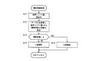
この場合の制御フローチャートを図6に示す。
S11では、負荷(=リフト量)を読込む。
S12で、図5に示したようなテーブル(☆印に沿うテーブルデータと★印の2回噴射用のデータ)を参照し、負荷(=リフト量)に応じて、燃料噴射時期と噴射回数とを設定する。この部分が燃料噴射時期設定手段に相当する。
A control flowchart in this case is shown in FIG.
In S11, the load (= lift amount) is read.
In S12, referring to the table as shown in FIG. 5 (table data along the ☆ mark and data for double injection marked with ★), the fuel injection timing and the number of injections are determined according to the load (= lift amount). Set. This part corresponds to fuel injection timing setting means.
S13では、噴射回数=2(2回噴射)か否かを判定し、NOの場合は、S14へ進んで1回噴射を行う。YESの場合は、S15へ進んで2回噴射(分割噴射)を行う。
本実施形態によれば、高リフト量の領域で、排気上死点後に1回燃料噴射を行わせ、低リフト量の領域で、排気上死点前に1回燃料噴射を行わせ、前記高リフト量の領域と前記低リフト量の領域との間の中リフト量の領域で、排気上死点を挟んでその前後に2回燃料噴射を行わせることにより、上死点付近での燃料噴射がスモーク限界から禁止されるような場合でも、燃焼安定度(噴射燃料の気化・拡散促進)とスモーク性能(ピストンへの燃料付着防止)とを両立させることができる。
In S13, it is determined whether or not the number of injections = 2 (two injections). If NO, the process proceeds to S14 and one injection is performed. In the case of YES, it progresses to S15 and performs 2 times injection (split injection).
According to this embodiment, fuel injection is performed once after the exhaust top dead center in the region of the high lift amount, and fuel injection is performed once before exhaust top dead center in the region of the low lift amount. By injecting fuel twice before and after the exhaust top dead center in the middle lift amount region between the lift amount region and the low lift amount region, fuel injection near the top dead center Even when the fuel is prohibited from the smoke limit, both combustion stability (acceleration / diffusion promotion of injected fuel) and smoke performance (prevention of fuel adhesion to the piston) can be achieved.
尚、以上では、可変動弁装置を用いて、負荷に応じて、低負荷ほど吸気弁のリフト量を小さくするように制御する場合について説明したが、必ずしもこれに限るものではなく、吸気弁のリフト量を制御するもの一般に適用可能である。 In the on or more, with a variable valve device, according to the load, there has been described a case of controlling so as to reduce the lift amount of the intake valve as the low load, it is not necessarily limited to this, the intake valve It is generally applicable to those that control the lift amount.
4 燃焼室
5 吸気弁
7 排気弁
9、10 可変動弁装置
11 燃料噴射弁
12 点火プラグ
15 ECU
4 Combustion chamber 5 Intake valve 7
Claims (2)
吸気弁のリフト量に応じて、燃料噴射時期を変更し、高リフト量の領域では、排気上死点後に1回燃料噴射を行い、低リフト量の領域では、排気上死点前に1回燃料噴射を行い、前記高リフト量の領域と前記低リフト量の領域との間の中リフト量の領域では、排気上死点を挟んでその前後に2回燃料噴射を行う燃料噴射時期設定手段を設けたことを特徴とする直噴火花点火式内燃機関。 In a direct injection spark ignition internal combustion engine comprising a fuel injection valve that directly injects fuel into a combustion chamber, and a variable valve gear that can change the lift amount of the intake valve,
The fuel injection timing is changed according to the lift amount of the intake valve, and in the high lift region, fuel injection is performed once after the exhaust top dead center, and in the low lift region, once before the exhaust top dead center. Fuel injection timing setting means for performing fuel injection and performing fuel injection twice before and after the exhaust top dead center in the middle lift amount region between the high lift amount region and the low lift amount region A direct-injection spark-ignition internal combustion engine characterized by comprising:
Priority Applications (1)
| Application Number | Priority Date | Filing Date | Title |
|---|---|---|---|
| JP2006295046A JP4765896B2 (en) | 2006-10-31 | 2006-10-31 | Direct-injection spark ignition internal combustion engine |
Applications Claiming Priority (1)
| Application Number | Priority Date | Filing Date | Title |
|---|---|---|---|
| JP2006295046A JP4765896B2 (en) | 2006-10-31 | 2006-10-31 | Direct-injection spark ignition internal combustion engine |
Publications (2)
| Publication Number | Publication Date |
|---|---|
| JP2008111380A JP2008111380A (en) | 2008-05-15 |
| JP4765896B2 true JP4765896B2 (en) | 2011-09-07 |
Family
ID=39444027
Family Applications (1)
| Application Number | Title | Priority Date | Filing Date |
|---|---|---|---|
| JP2006295046A Expired - Fee Related JP4765896B2 (en) | 2006-10-31 | 2006-10-31 | Direct-injection spark ignition internal combustion engine |
Country Status (1)
| Country | Link |
|---|---|
| JP (1) | JP4765896B2 (en) |
Families Citing this family (1)
| Publication number | Priority date | Publication date | Assignee | Title |
|---|---|---|---|---|
| JP5117442B2 (en) * | 2009-05-26 | 2013-01-16 | 日立オートモティブシステムズ株式会社 | Control device for internal combustion engine |
Family Cites Families (1)
| Publication number | Priority date | Publication date | Assignee | Title |
|---|---|---|---|---|
| JP4005941B2 (en) * | 2003-06-03 | 2007-11-14 | 株式会社日立製作所 | Combustion control device and combustion control method for in-cylinder injection engine |
-
2006
- 2006-10-31 JP JP2006295046A patent/JP4765896B2/en not_active Expired - Fee Related
Also Published As
| Publication number | Publication date |
|---|---|
| JP2008111380A (en) | 2008-05-15 |
Similar Documents
| Publication | Publication Date | Title |
|---|---|---|
| US9429087B2 (en) | Spark ignition engine | |
| US7814878B2 (en) | System and method for operation of an engine having multiple combustion modes and adjustable balance shafts | |
| JP4277883B2 (en) | In-cylinder injection spark ignition internal combustion engine | |
| JP5541535B2 (en) | Fuel injection control device for internal combustion engine | |
| US9777694B2 (en) | Control device of engine | |
| US8904993B2 (en) | Systems and methods for stabilizing torque during mode transition in direct injection engines | |
| JP2004251157A (en) | Valve timing control device for engine | |
| JP4492399B2 (en) | In-cylinder direct injection spark ignition internal combustion engine control device and control method | |
| JP4765896B2 (en) | Direct-injection spark ignition internal combustion engine | |
| JP4400421B2 (en) | Control method for dual injection internal combustion engine | |
| JP4816151B2 (en) | Combustion control device for internal combustion engine | |
| JP5310951B2 (en) | Control device for internal combustion engine | |
| JP5169653B2 (en) | Control method and apparatus for spark ignition direct injection engine | |
| CN114483352A (en) | Engine system | |
| JP3800881B2 (en) | Control device for direct-injection spark-ignition internal combustion engine | |
| JP4816591B2 (en) | Control device for internal combustion engine | |
| JP2007239583A (en) | Combustion control device of internal combustion engine | |
| JP2020133593A (en) | Internal combustion engine | |
| JP6197806B2 (en) | Engine control device | |
| JP2004316449A (en) | Direct injection spark ignition type internal combustion engine | |
| JP2006144629A (en) | Control device of internal combustion engine | |
| JP2006046128A (en) | Control device for cylinder direct injection type spark ignition internal combustion engine | |
| JP6139462B2 (en) | Control device for internal combustion engine | |
| JP2004263641A (en) | Direct injection spark ignition type internal combustion engine | |
| JP6167659B2 (en) | Fuel injection control device for internal combustion engine |
Legal Events
| Date | Code | Title | Description |
|---|---|---|---|
| A521 | Written amendment |
Free format text: JAPANESE INTERMEDIATE CODE: A821 Effective date: 20080326 |
|
| RD02 | Notification of acceptance of power of attorney |
Free format text: JAPANESE INTERMEDIATE CODE: A7422 Effective date: 20080326 |
|
| RD04 | Notification of resignation of power of attorney |
Free format text: JAPANESE INTERMEDIATE CODE: A7424 Effective date: 20080331 |
|
| A621 | Written request for application examination |
Free format text: JAPANESE INTERMEDIATE CODE: A621 Effective date: 20090330 |
|
| A977 | Report on retrieval |
Free format text: JAPANESE INTERMEDIATE CODE: A971007 Effective date: 20101020 |
|
| A131 | Notification of reasons for refusal |
Free format text: JAPANESE INTERMEDIATE CODE: A131 Effective date: 20101102 |
|
| A521 | Written amendment |
Free format text: JAPANESE INTERMEDIATE CODE: A523 Effective date: 20101130 |
|
| TRDD | Decision of grant or rejection written | ||
| A01 | Written decision to grant a patent or to grant a registration (utility model) |
Free format text: JAPANESE INTERMEDIATE CODE: A01 Effective date: 20110517 |
|
| A61 | First payment of annual fees (during grant procedure) |
Free format text: JAPANESE INTERMEDIATE CODE: A61 Effective date: 20110530 |
|
| R150 | Certificate of patent or registration of utility model |
Ref document number: 4765896 Country of ref document: JP Free format text: JAPANESE INTERMEDIATE CODE: R150 Free format text: JAPANESE INTERMEDIATE CODE: R150 |
|
| FPAY | Renewal fee payment (event date is renewal date of database) |
Free format text: PAYMENT UNTIL: 20140624 Year of fee payment: 3 |
|
| LAPS | Cancellation because of no payment of annual fees |