EP1258208A2 - Ressort précontraint, notamment pour mécanismes synchronisé dans chaises de bureau - Google Patents
Ressort précontraint, notamment pour mécanismes synchronisé dans chaises de bureau Download PDFInfo
- Publication number
- EP1258208A2 EP1258208A2 EP20020009188 EP02009188A EP1258208A2 EP 1258208 A2 EP1258208 A2 EP 1258208A2 EP 20020009188 EP20020009188 EP 20020009188 EP 02009188 A EP02009188 A EP 02009188A EP 1258208 A2 EP1258208 A2 EP 1258208A2
- Authority
- EP
- European Patent Office
- Prior art keywords
- eccentric
- leg
- sections
- cam
- spring arrangement
- Prior art date
- Legal status (The legal status is an assumption and is not a legal conclusion. Google has not performed a legal analysis and makes no representation as to the accuracy of the status listed.)
- Granted
Links
Images


Classifications
-
- A—HUMAN NECESSITIES
- A47—FURNITURE; DOMESTIC ARTICLES OR APPLIANCES; COFFEE MILLS; SPICE MILLS; SUCTION CLEANERS IN GENERAL
- A47C—CHAIRS; SOFAS; BEDS
- A47C1/00—Chairs adapted for special purposes
- A47C1/02—Reclining or easy chairs
- A47C1/031—Reclining or easy chairs having coupled concurrently adjustable supporting parts
- A47C1/032—Reclining or easy chairs having coupled concurrently adjustable supporting parts the parts being movably-coupled seat and back-rest
- A47C1/03255—Reclining or easy chairs having coupled concurrently adjustable supporting parts the parts being movably-coupled seat and back-rest with a central column, e.g. rocking office chairs
-
- A—HUMAN NECESSITIES
- A47—FURNITURE; DOMESTIC ARTICLES OR APPLIANCES; COFFEE MILLS; SPICE MILLS; SUCTION CLEANERS IN GENERAL
- A47C—CHAIRS; SOFAS; BEDS
- A47C1/00—Chairs adapted for special purposes
- A47C1/02—Reclining or easy chairs
- A47C1/031—Reclining or easy chairs having coupled concurrently adjustable supporting parts
- A47C1/032—Reclining or easy chairs having coupled concurrently adjustable supporting parts the parts being movably-coupled seat and back-rest
- A47C1/03261—Reclining or easy chairs having coupled concurrently adjustable supporting parts the parts being movably-coupled seat and back-rest characterised by elastic means
- A47C1/03266—Reclining or easy chairs having coupled concurrently adjustable supporting parts the parts being movably-coupled seat and back-rest characterised by elastic means with adjustable elasticity
-
- A—HUMAN NECESSITIES
- A47—FURNITURE; DOMESTIC ARTICLES OR APPLIANCES; COFFEE MILLS; SPICE MILLS; SUCTION CLEANERS IN GENERAL
- A47C—CHAIRS; SOFAS; BEDS
- A47C1/00—Chairs adapted for special purposes
- A47C1/02—Reclining or easy chairs
- A47C1/031—Reclining or easy chairs having coupled concurrently adjustable supporting parts
- A47C1/032—Reclining or easy chairs having coupled concurrently adjustable supporting parts the parts being movably-coupled seat and back-rest
- A47C1/03261—Reclining or easy chairs having coupled concurrently adjustable supporting parts the parts being movably-coupled seat and back-rest characterised by elastic means
- A47C1/03272—Reclining or easy chairs having coupled concurrently adjustable supporting parts the parts being movably-coupled seat and back-rest characterised by elastic means with coil springs
- A47C1/03274—Reclining or easy chairs having coupled concurrently adjustable supporting parts the parts being movably-coupled seat and back-rest characterised by elastic means with coil springs of torsion type
-
- A—HUMAN NECESSITIES
- A47—FURNITURE; DOMESTIC ARTICLES OR APPLIANCES; COFFEE MILLS; SPICE MILLS; SUCTION CLEANERS IN GENERAL
- A47C—CHAIRS; SOFAS; BEDS
- A47C1/00—Chairs adapted for special purposes
- A47C1/02—Reclining or easy chairs
- A47C1/031—Reclining or easy chairs having coupled concurrently adjustable supporting parts
- A47C1/032—Reclining or easy chairs having coupled concurrently adjustable supporting parts the parts being movably-coupled seat and back-rest
- A47C1/03261—Reclining or easy chairs having coupled concurrently adjustable supporting parts the parts being movably-coupled seat and back-rest characterised by elastic means
- A47C1/03277—Reclining or easy chairs having coupled concurrently adjustable supporting parts the parts being movably-coupled seat and back-rest characterised by elastic means with bar or leaf springs
-
- A—HUMAN NECESSITIES
- A47—FURNITURE; DOMESTIC ARTICLES OR APPLIANCES; COFFEE MILLS; SPICE MILLS; SUCTION CLEANERS IN GENERAL
- A47C—CHAIRS; SOFAS; BEDS
- A47C1/00—Chairs adapted for special purposes
- A47C1/02—Reclining or easy chairs
- A47C1/031—Reclining or easy chairs having coupled concurrently adjustable supporting parts
- A47C1/032—Reclining or easy chairs having coupled concurrently adjustable supporting parts the parts being movably-coupled seat and back-rest
- A47C1/03294—Reclining or easy chairs having coupled concurrently adjustable supporting parts the parts being movably-coupled seat and back-rest slidingly movable in the base frame, e.g. by rollers
Definitions
- the invention relates to a prestressed spring arrangement, in particular for Spring loading of synchronized mechanisms of office chairs and further a synchronous mechanism with such a spring arrangement itself.
- the problem with the known spring force adjustment is on the one hand comparatively complex construction of the adjustment mechanism, the a spindle drive and two stacked wedges to redirect the transverse displacement of the drive wedge caused by the spindle drive in has a longitudinal displacement of the output wedge. Since also the supporting force the leg of the leg springs directly on the output wedge the contact surface between the two wedges is particularly effective at high preloads a strong friction - especially static friction - within of the adjustment mechanism. This can be relative cause stiff actuation of the adjustment mechanism. Furthermore both adjusting legs are always used when adjusting the preload adjusted simultaneously and by the same path, so that a sensitive Adjustment is not unproblematic. In addition, against the Restoring force of both leg springs are worked, which is one brings increased effort.
- the object of the invention is a prestressed one To design the spring arrangement with a design simplification, that a more sensitive and less force adjustment of the Spring preload is possible.
- This task is according to claim 1 by an eccentric adjustment solved, coupled with the two adjustment legs and for Adjustment of the biasing force of the spring arrangement are displaceable.
- the eccentric for gradual, rasterized spring force adjustment Adjustment unit a pair of axially adjacent eccentric cams on, the cam surfaces in relation to the eccentric direction of rotation in each case successively flat locking sections, eccentric cam control sections and extending concentrically to the axis of rotation of the eccentric arrangement Show holding sections.
- the respective locking, cam control and holding sections of the two eccentric cams in relation to one another Eccentric direction of rotation so offset that during the period the one of the two adjusting legs a shift and thus Force control-causing cam control section happens, the second Adjustment leg runs on the concentric holding section and thus undergoes no adjustment.
- the cam control section When the cam control section has passed, it runs the corresponding adjusting leg on the locking section, resulting in a leads defined rotation position of the adjustment unit. The other adjustment leg has then reached the beginning of the holding section, so that with another Rotation of the eccentric unit in turn on the concentric Holding section only expires and no counterforce against the adjustment rotation causes.
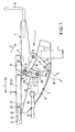
- the basic structure of the synchronous mechanism designated as a whole by 1 1 and 3 explained in more detail. Accordingly, it assigns a base holder 2, which by means of a cone holder 3 on the upper end of a Chair column 4 is set. Outside and above the side, parallel to the longitudinal direction L of the chair cheeks 5 are different Construction parts of the synchronous mechanism 1. These are the core pieces on the one hand an essentially frame-shaped seat support 6 and an in Top view of fork-shaped backrest support 7. On the seat support 6 is the seat with a padded seat (not shown) is mounted. The backrest support 7 holds via an angled cross member 18 a backrest, also not shown, in modern office chairs is adjustable in height.
- the backrest support 7 is thus articulated with a handlebar arrangement connected to the base support 2.
- This handlebar arrangement has a first Link 8, which is approximately in the middle of a pivot bearing 9 on the base support 2 is articulated.
- a second link 10 is between the front link 8 and Cone seat 3 mounted on a pivot bearing 11 on the base support 2.
- the free ends of the two links 8, 10 are connected via joints 12, 13 coupled to the backrest support 7.
- the two pivot bearings 9, 11 and the joints 12, 13 define a four-link chain in which the backrest support 7 itself with its respective fork leg 14 forms.
- the front link 8 is approximately vertically upwards, while the rear one Handlebar 10 is inclined to the rear.
- the two through the hinge points extending longitudinal axes 15, 16 of the links 8, 10 form one opening upwards towards the seat support 6, acute angle W (FIG. 1) of just over 30 °.
- the aspect ratio between the front and rear Handlebars 8, 10 is about 2.5: 3. Because of the above interpretation and arrangement of the four-link chain is carried out by the backrest support 7 the indicated in Fig. 1 by the arrow 17 superimposed rotary and Swiveling movement backwards and downwards.
- the seat support 6 is in front of its rear End 19 with the backrest support 7 via a bearing eye 20 to the front joint 12 forming axis coupled and so with its rear Articulated end area.
- the joint between seat support 6 and backrest support 7 is thus in the front joint 12 between the handlebar 8 and backrest support 7 integrated.
- At its front end region 21 - that is 1 in the left is the seat support 6 with the base support 2 over one as a whole connected with 22 designated rotary-slide joint.
- the latter is on a bearing extension 27 of the base support 2 is formed and is perpendicular to the central longitudinal plane M from this outwards and into the scenery 25.
- the synchronous mechanism 1 is countered by a spring arrangement F.
- Arrow direction 17 - that is, pretensioned to the basic position of the synchronous mechanism 1.
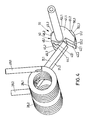
- This spring arrangement F is in the form of two in the transverse direction mutually aligned leg springs 28 (Fig. 3) given around the the pivot bearing 9 of the front link 8 forming axis 21 positioned are.
- the upward-pointing support leg 29 is supported on a projection 30 on the seat support 6, while the second, running forward Adjustment leg 31 is supported in an adjustment mechanism 32 in the base support 2.
- the leg springs 20 exert a spring force against the rear directed pivotal movement of the backrest by the Adjustment mechanism 32 can be varied by actuation by a rotary lever 33 is.
- the backrest support leads 7 when the backrest is loaded to the rear the swivel-rotary movement indicated by arrow 17 to the rear below, with the rear link 10 of the four-bar chain continuing to the rear and the front handlebar 8 also fold backwards.
- the Angle W between the longitudinal axes 15, 16 of the two links 8, 10 approximately 20 ° (Fig. 2).
- the four-link chain folds, so to speak the further spread starting position according to FIG. 1 together, so that this already compact arrangement is further reduced becomes.
- the compact arrangement also contributes to the fact that the distance a between the two Joints 12, 13 between the backrest support 7 and the handlebars 8 or 10 sit, approximately equal to the length L10 of the rear link 10 and in the ratio already given is greater than the length L8 of the front Handlebar 8 is.
- the seat support 6 Due to the mentioned pivoting movement of the four-link chain with the backrest support 7, the seat support 6 is both down towards the rear pivoted as well as horizontally in the region of the rotary sliding joint 22 moved backwards. This means that there is no relevant stroke movement of the front end 21 of the seat, causing any constrictions or avoid pressure on the underside of the thighs become.
- the synchronous mechanism 1 is otherwise designed so that in Fig. 2nd shown swung back end position of the backrest support 7 a Swivel angle W7 of approx. 26 ° passes during the swivel angle W6 of the seat support 6 is approximately 15 °.
- the ratio W7: W6 of the two Swivel angle is approximately 1.8: 1 at maximum swivel.
- the synchronizing mechanism 1 is in different Positions between the basic position (Fig. 1) and the maximum position pivoted to the rear (FIG. 2).
- the corresponding Locking device is not shown explicitly in the figures and is required it belongs to the state of the art - no detailed discussion. It it is only pointed out that the determination with the further Operating lever 35 on the side of the rotary lever 33. The one on the operating lever 36 on the other side is used to trigger the height adjustment the chair column 4.
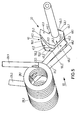
- the heart of the adjustment mechanism 32 is a one-piece double eccentric cam 40, which consists of a pair of axially adjacent eccentric cams 41.1, 41.2, each of which has one of the adjusting legs 31.1, 31.2 of the respective leg spring 28.1, 28.2 is supported.
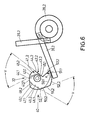
- the outwardly facing cam surfaces 42.1, 42.2 of the eccentric cam 41.1, 41.2 are related to the direction of eccentric rotation in successive Divided sections. So the solid in Fig. 6 begins Lines shown cam surface 42.2 of the eccentric cam 41.2 with a first, flat locking section 43.2, which is a coplanar, flat extension a first, radially outwardly rising cam control section 44.2 followed. The cam surface 42.2 then sits in a first holding section 45.2 continues, in which the cam surface is concentric to that of the shaft 46 formed axis of rotation of the double eccentric cam 40 over an angle of rotation of about 60 °.
- the cam surface 42.1 of the other eccentric cam 41.1 is shown in FIG a solid line thinner than the cam surface 42.2 shown since they are behind the eccentric cam in the direction of view according to FIG. 6 41.2 lies hidden.
- the latter goes in a second holding section 49.1, which in turn turns into a second Locking section 47.1 with coplanarly extended second cam control section 48.1 continues.
- third holding section 52.1 (again concentric to shaft 46), which is in a third locking section 50.1 and subsequent third cam control section 51.1 continues. This goes into a last short fourth rest section 53.1 about.
- the starting position is, for example, the lowest deflection position shown in FIG. 4 the adjusting leg 31.1, 31.2.
- the adjusting leg 31.2 In this rotary position of the double eccentric cam 40 is the adjusting leg 31.2 on the parallel to it first latching section 43.2 of the cam surface 42.2. From him Force K exerted on eccentric cams 41.2 extends radially in the direction to the eccentric axis of rotation (shaft 46), so that none of the adjusting leg 31.2 Force component exerted in the sense of a rotation of the shaft 46 becomes. Any twisting would only be due to a torque on the Shaft 46 are caused, whereby the position shown in Fig. 4 is quasi rasterized.
- the adjusting leg 31.1 of the other leg spring 28.1 lies in a point contact on the first holding section 45.1 of the cam surface 42.1 , which also means that there is no torque on the double eccentric cams 40 is exercised.
Landscapes
- Health & Medical Sciences (AREA)
- Dentistry (AREA)
- General Health & Medical Sciences (AREA)
- Chairs For Special Purposes, Such As Reclining Chairs (AREA)
- Chairs Characterized By Structure (AREA)
- Springs (AREA)
- Fluid-Damping Devices (AREA)
- Legs For Furniture In General (AREA)
Applications Claiming Priority (2)
| Application Number | Priority Date | Filing Date | Title |
|---|---|---|---|
| DE2001126001 DE10126001A1 (de) | 2001-05-18 | 2001-05-18 | Vorgespannte Federanordnung, insbesondere zur Federbeaufschlagung von Synchronmechaniken von Bürostühlen |
| DE10126001 | 2001-05-18 |
Publications (3)
| Publication Number | Publication Date |
|---|---|
| EP1258208A2 true EP1258208A2 (fr) | 2002-11-20 |
| EP1258208A3 EP1258208A3 (fr) | 2004-01-28 |
| EP1258208B1 EP1258208B1 (fr) | 2006-03-22 |
Family
ID=7686436
Family Applications (1)
| Application Number | Title | Priority Date | Filing Date |
|---|---|---|---|
| EP20020009188 Expired - Lifetime EP1258208B1 (fr) | 2001-05-18 | 2002-04-25 | Ressort précontraint, notamment pour mécanismes synchronisés dans chaises de bureau |
Country Status (4)
| Country | Link |
|---|---|
| US (1) | US6709056B2 (fr) |
| EP (1) | EP1258208B1 (fr) |
| AT (1) | ATE320736T1 (fr) |
| DE (2) | DE10126001A1 (fr) |
Cited By (5)
| Publication number | Priority date | Publication date | Assignee | Title |
|---|---|---|---|---|
| EP1985206A1 (fr) * | 2006-02-15 | 2008-10-29 | Vicente Berbegal Perez | Fauteuil de bureau |
| WO2009127862A1 (fr) * | 2008-04-17 | 2009-10-22 | Simclar Seating Technologies Limited | Dispositif permettant d'opposer une tension à l'inclinaison d'un dossier de siège |
| WO2012048863A1 (fr) * | 2010-10-15 | 2012-04-19 | Bock 1 Gmbh & Co. Kg | Mécanisme synchrone |
| WO2016124317A1 (fr) * | 2015-02-03 | 2016-08-11 | Bock 1 Gmbh & Co. Kg | Mecanisme synchrone |
| US20180289159A1 (en) * | 2017-04-10 | 2018-10-11 | Bock 1 Gmbh & Co. Kg | Synchronized mechanism for an office chair |
Families Citing this family (37)
| Publication number | Priority date | Publication date | Assignee | Title |
|---|---|---|---|---|
| EP1527714B1 (fr) * | 2002-07-23 | 2008-11-26 | Okamura corporation | Chaise |
| US6880886B2 (en) * | 2002-09-12 | 2005-04-19 | Steelcase Development Corporation | Combined tension and back stop function for seating unit |
| ITTO20030152A1 (it) * | 2003-03-04 | 2004-09-05 | Pro Cord Spa | Sedia con sedile oscillante. |
| US6793284B1 (en) * | 2003-03-19 | 2004-09-21 | L & P Property Management Company | Steel spring with dwell for chairs |
| US7048335B2 (en) * | 2003-06-05 | 2006-05-23 | Steelcase Development Corporation | Seating unit with crossbar seat support |
| US6957862B2 (en) * | 2003-10-09 | 2005-10-25 | Su-Ming Chen | Chair with a seat-inclination adjusting device |
| US6969116B2 (en) | 2003-12-30 | 2005-11-29 | Hni Technologies Inc. | Chair with backward and forward passive tilt capabilities |
| US7147285B2 (en) * | 2004-01-20 | 2006-12-12 | Tung Yu Oa Co., Ltd. | Reclining apparatus for chair |
| US7878595B2 (en) * | 2005-01-04 | 2011-02-01 | Toyota Boshoku Kabushiki Kaisha | Pivot mechanism |
| ES2527757T3 (es) * | 2005-03-01 | 2015-01-29 | Haworth, Inc. | Mecanismo de regulación de tensión |
| DE202005006980U1 (de) * | 2005-04-28 | 2006-09-07 | Bock 1 Gmbh & Co. Kg | Sitzmöbel, insbesondere Bürostuhl |
| EP1938713B1 (fr) * | 2005-10-18 | 2014-02-26 | Delta Tooling Co., Ltd. | Structure de siège |
| CA2646948A1 (fr) * | 2006-03-24 | 2007-10-04 | Herman Miller Inc. | Meuble |
| GB0609315D0 (en) * | 2006-05-11 | 2006-06-21 | Technicon Internat Man Service | Improved seat |
| KR200431307Y1 (ko) * | 2006-08-22 | 2006-11-23 | 한일정공(주) | 운동의자의 록킹장치 |
| DE202007006762U1 (de) * | 2006-10-13 | 2008-02-14 | Bock 1 Gmbh & Co. Kg | Mechanik für einen Bürostuhl |
| ITTO20070398A1 (it) * | 2007-06-06 | 2008-12-07 | Malenotti S R L | "sedia con schienale oscillante" |
| JP5490004B2 (ja) * | 2007-09-20 | 2014-05-14 | ハーマン、ミラー、インコーポレイテッド | 身体支持構造 |
| US8170261B2 (en) * | 2008-02-20 | 2012-05-01 | Logitech Europe S.A. | Personal audio set with adjustable force mechanisms |
| DE102009009287A1 (de) * | 2009-02-17 | 2010-09-09 | Uhlenbrock, Christel | Sitzmöbel, insbesondere Bürodrehstuhl |
| EP2298132B1 (fr) * | 2009-09-16 | 2018-06-13 | Haworth GmbH | Siège, notamment siège de bureau |
| JP5514509B2 (ja) * | 2009-10-26 | 2014-06-04 | 株式会社イトーキ | ロッキング椅子 |
| EP2347676B1 (fr) * | 2010-01-22 | 2012-08-22 | Stoll Giroflex AG | Structure porteuse pour un élément de dossier et/ou un siège d'un dispositif d'assise et dispositif d'assise doté d'une telle structure porteuse |
| US8714645B2 (en) * | 2010-01-28 | 2014-05-06 | Sava Cvek | Pivoting mechanism with gross and fine resistance adjustment |
| US8714646B2 (en) | 2010-02-08 | 2014-05-06 | Sava Cvek | Mobile task chair and mobile task chair control mechanism with adjustment capabilities and visual setting indicators |
| KR101533650B1 (ko) * | 2010-04-15 | 2015-07-03 | 주식회사 시디즈 | 의자의 등받이에 작용하는 복원력을 조정하기 위한 조정 메커니즘 및 상기 조정 메커니즘을 구비한 사무용 의자 |
| GB201014953D0 (en) * | 2010-09-08 | 2010-10-20 | Birkbeck Hilary R | Slide chair action |
| US9215934B2 (en) * | 2011-10-21 | 2015-12-22 | Jae Hyun Lee | Corrective chair using slider means |
| DE202012002288U1 (de) * | 2012-03-08 | 2012-05-11 | Walter Knoll Ag & Co. Kg | Funktionsstuhl |
| USD697726S1 (en) | 2012-09-20 | 2014-01-21 | Steelcase Inc. | Chair |
| US11304528B2 (en) | 2012-09-20 | 2022-04-19 | Steelcase Inc. | Chair assembly with upholstery covering |
| CN103876498B (zh) * | 2014-03-26 | 2016-08-24 | 汕头市丽时家具有限公司 | 座椅底盘和具有该座椅底盘的座椅 |
| WO2015161281A1 (fr) * | 2014-04-17 | 2015-10-22 | Hni Technologies Inc. | Chaise et ensembles, systèmes et procédés de commande de chaise |
| CA2978966A1 (fr) * | 2015-03-10 | 2016-09-15 | Hans Johann WABL | Moyen de reglage pour chaise |
| US10463153B2 (en) * | 2016-06-09 | 2019-11-05 | Steelcase Inc. | Seating arrangement |
| US11071386B2 (en) | 2016-06-09 | 2021-07-27 | Sava Cvek | Seat pivoting mechanism and chair height locking system |
| DE102020101033A1 (de) | 2020-01-17 | 2021-07-22 | Bock 1 Gmbh & Co. Kg | Träger für ein Sitzmöbel |
Citations (2)
| Publication number | Priority date | Publication date | Assignee | Title |
|---|---|---|---|---|
| DE19810768A1 (de) | 1998-03-06 | 1999-09-09 | Drabert Gmbh | Bürostuhl mit Synchronmechanik |
| DE19922446A1 (de) | 1999-05-07 | 2000-11-09 | Bock 1 Gmbh & Co | Synchronmechanik für eine korrelierte Sitz-Rückenlehnen-Bewegung eines Bürostühles |
Family Cites Families (30)
| Publication number | Priority date | Publication date | Assignee | Title |
|---|---|---|---|---|
| US308424A (en) * | 1884-11-25 | gaednee mobey | ||
| US453254A (en) * | 1891-06-02 | Dental drill | ||
| US3339973A (en) * | 1966-01-05 | 1967-09-05 | Doerner Products Co Ltd | Torsion spring chair control |
| US3832779A (en) * | 1973-02-09 | 1974-09-03 | M Reynaud | Device for milling and taking impression for the placing of peg teeth |
| US4187611A (en) * | 1977-10-07 | 1980-02-12 | University Of Iowa Research Foundation | Dental retention pin and method |
| US4345899A (en) * | 1979-07-12 | 1982-08-24 | Vlock D G | Dental twist drill |
| US4588175A (en) * | 1982-09-29 | 1986-05-13 | Martin Door Manufacturing | Torsion spring apparatus and method |
| US4611508A (en) * | 1983-02-08 | 1986-09-16 | Roane James B | Endodontic instrument |
| US4536159A (en) * | 1983-02-08 | 1985-08-20 | Roane James B | Endodontic instrument |
| US4443193A (en) * | 1983-02-08 | 1984-04-17 | Roane James B | Endodontic instrument |
| CA1184108A (fr) * | 1984-04-09 | 1985-03-19 | David W. Smith | Suspension de fauteuil basculant |
| US4661061A (en) * | 1985-07-22 | 1987-04-28 | Howard Martin | Four sided root canal rasp for root canal preparation |
| DE8627482U1 (fr) * | 1986-10-15 | 1989-07-06 | Voelkle, Rolf, 7298 Lossburg, De | |
| US4923181A (en) * | 1987-08-18 | 1990-05-08 | Street Specialty Products Inc. | Springs for a corvette rear-seat storage compartment cover opener |
| SE457230B (sv) * | 1987-11-13 | 1988-12-12 | Eva Margareta Axelsson Stenstr | Odontologiskt instrument foer rengoering och avplaning av tandrotsytor |
| US4934934A (en) * | 1988-11-04 | 1990-06-19 | Quality Dental Products, Inc. | Dental file/reamer instrument |
| JPH04502870A (ja) * | 1988-11-18 | 1992-05-28 | ウェイスマン,ベルナルド | 湾曲した歯管に追従自在な歯科用リーマ |
| US5224758A (en) * | 1989-12-27 | 1993-07-06 | Itoki Crebio Corporation | Tilting control assembly for chair |
| US5029940A (en) * | 1990-01-16 | 1991-07-09 | Westinghouse Electric Corporation | Chair tilt and chair height control apparatus |
| US5215461A (en) * | 1991-03-22 | 1993-06-01 | John Riazi | Endodontic appliance and related method |
| JP3330145B2 (ja) * | 1991-05-21 | 2002-09-30 | 株式会社イトーキ | 椅子の背,座部の連動支持機構 |
| US5318346A (en) * | 1991-05-30 | 1994-06-07 | Steelcase Inc. | Chair with zero front rise control |
| DE4135948C2 (de) * | 1991-10-31 | 1993-12-23 | Rolf Voelkle | Stuhl, insbesondere Bürodrehstuhl |
| US5527205A (en) * | 1991-11-05 | 1996-06-18 | Tulsa Dental Products, L.L.C. | Method of fabricating an endodontic instrument |
| DE4411471C2 (de) * | 1994-04-01 | 1998-07-02 | Daimler Benz Ag | Klappbare Haltevorrichtung für Kopfstütze |
| AU2954695A (en) * | 1994-06-10 | 1996-01-05 | Haworth Inc. | Ergonomic chair |
| US5810439A (en) * | 1996-05-09 | 1998-09-22 | Haworth, Inc. | Forward-rearward tilt control for chair |
| US6059363A (en) * | 1997-04-30 | 2000-05-09 | Haworth, Inc. | Chairback with side torsional movement |
| DE10026292C2 (de) * | 1999-07-06 | 2003-03-20 | Roeder Peter | Stuhl |
| US6186788B1 (en) * | 1999-08-26 | 2001-02-13 | Massad Enterprises, Inc. | Lingual occlusal bur |
-
2001
- 2001-05-18 DE DE2001126001 patent/DE10126001A1/de not_active Withdrawn
-
2002
- 2002-04-25 EP EP20020009188 patent/EP1258208B1/fr not_active Expired - Lifetime
- 2002-04-25 DE DE50206108T patent/DE50206108D1/de not_active Expired - Fee Related
- 2002-04-25 AT AT02009188T patent/ATE320736T1/de not_active IP Right Cessation
- 2002-05-20 US US10/147,856 patent/US6709056B2/en not_active Expired - Fee Related
Patent Citations (2)
| Publication number | Priority date | Publication date | Assignee | Title |
|---|---|---|---|---|
| DE19810768A1 (de) | 1998-03-06 | 1999-09-09 | Drabert Gmbh | Bürostuhl mit Synchronmechanik |
| DE19922446A1 (de) | 1999-05-07 | 2000-11-09 | Bock 1 Gmbh & Co | Synchronmechanik für eine korrelierte Sitz-Rückenlehnen-Bewegung eines Bürostühles |
Cited By (7)
| Publication number | Priority date | Publication date | Assignee | Title |
|---|---|---|---|---|
| EP1985206A1 (fr) * | 2006-02-15 | 2008-10-29 | Vicente Berbegal Perez | Fauteuil de bureau |
| EP1985206A4 (fr) * | 2006-02-15 | 2012-10-31 | Perez Vicente Berbegal | Fauteuil de bureau |
| WO2009127862A1 (fr) * | 2008-04-17 | 2009-10-22 | Simclar Seating Technologies Limited | Dispositif permettant d'opposer une tension à l'inclinaison d'un dossier de siège |
| WO2012048863A1 (fr) * | 2010-10-15 | 2012-04-19 | Bock 1 Gmbh & Co. Kg | Mécanisme synchrone |
| WO2016124317A1 (fr) * | 2015-02-03 | 2016-08-11 | Bock 1 Gmbh & Co. Kg | Mecanisme synchrone |
| US20180289159A1 (en) * | 2017-04-10 | 2018-10-11 | Bock 1 Gmbh & Co. Kg | Synchronized mechanism for an office chair |
| US10610019B2 (en) * | 2017-04-10 | 2020-04-07 | Bock 1 Gmbh & Co. Kg | Synchronized mechanism for an office chair |
Also Published As
| Publication number | Publication date |
|---|---|
| EP1258208A3 (fr) | 2004-01-28 |
| DE10126001A1 (de) | 2002-11-21 |
| DE50206108D1 (de) | 2006-05-11 |
| EP1258208B1 (fr) | 2006-03-22 |
| US6709056B2 (en) | 2004-03-23 |
| ATE320736T1 (de) | 2006-04-15 |
| US20020171277A1 (en) | 2002-11-21 |
Similar Documents
| Publication | Publication Date | Title |
|---|---|---|
| EP1258208B1 (fr) | Ressort précontraint, notamment pour mécanismes synchronisés dans chaises de bureau | |
| DE3704083C2 (de) | Funktions-Sitzmöbel | |
| EP1258210B1 (fr) | Mécanisme synchronisé pour un mouvement correlé entre une siège et un dossier d'une chaise de bureau | |
| DE2525752C2 (de) | Höhenverstellbarer Stuhl mit Neigungsänderung von Lehne oder Sitzfläche | |
| DE1778196C3 (de) | Hubvorrichtung für ein Sitzmöbel | |
| EP3583867B1 (fr) | Chaise | |
| DE19646470A1 (de) | Kraftfahrzeugsitz mit einer Lehne und einem Sitz | |
| EP1850699B1 (fr) | Meuble, en particulier meuble d'assise | |
| EP1396213A1 (fr) | Mécanisme synchronisé pour chaises de bureau | |
| DE19644087B4 (de) | Lehnenbeschlag für einen Kraftfahrzeugsitz | |
| DE112011103438T5 (de) | Fahrzeugsitz | |
| WO2011141107A1 (fr) | Mécanisme de réglage d'une force de rappel agissant sur le dossier d'un siège et siège de bureau doté d'un mécanisme de ce type | |
| DE3910143C2 (de) | Kraftfahrzeugsitz mit einer mit Seitenstützen versehenen Rückenlehne | |
| EP3120732B1 (fr) | Mecanisme de siege de bureau | |
| EP1291232B1 (fr) | Châssis de siège de véhicules automobiles avec un support de siège et bras avant de parallélogramme | |
| DE3618705C2 (de) | Funktions-Sitzmöbel | |
| DE7630781U1 (de) | Stuhl, sessel oder dergleichen sitzmoebel | |
| DE202011110645U1 (de) | Tisch | |
| EP3528664B1 (fr) | Dispositif de mécanisme synchrone et chaise en étant équipée | |
| DE202020104509U1 (de) | Sitz- und Liegemöbel | |
| AT401462B (de) | Sitz- bzw. liegemöbel | |
| DE1159147B (de) | Hebelsteuereinrichtung fuer die Beinstuetze eines Verstellsessels | |
| EP0341344A2 (fr) | Meuble servant de siège | |
| EP0087498A2 (fr) | Table à plateau réglable | |
| DE3202848C1 (de) | Fußstütze |
Legal Events
| Date | Code | Title | Description |
|---|---|---|---|
| PUAI | Public reference made under article 153(3) epc to a published international application that has entered the european phase |
Free format text: ORIGINAL CODE: 0009012 |
|
| AK | Designated contracting states |
Kind code of ref document: A2 Designated state(s): AT BE CH CY DE DK ES FI FR GB GR IE IT LI LU MC NL PT SE TR |
|
| AX | Request for extension of the european patent |
Free format text: AL;LT;LV;MK;RO;SI |
|
| PUAL | Search report despatched |
Free format text: ORIGINAL CODE: 0009013 |
|
| AK | Designated contracting states |
Kind code of ref document: A3 Designated state(s): AT BE CH CY DE DK ES FI FR GB GR IE IT LI LU MC NL PT SE TR |
|
| AX | Request for extension of the european patent |
Extension state: AL LT LV MK RO SI |
|
| RIC1 | Information provided on ipc code assigned before grant |
Ipc: 7A 47C 1/032 B Ipc: 7A 47C 1/024 A |
|
| 17P | Request for examination filed |
Effective date: 20040526 |
|
| AKX | Designation fees paid |
Designated state(s): AT BE CH CY DE DK ES FI FR GB GR IE IT LI LU MC NL PT SE TR |
|
| GRAP | Despatch of communication of intention to grant a patent |
Free format text: ORIGINAL CODE: EPIDOSNIGR1 |
|
| GRAS | Grant fee paid |
Free format text: ORIGINAL CODE: EPIDOSNIGR3 |
|
| GRAA | (expected) grant |
Free format text: ORIGINAL CODE: 0009210 |
|
| AK | Designated contracting states |
Kind code of ref document: B1 Designated state(s): AT BE CH CY DE DK ES FI FR GB GR IE IT LI LU MC NL PT SE TR |
|
| PG25 | Lapsed in a contracting state [announced via postgrant information from national office to epo] |
Ref country code: IT Free format text: LAPSE BECAUSE OF FAILURE TO SUBMIT A TRANSLATION OF THE DESCRIPTION OR TO PAY THE FEE WITHIN THE PRESCRIBED TIME-LIMIT;WARNING: LAPSES OF ITALIAN PATENTS WITH EFFECTIVE DATE BEFORE 2007 MAY HAVE OCCURRED AT ANY TIME BEFORE 2007. THE CORRECT EFFECTIVE DATE MAY BE DIFFERENT FROM THE ONE RECORDED. Effective date: 20060322 Ref country code: IE Free format text: LAPSE BECAUSE OF FAILURE TO SUBMIT A TRANSLATION OF THE DESCRIPTION OR TO PAY THE FEE WITHIN THE PRESCRIBED TIME-LIMIT Effective date: 20060322 |
|
| REG | Reference to a national code |
Ref country code: GB Ref legal event code: FG4D Free format text: NOT ENGLISH |
|
| REG | Reference to a national code |
Ref country code: CH Ref legal event code: EP |
|
| GBT | Gb: translation of ep patent filed (gb section 77(6)(a)/1977) |
Effective date: 20060322 |
|
| PGFP | Annual fee paid to national office [announced via postgrant information from national office to epo] |
Ref country code: NL Payment date: 20060419 Year of fee payment: 5 |
|
| REG | Reference to a national code |
Ref country code: IE Ref legal event code: FG4D Free format text: LANGUAGE OF EP DOCUMENT: GERMAN |
|
| PGFP | Annual fee paid to national office [announced via postgrant information from national office to epo] |
Ref country code: FR Payment date: 20060420 Year of fee payment: 5 |
|
| PG25 | Lapsed in a contracting state [announced via postgrant information from national office to epo] |
Ref country code: AT Free format text: LAPSE BECAUSE OF NON-PAYMENT OF DUE FEES Effective date: 20060425 |
|
| PGFP | Annual fee paid to national office [announced via postgrant information from national office to epo] |
Ref country code: GB Payment date: 20060426 Year of fee payment: 5 |
|
| PG25 | Lapsed in a contracting state [announced via postgrant information from national office to epo] |
Ref country code: CH Free format text: LAPSE BECAUSE OF NON-PAYMENT OF DUE FEES Effective date: 20060430 Ref country code: BE Free format text: LAPSE BECAUSE OF NON-PAYMENT OF DUE FEES Effective date: 20060430 Ref country code: MC Free format text: LAPSE BECAUSE OF NON-PAYMENT OF DUE FEES Effective date: 20060430 Ref country code: LI Free format text: LAPSE BECAUSE OF NON-PAYMENT OF DUE FEES Effective date: 20060430 |
|
| REF | Corresponds to: |
Ref document number: 50206108 Country of ref document: DE Date of ref document: 20060511 Kind code of ref document: P |
|
| PGFP | Annual fee paid to national office [announced via postgrant information from national office to epo] |
Ref country code: DE Payment date: 20060620 Year of fee payment: 5 |
|
| PG25 | Lapsed in a contracting state [announced via postgrant information from national office to epo] |
Ref country code: SE Free format text: LAPSE BECAUSE OF FAILURE TO SUBMIT A TRANSLATION OF THE DESCRIPTION OR TO PAY THE FEE WITHIN THE PRESCRIBED TIME-LIMIT Effective date: 20060622 Ref country code: DK Free format text: LAPSE BECAUSE OF FAILURE TO SUBMIT A TRANSLATION OF THE DESCRIPTION OR TO PAY THE FEE WITHIN THE PRESCRIBED TIME-LIMIT Effective date: 20060622 |
|
| PG25 | Lapsed in a contracting state [announced via postgrant information from national office to epo] |
Ref country code: ES Free format text: LAPSE BECAUSE OF FAILURE TO SUBMIT A TRANSLATION OF THE DESCRIPTION OR TO PAY THE FEE WITHIN THE PRESCRIBED TIME-LIMIT Effective date: 20060703 |
|
| PG25 | Lapsed in a contracting state [announced via postgrant information from national office to epo] |
Ref country code: PT Free format text: LAPSE BECAUSE OF FAILURE TO SUBMIT A TRANSLATION OF THE DESCRIPTION OR TO PAY THE FEE WITHIN THE PRESCRIBED TIME-LIMIT Effective date: 20060822 |
|
| ET | Fr: translation filed | ||
| REG | Reference to a national code |
Ref country code: IE Ref legal event code: FD4D |
|
| REG | Reference to a national code |
Ref country code: CH Ref legal event code: PL |
|
| PLBE | No opposition filed within time limit |
Free format text: ORIGINAL CODE: 0009261 |
|
| STAA | Information on the status of an ep patent application or granted ep patent |
Free format text: STATUS: NO OPPOSITION FILED WITHIN TIME LIMIT |
|
| 26N | No opposition filed |
Effective date: 20061227 |
|
| GBPC | Gb: european patent ceased through non-payment of renewal fee |
Effective date: 20070425 |
|
| BERE | Be: lapsed |
Owner name: BOCK-1 G.M.B.H. & CO. Effective date: 20060430 |
|
| NLV4 | Nl: lapsed or anulled due to non-payment of the annual fee |
Effective date: 20071101 |
|
| PG25 | Lapsed in a contracting state [announced via postgrant information from national office to epo] |
Ref country code: DE Free format text: LAPSE BECAUSE OF NON-PAYMENT OF DUE FEES Effective date: 20071101 Ref country code: NL Free format text: LAPSE BECAUSE OF NON-PAYMENT OF DUE FEES Effective date: 20071101 |
|
| PG25 | Lapsed in a contracting state [announced via postgrant information from national office to epo] |
Ref country code: GR Free format text: LAPSE BECAUSE OF FAILURE TO SUBMIT A TRANSLATION OF THE DESCRIPTION OR TO PAY THE FEE WITHIN THE PRESCRIBED TIME-LIMIT Effective date: 20060623 Ref country code: GB Free format text: LAPSE BECAUSE OF NON-PAYMENT OF DUE FEES Effective date: 20070425 |
|
| PG25 | Lapsed in a contracting state [announced via postgrant information from national office to epo] |
Ref country code: FI Free format text: LAPSE BECAUSE OF FAILURE TO SUBMIT A TRANSLATION OF THE DESCRIPTION OR TO PAY THE FEE WITHIN THE PRESCRIBED TIME-LIMIT Effective date: 20060322 |
|
| PG25 | Lapsed in a contracting state [announced via postgrant information from national office to epo] |
Ref country code: TR Free format text: LAPSE BECAUSE OF FAILURE TO SUBMIT A TRANSLATION OF THE DESCRIPTION OR TO PAY THE FEE WITHIN THE PRESCRIBED TIME-LIMIT Effective date: 20060322 Ref country code: FR Free format text: LAPSE BECAUSE OF NON-PAYMENT OF DUE FEES Effective date: 20070430 Ref country code: LU Free format text: LAPSE BECAUSE OF NON-PAYMENT OF DUE FEES Effective date: 20060425 |
|
| PG25 | Lapsed in a contracting state [announced via postgrant information from national office to epo] |
Ref country code: CY Free format text: LAPSE BECAUSE OF FAILURE TO SUBMIT A TRANSLATION OF THE DESCRIPTION OR TO PAY THE FEE WITHIN THE PRESCRIBED TIME-LIMIT Effective date: 20060322 |