EP2347676B1 - Structure porteuse pour un élément de dossier et/ou un siège d'un dispositif d'assise et dispositif d'assise doté d'une telle structure porteuse - Google Patents
Structure porteuse pour un élément de dossier et/ou un siège d'un dispositif d'assise et dispositif d'assise doté d'une telle structure porteuse Download PDFInfo
- Publication number
- EP2347676B1 EP2347676B1 EP10405014A EP10405014A EP2347676B1 EP 2347676 B1 EP2347676 B1 EP 2347676B1 EP 10405014 A EP10405014 A EP 10405014A EP 10405014 A EP10405014 A EP 10405014A EP 2347676 B1 EP2347676 B1 EP 2347676B1
- Authority
- EP
- European Patent Office
- Prior art keywords
- spring element
- outer housing
- inner housing
- support
- rotation
- Prior art date
- Legal status (The legal status is an assumption and is not a legal conclusion. Google has not performed a legal analysis and makes no representation as to the accuracy of the status listed.)
- Not-in-force
Links
Images


Classifications
-
- A—HUMAN NECESSITIES
- A47—FURNITURE; DOMESTIC ARTICLES OR APPLIANCES; COFFEE MILLS; SPICE MILLS; SUCTION CLEANERS IN GENERAL
- A47C—CHAIRS; SOFAS; BEDS
- A47C1/00—Chairs adapted for special purposes
- A47C1/02—Reclining or easy chairs
- A47C1/031—Reclining or easy chairs having coupled concurrently adjustable supporting parts
- A47C1/032—Reclining or easy chairs having coupled concurrently adjustable supporting parts the parts being movably-coupled seat and back-rest
- A47C1/03255—Reclining or easy chairs having coupled concurrently adjustable supporting parts the parts being movably-coupled seat and back-rest with a central column, e.g. rocking office chairs
-
- A—HUMAN NECESSITIES
- A47—FURNITURE; DOMESTIC ARTICLES OR APPLIANCES; COFFEE MILLS; SPICE MILLS; SUCTION CLEANERS IN GENERAL
- A47C—CHAIRS; SOFAS; BEDS
- A47C1/00—Chairs adapted for special purposes
- A47C1/02—Reclining or easy chairs
- A47C1/031—Reclining or easy chairs having coupled concurrently adjustable supporting parts
- A47C1/032—Reclining or easy chairs having coupled concurrently adjustable supporting parts the parts being movably-coupled seat and back-rest
- A47C1/03261—Reclining or easy chairs having coupled concurrently adjustable supporting parts the parts being movably-coupled seat and back-rest characterised by elastic means
- A47C1/03266—Reclining or easy chairs having coupled concurrently adjustable supporting parts the parts being movably-coupled seat and back-rest characterised by elastic means with adjustable elasticity
-
- A—HUMAN NECESSITIES
- A47—FURNITURE; DOMESTIC ARTICLES OR APPLIANCES; COFFEE MILLS; SPICE MILLS; SUCTION CLEANERS IN GENERAL
- A47C—CHAIRS; SOFAS; BEDS
- A47C1/00—Chairs adapted for special purposes
- A47C1/02—Reclining or easy chairs
- A47C1/031—Reclining or easy chairs having coupled concurrently adjustable supporting parts
- A47C1/032—Reclining or easy chairs having coupled concurrently adjustable supporting parts the parts being movably-coupled seat and back-rest
- A47C1/03261—Reclining or easy chairs having coupled concurrently adjustable supporting parts the parts being movably-coupled seat and back-rest characterised by elastic means
- A47C1/03277—Reclining or easy chairs having coupled concurrently adjustable supporting parts the parts being movably-coupled seat and back-rest characterised by elastic means with bar or leaf springs
-
- A—HUMAN NECESSITIES
- A47—FURNITURE; DOMESTIC ARTICLES OR APPLIANCES; COFFEE MILLS; SPICE MILLS; SUCTION CLEANERS IN GENERAL
- A47C—CHAIRS; SOFAS; BEDS
- A47C1/00—Chairs adapted for special purposes
- A47C1/02—Reclining or easy chairs
- A47C1/031—Reclining or easy chairs having coupled concurrently adjustable supporting parts
- A47C1/032—Reclining or easy chairs having coupled concurrently adjustable supporting parts the parts being movably-coupled seat and back-rest
- A47C1/03261—Reclining or easy chairs having coupled concurrently adjustable supporting parts the parts being movably-coupled seat and back-rest characterised by elastic means
- A47C1/03288—Reclining or easy chairs having coupled concurrently adjustable supporting parts the parts being movably-coupled seat and back-rest characterised by elastic means with resilient blocks
Definitions
- the invention relates to a support structure for a back part and / or a seat of a seat device and a seat device with such a support structure.
- a support structure is off WO 98/4867 known.
- Seat devices such as chairs, are usually modular: They usually include next to a seat and possibly a back part, which may for example comprise a backrest, also a support structure for the respective back and / or and the respective seat, wherein it is the task of Trag Vietnamese is to hold the seat and possibly the back part in a certain position and a load, which can be transmitted, for example, from a person sitting on the seat on the seat or the back, and the seat and possibly the back part under the action of each load to be kept in a stable position.
- a back part which may for example comprise a backrest, also a support structure for the respective back and / or and the respective seat, wherein it is the task of Trag Decor is to hold the seat and possibly the back part in a certain position and a load, which can be transmitted, for example, from a person sitting on the seat on the seat or the back, and the seat and possibly the back part under the action of each load to be kept in a stable position.
- a conventional support structure of a seat device usually comprises a base support, which can be placed, for example, stationary in space, and at least one arranged on the base support member, which support member is fixed to the base support such that movement of the support member relative to the base support executable , And which support part is intended to hold the back part and / or the seat in a position which is dependent on the relative position of the support member relative to the base support.
- the back part or the seat does not have to be fastened directly to the carrier part: the back part or the seat can each be connected via one or more other components to said carrier part or coupled to the carrier part.
- a support structure of the aforementioned type can also be equipped with a force system for generating at least one restoring force, which is generated during the respective movement of the support part and directed counter to this movement.
- a power system may comprise one or more spring elements, which are respectively coupled to the base support and the support member, that the spring element generates a restoring force during the respective movement of the support member, which is opposite to the respective movement of the support member.
- Such a force system ensures a resilient arrangement of the back part or the seat, such that the respective back part and / or the respective seat are optionally deflected upon application of force from a predetermined equilibrium position, at the same time the support member deflected from a predetermined equilibrium position and one of Deflection of the support member counteracting restoring force is generated.
- the respective restoring force is included as a rule, the greater the further the support part is deflected out of the original equilibrium position.
- the force system generates a restoring force, which is opposite to the respective movement of the support member, the support member can then assume a new equilibrium position as soon as all forces acting on the support member compensate each other.
- the back part or the seat can each be held in an equilibrium position, which depends on the respective load of the back part or the seat.
- the latter ensures a high level of comfort, especially since the back and / or the seat can each adapt to the current posture of a seated person sitting on the seat and each restoring force generated by the force system each supporting the seated person acts.
- such a force system can be designed such that the magnitude of the restoring force, which generates the force system at a certain deflection of the support member from a predetermined equilibrium position, within a certain scope is variable and can be adjusted as needed. The latter allows an adaptation of the power system to different needs.
- adjustment of the force system is usually appropriate, for example, in which the force system generates a relatively large restoring force for a given deflection of the carrier part ("hard” setting of the force system), while in the case of small or light persons Rather, an adjustment of the power system is appropriate, in which the force system at a given deflection of the support member generates a relatively small restoring force ("soft" setting of the power system).
- a seat device which comprises a variable force system of the aforementioned type.
- This seat device a chair, has a supporting structure in connection with a power system of the aforementioned type.
- the power system comprises an elastomer torsion spring element which serves to generate a restoring torque, which counteracts a pivotal movement of a support for a seat (hereinafter referred to as "seat support") about an axis of rotation.
- the elastomer torsion spring element includes an inner housing and an outer housing, wherein in an intermediate space between the inner housing and the outer housing, an elastomeric body is introduced.
- the inner housing has on its outer side a contact surface on which the elastomeric body is in contact with the inner housing
- the outer housing has on its inner side a contact surface on which the elastomeric body is in contact with the outer housing.
- the elastomeric body with the respective contact surface of the inner housing and the respective contact surface of the outer housing is firmly connected, so that the elastomeric body can not slip either on the contact surface of the inner housing or on the contact surface of the outer housing relative to the inner housing or to the outer housing.
- the outer housing and the inner housing are cylindrical in the present case and aligned coaxially with each other.
- the outer housing is held on a supporting structure of the chair, while the inner housing rotatably seated on a shaft which is rotatable about its longitudinal axis.
- a seat of the chair is coupled to the shaft so that, if the seat is loaded by the weight of a person, the shaft is rotated about its longitudinal axis and the seat is pivoted from a predetermined home position.
- the inner housing is rotated about its longitudinal direction and thereby rotated relative to the outer housing, with the result that the elastomer torsion spring element on the Shaft or the seat acting restoring torque generated, which counteracts the rotational movement of the shaft or the pivotal movement of the seat and is larger with increasing angle of rotation.
- the outer housing can be rotated about its longitudinal axis by means of a rotating mechanism disposed on the support structure of the chair and thus rotated about the longitudinal axis of the shaft, the outer housing being rotated relative to the support structure of the chair and relative to the inner housing or shaft.
- the elastomer torsion spring element is biased, wherein the angle of rotation by which the outer housing is rotated relative to the inner housing, when the seat is in the home position determines the size of the "minimum return torque".
- the power system of the aforementioned seat device has various disadvantages.
- Said elastomer torsion spring element has the disadvantage that the restoring torque, which is generated upon rotation of said shaft by a certain angle of rotation, shows a relatively small increase as a function of the respective angle of rotation, in particular if the elastomer torsion spring element not or only slightly is biased. Consequently, the outer housing of the elastomer torsion spring element must be rotated by a relatively large angle of rotation relative to the inner housing and the elastomeric body of the elastomer torsion spring element are relatively strongly biased when a large minimum restoring torque is to be adjusted, for example, persons with high weight adequate seating comfort to be able to offer.
- the restoring torque generated by the elastomeric torsion spring member greatly increases nonlinearly (progressively) as a function of the rotational angle of the shaft when the shaft is to be rotated, for example, by a rotation angle in the range of 0 to about 70 °.
- the present invention is therefore based on the object to avoid the disadvantages mentioned and to provide a support structure or a seat device with a force system, which makes it possible to easily and conveniently change the restoring force generated by the power system over the largest possible area, for example, the power system can be easily and conveniently adapted to the needs of different people with large differences in body weight.
- a support structure for a back part and / or a seat of a seat device with the features of claim 1 and by a seat device which comprises this support structure.
- the support structure comprises a base support, at least one support part arranged on the base support for supporting and / or holding the respective back part and / or the respective seat, which support part is attached to the base support such that a movement of the support part relative to the base support is executable, and a force system for generating at least one restoring force, which is generated during the respective movement of the carrier part and is directed counter to this movement.
- the power system comprises at least one first spring element, which is coupled to the base carrier and the carrier part such that the first spring element generates a first restoring force during the respective movement of the carrier part, which is opposite to the respective movement of the carrier part.
- the carrier part is designed to hold the respective back part and / or the respective seat of the respective seat device in a position which is dependent on the relative position of the carrier part with respect to the base carrier.
- the back part or the seat does not have to be fastened directly to the carrier part: the back part or the seat can each be connected via one or more other components to said carrier part or coupled to the carrier part.
- the force system of the inventive support structure comprises different groups of spring elements with different functions: one or more "first” spring elements and one or more "second” spring elements.
- the respective first spring element is in each case coupled to the base carrier and to the carrier part and generates in each case a restoring force acting on the carrier part ("first") when the carrier part is moved relative to the base carrier. If the force system comprises a plurality of first spring elements of this type, then the entirety of all first spring elements generates a restoring force acting on the carrier part, which corresponds to the sum of the restoring forces generated by the respective first spring elements.
- the respective second spring element can either be coupled to the base carrier and to the carrier part or (depending on the respective realization of the coupling device) at least from the base carrier or at least from the carrier part or both from the base carrier and from Be decoupled carrier part.
- the generated respective second spring element - in addition to the restoring force generated by the respective first spring elements - a ("second") restoring force acting on the carrier part when the carrier part is moved relative to the base carrier.
- the power system comprises a plurality of second spring elements of this type, then the entirety of all the second spring elements acting on the carrier part restoring force which corresponds to the sum of all restoring forces, which are generated by those second spring elements, by means of the respective coupling devices currently both to the base support also coupled to the support part.
- a restoring force which corresponds to the sum of all restoring forces ("first” and "second") generated by the respective first and second spring elements, respectively acts on the carrier part.
- the restoring force acting on the carrier part can be changed by a change in the state of the respective coupling device, wherein in each case the number of those second spring elements which are currently coupled to both the base support and the support member is changed.
- the restoring force acting on the carrier part (for a given deflection of the carrier part from a basic position) can be varied within a range whose size essentially depends on the number of the respective second spring elements and the respective characteristics of the respective ones second spring elements is dependent. Since the number of the respective second spring elements can be selected arbitrarily in principle, the invention allows, by a suitable choice of the number of second spring elements and a suitable choice of the characteristics of the respective spring elements, the restoring force acting on the carrier part in an arbitrarily large area vary.
- the characteristics of the respective spring elements can be chosen so that none of the spring elements can be overloaded.
- the inventive support structure can each be designed so that the support structure can be adapted to the needs of different people with large differences in body weight.
- the respective coupling devices can be set, for example, to a state in which none of the respective second spring elements is coupled both to the base support and to the support part. In this case, only the respective first spring elements make a contribution to the restoring force acting on the carrier part. If, on the other hand, the supporting structure is to be matched to a person with a relatively large body weight, the respective coupling devices can, for example, be put into a state in which the respective second spring elements are coupled both to the base carrier and to the carrier part. In this case, all the first and second spring elements contribute to the restoring force acting on the carrier part.
- any types of spring elements can be used for realizing the support structure according to the invention, for example spring elements which comprise an elastically deformable body, or pneumatic or hydraulic spring elements, or spring elements which are loadable by means of a torsion or a pressure or a train, or other spring elements.
- the respective coupling device can be realized in many ways, for example by mechanical means, electromechanical, magnetic, pneumatic, hydraulic or other means.
- the coupling device can be realized such that no movements are necessary when coupling the respective second spring element to the base support or to the support part or during decoupling of the respective second spring element from the base support or from the support part, which counter to one of the respective second Spring element generated force must be performed. Therefore, the respective coupling device can usually be moved quickly from one of the respective states into another state with little effort and thus for a user.
- An embodiment of the support structure according to the invention comprises a control device for influencing the respective state of the respective coupling device, such that the respective coupling device can be set optionally in the first or the second state.
- a control device allows a user to conveniently bring the coupling device in the various states, without having to touch the coupling device or the respective spring element, which is to be coupled by means of the coupling device to the base support or the support member.
- the coupling device or the respective spring element are generally not readily accessible to a user.
- the controller allows a user to easily and conveniently control the respective docking device, for example when sitting on the respective seat device.
- Such Control device is particularly advantageous when a plurality of coupling device are present and must be controlled independently.
- Such a control device can be realized in many different ways, for example by mechanical, electromechanical, electrical, pneumatic, hydraulic or other means (depending on the construction and function of the respective coupling devices).
- An embodiment of the inventive support structure comprises a plurality of second spring elements and a plurality of coupling devices, wherein in each case two different coupling devices can be brought independently of each other in the first or the second state.
- a plurality of second spring elements can be independently coupled to the base support or to the support member and decoupled from the base support and / or the support member.
- the support structure can be designed such that the respective second spring elements a) can each be brought into a state in which none of the second spring elements is coupled to the base support and the support part, or b) can each be brought into a state in that one of the second spring elements is coupled to the base carrier and the carrier part, or c) each can be brought into a state in which a plurality of the second spring elements are coupled to the base carrier and the carrier part.
- This embodiment makes it possible, starting from a state in which none of the second spring elements is coupled both to the base support and to the support part, by influencing the respective coupling devices, the number of second spring elements which are coupled to the base support and to the support part.
- This embodiment has the advantage that the force system can be particularly fine and precisely adapted to the respective body weight of different people, and for a range of body weights, which is the greater, the greater the number of second spring elements.
- the respective spring elements are usually designed such that the generation of a restoring force is associated with a change in the extent of the respective spring element in at least one direction.
- This embodiment has the advantage that the coupling device can be realized by simple means (based on holding means). A movement of the support member relative to the base support affects each of the second spring element whose first portion is held by the first holding means and the second portion is held by the second holding means, such that the first portion of this second spring element upon movement of the support member relative to the second portion of the second spring element is moved, so that the second spring element inevitably generates a force acting on the support member restoring force.
- An advantageous variant of the aforementioned embodiment is designed such that the first holding means of the respective coupling device is designed for releasably holding the first portion of the respective second spring element and - if the coupling device is placed in the second state - is set in a state in which the first portion of the respective second spring element is disengaged from the respective first holding means during the respective movement of the carrier part, and / or that the second holding means of the respective coupling device is designed for releasably holding the second portion of the respective second spring element and, if the coupling device is in the second state is offset - is set in a state in which the second portion of the respective second spring element is released in the respective movement of the support member of the respective second holding means.
- the coupling device has to be set up in such a way that that the second spring element is released from the first holding means and / or from the second holding means. It is therefore not necessary for both the first holding means and the second holding means to be designed as a releasable holding means in order to enable a decoupling of the second spring element from the base carrier or the carrier part.
- the first retaining means may also be configured to provide a strong, possibly rigid connection between the second portion of the second spring member and the base carrier ,
- the second holding means may also be formed so that it establishes a firm, possibly rigid connection between the first portion of the second spring element and the carrier part ,
- the first holding means may be a movable part, which can be brought into at least two different positions, wherein the first holding means in one of these positions with the first portion of the respective second spring element in contact, that this first portion is held in the predetermined position relative to the base support, and in the other of these positions is separated from the first portion of the respective second spring element.
- the second holding means may be a movable part, which can be brought into at least two different positions, wherein the second holding means in one of these positions with the second portion of the respective second spring element in contact, that this second section in the predetermined position is held relative to the support member, and in the other of these positions is separated from the second portion of the respective second spring element.
- the support structure may include an actuating means for moving the respective holding means from one of the positions to another of the positions.
- the actuating means allows a user to easily move the respective holding means and thus to influence the respective state of the coupling device. If the support structure comprises a plurality of second spring elements and correspondingly a plurality of first and second holding means for holding the respective second spring elements, it is advantageous to design a single actuating means so that all movable holding means can be moved independently with this actuating means.
- the actuating means may be, for example, a rotatable camshaft on which at least one cam associated with the respective holding means is arranged such that the respective holding means can be moved during a rotational movement of the camshaft by means of the respective associated cam.
- the camshaft may be formed such that a plurality of cams are formed on the camshaft so that upon rotation of the camshaft over a predetermined rotation angle range second spring elements are each successively coupled both to the base support and to the support member.
- the number of second spring elements, which are respectively coupled to both the base support and to the support member and thus upon movement of the Carrier part generate a restoring force can be successively increased by turning the camshaft.
- an elastomer torsion spring element can be used as first and / or second spring element of the respective force system of the respective support structures, which comprises an inner housing, an outer housing surrounding the inner housing and an elastomer body arranged in an intermediate space between the inner housing and the outer housing, which inner housing at least a contact surface on which the elastomeric body is in contact with the inner housing, which outer housing has at least one contact surface on which the elastomeric body is in contact with the outer housing, wherein the elastomeric body with the contact surface of the inner housing and the contact surface the outer housing is firmly connected and wherein the inner housing and / or the outer housing is arranged rotatably about a rotation axis.
- this elastomer torsion spring element can be coupled or coupled to the base carrier and the carrier part such that the respective movement of the carrier part such a rotation of the inner housing and / or causes the outer housing about the axis of rotation, that during rotation, the inner housing moves relative to the outer housing and thereby a deformation of the elastomeric body is generated, so that the elastomeric body between the outer housing and the inner housing generates a restoring torque, which is directed opposite to the rotation.
- the respective second spring element is designed in the form of the above-mentioned elastomer torsion spring element
- this elastomer torsion spring element by means of the respective coupling device to the base support and be coupled or coupled to the support member, that the respective movement of the support member causes such a rotation of the inner housing and / or the outer housing about the axis of rotation, that during rotation moves the inner housing relative to the outer housing and thereby a deformation of the elastomeric body is generated such that the elastomeric body generates a restoring torque between the outer housing and the inner housing which is opposite to the rotation. Due to the mentioned coupling between the outer housing or the inner housing and the base support or the support part, the restoring torque is accompanied by a restoring force acting on the support part.
- Elastomer torsion spring elements of the aforementioned type have the advantage that they make it possible to realize the respective power system particularly compact (space-saving), and that they allow a particularly simple means feasible coupling of the respective spring element to the base support and the support member. This is especially true when the respective support member is attached to a bearing shaft which is mounted on the base support such that the support member is pivotable about a pivot axis.
- the respective elastomer torsion spring element can for example be coupled or coupled to the base support and the support part such that the outer housing is rigidly connected to the base support and the inner housing to the support part or the bearing shaft.
- the inner housing with the base support and the outer housing with the support member or the bearing shaft may be rigidly connected.
- the inner housing of the respective elastomer Torsionsfederelements be realized in the form of an annular structure which is placed on the bearing shaft such that the inner housing surrounds the bearing shaft in an annular manner.
- the bearing shaft may be realized in the form of a tube and the elastomer torsion spring element be installed in the pipe.
- the respective elastomer torsion spring element of the abovementioned type can be shaped such that the contact surface of the inner housing has a non-circular cross-section in a sectional plane perpendicular to the axis of rotation and / or the contact surface of the outer housing has a non-circular cross-section in a sectional plane perpendicular to the axis of rotation.
- the mentioned cross sections of the inner housing or of the outer housing may, for example, be angular and, for example, have the shape of a square or a rectangle.
- the elastomer body of this elastomer torsion spring element is thus biased when the inner housing of the elastomer torsion spring element is in the respective basic position.
- Such an elastomer torsion spring element is therefore able to produce at an arbitrarily small deflection of the support member from a basic position acting on the support member restoring force, which is always greater than a minimum value (greater than 0). Accordingly, in this case acting on the support member restoring force can be generated, which is sufficient even to support a relatively heavy person, when the support member is in a normal position.
- different spring elements can also be biased to different degrees so that they generate different restoring forces.
- the holding element of the aforementioned type can be realized in various ways.
- the retaining element includes at least one clamping element, which either has a first portion which is in a fixed engagement with the inner housing, and has a second portion which, when the inner housing in the predetermined basic position relative located to the outer housing - abuts against a portion of the outer housing and releases a rotation of the inner housing and the outer housing in relation to each other about the axis of rotation in that direction of rotation, in which the restoring torque increases.
- This embodiment advantageously offers the possibility that a plurality of elastomer torsion spring elements, the inner housing are rotationally rigidly interconnected, can be biased together in a single step.
- the clamping element may also have a first portion, which is in a fixed engagement with the outer housing, and a second portion which - when the inner housing is in the predetermined basic position relative to the outer housing - abuts against a portion of the inner housing and a rotation of the inner housing and the outer housing releases in relation to each other about the axis of rotation in that direction of rotation, in which the restoring torque increases.
- the inner housing of the one recess Furthermore, the first portion of the clamping element is rotationally rigidly inserted into this recess in the inner housing and the second portion of the clamping element strikes - when the inner housing is in the predetermined basic position relative to the outer housing - against a portion of the outer housing.
- the elastomeric body of a single elastomer torsion spring element of the aforementioned type can be initially biased by the fact that the outer housing is rotated relative to the inner housing. After the clamping element has been inserted in the manner mentioned in the recess in the inner housing, the outer housing is in such a way Basic position held that the bias of the elastomeric body is maintained.
- the thus biased elastomer torsion spring element has the advantage that it forms a modular unit together with the clamping element, which (in the prestressed state) transported as a whole and can be mounted in a support structure according to the invention.
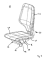
- FIG. 1 shows an exemplary embodiment of a seat device in the form of a chair 10.
- the chair 10 is designed as an office swivel chair. It comprises a support column 12, a back part 20, a seat 24 and a support structure 13 according to the invention for the back part 20 and the seat 24.
- the support structure 13 holds the back part 20 and the seat 24 respectively in a basic position, provided that the back part 20 or the seat 24 no load acts, and allows the back member 20 and the seat 24 can be deflected from the respective basic position, if a load acts on the back part or the seat 24.
- the back part 20 and the seat 24 unloaded and are therefore in the respective basic position. In this basic position, the backrest 22 is substantially vertical and the seat 24 is oriented substantially horizontally.
- the support structure includes, inter alia, a base support 14, which in the present example at an upper end of the support column 12 (optionally rotatable about a vertical axis and height adjustable) is arranged, and a support member 16.
- a base support 14 which in the present example at an upper end of the support column 12 (optionally rotatable about a vertical axis and height adjustable) is arranged, and a support member 16.
- One end of this support member 16 is rigid with a bearing shaft 18th connected, which is mounted on the base support 14 such that it is rotatable about its longitudinal direction.
- the support member 16 is therefore rotatable together with the bearing shaft 18 and thus pivotally mounted on the base support 14.
- the base support 14 further serves as a housing for accommodating mechanical elements, which will be described below, in particular in connection with the Fig. 2-10 ,
- the back part 20 comprises a backrest 22 and a connecting piece 21, which is formed as an angle profile, wherein the backrest 22 is fixed to one leg of this angle profile and the other leg of this angle profile for attachment of the back portion 20 to the support member 16 is used.
- the support member 16 at the end remote from the bearing shaft 18 a channel with an adapted to the outer contour of the connecting piece 21 opening, wherein the remote from the backrest 22 end of the connecting piece 21 can be inserted into this channel and then along this channel can be brought into a position relative to the support member 16, in which the connector 21 (with means not shown in the figures) on the support member 16 can be fixed.
- the back part 20 Fixed on the support part (as in Fig. 1 shown), the back part 20 is therefore rigidly coupled via the support member 16 to the bearing shaft 18 and thus pivotally mounted on the base support 14.
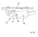
- the seat 24 rests on a seat support 28, which in the present case is pivotable about a pivot axis which is fastened on the support part 16 (as in FIG Fig. 3A is indicated).
- the seat support 28 is thus supported on the support part 16 at least in a partial area. Another portion of the seat support 28 may be supported on the base support 14.
- the support structure 13 additionally comprises a (in Fig. 1 Not shown) force system which generates a restoring force or a restoring torque, which restoring force acts on the support member 16 and which restoring force between the support member 16 and the base support 14 and a movement of the support member 16 relative to the in Fig. 1 counteracts the illustrated basic position.
- a force system will be described below in connection with Fig. 2-10 explained in more detail.
- the support part 16 accordingly carries the back part 20 and the seat 24 and holds the back part 20 and the seat 24 in a position which depends on the relative position of the support part 16 with respect to the base support 14.
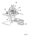
- Fig. 2 shows in a perspective view of the support structure 13 according to Fig. 1 including the base support 14 and the support member 16 and the seat support 28, wherein the back part 22 and the seat 24 is removed and accordingly in Fig. 2 are not shown.
- the bearing shaft 18 is positively connected via a attached to the support member 16 extension piece 26 rotatably connected to the support member 16.
- the seat support 28 is arranged, on which in turn the in Fig. 1 shown seat 24 can be attached.
- the carrier part 16 assumes in the present example, the basic position and, starting from this basic position in a clockwise direction (relative to the in Fig. 2 shown perspective) are pivoted about the longitudinal direction of the bearing shaft 18.
- the seat carrier 28 may be related to Fig. 1 described mechanical coupling
- the base support 14 is formed like a box and includes, for example, a force system 30 for generating a restoring force or a restoring torque, which restoring force on the support member 16 and which restoring torque between the support member 16 and the base support 14 acts and a movement of the support member 16 relative to the base support 14th is opposite.
- FIG. 3A and 3B each show the in FIG. 2 illustrated support structure 13 in a side view, wherein the base support 14 both in Fig. 3A as well as in Fig. 3B each assumes the same position in space.
- FIG. 3A shows the support structure 13 in a state in which the support member 16 is in the normal position.
- FIG. 3B shows the support structure 13 in a state in which the support member 16 is deflected from the basic position, that is rotated or pivoted clockwise relative to the basic position.
- FIG. 3B shown state adjusts as soon as a seated on the chair 10 person leans against the backrest 22 and thereby exerts a force on the backrest 22 and thus on the back support 16 so that the backrest 22 and thus the back support 16 performs a pivoting movement.
- the seat support 28 moves relative to the base support 14 (in comparison to the situation according to Fig. 3A ).
- the in FIG. 1 Seat 24 shown under the circumstances also moves synchronously with the backrest 22.
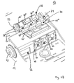
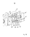
- FIGS. 4A and 4B show the in FIG. 2 In order to make details of the base support 14 and the power system 30 better recognizable, the support member 16 and the seat support 28 in Fig. 4A and 4B not shown.
- the force system 30 comprises a plurality of spring elements for generating a restoring force: in the present example, a "first" spring element 32 and three “second” spring elements 33 ', 33 “and 33”'.
- the spring elements 32, 33 ', 33 "and 33"' are each in the form of an elastomer Torsionsfederelements whose structure and operation hereinafter - especially in connection with Fig. 7A - Is described in more detail.
- first spring element 32 and the second spring elements 33 ', 33 "and 33"' respectively - as in Fig. 7A an inner housing 43, an outer housing 44 surrounding the inner housing 43, and an elastomeric body 46 arranged in an intermediate space between the inner housing 43 and the outer housing 44, the elastomeric body 46 being connected both to the inner housing 43 and to the outer housing 44 are firmly connected.
- the elastomeric body 46 is elastically deformed if the inner housing 43 is moved relative to the outer housing 44, and then generates between the inner housing 43 and the outer housing 44, a restoring force, which counteracts this movement. Accordingly, a restoring torque is generated between the inner housing 43 and the outer housing 44 if the inner housing 43 is rotated relative to the outer housing 44.
- the inner housing 43 of each of the spring elements 32, 33 ', 33 “and 33”' has a continuous channel whose cross section is formed such that the bearing shaft 18 through this channel is feasible and each of the spring elements 32, 33 ', 33 “and 33 “'can be plugged onto the bearing shaft 18 such that the respective inner housing 43 of each of the Spring elements 32, 33 ', 33 “and 33”' is positively connected to the bearing shaft 18 and is seated on the bearing shaft 18 such that the respective inner housing 43 is rotationally rigidly connected to the bearing shaft 18.
- the first spring element 32 of the power system 30 is coupled to both the base support 14 and the support member 16 in the following manner: a first portion of the spring member 32, ie, the inner housing 43 of the first spring member 32, is rotationally rigid with the first Bearing shaft 18 is connected and therefore rigidly coupled to the bearing shaft 18 and thus also to the support member 16 so that upon pivotal movement of the support member 16, the inner housing 18 is rotated about the axis of rotation of the bearing shaft 18; Furthermore, a second portion of the spring element 32, the outer housing 44 of the first spring element 32, rigidly connected to the base support 14 (which Fig. 4A and 4B is not apparent, but from the representation of the force system 30 in Fig. 5B is recognizable).
- the bearing shaft 18 and the inner housing 43 of the first spring member 32 are rotated together about the axis of rotation (longitudinal axis) of the bearing shaft 18, while the outer housing 44 is stationary with respect to the base support 14 is positioned. Accordingly, the inner housing 43 and the outer housing 44 of the first spring element 32 are rotated during a pivoting movement of the support member 16 relative to each other. Accordingly, while the elastomeric body 46 of the first spring member 32 is elastically deformed, so that the first spring member 32 a on the bearing shaft 18 and the Support member 16 generates acting restoring torque, which counteracts the pivotal movement of the support member 16.
- the power system 30 offers the possibility of bringing the second spring elements 33 ', 33 "and 33"' into a state (hereinafter referred to as “coupled state”) in which the respective spring element 33 ', 33 “or 33 '' to the base support 14 and the support member 16 is coupled, and further in another state (hereinafter “uncoupled state” called to bring), in which the respective second spring element 33 ', 33 “or 33”' not to the base support and / or the carrier part is coupled.
- the power system 30 comprises a coupling mechanism 34 for coupling the respective second spring element 33 ', 33 “or 33” to the base support 14 and / or the support part 16.
- the coupling mechanism 34 is fixed to the base support 13 and may (as hereinafter be explained) are brought into different states in which the coupling mechanism 34 optionally with the respective second spring element 33 ', 33 “or 33”' cooperates such that the respective second spring element 33 ', 33 “or 33”' in the coupled Condition is and in this state is able to generate a force acting on the support member 16 restoring force, or cooperates such that the respective spring element 33 ', 33 "or 33”' is in the uncoupled state and in this state in a position is to produce a force acting on the support member 16 restoring force.
- the first holding means 36 'for holding the outer housing 44 of the second spring element 36' is in the form of a movable part, which is attached to the base support 14 and (as will be explained in more detail below) on the one hand in a "first" position can be brought, in which the holding means 36 'is brought into contact with the outer housing 44 of the second spring element 33' and holds the outer housing 44 in a predetermined position relative to the base support 14, and on the other hand in a "second" position can be brought, in which the holding means 36 'not with the outer housing 44 of the outer housing 44 is in contact.
- first holding means 36 ' is a means for releasably holding the outer housing 44 of the second spring element 36', wherein the outer housing 44 is held by the first holding means 36 'only when the holding means 36' is in said first position , and the outer housing 44 separated from the first holding means 36 '(released) is, if the first holding means 36 'is in the second position.
- the above-mentioned 'coupling device' associated with the second spring element 33 ' has the property that when the first retaining means 36' is brought into said first position, the outer housing 44 of the second spring element 33 'is connected to the base support 14 and the inner housing 43 of the second spring elements 33 'is rigidly connected to the bearing shaft 18 and thus rigidly connected to the support member 16. In this case, the second spring element 33 'is in the already mentioned coupled state. If, however, the first holding means 36 'brought into said second position, the outer housing 44 of the second spring element 33' is not connected to the base support 14.
- the first spring element 33 ' is in the uncoupled state: in this case, the second spring element 33' is rotated together with the bearing shaft 18 when the bearing shaft 18 rotates about its longitudinal direction as a whole, with the inner housing 43 of the second spring element 33 '. is not rotated relative to the outer housing 44 and the elastomeric body 46 of the second spring element 33 'is not deformed. Accordingly, the second spring element 33 ', if the first holding means 36' is in the second position, generate on a pivoting movement of the support member 16 does not act on the support member 16 restoring force, which counteracts this pivotal movement.
- Coupled means of the coupling mechanism 34 associated with the respective second spring members 33 “and 33”' are constructed in structure and function analogous to that of the coupling means previously described in connection with the second spring member 33'. Accordingly includes the coupling mechanism 34 (analogous to the first holding means 36 ') a first holding means 36 “for releasably holding the outer housing 44 of the second spring element 33” and a first holding means 36''' for releasably holding the outer housing 44 of the second spring element 33 '''.
- the coupling mechanism 34 further comprises (analogous to the mentioned second holding means for the second spring element 33 ') a second holding means for holding the inner casing 43 of the spring element 33' (realized in the form of the already mentioned positive connection between the inner casing 43 of the spring element 33 "and the bearing shaft 18) and a second holding means for holding the inner housing 43 of the spring element 33 '''(realized in the form of the already mentioned positive connection between the inner housing 43 of the spring element 33''' and the bearing shaft 18)
- first holding means 36 ', 36 "and 36''' are arranged side by side in a row such that they are pivotable about a pivot axis 37 which is aligned parallel to the bearing shaft 18 and stationary relative to the base support 14 is arranged first holding means 36 ', 36 "and 36"' are each pivotable about the pivot axis 37 such that they can be selectively brought into contact with the outer housing 44 of the respective associated spring element 33 ', 33''and33''' (in the first position of the respective holding means) or are separable from the respective outer housing (in the second position of the respective holding means).
- the support structure 13 comprises an actuating means 38 for moving the respective first holding means 36 ', 36 "' and 36 '".
- the actuating means 38 in the present example comprise a rotatable camshaft 39, on the cams 40', 40 "and 40 '' are arranged, which in each case (in this order) one the first holding means 36 ', 36 "and 36"' are assigned.
- the cams 40 ', 40 "and 40”' are shaped such that upon rotation of the camshaft 39 (about the longitudinal axis of the camshaft 39) they drive the first holding means 36 ', 36 “and 36'” individually or in combination with one another to pivot the first holding means 36 ', 36 “and 36''' respectively about the pivot axis 37 and optionally with the outer housing 44 of the respectively associated second spring element 33 '. 33 '' and 33 '''to bring into contact.
- Fig. 4A and 4B show the camshaft 39 in a position in which the respective cams 40 ', 40 "and 40"' are arranged such that all the first holding means 36 ', 36 “and 36''' are arranged such that none of the holding means 36 ' , 36 '' and 36 '''in contact with one of the second spring elements 33', 33 "and 33 '''is brought. Accordingly, in this case, only the first spring element 32 is coupled both to the base support 14 and to the support part 16.
- all second spring elements 33 ', 33 "and 33'” are in the uncoupled state a pivoting movement of the support member 16 or at a corresponding rotation of the bearing shaft 18 exclusively the first spring element 32 acting on the bearing shaft 18 and the support member 16 restoring torque, which counteracts the pivotal movement of the support member 16 and the rotation of the bearing shaft 18.
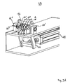
- FIG. 4B shows the in FIG. 4A illustrated coupling mechanism 34 from a different perspective.
- outer housing cams 42 '- 42''' can be seen, which are each attached to the outer housings 44 of the second spring elements 33'-33 '''or formed.
- outer housing cams 42 '- 42''' are arranged such that in each case that first holding means 36'-36 "', which by a corresponding Actuation of the actuating means 38 is brought into the first position, is brought into contact with the corresponding outer housing cam 42 '-42'”and forms a mechanical stop for this outer housing cam.
- first holding means 36'-36 "' which by a corresponding Actuation of the actuating means 38 is brought into the first position
- Fig.5A - 5C 14 show a detailed view of the support structure 13, wherein the spring elements 32, 33 ', 33 "and 33"' and the coupling mechanism 34 of the force system 30 are shown in different states Fig. 5A - 5c not shown (to clarify the facts presented).
- Such rotation for example, by a on the seat assembly 10 according Fig. 1 seated person are caused when leaning back against the backrest 22.
- Upon rotation of the bearing shaft 18 in the direction of the arrow 18 ' would only the first spring element 32 generate a restoring torque acting on the bearing shaft 18 (corresponding to the in Fig. 4A and 4B illustrated situation).
- Fig. 5B represents a state of the force system 30, which differs from the in Fig. 5A illustrated state in that the first holding means 36 '''is now in the first position (and accordingly with the in Fig. 5B and the bearing shaft 18 is rotated counterclockwise (ie, in the direction of the arrow 18 ') by a certain rotational angle in a state in which the second spring element 33 '''is in the coupled state and the second spring elements 33' and 33 "are in the uncoupled state.
- Fig. 5A shows is in the state according to Fig. 5B the spatial position of the outer housing of the first spring element 32 and the spatial position of the outer housing of the second spring element 32 '''unchanged (in comparison to the situation Fig.
- FIG. 5C shows a state dese power system 30 and the coupling mechanism 34, in which all the second spring elements 33'-33 "'are in the coupled state:
- the cams 40'-40''' are aligned by a suitable rotation of the camshaft 39 such that the first holding means 36'-36 '''are in the first position and are thus brought into contact with the outer housing cams 42' - 42 '' of the second spring elements 33'-33 '''.
- a (total) restoring torque which corresponds to the sum of all restoring torques generated by those spring elements 32, 33'-33 '", which are in each case in the coupled state and thus both acts on the bearing shaft 18 are coupled to the base support 14 and to the support member 16. Since in the in Fig. 5A shown state of the power system 30, only the first spring element 32 is in the coupled state, generates the power system 30 in the state according to Fig. 5A upon rotation of the bearing shaft 18 by a predetermined rotation angle ⁇ a reset torque with the lowest possible value and is therefore in this state tuned to persons with a relatively low body weight. Since in the in Fig.
- the power system 30 generates in the state according to Fig. 5C during a rotation of the bearing shaft 18 by the same (above-mentioned) rotation angle ⁇ a reset torque with the largest possible value and is therefore tuned in this state to persons with a relatively large body weight. Accordingly, the power system 30 generates in the state according to Fig. 5B upon rotation of the bearing shaft 18 by the same (above-mentioned) rotation angle ⁇ , a restoring torque whose value lies between the corresponding values of the restoring torque which the force system 30 in the states according to FIG Fig. 5A and 5C generated, and is therefore tuned to persons with a medium body weight.
- Fig. 6A and 6B show a schematic view of the power system 30 together with the coupling mechanism 34 and actuating means 38, wherein the base support 14 is not shown to detail the individual spring elements 32, 33'-33 "'(in particular their outer contours and their arrangement on the bearing shaft 18)
- the camshaft 39 is rotated such that the cams 40'-40 "'are positioned so that only the first holding means 36' is brought into the first position and thus (apart from the first spring element 32) only the second spring element 33 ' is in the coupled state.
- Fig. 6B shows the coupling mechanism 34 in a state in which none of the second spring members 33'-33 "'is set in the coupled state Fig. 6B The situation shown is therefore identical to that in Fig. 5A illustrated situation.
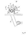
- FIG. 7A shows a schematic side view of the second Spring element 33 'in a plane perpendicular to a rotation axis 47 cutting plane.
- the spring elements 32, 33 'and 33 are identical in terms of their structural design with the spring element 33', so that in the following the properties of the spring elements 32 and 33'-33" based on the spring element 33 'according to Fig. 7A should be explained.
- the spring element 33 ' (as the spring elements 32, 33' and 33 ") is designed as an elastomer torsion spring element and comprises an inner housing 43 and an outer housing 44. In a space between the inner housing 43 and the outer housing 44 is a Elastomer body 46 is arranged.
- the inner housing 43 has on its outer side a contact surface 43 a, on which the elastomeric body 46 is in contact with the inner housing 43. Furthermore, the outer housing 44 has on its inside a contact surface 44a, on which the elastomeric body 46 is in contact with the outer housing 44.
- the contact surface 43a of the inner housing 43 and the contact surface 44a of the outer housing 44 enclose the axis of rotation 47 in each case in an annular manner. Accordingly, the elastomeric body 46 in the present example forms a closed ring surrounding the axis of rotation 47.
- the elastomeric body 46 is made of an elastomer, ie a solid and elastically deformable material.
- the elastomeric body 46 is formed such that it is fixedly connected to the contact surface 43 a of the inner housing 43 and the contact surface 44 a of the outer housing 44, ie upon movement of the inner housing 43 relative to the outer housing 44 (eg upon rotation of the inner housing 43 or Outer housing 44 about the axis of rotation 47) there is no displacement of the contact surfaces 43a and 44a adjacent surfaces of the elastomeric body 46 relative to the contact surfaces 43a and 44a instead.
- the elastomeric body 46 may, for example, material-fit or positive fit to the contact surfaces 43a and 44a to be connected to the inner housing 43 and the outer housing 44.
- a particularly well-suited for the production of the elastomeric body 46 elastomer is for example rubber, which is not only an elastically deformable and high-strength material, but also in a simple manner with the contact surfaces 43a and 44a can be firmly connected, for example by means of vulcanization.
- the inner housing 43 and the outer housing 44 are made of a solid material, such as steel.
- the respectively adjacent to the elastomer body 46 contact surfaces 43a and 44a of the inner housing 43 and the outer housing 44 differ - in a plane perpendicular to the axis of rotation 47 cutting plane - at least partially from a circular shape.
- pressure loads occur which compensate for tensile loads therein.
- the elastomeric body 46 is loaded non-homogeneously.
- Fig. 7A For example, the inner casing 43 is shown in a "non-rotated" state (solid line) and a “twisted state” (broken line), and the inner casing 43 is rotated about the rotation axis 47 in a twisted state as compared with the untwisted state by a rotation angle ⁇ in a clockwise direction is while the position of the outer housing 44 remains unchanged. It is assumed that the elastomeric body 46 is not biased in the case of the untwisted state, ie has no mechanical stresses. In the untwisted state, the distances from the upper right corner and the lower left corner of the inner housing 43 to respectively defined points on the inside of the outer housing 44 are shown with arrows x1 and y1, respectively.
- the distances from the upper right corner and the lower left corner of the inner housing 43 to respectively defined points on the inner side of the outer housing 44 are indicated by arrows x2 and y2, respectively.
- the distance x2 is less than x1 and the distance y2 is less than y1.
- the elastomeric body 46 is compressed when the inner housing 43 is rotated about the rotation axis 47 and thereby rotated relative to the outer housing 44. From these respective compressions result the above-mentioned pressure loads.
- the contact surface 43a of the inner housing 43 adjoining the elastomeric body 46 is square-shaped.
- the inner housing 43 is formed as a square sleeve (square), which has a parallel to the axis of rotation 47 extending, continuous channel 43.1 with a square cross-section.
- the shape of the cross section of the channel 43.1 is adapted to the cross-sectional shape of the bearing shaft 18, so that the bearing shaft 18 inserted through the channel 43.1 and the inner housing 43 - positively connected to the bearing shaft 18 - can sit on the bearing shaft (as already in connection with Fig. 4A and 4B mentioned).
- the adjacent to the elastomeric body 46 contact surface 44a of the outer housing 44 has a contour which is to be regarded as a combination of a rectangle and a circle. More specifically, the contour of the outer casing 44 is composed of two paired opposite isosceles angular segments, which in the present example enclose an angle of 90 °, and of two pairwise opposed semicircular segments whose ends are respectively connected to the ends of said angle segments.
- this "lemon-shaped" contour of the outer housing 44 in combination with the square contour of the inner housing 43, is particularly advantageous to provide an elastomeric torsion spring element whose characteristic of the restoring torque D in relation to Rotation angle ⁇ is linear in almost all areas of the rotation angle ⁇ .
- Fig. 7A further shows the exterior housing 44 formed on the outer housing cam 42 ', which already in connection with Fig. 4B and 5A-5C was mentioned.
- Fig. 7B shows that in Fig. 7A illustrated spring element 33 'with a holding element 48 in a perspective view.
- the holding element 48 serves to hold the inner housing 43 and the outer housing 44 in a "home position" relative to each other, in which the elastomeric body 46 has a mechanical stress (preload) and thus between the inner housing 43 and the outer housing 44, a restoring torque D. generated, which is different from zero.
- the inner housing 43 is opposite to the "unrotated" position (without bias) according to Fig. 7A by a rotational angle ⁇ (hereinafter referred to as "biasing angle") rotated, with respect to Fig. 7A clockwise and in terms of Fig. 7B in the counterclockwise direction.
- the holding element 48 contains in this example two clamping elements 49, which are each plugged onto one of the end faces of the spring element 33 '.
- the clamping element 49 is a substantially flat plate which is punched out in the center region in such a way that two opposite flanges 50 ', 50 "are left behind, these flanges being bent in each case by 90 ° inwards (into the plane of the figure) 49 tabs 52 ', 52' 'are formed, which are also bent by 90 ° inwards.
- the flanges 49 which are designed such that their outer regions are positively connected to the inner surface of the inner housing 43, to a first Distance plugged into the inner housing 43. Then, the clamping element 49 and thus radially positively connected to the inner housing 43, in a fixed outer housing 44, counterclockwise rotated by a certain angle (for example, 20 °) in relation to the outer housing 44.
- the clamping element 49 is pressed with its flanges 50 ', 50' 'completely into the channel 43.1 of the inner housing 43, wherein at the same time the tabs 52', 52 '' occupy a positive connection with the outer surface of the outer housing 44.
- the clamping element 49 maintains the bias. More precisely, the pretensioning angle ⁇ can no longer be undershot, since the tabs 52 ', 52 "abut against the outer surface of the outer housing 44. However, an increase in the rotational offset (also counterclockwise) between the inner housing 43 and the outer housing 44 is possible.
- the clamping element 49 can also in combination with the spring elements 32, 33 'and 33''analogous to that in Fig. 7B example used can be used. It should be noted that in the case of the power system 30 in the illustrations according to Fig. 4A . 4B , 5a 5C . 6A and FIG. 6b shows the respective second spring elements 33 ', 33 "and 33''' respectively in combination with two tensioning elements which correspond to the tensioning elements 49 Fig. 7B correspond (as in particular Fig. 6A and 6B hint).
- each of the second spring elements 33 ', 33 "and 33"' of the power system 30 generates upon rotation of the bearing shaft 18 each acting on a bearing shaft 18 restoring torque, which is greater than or equal to a predetermined (non-zero) minimum value, if the respective second spring element 33 ', 33 "or 33"' is in the coupled state.
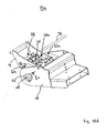
- Figures 8A-8C show (in different views) a variant of the force system 30 according to Figs. 3A-6B , which differs from the force system 30 according to Figs. 3A-6B essentially differs in that it (as a substitute for clamping elements in the manner of the clamping element 49 according to Fig. 7B ) Clamping elements 54 ', 54'', 54 "' and 54 '''', which in terms of their construction of the clamping elements 49 according to Fig. 7B differ.
- the variant of the power system 30 according to Figs. 8A-8C accordingly comprises (as the force system 30 according to Figs. 3A-6B ) also the bearing shaft 18, the first spring element 32 and the second spring elements 33 ', 33 "and 33"'.
- the coupling mechanism 34 and the actuating means 38 are in FIG Figs. 8A-8C not shown.
- the clamping elements 54'-54 "" are plate-like elements whose inner areas are punched rectangular. Here, the contour of the punched form fit to the outer contour of the (square) bearing shaft 18 is adjusted. At the outer regions of the clamping elements 54'-54 “” vaults 55'-55 "” are formed, each containing a vertical through hole.
- the bearing shaft 18 and the inner housing of the first spring element 32 are connected to each other in a radially form-fitting manner.
- all three second spring elements 33'-33"'with respectively interposed clamping elements 54'-54 "' are placed on the bearing shaft 18, is finally the last clamping element 54 '''' frontally attached.
- the second spring elements 33'-33 "'either individually or simultaneously biased by, for example, their outer housing, with radially fixed bearing shaft 18, are rotated in a clockwise direction about the longitudinal direction of the bearing shaft 18. This rotation takes place up to a rotational angle at which pins 56 ', 56 "through the respective holes of the bulges 55'-55" "can be inserted therethrough.
- the introduction of force for turning the outer casings is terminated, in which state the outer casings of the individual second spring elements 33'-33"' remain in this position, since the respective outer surfaces of the outer casings are now against a peripheral portion of the pins 56 ', 56 "abuts. Thus, it is no longer possible that the respective outer housing is rotated back to the initial state.
- Figs. 9A-9E show different views of a tensioning device 58 for biasing in the Figures 8A-8C shown spring elements 33'-33 "'with the intermediate and frontally mounted clamping elements 54'-54""
- Fig. 9A and 9C the tensioning device 58 is shown in a full view, viewed from different directions.
- Fig. 9B and 9D the tensioning device 58 is shown in a detail view, viewed from different directions.
- the clamping device 58 is used for easy and fast preloading of the individual spring elements 32'-32 '''with only a few steps.
- the tensioning device 58 contains fixing devices 60, which the bearing shaft 18 (not shown) fixedly clamped at their axial ends.
- the tensioning device 58 further includes a rod 62 which is perpendicularly connected between two lever arms of a lever 64.
- the lever arms are pivotally hinged via jig bearings 66 ', 66 ".
- the lever 64 is deflectable back and forth at its lower end by a drive 68.
- the rod 62 Upon deflection of the lower portion of the lever 64 in a direction out of the plane of the figure Fig. 9A out, the rod 62 is deflected toward the spring elements 33'-33 '", as indicated by an arrow A.
- a further surface region of the rod 62 engages with the outer surface of the outer housing of a further spring element, in this example with the outer housing of the spring element 33 ''
- the previously brought into engagement outer surface of the outer housing of the spring element 33 "'is pivoted or rotated.
- a region of the outer surface of the outer housing of a further spring element in this example the outer housing of the spring element 33 ', is engaged.
- Figure 9E shows the tensioning device 58 in a view viewed axially with respect to the tensioning device bearings 66 ', 66 ". It can be seen particularly clearly in this figure that the individual spring elements 33'-33"' are each deflected differently in their initial state. This is due to the fact that the respective inner housings of the spring elements 33'-33 "'are arranged in each case with a rotational offset in relation to the contour of their respective outer housings, which is in each case of different size for the spring elements 33'-33"'. The rotational offsets can for the spring elements 33'-33 "'example 20 °, 25 ° and 40 °.
- the individual spring elements 33'-33 are thus biased to different degrees, thus forcing the spring element 33"'stronger than the spring element 33 ", which in turn is more strongly biased is used as the spring element 33 ' FIGS. 9A and 9C-9E
- the pins 56 ', 56 can be inserted through the bores of the bulges 55' - 55 1 ""of the respective clamping elements 54 '- 54""after pretensioning, thus making the respective prestressing of the individual spring elements 33'-33 '' by the pins 56 ', 56 "maintained.
- Fig. 10A shows a support structure according to the invention 13a, which a variant of the support structure 13 according to Fig. 2 represents.
- Those components which have the support structures 13A and 13B in common are referred to below with the same reference numerals.
- the support structure 13a according to Fig. 10A comprises - as the support structure 13 according to Fig. 2 - A base support 14 and a support member 16 (for supporting and / or holding the back part 20 and / or the respective seat 24 according to Fig. 1 ).
- the support member 16 is rotationally rigidly connected via an extension piece 26 to the ends of a rotatable bearing shaft 18, so that the support member 16 about the longitudinal axis of the bearing shaft 18 in the direction of the arrow 18 'is pivotable.
- the Fig. 10B also shows the support structure 13A according to Fig. 10A , with the only difference being that in the Fig. 10B the carrier part 16 is not shown.
- the support structure 13a comprises a force system 30a which comprises two first spring elements 32a and second spring elements 33 ', 33 "and 33"'.
- the spring elements 32a, 33 ', 33 "and 33"' are each designed as an elastomer torsion spring element and are identical in terms of their structure with the spring element 33 'according to Fig. 7A ie they each have an inner housing 43, an outer housing 44 surrounding the inner housing 43 and an elastomeric body 46 arranged in an intermediate space between the inner housing 43 and the outer housing 44, which is fixedly connected to the inner housing 43 and the outer housing 44.
- the second spring elements 33 ', 33 "and 33"' of the power system 30a are identical to the spring elements 33 ', 33 "and 33"' of the power system 30.
- the first spring element 32a of the power system 30a differs from the first spring element 32 of the force system 30 in its construction substantially by the shape of the cross section of the outer housing 44. The latter, however, with regard to Function of the first spring element 32a in this context is not important.
- Fig. 10B indicates, sit the spring elements 32a, 33 ', 33 "and 33"' of the power system 30a on the bearing shaft 18 such that the inner housing 43 of the spring elements are each rotationally rigidly connected to the bearing shaft 18.
- the outer housing 44 of the respective first spring element 32a is rigidly connected to the base support 14, while the inner housing 43 together with the bearing shaft 18 in the direction of the arrow 18 'can be rotated.
- the two first spring elements 32a are accordingly coupled in the sense of the invention both to the base support 14 and to the support member 16, so that the first spring elements 32a in a pivotal movement of the support member 16 in the direction of arrow 18 'each generate a restoring torque, which the pivoting movement of the Support member 16 is directed opposite.
- the second spring elements 33 ', 33 "and 33”' of the power system 33a functionally correspond to the second spring elements 33 ', 33 "and 33”' of the power system 30.
- the support structure 13a also includes the same coupling mechanism 34 and the actuating means 38 for controlling the coupling mechanism in that the respective second spring elements 33 ', 33 “and 33”' are selectively in the coupled state (in which the respective spring element 33 ', 33 “and 33”' via the coupling mechanism 34 both to the base support 14 and to the support member 16th is coupled) or in the uncoupled state (in which the respective spring element 33 ', 33 " 1 and 33"' is not coupled to the base support 14 and / or to the support member 16) can be brought.
- a significant feature of the power system 13a is the fact that the support member 16 and the two ends of the Bearing shaft 18 are always coupled via the elastomeric body 46 of the two first spring elements 32a to the base support 14, wherein the elastomeric body 46 can receive a radially acting on the bearing shaft 18 load.
- the bearing shaft 18 does not require a separate pivot bearing, which rotatably supports the bearing shaft 18 on the base support 14.
- the first spring elements 32a serve as a bearing for the bearing shaft 18, in particular when none of the second spring elements 33'-33 "'is switched to the coupled state Condition is also used this spring element as a bearing for the bearing shaft 18 with respect to the base support fourteenth
- the spring elements 32a thus exert a double function: as a means for generating a force acting on the support member 16 restoring force and as a bearing for the storage of the bearing shaft 18.
Claims (18)
- Structure porteuse (13, 13a) pour une partie dossier (20) et/ou une assise (24) d'un siège (10), aveca) un support de base (14),b) au moins une pièce porteuse (16) disposée sur le support de base (14) pour porter et/ou pour maintenir la partie dossier (20) concernée et/ou l'assise (24) concernée, laquelle pièce porteuse étant fixée au support de base de telle sorte qu'un déplacement (18') de la pièce porteuse (16) par rapport au support de base (14) soit réalisable,c) un système de force (30, 30a) pour générer au moins une force de rappel qui est générée lors du déplacement (18') concerné de la pièce porteuse (16) et qui est opposée audit déplacement,
le système de force (30, 30a) comprenant au moins un premier élément à ressort (32, 32a) qui est accouplé au support de base (14) et à la pièce porteuse (16) de telle sorte que lors du déplacement concerné de la pièce porteuse (16), le premier élément à ressort (32, 32a) génère une première force de rappel qui est opposée au déplacement concerné de la pièce porteuse,
caractérisée en ce que le système de force (30, 30a) comprend :d) au moins un deuxième élément à ressort (33', 33" 33"'),e) au moins un dispositif d'accouplement (36', 36", 36"') pour accoupler le deuxième élément à ressort (33', 33" , 33"') concerné avec le support de base (14) et/ou la pièce porteuse (16),
lequel dispositif d'accouplement (36', 36", 36"') pouvant être amené au choix dans un premier ou dans un deuxième état,
si le dispositif d'accouplement (36', 36", 36"') est amené dans le premier état, le deuxième élément à ressort (33', 33" , 33"') concerné étant accouplé au support de base (14) et à la pièce porteuse (16) de telle sorte que le deuxième élément à ressort (33', 33", 33"') concerné génère lors du déplacement concerné de la pièce porteuse (16) une deuxième force de rappel, qui est opposée au déplacement (18') concerné de la pièce porteuse (16) et
si le dispositif d'accouplement est amené dans le deuxième état, le deuxième élément à ressort (33', 33", 33"') concerné n'étant pas accouplé au support de base (14) et/ou à la pièce porteuse (16), de telle sorte que le deuxième élément à ressort (33', 33", 33"') concerné ne génère aucune force de rappel opposée au déplacement (18') concerné de la pièce porteuse (16). - Structure porteuse (13, 13a) selon la revendication 1, avec un dispositif de commande (38) pour influencer l'état respectif du dispositif d'accouplement (36' , 36'', 36''') concerné, de telle sorte que le dispositif d'accouplement concerné puisse être amené au choix dans le premier ou dans le deuxième état.
- Structure porteuse (13, 13a) selon l'une quelconque des revendications 1 ou 2, avec plusieurs deuxièmes éléments à ressort (33', 33'', 33"') et plusieurs dispositifs d'accouplement (36', 36", 36'''), chaque fois deux dispositifs d'accouplement pouvant être amenés indépendamment l'un de l'autre dans le premier ou dans le deuxième état.
- Structure porteuse (13, 13a) selon la revendication 3, les deuxièmes éléments à ressort (33', 33", 33"') concernésa) pouvant être amenés chacun dans un état, dans lequel aucun des deuxièmes éléments à ressort (33', 33'', 33''') n'est accouplé au support de base (14) et à la pièce porteuse (16) oub) pouvant être amenés chacun dans un état, dans lequel l'un des deuxièmes éléments à ressort (33', 33", 33"') est accouplé au support de base (14) et à la pièce porteuse (16) ouc) pouvant être amenés chacun dans un état, dans lequel plusieurs des deuxièmes éléments à ressort (33', 33", 33"') sont accouplés au support de base (14) et à la pièce porteuse (16).
- Structure porteuse (13, 13a) selon l'une quelconque des revendications 1 à 4,
le deuxième élément à ressort (33', 33'', 33"') concerné présentant une première partie (44) et une deuxième partie (43), lesquelles parties sont mobiles l'une par rapport à l'autre, pour générer la force de rappel concernée et
le dispositif d'accouplement comprenant :(i) un premier moyen de retenue (36' , 36" , 36"') pour maintenir la première partie (43) du deuxième élément à ressort (33', 33", 33"') concerné, lequel premier moyen de retenue (36', 36", 36"') étant relié au support de base (14) et étant conçu pour coopérer avec la première partie (44) du deuxième élément à ressort (33', 33", 33''') concerné, de telle sorte que (si le dispositif d'accouplement (36' , 36", 36"') est amené dans le premier état), ladite première partie (44) du deuxième élément à ressort (33', 33" , 33"') concerné soit maintenue dans un position prédéfinie par rapport au support de base (14) et(ii) un deuxième moyen de retenue pour maintenir la deuxième partie du deuxième élément à ressort concerné, lequel deuxième moyen de retenue étant relié à la pièce porteuse et conçu pour coopérer avec la deuxième partie du deuxième élément à ressort concerné, de telle sorte que (si le dispositif d'accouplement est amené dans le premier état), ladite deuxième partie du deuxième élément à ressort concerné soit maintenue dans une position prédéfinie par rapport à la pièce porteuse. - Structure porteuse (13, 13a) selon la revendication 5,(i) le premier moyen de retenue (36', 36'', 36"') étant conçu pour le maintien amovible de la première partie (44) du deuxième élément à ressort (33', 33", 33"') concerné et (si le dispositif d'accouplement (36', 36" , 36"') est amené dans le deuxième état), étant amené dans un état dans lequel la première partie (44) du deuxième élément à ressort (33' , 33", 33''') concerné est détachée du premier moyen de retenue (36', 36", 36''') concerné, lors du déplacement (18') respectif de la pièce porteuse (16) et/ou(ii) le deuxième moyen de retenue étant conçu pour le maintien amovible de la deuxième partie du deuxième élément à ressort concerné et (si le dispositif d'accouplement est amené dans le deuxième état), étant amené dans un état dans lequel la deuxième partie du deuxième élément à ressort concerné est détachée du deuxième moyen de retenue concerné lors du déplacement respectif de la pièce porteuse.
- Structure porteuse (13, 13a) selon la revendication 6,(i) le premier moyen de retenue (36', 36'', 36''') étant une pièce mobile, que l'on peut amener dans au moins deux positions différentes, dans l'une de ces positions, le premier moyen de retenue étant en contact avec la première partie (44) du deuxième élément à ressort (33', 33" , 33"') concerné, de telle sorte que ladite première partie soit maintenue dans la position définie par rapport au support de base (14) et que dans l'autre de ces positions soit séparée de la première partie (44) du deuxième élément à ressort (33', 33", 33"') concerné et/ou(i) le deuxième moyen de retenue étant une pièce mobile, que l'on peut amener dans au moins deux positions différentes, dans l'une de ces positions, le deuxième moyen de retenue étant en contact avec le deuxième élément à ressort concerné, de telle sorte que cette deuxième partie soit maintenue dans la position prédéfinie par rapport à la pièce porteuse et dans l'autre de ces positions, soit séparée de la deuxième partie du deuxième élément à ressort concerné.
- Structure porteuse (13, 13a) selon la revendication 7, avec un moyen de manoeuvre (38) pour déplacer le moyen de retenue (36', 36", 36"') concerné de l'une des positions dans une autre des positions.
- Structure porteuse (13, 13a) selon la revendication 8,
le moyen de manoeuvre (38) étant un arbre à cames (39) rotatif, sur lequel au moins l'une des cames (40', 40", 40"') associée au moyen de retenue (36', 36", 36"') concerné est disposée de telle sorte que lors d'un déplacement en rotation de l'arbre à cames (39), le moyen de retenue (36', 36", 36"') concerné soit mobile au moyen de la came (40', 40", 40"') respectivement associée. - Structure porteuse (13, 13a) selon l'une quelconque des revendications 1 à 9,
le premier élément à ressort (32, 32a) concerné étant un élément de torsion à ressort en élastomère, lequel comprend un boîtier intérieur (43), un boîtier extérieur (44) entourant le boîtier intérieur (43) et un corps en élastomère (46) disposé dans un espace intermédiaire entre le boîtier intérieur (43) et le boîtier extérieur (44),
lequel boîtier intérieur (43) comprenant au moins une surface de contact (43a) sur laquelle le corps en élastomère (46) est en contact avec le boîtier intérieur (43),
lequel boîtier extérieur (44) comprenant au moins une surface de contact (44a) sur laquelle le corps en élastomère (46) est en contact avec le boîtier extérieur (44),
le corps en élastomère (46) étant solidement relié avec la surface de contact (43a) du boîtier intérieur (43) et la surface de contact (14a) du boîtier extérieur (44),
le boîtier intérieur (43) et/ou le boîtier extérieur (44) étant disposé de manière rotative autour d'un axe de rotation (47),
l'élément de torsion à ressort en élastomère étant accouplé au support de base (14) et à la pièce porteuse (16) de telle sorte que le déplacement (18') concerné de la pièce porteuse (16) provoque une rotation du boîtier intérieur (43) et/ou du boîtier extérieur (44) autour de l'axe de rotation (47),
lors de ladite rotation, le boîtier intérieur (43) étant déplacé par rapport au boîtier extérieur (44) et à cet effet, une déformation du corps en élastomère (46) étant générée, de telle sorte que le corps en élastomère (46) génère entre le boîtier extérieur (43) et le boîtier intérieur (44) un couple de rappel qui est opposé à la rotation. - Structure porteuse (13, 13a) selon la revendication 10,
la pièce porteuse (16) étant fixée sur un arbre de support (18) qui est logé sur le support de base (14), de telle sorte que la pièce porteuse (16) puisse pivoter autour d'un axe de pivotement et(i) le boîtier extérieur (44) étant relié de manière rigide avec le support de base (14) et le boîtier intérieur (43) avec la pièce porteuse (16) ou l'arbre de support (18) ou(ii) le boîtier intérieur (43) étant relié de manière rigide avec le support de base (14) et le boîtier extérieur (44) avec la pièce porteuse (16) ou l'arbre de support (18). - Structure porteuse (13, 13a) selon l'une quelconque des revendications 1 à 10,
le deuxième élément à ressort (33', 33'', 33''') concerné étant un élément de torsion à ressort en élastomère, lequel comprend un boîtier intérieur (43), un boîtier extérieur (44) entourant le boîtier intérieur (43) et un corps en élastomère (46) disposé dans un espace intermédiaire entre le boîtier intérieur (43) et le boîtier extérieur (44),
lequel boîtier intérieur (43) comportant au moins une surface de contact (43a) sur laquelle le corps en élastomère (46) est en contact avec le boîtier intérieur (43),
lequel boîtier extérieur (44) comportant au moins une surface de contact (44a) sur laquelle le corps en élastomère (46) est en contact avec le boîtier extérieur (44),
le corps en élastomère (46) étant solidement relié avec la surface de contact (43a) du boîtier intérieur (43) et la surface de contact (44a) du boîtier extérieur (44),
le boîtier intérieur (43) et/ou le boîtier extérieur (44) étant disposé en étant rotatif autour d'un axe de rotation (47),
si le dispositif d'accouplement (36', 36", 36"') est amené dans le premier état, l'élément de torsion à ressort en élastomère concerné étant accouplé au support de base (14) et à la pièce porteuse (16) de telle sorte que le déplacement (18') concerné de la pièce support (16) provoque une rotation du boîtier intérieur (43) et/ou du boîtier extérieur (44) autour de l'axe de rotation (47),
lors de ladite rotation, le boîtier intérieur (43) étant déplacé par rapport au boîtier extérieur (44) et à cet effet, une déformation du corps en élastomère (46) étant générée, de telle sorte que le corps en élastomère (46) génère entre le boîtier extérieur (43) et le boîtier intérieur (44) un couple de rappel qui est opposé à la rotation. - Structure porteuse (13, 13a) selon la revendication 12, la pièce porteuse (16) étant fixée sur un arbre de support (18) qui est logé sur le support de base (14), de telle sorte que la pièce porteuse (16) puisse pivoter autour d'un axe de pivotement et si le dispositif d'accouplement (36', 36", 36"') est amené dans le premier état, (i) le boîtier extérieur (44) étant relié de manière rigide avec le support de base (14) et le boîtier intérieur (43) avec la pièce porteuse (16) ou l'arbre de support (18) ou (ii) le boîtier intérieur (43) étant relié de manière rigide avec le support de base (14) et le boîtier extérieur (44) avec la pièce porteuse (16) ou l'arbre de support (18).
- Structure porteuse (13, 13a) selon l'une quelconque des revendications 10 à 13,
dans un plan de coupe perpendiculaire à l'axe de rotation (47), la surface de contact (43a) du boîtier intérieur (43) présentant une section transversale non circulaire et/ou dans un plan de coupe perpendiculaire à l'axe de rotation (47), la surface de contact (44a) du boîtier extérieur (44) présentant une section transversale non circulaire. - Structure porteuse (13, 13a) selon l'une quelconque des revendications 10 à 14,
sur l'élément de torsion à ressort en élastomère concerné étant disposé un élément de retenue (48) lequel est conçu pour(i) maintenir le boîtier intérieur (43) de l'élément de torsion à ressort en élastomère dans une position de base prédéfinie par rapport au boîtier extérieur (44) de l'élément de torsion à ressort en élastomère, dans laquelle position de base, le corps en élastomère (47) présentant une déformation élastique prédéfinie et générant entre le boîtier extérieur (44) et le boîtier intérieur (43) un couple de rappel qui est identique à une valeur minimale prédéfinie et(ii) libérer une rotation du boîtier intérieur (43) par rapport au boîtier extérieur (44) autour d'un angle de rotation (ϕ) autour de l'axe de rotation (47), dans un sens de rotation dans lequel le couple de rappel augmente au fur et à mesure de l'augmentation de l'angle de rotation (ϕ). - Structure porteuse (13, 13a) selon la revendication 15,
sur laquelle l'élément de retenue (49, 54' à 54''') contient au moins un élément de serrage, lequel soit(i) comporte une première partie, qui est en engagement fixe avec le boîtier intérieur (43) et une deuxième partie, qui (lorsque le boîtier intérieur (43) se trouve dans la position de base prédéfinie par rapport au boîtier extérieur) bute contre une partie du boîtier extérieur (44) et libère une rotation du boîtier intérieur (43) et du boîtier extérieur (44) en relation réciproque autour de l'axe de rotation (47), dans le sens de rotation dans lequel le couple de rappel augmente ou(ii) comporte une première partie, qui est en engagement fixe avec le boîtier extérieur (44) et une deuxième partie, qui (lorsque le boîtier intérieur (43) se trouve dans la position de base prédéfinie par rapport au boîtier extérieur (44)) bute contre une partie du boîtier intérieur (43) et libère une rotation du boîtier intérieur (43) et du boîtier extérieur (44) en relation réciproque autour de l'axe de rotation (47), dans le sens de rotation dans lequel le couple de rappel augmente. - Structure porteuse (13, 13a) selon la revendication 16,
sur laquelle le boîtier intérieur (43) comprend un évidement (43.1) et la première partie de l'élément de serrage (49) est insérée de manière solidaire en rotation dans ledit évidement (43.1) dans le boîtier intérieur (43) et (lorsque le boîtier intérieur (43) se trouve dans la position de base prédéfinie par rapport au boîtier extérieur (44)), la deuxième partie de l'élément de serrage (49) bute contre une partie du boîtier extérieur (44). - Siège (10),
avec une assise (24),
une partie dossier (20) et
une structure porteuse (13, 13a) selon l'une quelconque des revendications 1 à 17,
la pièce porteuse (16) portant la partie dossier (20) et/ou l'assise (24) et/ou maintenant la partie dossier (20) et/ou l'assise (24) dans une position qui dépend de la position relative de la pièce porteuse (16) par rapport au support de base (14).
Priority Applications (4)
| Application Number | Priority Date | Filing Date | Title |
|---|---|---|---|
| EP10405014A EP2347676B1 (fr) | 2010-01-22 | 2010-01-22 | Structure porteuse pour un élément de dossier et/ou un siège d'un dispositif d'assise et dispositif d'assise doté d'une telle structure porteuse |
| BRPI1100071-6A BRPI1100071A2 (pt) | 2010-01-22 | 2011-01-11 | estrutura de suporte para uma parte posterior e/ou um assento e montagem de assento que compreende tal estrutura de suporte |
| US13/006,830 US20110181086A1 (en) | 2010-01-22 | 2011-01-14 | Support structure for a back part and/or a seat of a seat assembly and seat assembly comprising such a support structure |
| JP2011012099A JP2011147788A (ja) | 2010-01-22 | 2011-01-24 | 座席組立体の背もたれ部分および/または座部の支持構造、およびその支持構造を備えた座席組立体 |
Applications Claiming Priority (1)
| Application Number | Priority Date | Filing Date | Title |
|---|---|---|---|
| EP10405014A EP2347676B1 (fr) | 2010-01-22 | 2010-01-22 | Structure porteuse pour un élément de dossier et/ou un siège d'un dispositif d'assise et dispositif d'assise doté d'une telle structure porteuse |
Publications (2)
| Publication Number | Publication Date |
|---|---|
| EP2347676A1 EP2347676A1 (fr) | 2011-07-27 |
| EP2347676B1 true EP2347676B1 (fr) | 2012-08-22 |
Family
ID=42104388
Family Applications (1)
| Application Number | Title | Priority Date | Filing Date |
|---|---|---|---|
| EP10405014A Not-in-force EP2347676B1 (fr) | 2010-01-22 | 2010-01-22 | Structure porteuse pour un élément de dossier et/ou un siège d'un dispositif d'assise et dispositif d'assise doté d'une telle structure porteuse |
Country Status (4)
| Country | Link |
|---|---|
| US (1) | US20110181086A1 (fr) |
| EP (1) | EP2347676B1 (fr) |
| JP (1) | JP2011147788A (fr) |
| BR (1) | BRPI1100071A2 (fr) |
Families Citing this family (21)
| Publication number | Priority date | Publication date | Assignee | Title |
|---|---|---|---|---|
| US9458905B2 (en) * | 2012-09-20 | 2016-10-04 | Steelcase Inc. | Spring assembly and method |
| US11304528B2 (en) | 2012-09-20 | 2022-04-19 | Steelcase Inc. | Chair assembly with upholstery covering |
| USD697726S1 (en) | 2012-09-20 | 2014-01-21 | Steelcase Inc. | Chair |
| DE202014100062U1 (de) * | 2014-01-08 | 2015-04-10 | Innotec Motion GmbH | Sitzmöbel mit federnder Rückenlehne |
| US11259637B2 (en) | 2015-04-13 | 2022-03-01 | Steelcase Inc. | Seating arrangement |
| US10194750B2 (en) | 2015-04-13 | 2019-02-05 | Steelcase Inc. | Seating arrangement |
| JP6695157B2 (ja) * | 2016-02-02 | 2020-05-20 | 株式会社オカムラ | 椅子 |
| USD827352S1 (en) | 2017-05-25 | 2018-09-04 | Steelcase Inc. | Seating arrangement |
| USD852524S1 (en) | 2017-05-25 | 2019-07-02 | Steelcase Inc. | Seating arrangement |
| USD851417S1 (en) | 2017-05-25 | 2019-06-18 | Steelcase Inc. | Seating arrangement |
| USD829033S1 (en) | 2017-05-25 | 2018-09-25 | Steelcase Inc. | Seating arrangement arm structure |
| USD846294S1 (en) | 2017-05-25 | 2019-04-23 | Steelcase Inc. | Seating arrangement |
| USD852526S1 (en) | 2017-05-25 | 2019-07-02 | Steelcase Inc. | Seating arrangement |
| USD851952S1 (en) | 2017-05-25 | 2019-06-25 | Steelcase Inc. | Seating arrangement |
| USD852525S1 (en) | 2017-05-25 | 2019-07-02 | Steelcase Inc. | Seating arrangement |
| USD851418S1 (en) | 2017-05-25 | 2019-06-18 | Steelcase Inc. | Seating arrangement |
| CN209018141U (zh) * | 2018-05-11 | 2019-06-25 | 杭州中泰实业集团有限公司 | 一种改变扭簧角度的螺旋调节转椅托盘 |
| WO2020172243A1 (fr) | 2019-02-21 | 2020-08-27 | Steelcase Inc. | Ensemble support corporel et procédés d'utilisation et d'assemblage de cet ensemble |
| USD907383S1 (en) | 2019-05-31 | 2021-01-12 | Steelcase Inc. | Chair with upholstered back |
| USD907935S1 (en) | 2019-05-31 | 2021-01-19 | Steelcase Inc. | Chair |
| US11357329B2 (en) | 2019-12-13 | 2022-06-14 | Steelcase Inc. | Body support assembly and methods for the use and assembly thereof |
Family Cites Families (18)
| Publication number | Priority date | Publication date | Assignee | Title |
|---|---|---|---|---|
| US4438898A (en) * | 1980-05-01 | 1984-03-27 | Steelcase Inc. | Chain control locking assembly |
| US4597567A (en) * | 1984-10-26 | 1986-07-01 | Barry Wright Corporation | Adjustable torsion spring |
| US4776633A (en) * | 1986-04-10 | 1988-10-11 | Steelcase Inc. | Integrated chair and control |
| US5567012A (en) * | 1986-04-10 | 1996-10-22 | Steelcase, Inc. | Chair control |
| EP1486142A1 (fr) | 1992-06-15 | 2004-12-15 | Herman Miller, Inc. | Structure d'assise pour chaise |
| US5782536A (en) * | 1995-02-17 | 1998-07-21 | Steelcase Inc. | Modular chair construction and method of assembly |
| US5765914A (en) * | 1995-06-07 | 1998-06-16 | Herman Miller, Inc. | Chair with a tilt control mechanism |
| US5909924A (en) * | 1997-04-30 | 1999-06-08 | Haworth, Inc. | Tilt control for chair |
| WO2000022959A1 (fr) * | 1998-10-20 | 2000-04-27 | Protoned B.V. | Systeme mecanique pour fauteuil |
| US6705677B2 (en) * | 2000-02-18 | 2004-03-16 | Sugatsun Kogyo Co., Ltd | Chair with seatback and rotating damper device |
| WO2001070073A1 (fr) * | 2000-03-17 | 2001-09-27 | Herman Miller, Inc. | Ensemble basculeur destine a une chaise |
| DE10126001A1 (de) * | 2001-05-18 | 2002-11-21 | Bock 1 Gmbh & Co | Vorgespannte Federanordnung, insbesondere zur Federbeaufschlagung von Synchronmechaniken von Bürostühlen |
| US6682252B2 (en) * | 2002-03-01 | 2004-01-27 | Steelcase Development Corporation | Torsional energy joint for seating unit |
| JP4087654B2 (ja) * | 2002-07-23 | 2008-05-21 | 株式会社岡村製作所 | 椅子における背凭れ等の傾動装置 |
| EP1527714B1 (fr) * | 2002-07-23 | 2008-11-26 | Okamura corporation | Chaise |
| EP1855567B1 (fr) * | 2005-03-01 | 2015-09-23 | Haworth, Inc. | Mecanisme de controle d'inclinaison d'un fauteuil |
| EP1971245B1 (fr) * | 2006-01-12 | 2012-01-18 | Bock 1 GmbH & Co. KG | Mecanisme a contact permanent |
| DE202007006762U1 (de) * | 2006-10-13 | 2008-02-14 | Bock 1 Gmbh & Co. Kg | Mechanik für einen Bürostuhl |
-
2010
- 2010-01-22 EP EP10405014A patent/EP2347676B1/fr not_active Not-in-force
-
2011
- 2011-01-11 BR BRPI1100071-6A patent/BRPI1100071A2/pt not_active IP Right Cessation
- 2011-01-14 US US13/006,830 patent/US20110181086A1/en not_active Abandoned
- 2011-01-24 JP JP2011012099A patent/JP2011147788A/ja active Pending
Also Published As
| Publication number | Publication date |
|---|---|
| EP2347676A1 (fr) | 2011-07-27 |
| US20110181086A1 (en) | 2011-07-28 |
| BRPI1100071A2 (pt) | 2013-04-24 |
| JP2011147788A (ja) | 2011-08-04 |
Similar Documents
| Publication | Publication Date | Title |
|---|---|---|
| EP2347676B1 (fr) | Structure porteuse pour un élément de dossier et/ou un siège d'un dispositif d'assise et dispositif d'assise doté d'une telle structure porteuse | |
| EP2347678B1 (fr) | Dispositif de siège avec elément de ressort de torsion en élastomère | |
| EP3019047B1 (fr) | Mécanisme pour chaise de bureau | |
| DE102012212950A1 (de) | Schwenkvorrichtung für einen Fahrzeugsitz | |
| EP3094212A1 (fr) | Articulation à pivot et meuble équipé d'une telle articulation à pivot | |
| WO2006074763A9 (fr) | Meuble, en particulier meuble d'assise | |
| EP3263396A1 (fr) | Système de suspension | |
| DE202011002608U1 (de) | Stativkopf | |
| DE102005021673A1 (de) | Geteilter elektromechanischer Kraftfahrzeugstabilisator mit Blockiereinrichtung und Verfahren zur Wankstabilisierung bei Ausfall oder Abschaltung des aktiven Kraftfahrzeugstabilisators | |
| EP3116347B1 (fr) | Siège rotatif | |
| DE60024207T2 (de) | Drehbaugruppe für einen drehstuhl | |
| DE10214469B4 (de) | Armlehne für ein Fahrzeug, insbesondere für ein Kraftfahrzeug | |
| DE102007018029B3 (de) | Stativkopf | |
| EP2625442B1 (fr) | Roue libre à rouleaux de serrage pour un dispositif de réglage dans un véhicule automobile | |
| DE2312246A1 (de) | Lager fuer eine elektrische kupplung eines automatischen kupplungskopfes fuer schienenfahrzeuge | |
| DE102008036647A1 (de) | Taumelgelenkbeschlag für einen Kraftfahrzeugsitz | |
| EP3437520B1 (fr) | Mécanisme basculant | |
| DE102012104101B4 (de) | Radialverstellung mit Arretierfunktion | |
| DE102010045733A1 (de) | Auflagerelement einer Sitz- oder Liegemöbelunterfederung | |
| DE1529417B2 (de) | Schaukelteil | |
| WO2013167100A1 (fr) | Dispositif de réglage radial à fonction de blocage | |
| DE202014103388U1 (de) | Auflagerelement eines Sitz- oder Liegemöbels | |
| DE102020007392B4 (de) | Arretierungsvorrichtung für Möbel, drehbares Möbel und Verfahren zum Arretieren eines drehbaren Möbels | |
| EP2801296B1 (fr) | Élément à ressort simple d'un sommier | |
| EP2708763A2 (fr) | Liaison rotule avec un élément mobile de verrouillage |
Legal Events
| Date | Code | Title | Description |
|---|---|---|---|
| PUAI | Public reference made under article 153(3) epc to a published international application that has entered the european phase |
Free format text: ORIGINAL CODE: 0009012 |
|
| AK | Designated contracting states |
Kind code of ref document: A1 Designated state(s): AT BE BG CH CY CZ DE DK EE ES FI FR GB GR HR HU IE IS IT LI LT LU LV MC MK MT NL NO PL PT RO SE SI SK SM TR |
|
| AX | Request for extension of the european patent |
Extension state: AL BA RS |
|
| GRAP | Despatch of communication of intention to grant a patent |
Free format text: ORIGINAL CODE: EPIDOSNIGR1 |
|
| 17P | Request for examination filed |
Effective date: 20120124 |
|
| RIC1 | Information provided on ipc code assigned before grant |
Ipc: A47C 1/032 20060101AFI20120213BHEP |
|
| GRAS | Grant fee paid |
Free format text: ORIGINAL CODE: EPIDOSNIGR3 |
|
| GRAA | (expected) grant |
Free format text: ORIGINAL CODE: 0009210 |
|
| AK | Designated contracting states |
Kind code of ref document: B1 Designated state(s): AT BE BG CH CY CZ DE DK EE ES FI FR GB GR HR HU IE IS IT LI LT LU LV MC MK MT NL NO PL PT RO SE SI SK SM TR |
|
| REG | Reference to a national code |
Ref country code: GB Ref legal event code: FG4D Free format text: NOT ENGLISH |
|
| REG | Reference to a national code |
Ref country code: CH Ref legal event code: EP |
|
| REG | Reference to a national code |
Ref country code: IE Ref legal event code: FG4D Free format text: LANGUAGE OF EP DOCUMENT: GERMAN |
|
| REG | Reference to a national code |
Ref country code: AT Ref legal event code: REF Ref document number: 571436 Country of ref document: AT Kind code of ref document: T Effective date: 20120915 |
|
| REG | Reference to a national code |
Ref country code: DE Ref legal event code: R096 Ref document number: 502010001162 Country of ref document: DE Effective date: 20121018 |
|
| REG | Reference to a national code |
Ref country code: CH Ref legal event code: NV Representative=s name: R. A. EGLI AND CO. PATENTANWAELTE, CH |
|
| REG | Reference to a national code |
Ref country code: NL Ref legal event code: T3 |
|
| REG | Reference to a national code |
Ref country code: LT Ref legal event code: MG4D Effective date: 20120822 |
|
| PG25 | Lapsed in a contracting state [announced via postgrant information from national office to epo] |
Ref country code: HR Free format text: LAPSE BECAUSE OF FAILURE TO SUBMIT A TRANSLATION OF THE DESCRIPTION OR TO PAY THE FEE WITHIN THE PRESCRIBED TIME-LIMIT Effective date: 20120822 Ref country code: NO Free format text: LAPSE BECAUSE OF FAILURE TO SUBMIT A TRANSLATION OF THE DESCRIPTION OR TO PAY THE FEE WITHIN THE PRESCRIBED TIME-LIMIT Effective date: 20121122 Ref country code: IS Free format text: LAPSE BECAUSE OF FAILURE TO SUBMIT A TRANSLATION OF THE DESCRIPTION OR TO PAY THE FEE WITHIN THE PRESCRIBED TIME-LIMIT Effective date: 20121222 Ref country code: LT Free format text: LAPSE BECAUSE OF FAILURE TO SUBMIT A TRANSLATION OF THE DESCRIPTION OR TO PAY THE FEE WITHIN THE PRESCRIBED TIME-LIMIT Effective date: 20120822 Ref country code: FI Free format text: LAPSE BECAUSE OF FAILURE TO SUBMIT A TRANSLATION OF THE DESCRIPTION OR TO PAY THE FEE WITHIN THE PRESCRIBED TIME-LIMIT Effective date: 20120822 |
|
| PG25 | Lapsed in a contracting state [announced via postgrant information from national office to epo] |
Ref country code: LV Free format text: LAPSE BECAUSE OF FAILURE TO SUBMIT A TRANSLATION OF THE DESCRIPTION OR TO PAY THE FEE WITHIN THE PRESCRIBED TIME-LIMIT Effective date: 20120822 Ref country code: SE Free format text: LAPSE BECAUSE OF FAILURE TO SUBMIT A TRANSLATION OF THE DESCRIPTION OR TO PAY THE FEE WITHIN THE PRESCRIBED TIME-LIMIT Effective date: 20120822 Ref country code: SI Free format text: LAPSE BECAUSE OF FAILURE TO SUBMIT A TRANSLATION OF THE DESCRIPTION OR TO PAY THE FEE WITHIN THE PRESCRIBED TIME-LIMIT Effective date: 20120822 Ref country code: PT Free format text: LAPSE BECAUSE OF FAILURE TO SUBMIT A TRANSLATION OF THE DESCRIPTION OR TO PAY THE FEE WITHIN THE PRESCRIBED TIME-LIMIT Effective date: 20121224 Ref country code: GR Free format text: LAPSE BECAUSE OF FAILURE TO SUBMIT A TRANSLATION OF THE DESCRIPTION OR TO PAY THE FEE WITHIN THE PRESCRIBED TIME-LIMIT Effective date: 20121123 |
|
| PG25 | Lapsed in a contracting state [announced via postgrant information from national office to epo] |
Ref country code: CZ Free format text: LAPSE BECAUSE OF FAILURE TO SUBMIT A TRANSLATION OF THE DESCRIPTION OR TO PAY THE FEE WITHIN THE PRESCRIBED TIME-LIMIT Effective date: 20120822 Ref country code: EE Free format text: LAPSE BECAUSE OF FAILURE TO SUBMIT A TRANSLATION OF THE DESCRIPTION OR TO PAY THE FEE WITHIN THE PRESCRIBED TIME-LIMIT Effective date: 20120822 Ref country code: DK Free format text: LAPSE BECAUSE OF FAILURE TO SUBMIT A TRANSLATION OF THE DESCRIPTION OR TO PAY THE FEE WITHIN THE PRESCRIBED TIME-LIMIT Effective date: 20120822 Ref country code: RO Free format text: LAPSE BECAUSE OF FAILURE TO SUBMIT A TRANSLATION OF THE DESCRIPTION OR TO PAY THE FEE WITHIN THE PRESCRIBED TIME-LIMIT Effective date: 20120822 |
|
| PG25 | Lapsed in a contracting state [announced via postgrant information from national office to epo] |
Ref country code: PL Free format text: LAPSE BECAUSE OF FAILURE TO SUBMIT A TRANSLATION OF THE DESCRIPTION OR TO PAY THE FEE WITHIN THE PRESCRIBED TIME-LIMIT Effective date: 20120822 Ref country code: SK Free format text: LAPSE BECAUSE OF FAILURE TO SUBMIT A TRANSLATION OF THE DESCRIPTION OR TO PAY THE FEE WITHIN THE PRESCRIBED TIME-LIMIT Effective date: 20120822 |
|
| PLBE | No opposition filed within time limit |
Free format text: ORIGINAL CODE: 0009261 |
|
| STAA | Information on the status of an ep patent application or granted ep patent |
Free format text: STATUS: NO OPPOSITION FILED WITHIN TIME LIMIT |
|
| 26N | No opposition filed |
Effective date: 20130523 |
|
| PG25 | Lapsed in a contracting state [announced via postgrant information from national office to epo] |
Ref country code: BG Free format text: LAPSE BECAUSE OF FAILURE TO SUBMIT A TRANSLATION OF THE DESCRIPTION OR TO PAY THE FEE WITHIN THE PRESCRIBED TIME-LIMIT Effective date: 20121122 |
|
| PG25 | Lapsed in a contracting state [announced via postgrant information from national office to epo] |
Ref country code: MC Free format text: LAPSE BECAUSE OF NON-PAYMENT OF DUE FEES Effective date: 20130131 |
|
| REG | Reference to a national code |
Ref country code: DE Ref legal event code: R097 Ref document number: 502010001162 Country of ref document: DE Effective date: 20130523 |
|
| REG | Reference to a national code |
Ref country code: IE Ref legal event code: MM4A |
|
| PG25 | Lapsed in a contracting state [announced via postgrant information from national office to epo] |
Ref country code: ES Free format text: LAPSE BECAUSE OF FAILURE TO SUBMIT A TRANSLATION OF THE DESCRIPTION OR TO PAY THE FEE WITHIN THE PRESCRIBED TIME-LIMIT Effective date: 20121203 |
|
| PG25 | Lapsed in a contracting state [announced via postgrant information from national office to epo] |
Ref country code: CY Free format text: LAPSE BECAUSE OF FAILURE TO SUBMIT A TRANSLATION OF THE DESCRIPTION OR TO PAY THE FEE WITHIN THE PRESCRIBED TIME-LIMIT Effective date: 20120822 |
|
| PG25 | Lapsed in a contracting state [announced via postgrant information from national office to epo] |
Ref country code: IE Free format text: LAPSE BECAUSE OF NON-PAYMENT OF DUE FEES Effective date: 20130122 |
|
| PG25 | Lapsed in a contracting state [announced via postgrant information from national office to epo] |
Ref country code: MT Free format text: LAPSE BECAUSE OF FAILURE TO SUBMIT A TRANSLATION OF THE DESCRIPTION OR TO PAY THE FEE WITHIN THE PRESCRIBED TIME-LIMIT Effective date: 20120822 |
|
| PG25 | Lapsed in a contracting state [announced via postgrant information from national office to epo] |
Ref country code: SM Free format text: LAPSE BECAUSE OF FAILURE TO SUBMIT A TRANSLATION OF THE DESCRIPTION OR TO PAY THE FEE WITHIN THE PRESCRIBED TIME-LIMIT Effective date: 20120822 |
|
| PGFP | Annual fee paid to national office [announced via postgrant information from national office to epo] |
Ref country code: TR Payment date: 20150109 Year of fee payment: 6 |
|
| PG25 | Lapsed in a contracting state [announced via postgrant information from national office to epo] |
Ref country code: LU Free format text: LAPSE BECAUSE OF NON-PAYMENT OF DUE FEES Effective date: 20130122 Ref country code: HU Free format text: LAPSE BECAUSE OF FAILURE TO SUBMIT A TRANSLATION OF THE DESCRIPTION OR TO PAY THE FEE WITHIN THE PRESCRIBED TIME-LIMIT; INVALID AB INITIO Effective date: 20100122 Ref country code: MK Free format text: LAPSE BECAUSE OF FAILURE TO SUBMIT A TRANSLATION OF THE DESCRIPTION OR TO PAY THE FEE WITHIN THE PRESCRIBED TIME-LIMIT Effective date: 20120822 |
|
| REG | Reference to a national code |
Ref country code: FR Ref legal event code: PLFP Year of fee payment: 7 |
|
| REG | Reference to a national code |
Ref country code: FR Ref legal event code: PLFP Year of fee payment: 8 |
|
| REG | Reference to a national code |
Ref country code: FR Ref legal event code: PLFP Year of fee payment: 9 |
|
| PGFP | Annual fee paid to national office [announced via postgrant information from national office to epo] |
Ref country code: DE Payment date: 20190123 Year of fee payment: 10 Ref country code: IT Payment date: 20190124 Year of fee payment: 10 Ref country code: FR Payment date: 20190124 Year of fee payment: 10 Ref country code: GB Payment date: 20190121 Year of fee payment: 10 Ref country code: NL Payment date: 20190121 Year of fee payment: 10 |
|
| PGFP | Annual fee paid to national office [announced via postgrant information from national office to epo] |
Ref country code: AT Payment date: 20190122 Year of fee payment: 10 Ref country code: BE Payment date: 20190121 Year of fee payment: 10 |
|
| PGFP | Annual fee paid to national office [announced via postgrant information from national office to epo] |
Ref country code: CH Payment date: 20190429 Year of fee payment: 10 |
|
| REG | Reference to a national code |
Ref country code: DE Ref legal event code: R119 Ref document number: 502010001162 Country of ref document: DE |
|
| REG | Reference to a national code |
Ref country code: CH Ref legal event code: PL |
|
| REG | Reference to a national code |
Ref country code: NL Ref legal event code: MM Effective date: 20200201 |
|
| REG | Reference to a national code |
Ref country code: AT Ref legal event code: MM01 Ref document number: 571436 Country of ref document: AT Kind code of ref document: T Effective date: 20200122 |
|
| GBPC | Gb: european patent ceased through non-payment of renewal fee |
Effective date: 20200122 |
|
| REG | Reference to a national code |
Ref country code: BE Ref legal event code: MM Effective date: 20200131 |
|
| PG25 | Lapsed in a contracting state [announced via postgrant information from national office to epo] |
Ref country code: NL Free format text: LAPSE BECAUSE OF NON-PAYMENT OF DUE FEES Effective date: 20200201 Ref country code: GB Free format text: LAPSE BECAUSE OF NON-PAYMENT OF DUE FEES Effective date: 20200122 Ref country code: FR Free format text: LAPSE BECAUSE OF NON-PAYMENT OF DUE FEES Effective date: 20200131 Ref country code: DE Free format text: LAPSE BECAUSE OF NON-PAYMENT OF DUE FEES Effective date: 20200801 |
|
| PG25 | Lapsed in a contracting state [announced via postgrant information from national office to epo] |
Ref country code: AT Free format text: LAPSE BECAUSE OF NON-PAYMENT OF DUE FEES Effective date: 20200122 Ref country code: BE Free format text: LAPSE BECAUSE OF NON-PAYMENT OF DUE FEES Effective date: 20200131 Ref country code: CH Free format text: LAPSE BECAUSE OF NON-PAYMENT OF DUE FEES Effective date: 20200131 Ref country code: LI Free format text: LAPSE BECAUSE OF NON-PAYMENT OF DUE FEES Effective date: 20200131 |
|
| PG25 | Lapsed in a contracting state [announced via postgrant information from national office to epo] |
Ref country code: IT Free format text: LAPSE BECAUSE OF NON-PAYMENT OF DUE FEES Effective date: 20200122 |
|
| PG25 | Lapsed in a contracting state [announced via postgrant information from national office to epo] |
Ref country code: TR Free format text: LAPSE BECAUSE OF NON-PAYMENT OF DUE FEES Effective date: 20160122 |