EP2347676B1 - Support structure for a back part and/or the seat of a sitting device and sitting device with such a support structure - Google Patents
Support structure for a back part and/or the seat of a sitting device and sitting device with such a support structure Download PDFInfo
- Publication number
- EP2347676B1 EP2347676B1 EP10405014A EP10405014A EP2347676B1 EP 2347676 B1 EP2347676 B1 EP 2347676B1 EP 10405014 A EP10405014 A EP 10405014A EP 10405014 A EP10405014 A EP 10405014A EP 2347676 B1 EP2347676 B1 EP 2347676B1
- Authority
- EP
- European Patent Office
- Prior art keywords
- spring element
- outer housing
- inner housing
- support
- rotation
- Prior art date
- Legal status (The legal status is an assumption and is not a legal conclusion. Google has not performed a legal analysis and makes no representation as to the accuracy of the status listed.)
- Not-in-force
Links
Images


Classifications
-
- A—HUMAN NECESSITIES
- A47—FURNITURE; DOMESTIC ARTICLES OR APPLIANCES; COFFEE MILLS; SPICE MILLS; SUCTION CLEANERS IN GENERAL
- A47C—CHAIRS; SOFAS; BEDS
- A47C1/00—Chairs adapted for special purposes
- A47C1/02—Reclining or easy chairs
- A47C1/031—Reclining or easy chairs having coupled concurrently adjustable supporting parts
- A47C1/032—Reclining or easy chairs having coupled concurrently adjustable supporting parts the parts being movably-coupled seat and back-rest
- A47C1/03255—Reclining or easy chairs having coupled concurrently adjustable supporting parts the parts being movably-coupled seat and back-rest with a central column, e.g. rocking office chairs
-
- A—HUMAN NECESSITIES
- A47—FURNITURE; DOMESTIC ARTICLES OR APPLIANCES; COFFEE MILLS; SPICE MILLS; SUCTION CLEANERS IN GENERAL
- A47C—CHAIRS; SOFAS; BEDS
- A47C1/00—Chairs adapted for special purposes
- A47C1/02—Reclining or easy chairs
- A47C1/031—Reclining or easy chairs having coupled concurrently adjustable supporting parts
- A47C1/032—Reclining or easy chairs having coupled concurrently adjustable supporting parts the parts being movably-coupled seat and back-rest
- A47C1/03261—Reclining or easy chairs having coupled concurrently adjustable supporting parts the parts being movably-coupled seat and back-rest characterised by elastic means
- A47C1/03266—Reclining or easy chairs having coupled concurrently adjustable supporting parts the parts being movably-coupled seat and back-rest characterised by elastic means with adjustable elasticity
-
- A—HUMAN NECESSITIES
- A47—FURNITURE; DOMESTIC ARTICLES OR APPLIANCES; COFFEE MILLS; SPICE MILLS; SUCTION CLEANERS IN GENERAL
- A47C—CHAIRS; SOFAS; BEDS
- A47C1/00—Chairs adapted for special purposes
- A47C1/02—Reclining or easy chairs
- A47C1/031—Reclining or easy chairs having coupled concurrently adjustable supporting parts
- A47C1/032—Reclining or easy chairs having coupled concurrently adjustable supporting parts the parts being movably-coupled seat and back-rest
- A47C1/03261—Reclining or easy chairs having coupled concurrently adjustable supporting parts the parts being movably-coupled seat and back-rest characterised by elastic means
- A47C1/03277—Reclining or easy chairs having coupled concurrently adjustable supporting parts the parts being movably-coupled seat and back-rest characterised by elastic means with bar or leaf springs
-
- A—HUMAN NECESSITIES
- A47—FURNITURE; DOMESTIC ARTICLES OR APPLIANCES; COFFEE MILLS; SPICE MILLS; SUCTION CLEANERS IN GENERAL
- A47C—CHAIRS; SOFAS; BEDS
- A47C1/00—Chairs adapted for special purposes
- A47C1/02—Reclining or easy chairs
- A47C1/031—Reclining or easy chairs having coupled concurrently adjustable supporting parts
- A47C1/032—Reclining or easy chairs having coupled concurrently adjustable supporting parts the parts being movably-coupled seat and back-rest
- A47C1/03261—Reclining or easy chairs having coupled concurrently adjustable supporting parts the parts being movably-coupled seat and back-rest characterised by elastic means
- A47C1/03288—Reclining or easy chairs having coupled concurrently adjustable supporting parts the parts being movably-coupled seat and back-rest characterised by elastic means with resilient blocks
Definitions
- the invention relates to a support structure for a back part and / or a seat of a seat device and a seat device with such a support structure.
- a support structure is off WO 98/4867 known.
- Seat devices such as chairs, are usually modular: They usually include next to a seat and possibly a back part, which may for example comprise a backrest, also a support structure for the respective back and / or and the respective seat, wherein it is the task of Trag Vietnamese is to hold the seat and possibly the back part in a certain position and a load, which can be transmitted, for example, from a person sitting on the seat on the seat or the back, and the seat and possibly the back part under the action of each load to be kept in a stable position.
- a back part which may for example comprise a backrest, also a support structure for the respective back and / or and the respective seat, wherein it is the task of Trag Decor is to hold the seat and possibly the back part in a certain position and a load, which can be transmitted, for example, from a person sitting on the seat on the seat or the back, and the seat and possibly the back part under the action of each load to be kept in a stable position.
- a conventional support structure of a seat device usually comprises a base support, which can be placed, for example, stationary in space, and at least one arranged on the base support member, which support member is fixed to the base support such that movement of the support member relative to the base support executable , And which support part is intended to hold the back part and / or the seat in a position which is dependent on the relative position of the support member relative to the base support.
- the back part or the seat does not have to be fastened directly to the carrier part: the back part or the seat can each be connected via one or more other components to said carrier part or coupled to the carrier part.
- a support structure of the aforementioned type can also be equipped with a force system for generating at least one restoring force, which is generated during the respective movement of the support part and directed counter to this movement.
- a power system may comprise one or more spring elements, which are respectively coupled to the base support and the support member, that the spring element generates a restoring force during the respective movement of the support member, which is opposite to the respective movement of the support member.
- Such a force system ensures a resilient arrangement of the back part or the seat, such that the respective back part and / or the respective seat are optionally deflected upon application of force from a predetermined equilibrium position, at the same time the support member deflected from a predetermined equilibrium position and one of Deflection of the support member counteracting restoring force is generated.
- the respective restoring force is included as a rule, the greater the further the support part is deflected out of the original equilibrium position.
- the force system generates a restoring force, which is opposite to the respective movement of the support member, the support member can then assume a new equilibrium position as soon as all forces acting on the support member compensate each other.
- the back part or the seat can each be held in an equilibrium position, which depends on the respective load of the back part or the seat.
- the latter ensures a high level of comfort, especially since the back and / or the seat can each adapt to the current posture of a seated person sitting on the seat and each restoring force generated by the force system each supporting the seated person acts.
- such a force system can be designed such that the magnitude of the restoring force, which generates the force system at a certain deflection of the support member from a predetermined equilibrium position, within a certain scope is variable and can be adjusted as needed. The latter allows an adaptation of the power system to different needs.
- adjustment of the force system is usually appropriate, for example, in which the force system generates a relatively large restoring force for a given deflection of the carrier part ("hard” setting of the force system), while in the case of small or light persons Rather, an adjustment of the power system is appropriate, in which the force system at a given deflection of the support member generates a relatively small restoring force ("soft" setting of the power system).
- a seat device which comprises a variable force system of the aforementioned type.
- This seat device a chair, has a supporting structure in connection with a power system of the aforementioned type.
- the power system comprises an elastomer torsion spring element which serves to generate a restoring torque, which counteracts a pivotal movement of a support for a seat (hereinafter referred to as "seat support") about an axis of rotation.
- the elastomer torsion spring element includes an inner housing and an outer housing, wherein in an intermediate space between the inner housing and the outer housing, an elastomeric body is introduced.
- the inner housing has on its outer side a contact surface on which the elastomeric body is in contact with the inner housing
- the outer housing has on its inner side a contact surface on which the elastomeric body is in contact with the outer housing.
- the elastomeric body with the respective contact surface of the inner housing and the respective contact surface of the outer housing is firmly connected, so that the elastomeric body can not slip either on the contact surface of the inner housing or on the contact surface of the outer housing relative to the inner housing or to the outer housing.
- the outer housing and the inner housing are cylindrical in the present case and aligned coaxially with each other.
- the outer housing is held on a supporting structure of the chair, while the inner housing rotatably seated on a shaft which is rotatable about its longitudinal axis.
- a seat of the chair is coupled to the shaft so that, if the seat is loaded by the weight of a person, the shaft is rotated about its longitudinal axis and the seat is pivoted from a predetermined home position.
- the inner housing is rotated about its longitudinal direction and thereby rotated relative to the outer housing, with the result that the elastomer torsion spring element on the Shaft or the seat acting restoring torque generated, which counteracts the rotational movement of the shaft or the pivotal movement of the seat and is larger with increasing angle of rotation.
- the outer housing can be rotated about its longitudinal axis by means of a rotating mechanism disposed on the support structure of the chair and thus rotated about the longitudinal axis of the shaft, the outer housing being rotated relative to the support structure of the chair and relative to the inner housing or shaft.
- the elastomer torsion spring element is biased, wherein the angle of rotation by which the outer housing is rotated relative to the inner housing, when the seat is in the home position determines the size of the "minimum return torque".
- the power system of the aforementioned seat device has various disadvantages.
- Said elastomer torsion spring element has the disadvantage that the restoring torque, which is generated upon rotation of said shaft by a certain angle of rotation, shows a relatively small increase as a function of the respective angle of rotation, in particular if the elastomer torsion spring element not or only slightly is biased. Consequently, the outer housing of the elastomer torsion spring element must be rotated by a relatively large angle of rotation relative to the inner housing and the elastomeric body of the elastomer torsion spring element are relatively strongly biased when a large minimum restoring torque is to be adjusted, for example, persons with high weight adequate seating comfort to be able to offer.
- the restoring torque generated by the elastomeric torsion spring member greatly increases nonlinearly (progressively) as a function of the rotational angle of the shaft when the shaft is to be rotated, for example, by a rotation angle in the range of 0 to about 70 °.
- the present invention is therefore based on the object to avoid the disadvantages mentioned and to provide a support structure or a seat device with a force system, which makes it possible to easily and conveniently change the restoring force generated by the power system over the largest possible area, for example, the power system can be easily and conveniently adapted to the needs of different people with large differences in body weight.
- a support structure for a back part and / or a seat of a seat device with the features of claim 1 and by a seat device which comprises this support structure.
- the support structure comprises a base support, at least one support part arranged on the base support for supporting and / or holding the respective back part and / or the respective seat, which support part is attached to the base support such that a movement of the support part relative to the base support is executable, and a force system for generating at least one restoring force, which is generated during the respective movement of the carrier part and is directed counter to this movement.
- the power system comprises at least one first spring element, which is coupled to the base carrier and the carrier part such that the first spring element generates a first restoring force during the respective movement of the carrier part, which is opposite to the respective movement of the carrier part.
- the carrier part is designed to hold the respective back part and / or the respective seat of the respective seat device in a position which is dependent on the relative position of the carrier part with respect to the base carrier.
- the back part or the seat does not have to be fastened directly to the carrier part: the back part or the seat can each be connected via one or more other components to said carrier part or coupled to the carrier part.
- the force system of the inventive support structure comprises different groups of spring elements with different functions: one or more "first” spring elements and one or more "second” spring elements.
- the respective first spring element is in each case coupled to the base carrier and to the carrier part and generates in each case a restoring force acting on the carrier part ("first") when the carrier part is moved relative to the base carrier. If the force system comprises a plurality of first spring elements of this type, then the entirety of all first spring elements generates a restoring force acting on the carrier part, which corresponds to the sum of the restoring forces generated by the respective first spring elements.
- the respective second spring element can either be coupled to the base carrier and to the carrier part or (depending on the respective realization of the coupling device) at least from the base carrier or at least from the carrier part or both from the base carrier and from Be decoupled carrier part.
- the generated respective second spring element - in addition to the restoring force generated by the respective first spring elements - a ("second") restoring force acting on the carrier part when the carrier part is moved relative to the base carrier.
- the power system comprises a plurality of second spring elements of this type, then the entirety of all the second spring elements acting on the carrier part restoring force which corresponds to the sum of all restoring forces, which are generated by those second spring elements, by means of the respective coupling devices currently both to the base support also coupled to the support part.
- a restoring force which corresponds to the sum of all restoring forces ("first” and "second") generated by the respective first and second spring elements, respectively acts on the carrier part.
- the restoring force acting on the carrier part can be changed by a change in the state of the respective coupling device, wherein in each case the number of those second spring elements which are currently coupled to both the base support and the support member is changed.
- the restoring force acting on the carrier part (for a given deflection of the carrier part from a basic position) can be varied within a range whose size essentially depends on the number of the respective second spring elements and the respective characteristics of the respective ones second spring elements is dependent. Since the number of the respective second spring elements can be selected arbitrarily in principle, the invention allows, by a suitable choice of the number of second spring elements and a suitable choice of the characteristics of the respective spring elements, the restoring force acting on the carrier part in an arbitrarily large area vary.
- the characteristics of the respective spring elements can be chosen so that none of the spring elements can be overloaded.
- the inventive support structure can each be designed so that the support structure can be adapted to the needs of different people with large differences in body weight.
- the respective coupling devices can be set, for example, to a state in which none of the respective second spring elements is coupled both to the base support and to the support part. In this case, only the respective first spring elements make a contribution to the restoring force acting on the carrier part. If, on the other hand, the supporting structure is to be matched to a person with a relatively large body weight, the respective coupling devices can, for example, be put into a state in which the respective second spring elements are coupled both to the base carrier and to the carrier part. In this case, all the first and second spring elements contribute to the restoring force acting on the carrier part.
- any types of spring elements can be used for realizing the support structure according to the invention, for example spring elements which comprise an elastically deformable body, or pneumatic or hydraulic spring elements, or spring elements which are loadable by means of a torsion or a pressure or a train, or other spring elements.
- the respective coupling device can be realized in many ways, for example by mechanical means, electromechanical, magnetic, pneumatic, hydraulic or other means.
- the coupling device can be realized such that no movements are necessary when coupling the respective second spring element to the base support or to the support part or during decoupling of the respective second spring element from the base support or from the support part, which counter to one of the respective second Spring element generated force must be performed. Therefore, the respective coupling device can usually be moved quickly from one of the respective states into another state with little effort and thus for a user.
- An embodiment of the support structure according to the invention comprises a control device for influencing the respective state of the respective coupling device, such that the respective coupling device can be set optionally in the first or the second state.
- a control device allows a user to conveniently bring the coupling device in the various states, without having to touch the coupling device or the respective spring element, which is to be coupled by means of the coupling device to the base support or the support member.
- the coupling device or the respective spring element are generally not readily accessible to a user.
- the controller allows a user to easily and conveniently control the respective docking device, for example when sitting on the respective seat device.
- Such Control device is particularly advantageous when a plurality of coupling device are present and must be controlled independently.
- Such a control device can be realized in many different ways, for example by mechanical, electromechanical, electrical, pneumatic, hydraulic or other means (depending on the construction and function of the respective coupling devices).
- An embodiment of the inventive support structure comprises a plurality of second spring elements and a plurality of coupling devices, wherein in each case two different coupling devices can be brought independently of each other in the first or the second state.
- a plurality of second spring elements can be independently coupled to the base support or to the support member and decoupled from the base support and / or the support member.
- the support structure can be designed such that the respective second spring elements a) can each be brought into a state in which none of the second spring elements is coupled to the base support and the support part, or b) can each be brought into a state in that one of the second spring elements is coupled to the base carrier and the carrier part, or c) each can be brought into a state in which a plurality of the second spring elements are coupled to the base carrier and the carrier part.
- This embodiment makes it possible, starting from a state in which none of the second spring elements is coupled both to the base support and to the support part, by influencing the respective coupling devices, the number of second spring elements which are coupled to the base support and to the support part.
- This embodiment has the advantage that the force system can be particularly fine and precisely adapted to the respective body weight of different people, and for a range of body weights, which is the greater, the greater the number of second spring elements.
- the respective spring elements are usually designed such that the generation of a restoring force is associated with a change in the extent of the respective spring element in at least one direction.
- This embodiment has the advantage that the coupling device can be realized by simple means (based on holding means). A movement of the support member relative to the base support affects each of the second spring element whose first portion is held by the first holding means and the second portion is held by the second holding means, such that the first portion of this second spring element upon movement of the support member relative to the second portion of the second spring element is moved, so that the second spring element inevitably generates a force acting on the support member restoring force.
- An advantageous variant of the aforementioned embodiment is designed such that the first holding means of the respective coupling device is designed for releasably holding the first portion of the respective second spring element and - if the coupling device is placed in the second state - is set in a state in which the first portion of the respective second spring element is disengaged from the respective first holding means during the respective movement of the carrier part, and / or that the second holding means of the respective coupling device is designed for releasably holding the second portion of the respective second spring element and, if the coupling device is in the second state is offset - is set in a state in which the second portion of the respective second spring element is released in the respective movement of the support member of the respective second holding means.
- the coupling device has to be set up in such a way that that the second spring element is released from the first holding means and / or from the second holding means. It is therefore not necessary for both the first holding means and the second holding means to be designed as a releasable holding means in order to enable a decoupling of the second spring element from the base carrier or the carrier part.
- the first retaining means may also be configured to provide a strong, possibly rigid connection between the second portion of the second spring member and the base carrier ,
- the second holding means may also be formed so that it establishes a firm, possibly rigid connection between the first portion of the second spring element and the carrier part ,
- the first holding means may be a movable part, which can be brought into at least two different positions, wherein the first holding means in one of these positions with the first portion of the respective second spring element in contact, that this first portion is held in the predetermined position relative to the base support, and in the other of these positions is separated from the first portion of the respective second spring element.
- the second holding means may be a movable part, which can be brought into at least two different positions, wherein the second holding means in one of these positions with the second portion of the respective second spring element in contact, that this second section in the predetermined position is held relative to the support member, and in the other of these positions is separated from the second portion of the respective second spring element.
- the support structure may include an actuating means for moving the respective holding means from one of the positions to another of the positions.
- the actuating means allows a user to easily move the respective holding means and thus to influence the respective state of the coupling device. If the support structure comprises a plurality of second spring elements and correspondingly a plurality of first and second holding means for holding the respective second spring elements, it is advantageous to design a single actuating means so that all movable holding means can be moved independently with this actuating means.
- the actuating means may be, for example, a rotatable camshaft on which at least one cam associated with the respective holding means is arranged such that the respective holding means can be moved during a rotational movement of the camshaft by means of the respective associated cam.
- the camshaft may be formed such that a plurality of cams are formed on the camshaft so that upon rotation of the camshaft over a predetermined rotation angle range second spring elements are each successively coupled both to the base support and to the support member.
- the number of second spring elements, which are respectively coupled to both the base support and to the support member and thus upon movement of the Carrier part generate a restoring force can be successively increased by turning the camshaft.
- an elastomer torsion spring element can be used as first and / or second spring element of the respective force system of the respective support structures, which comprises an inner housing, an outer housing surrounding the inner housing and an elastomer body arranged in an intermediate space between the inner housing and the outer housing, which inner housing at least a contact surface on which the elastomeric body is in contact with the inner housing, which outer housing has at least one contact surface on which the elastomeric body is in contact with the outer housing, wherein the elastomeric body with the contact surface of the inner housing and the contact surface the outer housing is firmly connected and wherein the inner housing and / or the outer housing is arranged rotatably about a rotation axis.
- this elastomer torsion spring element can be coupled or coupled to the base carrier and the carrier part such that the respective movement of the carrier part such a rotation of the inner housing and / or causes the outer housing about the axis of rotation, that during rotation, the inner housing moves relative to the outer housing and thereby a deformation of the elastomeric body is generated, so that the elastomeric body between the outer housing and the inner housing generates a restoring torque, which is directed opposite to the rotation.
- the respective second spring element is designed in the form of the above-mentioned elastomer torsion spring element
- this elastomer torsion spring element by means of the respective coupling device to the base support and be coupled or coupled to the support member, that the respective movement of the support member causes such a rotation of the inner housing and / or the outer housing about the axis of rotation, that during rotation moves the inner housing relative to the outer housing and thereby a deformation of the elastomeric body is generated such that the elastomeric body generates a restoring torque between the outer housing and the inner housing which is opposite to the rotation. Due to the mentioned coupling between the outer housing or the inner housing and the base support or the support part, the restoring torque is accompanied by a restoring force acting on the support part.
- Elastomer torsion spring elements of the aforementioned type have the advantage that they make it possible to realize the respective power system particularly compact (space-saving), and that they allow a particularly simple means feasible coupling of the respective spring element to the base support and the support member. This is especially true when the respective support member is attached to a bearing shaft which is mounted on the base support such that the support member is pivotable about a pivot axis.
- the respective elastomer torsion spring element can for example be coupled or coupled to the base support and the support part such that the outer housing is rigidly connected to the base support and the inner housing to the support part or the bearing shaft.
- the inner housing with the base support and the outer housing with the support member or the bearing shaft may be rigidly connected.
- the inner housing of the respective elastomer Torsionsfederelements be realized in the form of an annular structure which is placed on the bearing shaft such that the inner housing surrounds the bearing shaft in an annular manner.
- the bearing shaft may be realized in the form of a tube and the elastomer torsion spring element be installed in the pipe.
- the respective elastomer torsion spring element of the abovementioned type can be shaped such that the contact surface of the inner housing has a non-circular cross-section in a sectional plane perpendicular to the axis of rotation and / or the contact surface of the outer housing has a non-circular cross-section in a sectional plane perpendicular to the axis of rotation.
- the mentioned cross sections of the inner housing or of the outer housing may, for example, be angular and, for example, have the shape of a square or a rectangle.
- the elastomer body of this elastomer torsion spring element is thus biased when the inner housing of the elastomer torsion spring element is in the respective basic position.
- Such an elastomer torsion spring element is therefore able to produce at an arbitrarily small deflection of the support member from a basic position acting on the support member restoring force, which is always greater than a minimum value (greater than 0). Accordingly, in this case acting on the support member restoring force can be generated, which is sufficient even to support a relatively heavy person, when the support member is in a normal position.
- different spring elements can also be biased to different degrees so that they generate different restoring forces.
- the holding element of the aforementioned type can be realized in various ways.
- the retaining element includes at least one clamping element, which either has a first portion which is in a fixed engagement with the inner housing, and has a second portion which, when the inner housing in the predetermined basic position relative located to the outer housing - abuts against a portion of the outer housing and releases a rotation of the inner housing and the outer housing in relation to each other about the axis of rotation in that direction of rotation, in which the restoring torque increases.
- This embodiment advantageously offers the possibility that a plurality of elastomer torsion spring elements, the inner housing are rotationally rigidly interconnected, can be biased together in a single step.
- the clamping element may also have a first portion, which is in a fixed engagement with the outer housing, and a second portion which - when the inner housing is in the predetermined basic position relative to the outer housing - abuts against a portion of the inner housing and a rotation of the inner housing and the outer housing releases in relation to each other about the axis of rotation in that direction of rotation, in which the restoring torque increases.
- the inner housing of the one recess Furthermore, the first portion of the clamping element is rotationally rigidly inserted into this recess in the inner housing and the second portion of the clamping element strikes - when the inner housing is in the predetermined basic position relative to the outer housing - against a portion of the outer housing.
- the elastomeric body of a single elastomer torsion spring element of the aforementioned type can be initially biased by the fact that the outer housing is rotated relative to the inner housing. After the clamping element has been inserted in the manner mentioned in the recess in the inner housing, the outer housing is in such a way Basic position held that the bias of the elastomeric body is maintained.
- the thus biased elastomer torsion spring element has the advantage that it forms a modular unit together with the clamping element, which (in the prestressed state) transported as a whole and can be mounted in a support structure according to the invention.
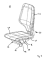
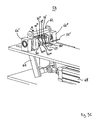
- FIG. 1 shows an exemplary embodiment of a seat device in the form of a chair 10.
- the chair 10 is designed as an office swivel chair. It comprises a support column 12, a back part 20, a seat 24 and a support structure 13 according to the invention for the back part 20 and the seat 24.
- the support structure 13 holds the back part 20 and the seat 24 respectively in a basic position, provided that the back part 20 or the seat 24 no load acts, and allows the back member 20 and the seat 24 can be deflected from the respective basic position, if a load acts on the back part or the seat 24.
- the back part 20 and the seat 24 unloaded and are therefore in the respective basic position. In this basic position, the backrest 22 is substantially vertical and the seat 24 is oriented substantially horizontally.
- the support structure includes, inter alia, a base support 14, which in the present example at an upper end of the support column 12 (optionally rotatable about a vertical axis and height adjustable) is arranged, and a support member 16.
- a base support 14 which in the present example at an upper end of the support column 12 (optionally rotatable about a vertical axis and height adjustable) is arranged, and a support member 16.
- One end of this support member 16 is rigid with a bearing shaft 18th connected, which is mounted on the base support 14 such that it is rotatable about its longitudinal direction.
- the support member 16 is therefore rotatable together with the bearing shaft 18 and thus pivotally mounted on the base support 14.
- the base support 14 further serves as a housing for accommodating mechanical elements, which will be described below, in particular in connection with the Fig. 2-10 ,
- the back part 20 comprises a backrest 22 and a connecting piece 21, which is formed as an angle profile, wherein the backrest 22 is fixed to one leg of this angle profile and the other leg of this angle profile for attachment of the back portion 20 to the support member 16 is used.
- the support member 16 at the end remote from the bearing shaft 18 a channel with an adapted to the outer contour of the connecting piece 21 opening, wherein the remote from the backrest 22 end of the connecting piece 21 can be inserted into this channel and then along this channel can be brought into a position relative to the support member 16, in which the connector 21 (with means not shown in the figures) on the support member 16 can be fixed.
- the back part 20 Fixed on the support part (as in Fig. 1 shown), the back part 20 is therefore rigidly coupled via the support member 16 to the bearing shaft 18 and thus pivotally mounted on the base support 14.
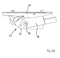
- the seat 24 rests on a seat support 28, which in the present case is pivotable about a pivot axis which is fastened on the support part 16 (as in FIG Fig. 3A is indicated).
- the seat support 28 is thus supported on the support part 16 at least in a partial area. Another portion of the seat support 28 may be supported on the base support 14.
- the support structure 13 additionally comprises a (in Fig. 1 Not shown) force system which generates a restoring force or a restoring torque, which restoring force acts on the support member 16 and which restoring force between the support member 16 and the base support 14 and a movement of the support member 16 relative to the in Fig. 1 counteracts the illustrated basic position.
- a force system will be described below in connection with Fig. 2-10 explained in more detail.
- the support part 16 accordingly carries the back part 20 and the seat 24 and holds the back part 20 and the seat 24 in a position which depends on the relative position of the support part 16 with respect to the base support 14.
- Fig. 2 shows in a perspective view of the support structure 13 according to Fig. 1 including the base support 14 and the support member 16 and the seat support 28, wherein the back part 22 and the seat 24 is removed and accordingly in Fig. 2 are not shown.
- the bearing shaft 18 is positively connected via a attached to the support member 16 extension piece 26 rotatably connected to the support member 16.
- the seat support 28 is arranged, on which in turn the in Fig. 1 shown seat 24 can be attached.
- the carrier part 16 assumes in the present example, the basic position and, starting from this basic position in a clockwise direction (relative to the in Fig. 2 shown perspective) are pivoted about the longitudinal direction of the bearing shaft 18.
- the seat carrier 28 may be related to Fig. 1 described mechanical coupling
- the base support 14 is formed like a box and includes, for example, a force system 30 for generating a restoring force or a restoring torque, which restoring force on the support member 16 and which restoring torque between the support member 16 and the base support 14 acts and a movement of the support member 16 relative to the base support 14th is opposite.
- FIG. 3A and 3B each show the in FIG. 2 illustrated support structure 13 in a side view, wherein the base support 14 both in Fig. 3A as well as in Fig. 3B each assumes the same position in space.
- FIG. 3A shows the support structure 13 in a state in which the support member 16 is in the normal position.
- FIG. 3B shows the support structure 13 in a state in which the support member 16 is deflected from the basic position, that is rotated or pivoted clockwise relative to the basic position.
- FIG. 3B shown state adjusts as soon as a seated on the chair 10 person leans against the backrest 22 and thereby exerts a force on the backrest 22 and thus on the back support 16 so that the backrest 22 and thus the back support 16 performs a pivoting movement.
- the seat support 28 moves relative to the base support 14 (in comparison to the situation according to Fig. 3A ).
- the in FIG. 1 Seat 24 shown under the circumstances also moves synchronously with the backrest 22.
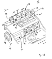
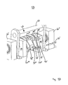
- FIGS. 4A and 4B show the in FIG. 2 In order to make details of the base support 14 and the power system 30 better recognizable, the support member 16 and the seat support 28 in Fig. 4A and 4B not shown.
- the force system 30 comprises a plurality of spring elements for generating a restoring force: in the present example, a "first" spring element 32 and three “second” spring elements 33 ', 33 “and 33”'.
- the spring elements 32, 33 ', 33 "and 33"' are each in the form of an elastomer Torsionsfederelements whose structure and operation hereinafter - especially in connection with Fig. 7A - Is described in more detail.
- first spring element 32 and the second spring elements 33 ', 33 "and 33"' respectively - as in Fig. 7A an inner housing 43, an outer housing 44 surrounding the inner housing 43, and an elastomeric body 46 arranged in an intermediate space between the inner housing 43 and the outer housing 44, the elastomeric body 46 being connected both to the inner housing 43 and to the outer housing 44 are firmly connected.
- the elastomeric body 46 is elastically deformed if the inner housing 43 is moved relative to the outer housing 44, and then generates between the inner housing 43 and the outer housing 44, a restoring force, which counteracts this movement. Accordingly, a restoring torque is generated between the inner housing 43 and the outer housing 44 if the inner housing 43 is rotated relative to the outer housing 44.
- the inner housing 43 of each of the spring elements 32, 33 ', 33 “and 33”' has a continuous channel whose cross section is formed such that the bearing shaft 18 through this channel is feasible and each of the spring elements 32, 33 ', 33 “and 33 “'can be plugged onto the bearing shaft 18 such that the respective inner housing 43 of each of the Spring elements 32, 33 ', 33 “and 33”' is positively connected to the bearing shaft 18 and is seated on the bearing shaft 18 such that the respective inner housing 43 is rotationally rigidly connected to the bearing shaft 18.
- the first spring element 32 of the power system 30 is coupled to both the base support 14 and the support member 16 in the following manner: a first portion of the spring member 32, ie, the inner housing 43 of the first spring member 32, is rotationally rigid with the first Bearing shaft 18 is connected and therefore rigidly coupled to the bearing shaft 18 and thus also to the support member 16 so that upon pivotal movement of the support member 16, the inner housing 18 is rotated about the axis of rotation of the bearing shaft 18; Furthermore, a second portion of the spring element 32, the outer housing 44 of the first spring element 32, rigidly connected to the base support 14 (which Fig. 4A and 4B is not apparent, but from the representation of the force system 30 in Fig. 5B is recognizable).
- the bearing shaft 18 and the inner housing 43 of the first spring member 32 are rotated together about the axis of rotation (longitudinal axis) of the bearing shaft 18, while the outer housing 44 is stationary with respect to the base support 14 is positioned. Accordingly, the inner housing 43 and the outer housing 44 of the first spring element 32 are rotated during a pivoting movement of the support member 16 relative to each other. Accordingly, while the elastomeric body 46 of the first spring member 32 is elastically deformed, so that the first spring member 32 a on the bearing shaft 18 and the Support member 16 generates acting restoring torque, which counteracts the pivotal movement of the support member 16.
- the power system 30 offers the possibility of bringing the second spring elements 33 ', 33 "and 33"' into a state (hereinafter referred to as “coupled state”) in which the respective spring element 33 ', 33 “or 33 '' to the base support 14 and the support member 16 is coupled, and further in another state (hereinafter “uncoupled state” called to bring), in which the respective second spring element 33 ', 33 “or 33”' not to the base support and / or the carrier part is coupled.
- the power system 30 comprises a coupling mechanism 34 for coupling the respective second spring element 33 ', 33 “or 33” to the base support 14 and / or the support part 16.
- the coupling mechanism 34 is fixed to the base support 13 and may (as hereinafter be explained) are brought into different states in which the coupling mechanism 34 optionally with the respective second spring element 33 ', 33 “or 33”' cooperates such that the respective second spring element 33 ', 33 “or 33”' in the coupled Condition is and in this state is able to generate a force acting on the support member 16 restoring force, or cooperates such that the respective spring element 33 ', 33 "or 33”' is in the uncoupled state and in this state in a position is to produce a force acting on the support member 16 restoring force.
- the first holding means 36 'for holding the outer housing 44 of the second spring element 36' is in the form of a movable part, which is attached to the base support 14 and (as will be explained in more detail below) on the one hand in a "first" position can be brought, in which the holding means 36 'is brought into contact with the outer housing 44 of the second spring element 33' and holds the outer housing 44 in a predetermined position relative to the base support 14, and on the other hand in a "second" position can be brought, in which the holding means 36 'not with the outer housing 44 of the outer housing 44 is in contact.
- first holding means 36 ' is a means for releasably holding the outer housing 44 of the second spring element 36', wherein the outer housing 44 is held by the first holding means 36 'only when the holding means 36' is in said first position , and the outer housing 44 separated from the first holding means 36 '(released) is, if the first holding means 36 'is in the second position.
- the above-mentioned 'coupling device' associated with the second spring element 33 ' has the property that when the first retaining means 36' is brought into said first position, the outer housing 44 of the second spring element 33 'is connected to the base support 14 and the inner housing 43 of the second spring elements 33 'is rigidly connected to the bearing shaft 18 and thus rigidly connected to the support member 16. In this case, the second spring element 33 'is in the already mentioned coupled state. If, however, the first holding means 36 'brought into said second position, the outer housing 44 of the second spring element 33' is not connected to the base support 14.
- the first spring element 33 ' is in the uncoupled state: in this case, the second spring element 33' is rotated together with the bearing shaft 18 when the bearing shaft 18 rotates about its longitudinal direction as a whole, with the inner housing 43 of the second spring element 33 '. is not rotated relative to the outer housing 44 and the elastomeric body 46 of the second spring element 33 'is not deformed. Accordingly, the second spring element 33 ', if the first holding means 36' is in the second position, generate on a pivoting movement of the support member 16 does not act on the support member 16 restoring force, which counteracts this pivotal movement.
- Coupled means of the coupling mechanism 34 associated with the respective second spring members 33 “and 33”' are constructed in structure and function analogous to that of the coupling means previously described in connection with the second spring member 33'. Accordingly includes the coupling mechanism 34 (analogous to the first holding means 36 ') a first holding means 36 “for releasably holding the outer housing 44 of the second spring element 33” and a first holding means 36''' for releasably holding the outer housing 44 of the second spring element 33 '''.
- the coupling mechanism 34 further comprises (analogous to the mentioned second holding means for the second spring element 33 ') a second holding means for holding the inner casing 43 of the spring element 33' (realized in the form of the already mentioned positive connection between the inner casing 43 of the spring element 33 "and the bearing shaft 18) and a second holding means for holding the inner housing 43 of the spring element 33 '''(realized in the form of the already mentioned positive connection between the inner housing 43 of the spring element 33''' and the bearing shaft 18)
- first holding means 36 ', 36 "and 36''' are arranged side by side in a row such that they are pivotable about a pivot axis 37 which is aligned parallel to the bearing shaft 18 and stationary relative to the base support 14 is arranged first holding means 36 ', 36 "and 36"' are each pivotable about the pivot axis 37 such that they can be selectively brought into contact with the outer housing 44 of the respective associated spring element 33 ', 33''and33''' (in the first position of the respective holding means) or are separable from the respective outer housing (in the second position of the respective holding means).
- the support structure 13 comprises an actuating means 38 for moving the respective first holding means 36 ', 36 "' and 36 '".
- the actuating means 38 in the present example comprise a rotatable camshaft 39, on the cams 40', 40 "and 40 '' are arranged, which in each case (in this order) one the first holding means 36 ', 36 "and 36"' are assigned.
- the cams 40 ', 40 "and 40”' are shaped such that upon rotation of the camshaft 39 (about the longitudinal axis of the camshaft 39) they drive the first holding means 36 ', 36 “and 36'” individually or in combination with one another to pivot the first holding means 36 ', 36 “and 36''' respectively about the pivot axis 37 and optionally with the outer housing 44 of the respectively associated second spring element 33 '. 33 '' and 33 '''to bring into contact.
- Fig. 4A and 4B show the camshaft 39 in a position in which the respective cams 40 ', 40 "and 40"' are arranged such that all the first holding means 36 ', 36 “and 36''' are arranged such that none of the holding means 36 ' , 36 '' and 36 '''in contact with one of the second spring elements 33', 33 "and 33 '''is brought. Accordingly, in this case, only the first spring element 32 is coupled both to the base support 14 and to the support part 16.
- all second spring elements 33 ', 33 "and 33'” are in the uncoupled state a pivoting movement of the support member 16 or at a corresponding rotation of the bearing shaft 18 exclusively the first spring element 32 acting on the bearing shaft 18 and the support member 16 restoring torque, which counteracts the pivotal movement of the support member 16 and the rotation of the bearing shaft 18.
- FIG. 4B shows the in FIG. 4A illustrated coupling mechanism 34 from a different perspective.
- outer housing cams 42 '- 42''' can be seen, which are each attached to the outer housings 44 of the second spring elements 33'-33 '''or formed.
- outer housing cams 42 '- 42''' are arranged such that in each case that first holding means 36'-36 "', which by a corresponding Actuation of the actuating means 38 is brought into the first position, is brought into contact with the corresponding outer housing cam 42 '-42'”and forms a mechanical stop for this outer housing cam.
- first holding means 36'-36 "' which by a corresponding Actuation of the actuating means 38 is brought into the first position
- Fig.5A - 5C 14 show a detailed view of the support structure 13, wherein the spring elements 32, 33 ', 33 "and 33"' and the coupling mechanism 34 of the force system 30 are shown in different states Fig. 5A - 5c not shown (to clarify the facts presented).
- Such rotation for example, by a on the seat assembly 10 according Fig. 1 seated person are caused when leaning back against the backrest 22.
- Upon rotation of the bearing shaft 18 in the direction of the arrow 18 ' would only the first spring element 32 generate a restoring torque acting on the bearing shaft 18 (corresponding to the in Fig. 4A and 4B illustrated situation).
- Fig. 5B represents a state of the force system 30, which differs from the in Fig. 5A illustrated state in that the first holding means 36 '''is now in the first position (and accordingly with the in Fig. 5B and the bearing shaft 18 is rotated counterclockwise (ie, in the direction of the arrow 18 ') by a certain rotational angle in a state in which the second spring element 33 '''is in the coupled state and the second spring elements 33' and 33 "are in the uncoupled state.
- Fig. 5A shows is in the state according to Fig. 5B the spatial position of the outer housing of the first spring element 32 and the spatial position of the outer housing of the second spring element 32 '''unchanged (in comparison to the situation Fig.
- FIG. 5C shows a state dese power system 30 and the coupling mechanism 34, in which all the second spring elements 33'-33 "'are in the coupled state:
- the cams 40'-40''' are aligned by a suitable rotation of the camshaft 39 such that the first holding means 36'-36 '''are in the first position and are thus brought into contact with the outer housing cams 42' - 42 '' of the second spring elements 33'-33 '''.
- a (total) restoring torque which corresponds to the sum of all restoring torques generated by those spring elements 32, 33'-33 '", which are in each case in the coupled state and thus both acts on the bearing shaft 18 are coupled to the base support 14 and to the support member 16. Since in the in Fig. 5A shown state of the power system 30, only the first spring element 32 is in the coupled state, generates the power system 30 in the state according to Fig. 5A upon rotation of the bearing shaft 18 by a predetermined rotation angle ⁇ a reset torque with the lowest possible value and is therefore in this state tuned to persons with a relatively low body weight. Since in the in Fig.
- the power system 30 generates in the state according to Fig. 5C during a rotation of the bearing shaft 18 by the same (above-mentioned) rotation angle ⁇ a reset torque with the largest possible value and is therefore tuned in this state to persons with a relatively large body weight. Accordingly, the power system 30 generates in the state according to Fig. 5B upon rotation of the bearing shaft 18 by the same (above-mentioned) rotation angle ⁇ , a restoring torque whose value lies between the corresponding values of the restoring torque which the force system 30 in the states according to FIG Fig. 5A and 5C generated, and is therefore tuned to persons with a medium body weight.
- Fig. 6A and 6B show a schematic view of the power system 30 together with the coupling mechanism 34 and actuating means 38, wherein the base support 14 is not shown to detail the individual spring elements 32, 33'-33 "'(in particular their outer contours and their arrangement on the bearing shaft 18)
- the camshaft 39 is rotated such that the cams 40'-40 "'are positioned so that only the first holding means 36' is brought into the first position and thus (apart from the first spring element 32) only the second spring element 33 ' is in the coupled state.
- Fig. 6B shows the coupling mechanism 34 in a state in which none of the second spring members 33'-33 "'is set in the coupled state Fig. 6B The situation shown is therefore identical to that in Fig. 5A illustrated situation.
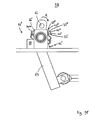
- FIG. 7A shows a schematic side view of the second Spring element 33 'in a plane perpendicular to a rotation axis 47 cutting plane.
- the spring elements 32, 33 'and 33 are identical in terms of their structural design with the spring element 33', so that in the following the properties of the spring elements 32 and 33'-33" based on the spring element 33 'according to Fig. 7A should be explained.
- the spring element 33 ' (as the spring elements 32, 33' and 33 ") is designed as an elastomer torsion spring element and comprises an inner housing 43 and an outer housing 44. In a space between the inner housing 43 and the outer housing 44 is a Elastomer body 46 is arranged.
- the inner housing 43 has on its outer side a contact surface 43 a, on which the elastomeric body 46 is in contact with the inner housing 43. Furthermore, the outer housing 44 has on its inside a contact surface 44a, on which the elastomeric body 46 is in contact with the outer housing 44.
- the contact surface 43a of the inner housing 43 and the contact surface 44a of the outer housing 44 enclose the axis of rotation 47 in each case in an annular manner. Accordingly, the elastomeric body 46 in the present example forms a closed ring surrounding the axis of rotation 47.
- the elastomeric body 46 is made of an elastomer, ie a solid and elastically deformable material.
- the elastomeric body 46 is formed such that it is fixedly connected to the contact surface 43 a of the inner housing 43 and the contact surface 44 a of the outer housing 44, ie upon movement of the inner housing 43 relative to the outer housing 44 (eg upon rotation of the inner housing 43 or Outer housing 44 about the axis of rotation 47) there is no displacement of the contact surfaces 43a and 44a adjacent surfaces of the elastomeric body 46 relative to the contact surfaces 43a and 44a instead.
- the elastomeric body 46 may, for example, material-fit or positive fit to the contact surfaces 43a and 44a to be connected to the inner housing 43 and the outer housing 44.
- a particularly well-suited for the production of the elastomeric body 46 elastomer is for example rubber, which is not only an elastically deformable and high-strength material, but also in a simple manner with the contact surfaces 43a and 44a can be firmly connected, for example by means of vulcanization.
- the inner housing 43 and the outer housing 44 are made of a solid material, such as steel.
- the respectively adjacent to the elastomer body 46 contact surfaces 43a and 44a of the inner housing 43 and the outer housing 44 differ - in a plane perpendicular to the axis of rotation 47 cutting plane - at least partially from a circular shape.
- pressure loads occur which compensate for tensile loads therein.
- the elastomeric body 46 is loaded non-homogeneously.
- Fig. 7A For example, the inner casing 43 is shown in a "non-rotated" state (solid line) and a “twisted state” (broken line), and the inner casing 43 is rotated about the rotation axis 47 in a twisted state as compared with the untwisted state by a rotation angle ⁇ in a clockwise direction is while the position of the outer housing 44 remains unchanged. It is assumed that the elastomeric body 46 is not biased in the case of the untwisted state, ie has no mechanical stresses. In the untwisted state, the distances from the upper right corner and the lower left corner of the inner housing 43 to respectively defined points on the inside of the outer housing 44 are shown with arrows x1 and y1, respectively.
- the distances from the upper right corner and the lower left corner of the inner housing 43 to respectively defined points on the inner side of the outer housing 44 are indicated by arrows x2 and y2, respectively.
- the distance x2 is less than x1 and the distance y2 is less than y1.
- the elastomeric body 46 is compressed when the inner housing 43 is rotated about the rotation axis 47 and thereby rotated relative to the outer housing 44. From these respective compressions result the above-mentioned pressure loads.
- the contact surface 43a of the inner housing 43 adjoining the elastomeric body 46 is square-shaped.
- the inner housing 43 is formed as a square sleeve (square), which has a parallel to the axis of rotation 47 extending, continuous channel 43.1 with a square cross-section.
- the shape of the cross section of the channel 43.1 is adapted to the cross-sectional shape of the bearing shaft 18, so that the bearing shaft 18 inserted through the channel 43.1 and the inner housing 43 - positively connected to the bearing shaft 18 - can sit on the bearing shaft (as already in connection with Fig. 4A and 4B mentioned).
- the adjacent to the elastomeric body 46 contact surface 44a of the outer housing 44 has a contour which is to be regarded as a combination of a rectangle and a circle. More specifically, the contour of the outer casing 44 is composed of two paired opposite isosceles angular segments, which in the present example enclose an angle of 90 °, and of two pairwise opposed semicircular segments whose ends are respectively connected to the ends of said angle segments.
- this "lemon-shaped" contour of the outer housing 44 in combination with the square contour of the inner housing 43, is particularly advantageous to provide an elastomeric torsion spring element whose characteristic of the restoring torque D in relation to Rotation angle ⁇ is linear in almost all areas of the rotation angle ⁇ .
- Fig. 7A further shows the exterior housing 44 formed on the outer housing cam 42 ', which already in connection with Fig. 4B and 5A-5C was mentioned.
- Fig. 7B shows that in Fig. 7A illustrated spring element 33 'with a holding element 48 in a perspective view.
- the holding element 48 serves to hold the inner housing 43 and the outer housing 44 in a "home position" relative to each other, in which the elastomeric body 46 has a mechanical stress (preload) and thus between the inner housing 43 and the outer housing 44, a restoring torque D. generated, which is different from zero.
- the inner housing 43 is opposite to the "unrotated" position (without bias) according to Fig. 7A by a rotational angle ⁇ (hereinafter referred to as "biasing angle") rotated, with respect to Fig. 7A clockwise and in terms of Fig. 7B in the counterclockwise direction.
- the holding element 48 contains in this example two clamping elements 49, which are each plugged onto one of the end faces of the spring element 33 '.
- the clamping element 49 is a substantially flat plate which is punched out in the center region in such a way that two opposite flanges 50 ', 50 "are left behind, these flanges being bent in each case by 90 ° inwards (into the plane of the figure) 49 tabs 52 ', 52' 'are formed, which are also bent by 90 ° inwards.
- the flanges 49 which are designed such that their outer regions are positively connected to the inner surface of the inner housing 43, to a first Distance plugged into the inner housing 43. Then, the clamping element 49 and thus radially positively connected to the inner housing 43, in a fixed outer housing 44, counterclockwise rotated by a certain angle (for example, 20 °) in relation to the outer housing 44.
- the clamping element 49 is pressed with its flanges 50 ', 50' 'completely into the channel 43.1 of the inner housing 43, wherein at the same time the tabs 52', 52 '' occupy a positive connection with the outer surface of the outer housing 44.
- the clamping element 49 maintains the bias. More precisely, the pretensioning angle ⁇ can no longer be undershot, since the tabs 52 ', 52 "abut against the outer surface of the outer housing 44. However, an increase in the rotational offset (also counterclockwise) between the inner housing 43 and the outer housing 44 is possible.
- the clamping element 49 can also in combination with the spring elements 32, 33 'and 33''analogous to that in Fig. 7B example used can be used. It should be noted that in the case of the power system 30 in the illustrations according to Fig. 4A . 4B , 5a 5C . 6A and FIG. 6b shows the respective second spring elements 33 ', 33 "and 33''' respectively in combination with two tensioning elements which correspond to the tensioning elements 49 Fig. 7B correspond (as in particular Fig. 6A and 6B hint).
- each of the second spring elements 33 ', 33 "and 33"' of the power system 30 generates upon rotation of the bearing shaft 18 each acting on a bearing shaft 18 restoring torque, which is greater than or equal to a predetermined (non-zero) minimum value, if the respective second spring element 33 ', 33 "or 33"' is in the coupled state.
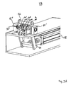
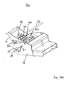
- Figures 8A-8C show (in different views) a variant of the force system 30 according to Figs. 3A-6B , which differs from the force system 30 according to Figs. 3A-6B essentially differs in that it (as a substitute for clamping elements in the manner of the clamping element 49 according to Fig. 7B ) Clamping elements 54 ', 54'', 54 "' and 54 '''', which in terms of their construction of the clamping elements 49 according to Fig. 7B differ.
- the variant of the power system 30 according to Figs. 8A-8C accordingly comprises (as the force system 30 according to Figs. 3A-6B ) also the bearing shaft 18, the first spring element 32 and the second spring elements 33 ', 33 "and 33"'.
- the coupling mechanism 34 and the actuating means 38 are in FIG Figs. 8A-8C not shown.
- the clamping elements 54'-54 "" are plate-like elements whose inner areas are punched rectangular. Here, the contour of the punched form fit to the outer contour of the (square) bearing shaft 18 is adjusted. At the outer regions of the clamping elements 54'-54 “” vaults 55'-55 "” are formed, each containing a vertical through hole.
- the bearing shaft 18 and the inner housing of the first spring element 32 are connected to each other in a radially form-fitting manner.
- all three second spring elements 33'-33"'with respectively interposed clamping elements 54'-54 "' are placed on the bearing shaft 18, is finally the last clamping element 54 '''' frontally attached.
- the second spring elements 33'-33 "'either individually or simultaneously biased by, for example, their outer housing, with radially fixed bearing shaft 18, are rotated in a clockwise direction about the longitudinal direction of the bearing shaft 18. This rotation takes place up to a rotational angle at which pins 56 ', 56 "through the respective holes of the bulges 55'-55" "can be inserted therethrough.
- the introduction of force for turning the outer casings is terminated, in which state the outer casings of the individual second spring elements 33'-33"' remain in this position, since the respective outer surfaces of the outer casings are now against a peripheral portion of the pins 56 ', 56 "abuts. Thus, it is no longer possible that the respective outer housing is rotated back to the initial state.
- Figs. 9A-9E show different views of a tensioning device 58 for biasing in the Figures 8A-8C shown spring elements 33'-33 "'with the intermediate and frontally mounted clamping elements 54'-54""
- Fig. 9A and 9C the tensioning device 58 is shown in a full view, viewed from different directions.
- Fig. 9B and 9D the tensioning device 58 is shown in a detail view, viewed from different directions.
- the clamping device 58 is used for easy and fast preloading of the individual spring elements 32'-32 '''with only a few steps.
- the tensioning device 58 contains fixing devices 60, which the bearing shaft 18 (not shown) fixedly clamped at their axial ends.
- the tensioning device 58 further includes a rod 62 which is perpendicularly connected between two lever arms of a lever 64.
- the lever arms are pivotally hinged via jig bearings 66 ', 66 ".
- the lever 64 is deflectable back and forth at its lower end by a drive 68.
- the rod 62 Upon deflection of the lower portion of the lever 64 in a direction out of the plane of the figure Fig. 9A out, the rod 62 is deflected toward the spring elements 33'-33 '", as indicated by an arrow A.
- a further surface region of the rod 62 engages with the outer surface of the outer housing of a further spring element, in this example with the outer housing of the spring element 33 ''
- the previously brought into engagement outer surface of the outer housing of the spring element 33 "'is pivoted or rotated.
- a region of the outer surface of the outer housing of a further spring element in this example the outer housing of the spring element 33 ', is engaged.
- Figure 9E shows the tensioning device 58 in a view viewed axially with respect to the tensioning device bearings 66 ', 66 ". It can be seen particularly clearly in this figure that the individual spring elements 33'-33"' are each deflected differently in their initial state. This is due to the fact that the respective inner housings of the spring elements 33'-33 "'are arranged in each case with a rotational offset in relation to the contour of their respective outer housings, which is in each case of different size for the spring elements 33'-33"'. The rotational offsets can for the spring elements 33'-33 "'example 20 °, 25 ° and 40 °.
- the individual spring elements 33'-33 are thus biased to different degrees, thus forcing the spring element 33"'stronger than the spring element 33 ", which in turn is more strongly biased is used as the spring element 33 ' FIGS. 9A and 9C-9E
- the pins 56 ', 56 can be inserted through the bores of the bulges 55' - 55 1 ""of the respective clamping elements 54 '- 54""after pretensioning, thus making the respective prestressing of the individual spring elements 33'-33 '' by the pins 56 ', 56 "maintained.
- Fig. 10A shows a support structure according to the invention 13a, which a variant of the support structure 13 according to Fig. 2 represents.
- Those components which have the support structures 13A and 13B in common are referred to below with the same reference numerals.
- the support structure 13a according to Fig. 10A comprises - as the support structure 13 according to Fig. 2 - A base support 14 and a support member 16 (for supporting and / or holding the back part 20 and / or the respective seat 24 according to Fig. 1 ).
- the support member 16 is rotationally rigidly connected via an extension piece 26 to the ends of a rotatable bearing shaft 18, so that the support member 16 about the longitudinal axis of the bearing shaft 18 in the direction of the arrow 18 'is pivotable.
- the Fig. 10B also shows the support structure 13A according to Fig. 10A , with the only difference being that in the Fig. 10B the carrier part 16 is not shown.
- the support structure 13a comprises a force system 30a which comprises two first spring elements 32a and second spring elements 33 ', 33 "and 33"'.
- the spring elements 32a, 33 ', 33 "and 33"' are each designed as an elastomer torsion spring element and are identical in terms of their structure with the spring element 33 'according to Fig. 7A ie they each have an inner housing 43, an outer housing 44 surrounding the inner housing 43 and an elastomeric body 46 arranged in an intermediate space between the inner housing 43 and the outer housing 44, which is fixedly connected to the inner housing 43 and the outer housing 44.
- the second spring elements 33 ', 33 "and 33"' of the power system 30a are identical to the spring elements 33 ', 33 "and 33"' of the power system 30.
- the first spring element 32a of the power system 30a differs from the first spring element 32 of the force system 30 in its construction substantially by the shape of the cross section of the outer housing 44. The latter, however, with regard to Function of the first spring element 32a in this context is not important.
- Fig. 10B indicates, sit the spring elements 32a, 33 ', 33 "and 33"' of the power system 30a on the bearing shaft 18 such that the inner housing 43 of the spring elements are each rotationally rigidly connected to the bearing shaft 18.
- the outer housing 44 of the respective first spring element 32a is rigidly connected to the base support 14, while the inner housing 43 together with the bearing shaft 18 in the direction of the arrow 18 'can be rotated.
- the two first spring elements 32a are accordingly coupled in the sense of the invention both to the base support 14 and to the support member 16, so that the first spring elements 32a in a pivotal movement of the support member 16 in the direction of arrow 18 'each generate a restoring torque, which the pivoting movement of the Support member 16 is directed opposite.
- the second spring elements 33 ', 33 "and 33”' of the power system 33a functionally correspond to the second spring elements 33 ', 33 "and 33”' of the power system 30.
- the support structure 13a also includes the same coupling mechanism 34 and the actuating means 38 for controlling the coupling mechanism in that the respective second spring elements 33 ', 33 “and 33”' are selectively in the coupled state (in which the respective spring element 33 ', 33 “and 33”' via the coupling mechanism 34 both to the base support 14 and to the support member 16th is coupled) or in the uncoupled state (in which the respective spring element 33 ', 33 " 1 and 33"' is not coupled to the base support 14 and / or to the support member 16) can be brought.
- a significant feature of the power system 13a is the fact that the support member 16 and the two ends of the Bearing shaft 18 are always coupled via the elastomeric body 46 of the two first spring elements 32a to the base support 14, wherein the elastomeric body 46 can receive a radially acting on the bearing shaft 18 load.
- the bearing shaft 18 does not require a separate pivot bearing, which rotatably supports the bearing shaft 18 on the base support 14.
- the first spring elements 32a serve as a bearing for the bearing shaft 18, in particular when none of the second spring elements 33'-33 "'is switched to the coupled state Condition is also used this spring element as a bearing for the bearing shaft 18 with respect to the base support fourteenth
- the spring elements 32a thus exert a double function: as a means for generating a force acting on the support member 16 restoring force and as a bearing for the storage of the bearing shaft 18.
Landscapes
- Health & Medical Sciences (AREA)
- Dentistry (AREA)
- General Health & Medical Sciences (AREA)
- Springs (AREA)
- Chairs For Special Purposes, Such As Reclining Chairs (AREA)
- Pivots And Pivotal Connections (AREA)
Description
Die Erfindung bezieht sich auf eine Tragstruktur für ein Rückenteil und/oder einen Sitz einer Sitzeinrichtung und eine Sitzeinrichtung mit einer derartigen Tragstruktur.The invention relates to a support structure for a back part and / or a seat of a seat device and a seat device with such a support structure.
Eine Tragstruktur ist aus
Sitzeinrichtungen, beispielsweise Stühle, sind meist modular aufgebaut: Sie umfassen in der Regel neben einem Sitz und gegebenenfalls einem Rückenteil, welches beispielsweise eine Rückenlehne umfassen kann, auch eine Tragstruktur für das jeweilige Rückenteil und/oder und den jeweiligen Sitz, wobei es die Aufgabe der Tragstruktur ist, den Sitz und gegebenenfalls das Rückenteil in einer bestimmten Lage zu halten und eine Last, welche beispielsweise von einer auf der Sitzeinrichtung sitzenden Person auf den Sitz bzw. das Rückenteil übertragen werden kann, aufzunehmen und den Sitz und gegebenenfalls das Rückenteil bei Einwirkung der jeweiligen Last jeweils in einer stabilen Lage zu halten.Seat devices, such as chairs, are usually modular: They usually include next to a seat and possibly a back part, which may for example comprise a backrest, also a support structure for the respective back and / or and the respective seat, wherein it is the task of Tragstruktur is to hold the seat and possibly the back part in a certain position and a load, which can be transmitted, for example, from a person sitting on the seat on the seat or the back, and the seat and possibly the back part under the action of each load to be kept in a stable position.
Sitzeinrichtungen sind häufig nicht starr ausgebildet. Häufig ist jeweilige Tragstruktur so konstruiert, dass die Tragstruktur zwar ortsfest im Raum platziert werden kann, die räumliche Lage des jeweiligen Rückenteils und/oder des jeweiligen Sitzes relativ zur Tragstruktur veränderbar ist. Dies bietet beispielsweise die Möglichkeit, dass einerseits die räumliche Anordnung des Rückenteils und/oder des Sitzes an die jeweilige Körperhaltung einer auf der jeweiligen Sitzeinrichtung sitzenden, ihre Körperhaltung ständig ändernde Person angepasst werden kann, oder um beispielsweise zu erreichen, dass dieselbe Sitzeinrichtung auf unterschiedliche Bedürfnisse verschiedener Personen, welche sich beispielsweise hinsichtlich der Körpergrösse oder des Körpergewichts oder ihrer bevorzugten Körperhaltung beim Sitzen unterscheiden können, abgestimmt werden kann. Zu diesem Zweck umfasst eine konventionelle Tragstruktur einer Sitzeinrichtung in der Regel einen Basisträger, welcher beispielsweise ortfest im Raum platziert werden kann, und mindestens ein am Basisträger angeordnetes Trägerteil, welches Trägerteil derart am Basisträger befestigt ist, dass eine Bewegung des Trägerteils relativ zum Basisträger ausführbar ist, und welches Trägerteil dazu bestimmt ist, das Rückenteil und/oder den Sitz in einer Position zu halten, welche von der relativen Lage des Trägerteils bezüglich des Basisträgers abhängig ist. Dabei muss das Rückenteil bzw. der Sitz nicht unmittelbar an dem Trägerteil befestigt sein: das Rückenteil bzw. der Sitz können jeweils über ein oder mehrere andere Komponenten mit dem genannten Trägerteil verbunden oder an das Trägerteil gekoppelt sein.Seat devices are often not rigid. Frequently, respective support structure is constructed so that the support structure can indeed be placed in the space stationary, the spatial position of the respective back part and / or the respective seat is variable relative to the support structure. This provides, for example, the possibility that on the one hand the spatial arrangement of the back and / or seat to the respective posture of sitting on the respective seat device, their posture constantly changing person can be adjusted, or to achieve, for example, that the same seat device to different needs different people, which, for example, in terms of body size or body weight or their preferred posture while sitting, can be matched. For this purpose, a conventional support structure of a seat device usually comprises a base support, which can be placed, for example, stationary in space, and at least one arranged on the base support member, which support member is fixed to the base support such that movement of the support member relative to the base support executable , And which support part is intended to hold the back part and / or the seat in a position which is dependent on the relative position of the support member relative to the base support. In this case, the back part or the seat does not have to be fastened directly to the carrier part: the back part or the seat can each be connected via one or more other components to said carrier part or coupled to the carrier part.
Eine Tragstruktur der vorstehend genannten Art kann auch mit einem Kraftsystem zur Erzeugung mindestens einer Rückstellkraft, welche bei der jeweiligen Bewegung des Trägerteils erzeugt wird und dieser Bewegung entgegengerichtet ist, ausgestattet sein. Beispielsweise kann ein derartiges Kraftsystem ein oder mehrere Federelemente umfassen, welche jeweils derart an den Basisträger und das Trägerteil gekoppelt sind, dass das Federelement bei der jeweiligen Bewegung des Trägerteils eine Rückstellkraft erzeugt, welche der jeweiligen Bewegung des Trägerteils entgegengerichtet ist. Ein derartiges Kraftsystem gewährleistet eine nachgiebige Anordnung des Rückenteils bzw. des Sitzes, derart, dass das jeweilige Rückenteil und/oder der jeweilige Sitz gegebenenfalls bei Einwirkung einer Kraft aus einer vorgegebenen Gleichgewichtslage ausgelenkt werden, wobei gleichzeitig das Trägerteil aus einer vorgegebenen Gleichgewichtslage ausgelenkt und eine der Auslenkung des Trägerteils entgegen wirkende Rückstellkraft erzeugt wird. Die jeweilige Rückstellkraft ist dabei in der Regel umso grösser, je weiter das Trägerteil aus der ursprünglichen Gleichgewichtslage ausgelenkt ist. Dadurch, dass das Kraftsystem eine Rückstellkraft erzeugt, welche der jeweiligen Bewegung des Trägerteils entgegengerichtet ist, kann das Trägerteil anschliessend eine neue Gleichgewichtslage einnehmen, sobald alle auf das Trägerteil wirkenden Kräfte einander kompensieren. Auf diese Weise können das Rückenteil bzw. der Sitz jeweils in einer Gleichgewichtslage gehalten werden, welche von der jeweiligen Belastung des Rückenteils bzw. des Sitzes abhängt. Letzteres sorgt für einen hohen Sitzkomfort, zumal das Rückenteil und/oder der Sitz sich jeweils an die momentane Körperhaltung einer auf der Sitzeinrichtung sitzenden Person anpassen können und die jeweils von dem Kraftsystem erzeugte Rückstellkraft jeweils stützend auf die sitzende Person wirkt.A support structure of the aforementioned type can also be equipped with a force system for generating at least one restoring force, which is generated during the respective movement of the support part and directed counter to this movement. For example, such a power system may comprise one or more spring elements, which are respectively coupled to the base support and the support member, that the spring element generates a restoring force during the respective movement of the support member, which is opposite to the respective movement of the support member. Such a force system ensures a resilient arrangement of the back part or the seat, such that the respective back part and / or the respective seat are optionally deflected upon application of force from a predetermined equilibrium position, at the same time the support member deflected from a predetermined equilibrium position and one of Deflection of the support member counteracting restoring force is generated. The respective restoring force is included as a rule, the greater the further the support part is deflected out of the original equilibrium position. The fact that the force system generates a restoring force, which is opposite to the respective movement of the support member, the support member can then assume a new equilibrium position as soon as all forces acting on the support member compensate each other. In this way, the back part or the seat can each be held in an equilibrium position, which depends on the respective load of the back part or the seat. The latter ensures a high level of comfort, especially since the back and / or the seat can each adapt to the current posture of a seated person sitting on the seat and each restoring force generated by the force system each supporting the seated person acts.
Um den Sitzkomfort, welchen ein Kraftsystem der vorstehend genannten Art gewährleistet, noch zu verbessern, kann ein solches Kraftsystem so konzipiert werden, dass die Grösse der Rückstellkraft, welche das Kraftsystem bei einer bestimmten Auslenkung des Trägerteils aus einer vorgegebenen Gleichgewichtslage erzeugt, in einem gewissen Rahmen variierbar ist und je nach Bedarf einstellbar ist. Letzteres erlaubt eine Anpassung des Kraftsystems an unterschiedliche Bedürfnisse. Bei grossen bzw. schweren Personen ist beispielweise in der Regel eine Einstellung des Kraftsystems angemessen, bei welcher das Kraftsystem bei einer vorgegebenen Auslenkung des Trägerteils eine relativ grosse Rückstellkraft erzeugt ("harte" Einstellung des Kraftsystems), während im Falle von kleinen bzw. leichten Personen eher eine Einstellung des Kraftsystems angemessen ist, bei welcher das Kraftsystem bei einer vorgegebenen Auslenkung des Trägerteils eine relativ kleine Rückstellkraft erzeugt ("weiche" Einstellung des Kraftsystems).In order to improve the sitting comfort, which is ensured by a force system of the type mentioned above, such a force system can be designed such that the magnitude of the restoring force, which generates the force system at a certain deflection of the support member from a predetermined equilibrium position, within a certain scope is variable and can be adjusted as needed. The latter allows an adaptation of the power system to different needs. In the case of large or heavy persons, adjustment of the force system is usually appropriate, for example, in which the force system generates a relatively large restoring force for a given deflection of the carrier part ("hard" setting of the force system), while in the case of small or light persons Rather, an adjustment of the power system is appropriate, in which the force system at a given deflection of the support member generates a relatively small restoring force ("soft" setting of the power system).
Aus
Das Kraftsystem der vorstehend genannten Sitzeinrichtung hat verschiedene Nachteile. Das genannte Elastomer-Torsionsfederelement hat den Nachteil, dass das Rückstelldrehmoment, welches bei einer Drehung der genannten Welle um einen bestimmten Drehwinkel erzeugt wird, einen relativ geringen Anstieg als Funktion des jeweiligen Drehwinkels zeigt, insbesondere dann, wenn das Elastomer-Torsionsfederelement nicht oder nur geringfügig vorgespannt ist. Demzufolge muss das Aussengehäuse des Elastomer-Torsionsfederelements um einen relativ grossen Drehwinkel relativ zum Innengehäuse verdreht und der Elastomer-Körper des Elastomer-Torsionsfederelements relativ stark vorgespannt werden, wenn ein grosses Mindest-Rückstelldrehmoment eingestellt werden soll, um z.B. Personen mit hohem Gewicht einen angemessenen Sitzkomfort bieten zu können. Beim Verdrehen des Aussengehäuses des Elastomer-Torsionsfederelements relativ zum Innengehäuse muss eine relativ grosse Kraft aufgebracht werden, wenn der Elastomer-Körper stark vorgespannt werden soll, um ein möglichst grosses Rückstelldrehmoment zu erzielen. Es ist deshalb zeitaufwändig und mühselig, das Mindest-Rückstelldrehmoment durch manuelles Verdrehen des Aussengehäuses relativ zum Innengehäuse über einen grossen Bereich zu variieren. Weiterhin nimmt das vom Elastomer-Torsionsfederelement erzeugte Rückstelldrehmoment stark nichtlinear (progressiv) als Funktion des Drehwinkels der Welle zu, wenn die Welle beispielsweise um einen Drehwinkel im Bereich von 0 bis ca. 70° gedreht werden soll. Im Bereich des oberen Endes des genannten Drehwinkelbereichs ist der Elastomer-Körper bereits derart stark vorgespannt, dass bei einer weiteren Vergrösserung des Drehwinkels mit einer Beschädigung des Elastomer-Körpers gerechnet werden muss. Das Mindest-Rückstelldrehmoment des Elastomer-Torsionsfederelements kann deshalb nur bis zu einer bestimmten oberen Grenze vergrössert werden. Die Belastbarkeit des Kraftsystems ist deshalb limitiert.The power system of the aforementioned seat device has various disadvantages. Said elastomer torsion spring element has the disadvantage that the restoring torque, which is generated upon rotation of said shaft by a certain angle of rotation, shows a relatively small increase as a function of the respective angle of rotation, in particular if the elastomer torsion spring element not or only slightly is biased. Consequently, the outer housing of the elastomer torsion spring element must be rotated by a relatively large angle of rotation relative to the inner housing and the elastomeric body of the elastomer torsion spring element are relatively strongly biased when a large minimum restoring torque is to be adjusted, for example, persons with high weight adequate seating comfort to be able to offer. When rotating the outer housing of the elastomer torsion spring element relative to the inner housing must be a relative great force are applied when the elastomeric body is to be strongly biased to achieve the greatest possible restoring torque. It is therefore time-consuming and cumbersome to vary the minimum return torque by manually rotating the outer housing relative to the inner housing over a wide range. Furthermore, the restoring torque generated by the elastomeric torsion spring member greatly increases nonlinearly (progressively) as a function of the rotational angle of the shaft when the shaft is to be rotated, for example, by a rotation angle in the range of 0 to about 70 °. In the region of the upper end of said rotation angle range of the elastomeric body is already biased so strong that must be expected in a further increase in the angle of rotation with damage to the elastomeric body. The minimum restoring torque of the elastomer torsion spring element can therefore only be increased up to a certain upper limit. The load capacity of the power system is therefore limited.
Der vorliegenden Erfindung liegt daher die Aufgabe zugrunde, die genannten Nachteile zu vermeiden und eine Tragstruktur bzw. eine Sitzeinrichtung mit einem Kraftsystem zu schaffen, welches es ermöglicht, die jeweils von dem Kraftsystem erzeugte Rückstellkraft über einen möglichst grossen Bereich einfach und bequem verändern zu können, sodass das Kraftsystem beispielsweise einfach und bequem an die Bedürfnisse verschiedener Personen mit grossen Unterschieden hinsichtlich des Körpergewichts angepasst werden kann.The present invention is therefore based on the object to avoid the disadvantages mentioned and to provide a support structure or a seat device with a force system, which makes it possible to easily and conveniently change the restoring force generated by the power system over the largest possible area, for example, the power system can be easily and conveniently adapted to the needs of different people with large differences in body weight.
Diese Aufgabe wird gelöst durch eine Tragstruktur für ein Rückenteil und/oder einen Sitz einer Sitzeinrichtung mit den Merkmalen des Anspruchs 1 und durch eine Sitzeinrichtung, welche diese Tragstruktur umfasst.This object is achieved by a support structure for a back part and / or a seat of a seat device with the features of
Die erfindungsgemässe Tragstruktur umfasst einen Basisträger, mindestens ein am Basisträger angeordnetes Trägerteil zum Tragen und/oder Halten des jeweiligen Rückenteils und/oder des jeweiligen Sitzes, welches Trägerteil derart am Basisträger befestigt ist, dass eine Bewegung des Trägerteils relativ zum Basisträger ausführbar ist, und ein Kraftsystem zur Erzeugung mindestens einer Rückstellkraft, welche bei der jeweiligen Bewegung des Trägerteils erzeugt wird und dieser Bewegung entgegengerichtet ist. Das Kraftsystem umfasst dabei mindestens ein erstes Federelement, welches derart an den Basisträger und das Trägerteil gekoppelt ist, dass das erste Federelement bei der jeweiligen Bewegung des Trägerteils eine erste Rückstellkraft erzeugt, welche der jeweiligen Bewegung des Trägerteils entgegengerichtet ist.The support structure according to the invention comprises a base support, at least one support part arranged on the base support for supporting and / or holding the respective back part and / or the respective seat, which support part is attached to the base support such that a movement of the support part relative to the base support is executable, and a force system for generating at least one restoring force, which is generated during the respective movement of the carrier part and is directed counter to this movement. In this case, the power system comprises at least one first spring element, which is coupled to the base carrier and the carrier part such that the first spring element generates a first restoring force during the respective movement of the carrier part, which is opposite to the respective movement of the carrier part.
Das Trägerteil ist dabei dazu ausgebildet, das jeweilige Rückenteil und/oder den jeweiligen Sitz der jeweiligen Sitzeinrichtung in einer Position zu halten, welche von der relativen Lage des Trägerteils bezüglich des Basisträgers abhängig ist. Dabei muss das Rückenteil bzw. der Sitz nicht unmittelbar an dem Trägerteil befestigt werden: das Rückenteil bzw. der Sitz können jeweils über eine oder mehrere andere Komponenten mit dem genannten Trägerteil verbunden oder an das Trägerteil gekoppelt sein.The carrier part is designed to hold the respective back part and / or the respective seat of the respective seat device in a position which is dependent on the relative position of the carrier part with respect to the base carrier. In this case, the back part or the seat does not have to be fastened directly to the carrier part: the back part or the seat can each be connected via one or more other components to said carrier part or coupled to the carrier part.
Gemäss der Erfindung umfasst das Kraftsystem zusätzlich mindestens ein zweites Federelement und mindestens eine Kopplungseinrichtung zum Koppeln des jeweiligen zweiten Federelements an den Basisträger und/oder das Trägerteil, welche Kopplungseinrichtung wahlweise in einen ersten oder in einen zweiten Zustand versetzbar ist, wobei
- falls die Kopplungseinrichtung in den ersten Zustand versetzt ist, das jeweilige zweite Federelement derart an den Basisträger und das Trägerteil gekoppelt ist, dass das jeweilige zweite Federelement bei der jeweiligen Bewegung des Trägerteils eine zweite Rückstellkraft erzeugt, welche der jeweiligen Bewegung des Trägerteils entgegengerichtet ist, und
- falls die Kopplungseinrichtung in den zweiten Zustand versetzt ist, das jeweilige zweite Federelement nicht an den Basisträger und/oder das Trägerteil gekoppelt ist, sodass das jeweilige zweite Federelement keine der jeweiligen Bewegung des Trägerteils entgegengerichtete Rückstellkraft erzeugt.
- if the coupling device is set in the first state, the respective second spring element is coupled to the base support and the support part such that the respective second spring element during the respective movement the carrier part generates a second restoring force, which is opposite to the respective movement of the carrier part, and
- if the coupling device is set in the second state, the respective second spring element is not coupled to the base support and / or the support part, so that the respective second spring element does not generate any restoring force opposing the respective movement of the support part.
Demnach umfasst das Kraftsystem der erfindungsgemässen Tragstruktur verschiedene Gruppen von Federelementen mit unterschiedlichen Funktionen: ein oder mehrere "erste" Federelemente und ein oder mehrere "zweite" Federelemente.Accordingly, the force system of the inventive support structure comprises different groups of spring elements with different functions: one or more "first" spring elements and one or more "second" spring elements.
Das jeweilige erste Federelement ist dabei jeweils an den Basisträger und an das Trägerteil gekoppelt ist und erzeugt jeweils eine auf das Trägerteil wirkende ("erste") Rückstellkraft, wenn das Trägerteil relativ zum Basisträger bewegt wird. Falls das Kraftsystem mehrere erste Federelemente dieser Art umfasst, dann erzeugt die Gesamtheit aller ersten Federelemente eine auf das Trägerteil wirkende Rückstellkraft, welche der Summe der von den jeweiligen ersten Federelementen erzeugten Rückstellkräften entspricht.The respective first spring element is in each case coupled to the base carrier and to the carrier part and generates in each case a restoring force acting on the carrier part ("first") when the carrier part is moved relative to the base carrier. If the force system comprises a plurality of first spring elements of this type, then the entirety of all first spring elements generates a restoring force acting on the carrier part, which corresponds to the sum of the restoring forces generated by the respective first spring elements.
Das jeweilige zweite Federelement kann hingegen - abhängig vom jeweiligen Zustand der Kopplungseinrichtung - entweder sowohl an den Basisträger und an das Trägerteil gekoppelt sein oder (jeweils abhängig von der jeweiligen Realisierung der Kopplungseinrichtung) zumindest vom Basisträger oder zumindest vom Trägerteil oder sowohl vom Basisträger als auch vom Trägerteil entkoppelt sein. Ausschliesslich dann, wenn sich die Kopplungseinrichtung in einem Zustand befindet, in dem das jeweilige zweite Federelement sowohl an den Basisträger als auch an das Trägerteil gekoppelt ist, erzeugt das jeweilige zweite Federelement - zusätzlich zu der von den jeweiligen ersten Federelementen erzeugten Rückstellkraft - eine auf das Trägerteil wirkende ("zweite") Rückstellkraft, wenn das Trägerteil relativ zum Basisträger bewegt wird. In dem anderen Zustand der Kopplungseinrichtung kann das jeweilige zweite Federelement - wegen der Entkopplung von dem Basisträger und/oder dem Trägerteil - keine auf das Trägerteil wirkende Rückstellkraft erzeugen.Depending on the respective state of the coupling device, however, the respective second spring element can either be coupled to the base carrier and to the carrier part or (depending on the respective realization of the coupling device) at least from the base carrier or at least from the carrier part or both from the base carrier and from Be decoupled carrier part. Only when the coupling device is in a state in which the respective second spring element is coupled both to the base support and to the support part, the generated respective second spring element - in addition to the restoring force generated by the respective first spring elements - a ("second") restoring force acting on the carrier part when the carrier part is moved relative to the base carrier. In the other state of the coupling device, the respective second spring element-because of the decoupling of the base support and / or the support part-can not generate a restoring force acting on the support part.
Falls das Kraftsystem mehrere zweite Federelemente dieser Art umfasst, dann erzeugt die Gesamtheit aller zweiten Federelemente eine auf das Trägerteil wirkende Rückstellkraft, welche der Summe aller Rückstellkräfte entspricht, welche von denjenigen zweiten Federelementen erzeugt werden, die mittels der jeweiligen Kopplungseinrichtungen momentan sowohl an den Basisträger als auch an das Trägerteil gekoppelt sind.If the power system comprises a plurality of second spring elements of this type, then the entirety of all the second spring elements acting on the carrier part restoring force which corresponds to the sum of all restoring forces, which are generated by those second spring elements, by means of the respective coupling devices currently both to the base support also coupled to the support part.
Dementsprechend wirkt auf das Trägerteil jeweils eine Rückstellkraft, welche der Summe aller von den jeweiligen ersten und zweiten Federelementen erzeugten ("ersten" und "zweiten") Rückstellkräfte entspricht.Accordingly, a restoring force, which corresponds to the sum of all restoring forces ("first" and "second") generated by the respective first and second spring elements, respectively acts on the carrier part.
Gemäss der Erfindung kann die auf das Trägerteil wirkende Rückstellkraft durch eine Veränderung des Zustands der jeweiligen Kopplungseinrichtung verändert werden, wobei jeweils die Anzahl derjenigen zweiten Federelemente, die momentan sowohl an den Basisträger als auch an das Trägerteil gekoppelt sind, verändert wird.According to the invention, the restoring force acting on the carrier part can be changed by a change in the state of the respective coupling device, wherein in each case the number of those second spring elements which are currently coupled to both the base support and the support member is changed.
Die auf das Trägerteil wirkende Rückstellkraft (bei einer vorgegebenen Auslenkung des Trägerteils aus einer Grundstellung) kann dabei in einem Bereich variiert werden, dessen Grösse im Wesentlichen von der Anzahl der jeweiligen zweiten Federelemente und den jeweiligen Charakteristiken der jeweiligen zweiten Federelemente abhängig ist. Da die Anzahl der jeweiligen zweiten Federelemente im Prinzip beliebig gewählt werden kann, erlaubt es die Erfindung, durch eine geeignete Wahl der Anzahl der zweiten Federelemente und eine geeignete Wahl der Charakteristiken der jeweiligen Federelemente, die auf das Trägerteil wirkende Rückstellkraft in einem beliebig grossen Bereich zu variieren. Die Charakteristiken der jeweiligen Federelemente können dabei so gewählt werden, dass keines der Federelemente überlastet werden kann. Somit kann die erfindungsgemässe Tragstruktur jeweils so ausgelegt werden, dass die Tragstruktur an die Bedürfnisse verschiedener Personen mit grossen Unterschieden hinsichtlich des Körpergewichts angepasst werden kann. Soll die Tragstruktur auf eine Person mit einem relativ geringen Körpergewicht abgestimmt werden, können die jeweiligen Kopplungseinrichtungen beispielsweise in einen Zustand versetzt werden, in dem keines der jeweiligen zweiten Federelemente sowohl an den Basisträger als auch an das Trägerteil gekoppelt ist. In diesem Fall leisten ausschliesslich die jeweiligen ersten Federelemente einen Beitrag zu der auf das Trägerteil wirkenden Rückstellkraft. Soll die Tragstruktur hingegen auf eine Person mit einem relativ grossen Körpergewicht abgestimmt werden, können die jeweiligen Kopplungseinrichtungen beispielsweise in einen Zustand versetzt werden, in dem die jeweiligen zweiten Federelemente sowohl an den Basisträger als auch an das Trägerteil gekoppelt sind. In diesem Fall leisten alle ersten und zweiten Federelemente einen Beitrag zu der auf das Trägerteil wirkenden Rückstellkraft.The restoring force acting on the carrier part (for a given deflection of the carrier part from a basic position) can be varied within a range whose size essentially depends on the number of the respective second spring elements and the respective characteristics of the respective ones second spring elements is dependent. Since the number of the respective second spring elements can be selected arbitrarily in principle, the invention allows, by a suitable choice of the number of second spring elements and a suitable choice of the characteristics of the respective spring elements, the restoring force acting on the carrier part in an arbitrarily large area vary. The characteristics of the respective spring elements can be chosen so that none of the spring elements can be overloaded. Thus, the inventive support structure can each be designed so that the support structure can be adapted to the needs of different people with large differences in body weight. If the support structure is to be matched to a person with a relatively low body weight, the respective coupling devices can be set, for example, to a state in which none of the respective second spring elements is coupled both to the base support and to the support part. In this case, only the respective first spring elements make a contribution to the restoring force acting on the carrier part. If, on the other hand, the supporting structure is to be matched to a person with a relatively large body weight, the respective coupling devices can, for example, be put into a state in which the respective second spring elements are coupled both to the base carrier and to the carrier part. In this case, all the first and second spring elements contribute to the restoring force acting on the carrier part.
Vorteilhafterweise bestehen hinsichtlich der Wahl der jeweiligen Federelemente keine Einschränkungen: Im Prinzip können beliebige Arten von Federelementen zur Realisierung der erfindungsgemässen Tragstruktur verwendet werden, z.B. Federelemente, welche einen elastisch deformierbaren Körper umfassen, oder pneumatische oder hydraulische Federelemente, oder Federelemente, welche mittels einer Torsion oder eines Drucks oder eines Zugs belastbar sind, oder andere Federelemente.With regard to the choice of the respective spring elements, there are advantageously no restrictions. In principle, any types of spring elements can be used for realizing the support structure according to the invention, for example spring elements which comprise an elastically deformable body, or pneumatic or hydraulic spring elements, or spring elements which are loadable by means of a torsion or a pressure or a train, or other spring elements.
Die jeweilige Kopplungseinrichtung kann auf vielfältige Weisen realisiert werden, beispielsweise mit mechanischen Mitteln, elektromechanischen, magnetischen, pneumatisch, hydraulischen oder andern Mitteln. Vorteilhafterweise kann die Kopplungseinrichtung so realisiert werden, dass beim Koppeln des jeweiligen zweiten Federelements an den Basisträger bzw. an das Trägerteil oder beim Entkoppeln des jeweiligen zweiten Federelements von dem Basisträger bzw. von dem Trägerteil keine Bewegungen notwendig sind, welche entgegen einer von dem jeweiligen zweiten Federelement erzeugten Kraft ausgeführt werden müssen. Die jeweilige Kopplungseinrichtung kann deshalb in der Regel schnell, mit geringem Kraftaufwand und somit für einen Benutzer bequem von einem der jeweiligen Zustände in einen anderen Zustand versetzt werden.The respective coupling device can be realized in many ways, for example by mechanical means, electromechanical, magnetic, pneumatic, hydraulic or other means. Advantageously, the coupling device can be realized such that no movements are necessary when coupling the respective second spring element to the base support or to the support part or during decoupling of the respective second spring element from the base support or from the support part, which counter to one of the respective second Spring element generated force must be performed. Therefore, the respective coupling device can usually be moved quickly from one of the respective states into another state with little effort and thus for a user.
Eine Ausführungsform der erfindungsgemässen Tragstruktur umfasst eine Steuereinrichtung zum Beeinflussen des jeweiligen Zustands der jeweiligen Kopplungseinrichtung, derart, dass die jeweilige Kopplungseinrichtung wahlweise in den ersten oder den zweiten Zustand versetzbar ist. Eine derartige Steuereinrichtung ermöglicht es einem Benutzer, auf bequeme Weise die Kopplungseinrichtung in die verschiedenen Zustände zu bringen, ohne die Kopplungseinrichtung oder das jeweilige Federelement, welches mittels der Kopplungseinrichtung an den Basisträger bzw. das Trägerteil gekoppelt werden soll, berühren zu müssen. Die Kopplungseinrichtung oder das jeweilige Federelement sind nämlich in der Regel für einen Benutzer nicht ohne weiteres zugänglich. Die Steuereinrichtung ermöglicht es einem Benutzer, die jeweiligen Kopplungseinrichtung auf einfach und bequem zu steuern, beispielsweise beim Sitzen auf der jeweiligen Sitzeinrichtung. Eine derartige Steuereinrichtung ist insbesondere dann vorteilhaft, wenn mehrere Kopplungseinrichtung vorhanden sind und unabhängig voneinander gesteuert werden müssen. Eine derartige Steuereinrichtung kann auf viele verschiedene Weisen realisiert werden, beispielsweise mit mechanischen, elektromechanischen, elektrischen, pneumatischen, hydraulischen oder anderen Mitteln (jeweils abhängig von der Konstruktion und der Funktion der jeweiligen Kopplungseinrichtungen).An embodiment of the support structure according to the invention comprises a control device for influencing the respective state of the respective coupling device, such that the respective coupling device can be set optionally in the first or the second state. Such a control device allows a user to conveniently bring the coupling device in the various states, without having to touch the coupling device or the respective spring element, which is to be coupled by means of the coupling device to the base support or the support member. Namely, the coupling device or the respective spring element are generally not readily accessible to a user. The controller allows a user to easily and conveniently control the respective docking device, for example when sitting on the respective seat device. Such Control device is particularly advantageous when a plurality of coupling device are present and must be controlled independently. Such a control device can be realized in many different ways, for example by mechanical, electromechanical, electrical, pneumatic, hydraulic or other means (depending on the construction and function of the respective coupling devices).
Eine Ausführungsform der erfindungsgemässen Tragstruktur umfasst mehrere zweite Federelemente und mehrere Kopplungseinrichtungen, wobei jeweils zwei verschiedene Kopplungseinrichtungen unabhängig voneinander in den ersten oder den zweiten Zustand bringbar sind. In diesem Fall können mehrere zweite Federelemente unabhängig voneinander an den Basisträger bzw. an das Trägerteil gekoppelt und von dem Basisträger und/oder dem Trägerteil entkoppelt werden. In einer Variante dieser Ausführungsform kann die Tragstruktur derart ausgebildet sein, dass die jeweiligen zweiten Federelemente a) jeweils in einen Zustand bringbar sind, in dem keines der zweiten Federelemente an den Basisträger und das Trägerteil gekoppelt ist, oder b) jeweils in einen Zustand bringbar sind, in dem eines der zweiten Federelemente an den Basisträger und das Trägerteil gekoppelt ist, oder c) jeweils in einen Zustand bringbar sind, in welchem mehrere der zweiten Federelemente an den Basisträger und das Trägerteil gekoppelt sind. Diese Ausführungsform ermöglicht es - ausgehend von einem Zustand, in dem keines der zweiten Federelemente sowohl an den Basisträger als auch an das Trägerteil gekoppelt ist - durch Beeinflussen der jeweiligen Kopplungseinrichtungen die Anzahl der zweiten Federelemente, die an den Basisträger und an das Trägerteil gekoppelt sind, sukzessive zu erhöhen und somit die Rückstellkraft, welche mittels des Kraftsystems erzeugbar ist, schrittweise in mehreren Schritten zu erhöhen. Diese Ausführungsform hat den Vorteil, dass das Kraftsystem besonders fein und präzise an das jeweilige Körpergewicht verschiedener Personen angepasst werden kann, und zwar für einen Bereich von Körpergewichten, welcher umso grösser ist, je grösser die Anzahl der zweiten Federelemente ist.An embodiment of the inventive support structure comprises a plurality of second spring elements and a plurality of coupling devices, wherein in each case two different coupling devices can be brought independently of each other in the first or the second state. In this case, a plurality of second spring elements can be independently coupled to the base support or to the support member and decoupled from the base support and / or the support member. In a variant of this embodiment, the support structure can be designed such that the respective second spring elements a) can each be brought into a state in which none of the second spring elements is coupled to the base support and the support part, or b) can each be brought into a state in that one of the second spring elements is coupled to the base carrier and the carrier part, or c) each can be brought into a state in which a plurality of the second spring elements are coupled to the base carrier and the carrier part. This embodiment makes it possible, starting from a state in which none of the second spring elements is coupled both to the base support and to the support part, by influencing the respective coupling devices, the number of second spring elements which are coupled to the base support and to the support part. successively increase and thus gradually increase the restoring force which can be generated by means of the force system in several steps. This embodiment has the advantage that the force system can be particularly fine and precisely adapted to the respective body weight of different people, and for a range of body weights, which is the greater, the greater the number of second spring elements.
Die jeweiligen Federelemente sind in der Regel derart konstruiert, dass die Erzeugung einer Rückstellkraft mit einer Änderung der Erstreckung des jeweiligen Federelements in zumindest einer Richtung verbunden ist.The respective spring elements are usually designed such that the generation of a restoring force is associated with a change in the extent of the respective spring element in at least one direction.
Eine Ausführungsform der Tragstruktur ist dementsprechend dadurch charakterisiert, dass das jeweilige zweite Federelement einen ersten Abschnitt und einen zweiten Abschnitt aufweist, welche Abschnitte zum Erzeugen der jeweiligen Rückstellkraft relativ zueinander bewegbar sind. Weiterhin umfasst die Kopplungseinrichtung:
- (i) ein erstes Haltemittel zum Halten des ersten Abschnitts des jeweiligen zweiten Federelements, welches erste Haltemittel mit dem Basisträger verbunden ist und dazu ausgebildet ist, mit dem ersten Abschnitt des jeweiligen zweiten Federelements derart zusammenzuwirken, dass dieser erste Abschnitt des jeweiligen zweiten Federelements - falls die Kopplungseinrichtung in den ersten Zustand versetzt ist - in einer vorgegebenen Position relativ zum Basisträger gehalten ist, und
- (ii) ein zweites Haltemittel zum Halten des zweiten Abschnitts des jeweiligen zweiten Federelements, welches zweite Haltemittel mit dem Trägerteil verbunden ist und dazu ausgebildet ist, mit dem zweiten Abschnitt des jeweiligen zweiten Federelements derart zusammenzuwirken, dass dieser zweite Abschnitt des jeweiligen zweiten Federelements - falls die Kopplungseinrichtung in den ersten Zustand versetzt ist - in einer vorgegebenen Position relativ zum Trägerteil gehalten ist.
- (I) a first holding means for holding the first portion of the respective second spring element, which first holding means is connected to the base support and is adapted to cooperate with the first portion of the respective second spring element such that this first portion of the respective second spring element - if the coupling device is set in the first state - is held in a predetermined position relative to the base support, and
- (ii) a second holding means for holding the second portion of the respective second spring element, which second holding means is connected to the carrier part and is adapted to cooperate with the second portion of the respective second spring element such that this second portion of the respective second spring element - if the coupling device is set in the first state - in a predetermined position is held relative to the support member.
Diese Ausführungsform hat den Vorteil, dass die Kopplungseinrichtung mit einfachen Mitteln (auf der Grundlage von Haltemitteln) realisierbar ist. Eine Bewegung des Trägerteils relativ zum Basisträger wirkt sich jeweils auf dasjenige zweite Federelement, dessen erster Abschnitt vom ersten Haltemittel gehalten ist und dessen zweiter Abschnitt vom zweiten Haltemittel gehalten ist, derart aus, dass der erste Abschnitt dieses zweiten Federelements bei einer Bewegung des Trägerteils relativ zu dem zweiten Abschnitt des zweiten Federelements bewegt wird, sodass das zweite Federelement zwangsläufig eine auf das Trägerteil wirkende Rückstellkraft erzeugt.This embodiment has the advantage that the coupling device can be realized by simple means (based on holding means). A movement of the support member relative to the base support affects each of the second spring element whose first portion is held by the first holding means and the second portion is held by the second holding means, such that the first portion of this second spring element upon movement of the support member relative to the second portion of the second spring element is moved, so that the second spring element inevitably generates a force acting on the support member restoring force.
Eine vorteilhafte Variante der vorstehend genannten Ausführungsform ist derart konzipiert, dass das erste Haltemittel der jeweiligen Kopplungseinrichtung zum lösbaren Halten des ersten Abschnitts des jeweiligen zweiten Federelements ausgebildet ist und - falls die Kopplungseinrichtung in den zweiten Zustand versetzt ist - in einen Zustand versetzt ist, in welchem der erste Abschnitt des jeweiligen zweiten Federelements bei der jeweiligen Bewegung des Trägerteils von dem jeweiligen ersten Haltemittel gelöst ist, und/oder dass das zweite Haltemittel der jeweiligen Kopplungseinrichtung zum lösbaren Halten des zweiten Abschnitts des jeweiligen zweiten Federelements ausgebildet ist und - falls die Kopplungseinrichtung in den zweiten Zustand versetzt ist - in einen Zustand versetzt ist, in welchem der zweite Abschnitt des jeweiligen zweiten Federelements bei der jeweiligen Bewegung des Trägerteils von dem jeweiligen zweiten Haltemittel gelöst ist. Um zu erreichen, dass das jeweilige zweite Federelement nicht an den Basisträger und das Trägerteil gekoppelt ist und dementsprechend keine Rückstellkraft erzeugt, muss die Kopplungseinrichtung so eingerichtet sein, dass das zweite Federelement vom ersten Haltemittel und/oder vom zweiten Haltemittel gelöst ist. Es ist deshalb nicht notwendig, dass sowohl das erste Haltemittel als auch das zweite Haltemittel als Mittel zum lösbaren Halten ausgebildet sind, um eine Entkopplung des zweiten Federelements vom Basisträger bzw. dem Trägerteil zu ermöglichen. Wenn beispielsweise das zweite Haltemittel so konzipiert ist, dass es den zweiten Abschnitt des zweiten Federelements lösbar halten kann, dann kann das erste Haltemittel auch so ausgebildet sein, dass es eine feste, gegebenenfalls starre Verbindung zwischen dem zweiten Abschnitt des zweiten Federelements und dem Basisträger herstellt.An advantageous variant of the aforementioned embodiment is designed such that the first holding means of the respective coupling device is designed for releasably holding the first portion of the respective second spring element and - if the coupling device is placed in the second state - is set in a state in which the first portion of the respective second spring element is disengaged from the respective first holding means during the respective movement of the carrier part, and / or that the second holding means of the respective coupling device is designed for releasably holding the second portion of the respective second spring element and, if the coupling device is in the second state is offset - is set in a state in which the second portion of the respective second spring element is released in the respective movement of the support member of the respective second holding means. In order to achieve that the respective second spring element is not coupled to the base carrier and the carrier part and accordingly generates no restoring force, the coupling device has to be set up in such a way that that the second spring element is released from the first holding means and / or from the second holding means. It is therefore not necessary for both the first holding means and the second holding means to be designed as a releasable holding means in order to enable a decoupling of the second spring element from the base carrier or the carrier part. For example, if the second retaining means is designed to releasably hold the second portion of the second spring member, then the first retaining means may also be configured to provide a strong, possibly rigid connection between the second portion of the second spring member and the base carrier ,
Wenn andererseits das erste Haltemittel so konzipiert ist, dass es den ersten Abschnitt des zweiten Federelements lösbar halten kann, dann kann das zweite Haltemittel auch so ausgebildet sein, dass es eine feste, gegebenenfalls starre Verbindung zwischen dem ersten Abschnitt des zweiten Federelements und dem Trägerteil herstellt.On the other hand, if the first holding means is designed so that it can releasably hold the first portion of the second spring element, then the second holding means may also be formed so that it establishes a firm, possibly rigid connection between the first portion of the second spring element and the carrier part ,
In einer Fortentwicklung der vorstehend genannten Ausführungsform der Tragstruktur kann beispielsweise das erste Haltemittel ein bewegbares Teil sein, welches in mindestens zwei verschiedene Stellungen bringbar ist, wobei das erste Haltemittel in einer dieser Stellungen mit dem ersten Abschnitt des jeweiligen zweiten Federelements derart in Kontakt ist, dass dieser erste Abschnitt in der vorgegebenen Position relativ zum Basisträger gehalten ist, und in der anderen dieser Stellungen von dem ersten Abschnitt des jeweiligen zweiten Federelements separiert ist. Entsprechend kann das zweite Haltemittel ein bewegbares Teil sein, welches in mindestens zwei verschiedene Stellungen bringbar ist, wobei das zweite Haltemittel in einer dieser Stellungen mit dem zweiten Abschnitt des jeweiligen zweiten Federelements derart in Kontakt ist, dass dieser zweite Abschnitt in der vorgegebenen Position relativ zum Trägerteil gehalten ist, und in der anderen dieser Stellungen von dem zweiten Abschnitt des jeweiligen zweiten Federelements separiert ist.In a further development of the above-mentioned embodiment of the support structure, for example, the first holding means may be a movable part, which can be brought into at least two different positions, wherein the first holding means in one of these positions with the first portion of the respective second spring element in contact, that this first portion is held in the predetermined position relative to the base support, and in the other of these positions is separated from the first portion of the respective second spring element. Accordingly, the second holding means may be a movable part, which can be brought into at least two different positions, wherein the second holding means in one of these positions with the second portion of the respective second spring element in contact, that this second section in the predetermined position is held relative to the support member, and in the other of these positions is separated from the second portion of the respective second spring element.
Die Tragstruktur kann ein Betätigungsmittel zum Bewegen des jeweiligen Haltemittels von einer der Stellungen in eine andere der Stellungen umfassen. Das Betätigungsmittel ermöglicht es einem Benutzer, auf einfache Weise das jeweilige Haltemittel zu bewegen und somit den jeweiligen Zustand der Kopplungseinrichtung zu beeinflussen. Falls die Tragstruktur mehrere zweite Federelemente und dementsprechend mehrere erste und zweite Haltemittel zum Halten der jeweiligen zweiten Federelemente umfasst, ist es vorteilhaft, ein einziges Betätigungsmittel so auszulegen, dass alle bewegbaren Haltemittel mit diesem Betätigungsmittel unabhängig voneinander bewegt werden können.The support structure may include an actuating means for moving the respective holding means from one of the positions to another of the positions. The actuating means allows a user to easily move the respective holding means and thus to influence the respective state of the coupling device. If the support structure comprises a plurality of second spring elements and correspondingly a plurality of first and second holding means for holding the respective second spring elements, it is advantageous to design a single actuating means so that all movable holding means can be moved independently with this actuating means.
Das Betätigungsmittel kann beispielsweise eine drehbare Nockenwelle sein, an welcher mindestens eine dem jeweiligen Haltemittel zugeordnete Nocke derart angeordnet ist, dass das jeweilige Haltemittel bei einer Drehbewegung der Nockenwelle mittels der jeweils zugeordneten Nocke bewegbar ist.The actuating means may be, for example, a rotatable camshaft on which at least one cam associated with the respective holding means is arranged such that the respective holding means can be moved during a rotational movement of the camshaft by means of the respective associated cam.
Falls die Tragstruktur mehrere zweite Federelemente und dementsprechend mehrere erste und zweite Haltemittel zum Halten der jeweiligen zweiten Federelemente umfasst, kann die Nockenwelle so ausgebildet sein, dass mehrere Nocken derart an der Nockenwelle ausgebildet sind, dass bei einer Drehung der Nockenwelle über einen vorgegebenen Drehwinkelbereich die jeweiligen zweiten Federelemente jeweils nacheinander sowohl an den Basisträger als auch an das Trägerteil gekoppelt werden. In diesem Fall die Anzahl der zweiten Federelemente, die jeweils sowohl an den Basisträger als auch an das Trägerteil gekoppelt sind und demnach bei einer Bewegung des Trägerteils eine Rückstellkraft erzeugen, durch Drehen der Nockenwelle sukzessive erhöht werden.If the support structure comprises a plurality of second spring elements and correspondingly a plurality of first and second holding means for holding the respective second spring elements, the camshaft may be formed such that a plurality of cams are formed on the camshaft so that upon rotation of the camshaft over a predetermined rotation angle range second spring elements are each successively coupled both to the base support and to the support member. In this case, the number of second spring elements, which are respectively coupled to both the base support and to the support member and thus upon movement of the Carrier part generate a restoring force can be successively increased by turning the camshaft.
Als erstes und/oder zweites Federelement des jeweiligen Kraftsystems der jeweiligen Tragstrukturen ist beispielsweise ein Elastomer-Torsionsfederelement verwendbar, welches ein Innengehäuse, ein das Innengehäuse umgebendes Aussengehäuse und einen in einem Zwischenraum zwischen dem Innengehäuse und dem Aussengehäuse angeordneten Elastomer-Körper umfasst, welches Innengehäuse mindestens eine Kontaktfläche aufweist, an welcher der Elastomer-Körper mit dem Innengehäuse in Kontakt ist, welches Aussengehäuse mindestens eine Kontaktfläche aufweist, an welcher der Elastomer-Körper mit dem Aussengehäuse in Kontakt ist, wobei der Elastomer-Körper mit der Kontaktfläche des Innengehäuses und der Kontaktfläche des Aussengehäuses fest verbunden ist und wobei das Innengehäuse und/oder das Aussengehäuse um eine Drehachse drehbar angeordnet ist.For example, an elastomer torsion spring element can be used as first and / or second spring element of the respective force system of the respective support structures, which comprises an inner housing, an outer housing surrounding the inner housing and an elastomer body arranged in an intermediate space between the inner housing and the outer housing, which inner housing at least a contact surface on which the elastomeric body is in contact with the inner housing, which outer housing has at least one contact surface on which the elastomeric body is in contact with the outer housing, wherein the elastomeric body with the contact surface of the inner housing and the contact surface the outer housing is firmly connected and wherein the inner housing and / or the outer housing is arranged rotatably about a rotation axis.
Falls das jeweilige erste Federelement in Form des vorstehend genannten Elastomer-Torsionsfederelements ausgebildet ist, dann kann dieses Elastomer-Torsionsfederelement derart an den Basisträger und das Trägerteil gekoppelt sein bzw. gekoppelt werden, dass die jeweilige Bewegung des Trägerteils eine derartige Drehung des Innengehäuses und/oder des Aussengehäuses um die Drehachse hervorruft, dass bei der Drehung das Innengehäuse relativ zum Aussengehäuse bewegt und dabei eine Deformation des Elastomer-Körpers erzeugt wird, sodass der Elastomer-Körper zwischen dem Aussengehäuse und dem Innengehäuse ein Rückstelldrehmoment erzeugt, welches der Drehung entgegengerichtet ist. Entsprechend kann, falls das jeweilige zweite Federelement in Form des vorstehend genannten Elastomer-Torsionsfederelements ausgebildet ist, dieses Elastomer-Torsionsfederelement mittels der jeweiligen Kopplungseinrichtung derart an den Basisträger und das Trägerteil gekoppelt sein bzw. gekoppelt werden, dass die jeweilige Bewegung des Trägerteils eine derartige Drehung des Innengehäuses und/oder des Aussengehäuses um die Drehachse hervorruft, dass bei der Drehung das Innengehäuse relativ zum Aussengehäuse bewegt und dabei eine Deformation des Elastomer-Körpers erzeugt wird, sodass der Elastomer-Körper zwischen dem Aussengehäuse und dem Innengehäuse ein Rückstelldrehmoment erzeugt, welches der Drehung entgegengerichtet ist. Aufgrund der genannten Kopplung zwischen dem Aussengehäuse bzw. dem Innengehäuse und dem Basisträger bzw. dem Trägerteil geht das Rückstelldrehmoment mit einer auf das Trägerteil wirkenden Rückstellkraft einher.If the respective first spring element is designed in the form of the abovementioned elastomer torsion spring element, then this elastomer torsion spring element can be coupled or coupled to the base carrier and the carrier part such that the respective movement of the carrier part such a rotation of the inner housing and / or causes the outer housing about the axis of rotation, that during rotation, the inner housing moves relative to the outer housing and thereby a deformation of the elastomeric body is generated, so that the elastomeric body between the outer housing and the inner housing generates a restoring torque, which is directed opposite to the rotation. Accordingly, if the respective second spring element is designed in the form of the above-mentioned elastomer torsion spring element, this elastomer torsion spring element by means of the respective coupling device to the base support and be coupled or coupled to the support member, that the respective movement of the support member causes such a rotation of the inner housing and / or the outer housing about the axis of rotation, that during rotation moves the inner housing relative to the outer housing and thereby a deformation of the elastomeric body is generated such that the elastomeric body generates a restoring torque between the outer housing and the inner housing which is opposite to the rotation. Due to the mentioned coupling between the outer housing or the inner housing and the base support or the support part, the restoring torque is accompanied by a restoring force acting on the support part.
Elastomer-Torsionsfederelemente der vorstehend genannten Art haben den Vorteil, dass sie es ermöglichen, das jeweilige Kraftsystem besonders kompakt (Platz sparend) zu realisieren, und dass sie eine mit besonders einfachen Mitteln realisierbare Kopplung des jeweiligen Federelements an den Basisträger und das Trägerteil ermöglichen. Dies gilt insbesondere dann, wenn das jeweilige Trägerteil an einer Lagerwelle befestigt ist, welche am Basisträger derart gelagert ist, dass das Trägerteil um eine Schwenkachse schwenkbar ist. In diesem Fall kann das jeweilige Elastomer-Torsionsfederelement beispielsweise derart an den Basisträger und das Trägerteil gekoppelt sein bzw. gekoppelt werden, dass das Aussengehäuse mit dem Basisträger und das Innengehäuse mit dem Trägerteil oder der Lagerwelle starr verbunden ist. Alternativ kann das Innengehäuse mit dem Basisträger und das Aussengehäuse mit dem Trägerteil oder der Lagerwelle starr verbunden sein. Dabei kann das Innengehäuse des jeweiligen Elastomer-Torsionsfederelements in der Form einer ringförmigen Struktur realisiert sein, welche auf die Lagerwelle derart aufsetzbar ist, dass das Innengehäuse die Lagerwelle ringförmig umgibt. Alternativ kann die Lagerwelle in der Form eines Rohres realisiert sein und das Elastomer-Torsionsfederelement in das Rohr eingebaut sein.Elastomer torsion spring elements of the aforementioned type have the advantage that they make it possible to realize the respective power system particularly compact (space-saving), and that they allow a particularly simple means feasible coupling of the respective spring element to the base support and the support member. This is especially true when the respective support member is attached to a bearing shaft which is mounted on the base support such that the support member is pivotable about a pivot axis. In this case, the respective elastomer torsion spring element can for example be coupled or coupled to the base support and the support part such that the outer housing is rigidly connected to the base support and the inner housing to the support part or the bearing shaft. Alternatively, the inner housing with the base support and the outer housing with the support member or the bearing shaft may be rigidly connected. In this case, the inner housing of the respective elastomer Torsionsfederelements be realized in the form of an annular structure which is placed on the bearing shaft such that the inner housing surrounds the bearing shaft in an annular manner. Alternatively, the bearing shaft may be realized in the form of a tube and the elastomer torsion spring element be installed in the pipe.
Vorteilhafterweise kann das jeweilige Elastomer-Torsionsfederelement der vorstehend genannten Art derart geformt sein, dass die Kontaktfläche des Innengehäuses in einer zur Drehachse senkrechten Schnittebene einen nicht kreisförmigen Querschnitt aufweist und/oder die Kontaktfläche des Aussengehäuses in einer zur Drehachse senkrechten Schnittebene einen nicht kreisförmigen Querschnitt aufweist. Die genannten Querschnitte des Innengehäuses bzw. des Aussengehäuses können beispielsweise eckig ausgebildet sein und beispielsweise die Form eines Quadrates oder eines Rechtecks aufweisen. Dies hat den Vorteil, dass das Rückstelldrehmoment, welches ein derartiges Elastomer-Torsionsfederelement erzeugt, wenn das Aussengehäuse um einen bestimmten Drehwinkel relativ zum Innengehäuse verdreht wird, relativ stark mit dem Drehwinkel variiert. Ein derartiges Elastomer-Torsionsfederelement erlaubt es deshalb, bei einem vorgegebenen Drehwinkel ein relativ grosses Rückstelldrehmoment zu erzeugen (im Vergleich zu dem aus
In einer Variante der vorstehend genannten Elastomer-Torsionsfederelemente kann an dem jeweiligen Elastomer-Torsionsfederelement jeweils zumindest ein Halteelement angeordnet sein, welches dazu ausgelegt ist,
- das Innengehäuse des Elastomer-Torsionsfederelements in einer vorgegebenen Grundstellung relativ zum Aussengehäuse des Elastomer-Torsionsfederelements zu halten, in welcher Grundstellung der Elastomer-Körper eine vorgegebene elastische Verformung aufweist und zwischen dem Aussengehäuse und dem Innengehäuse ein Rückstelldrehmoment erzeugt, welches gleich einem vorgegebenen Mindest-Wert ist, und
- eine Drehung des Innengehäuses relativ zum Aussengehäuse um einen Drehwinkel um die Drehachse in eine Drehrichtung freizugeben, in welcher das Rückstelldrehmoment mit wachsendem Drehwinkel zunimmt.
- the inner housing of the elastomer Torsionsfederelements in a predetermined basic position relative to the outer housing holding the elastomer torsion spring element, in which basic position the elastomeric body has a predetermined elastic deformation and generates between the outer housing and the inner housing a restoring torque which is equal to a predetermined minimum value, and
- a rotation of the inner housing relative to the outer housing to release a rotational angle about the rotational axis in a rotational direction in which the restoring torque increases with increasing rotational angle.
Der Elastomer-Körper dieses Elastomer-Torsionsfederelements ist demnach vorgespannt, wenn sich Innengehäuse des Elastomer-Torsionsfederelements in der jeweiligen Grundstellung befindet. Ein derartiges Elastomer-Torsionsfederelement ist deshalb in der Lage, bei einer beliebig kleinen Auslenkung des Trägerteils aus einer Grundstellung eine auf das Trägerteil wirkende Rückstellkraft zu erzeugen, welche immer grösser als ein Mindestwert (grösser 0) ist. Demnach kann in diesem Fall eine auf das Trägerteil wirkende Rückstellkraft erzeugt werden, die selbst dann dafür ausreicht, eine relativ schwere Person zu stützen, wenn sich das Trägerteil in einer Grundstellung befindet. Bei einem Kraftsystem mit mehreren Federelementen können verschiedene Federelemente auch unterschiedlich stark vorgespannt sein, sodass sie unterschiedlich grosse Rückstellkräfte erzeugen.The elastomer body of this elastomer torsion spring element is thus biased when the inner housing of the elastomer torsion spring element is in the respective basic position. Such an elastomer torsion spring element is therefore able to produce at an arbitrarily small deflection of the support member from a basic position acting on the support member restoring force, which is always greater than a minimum value (greater than 0). Accordingly, in this case acting on the support member restoring force can be generated, which is sufficient even to support a relatively heavy person, when the support member is in a normal position. In a force system with a plurality of spring elements, different spring elements can also be biased to different degrees so that they generate different restoring forces.
Das Halteelement der vorstehend genannten Art kann auf verschiedene Weisen realisiert werden.The holding element of the aforementioned type can be realized in various ways.
In einer Ausführungsform enthält das Halteelement zumindest ein Spannelement, welches entweder einen ersten Abschnitt aufweist, der mit dem Innengehäuse in einem festen Eingriff steht, und einen zweiten Abschnitt aufweist, der - wenn sich das Innengehäuse in der vorgegebenen Grundstellung relativ zum Aussengehäuse befindet - gegen einen Abschnitt des Aussengehäuses anschlägt und eine Drehung des Innengehäuses und des Aussengehäuses in Relation zueinander um die Drehachse in diejenige Drehrichtung freigibt, in welche das Rückstelldrehmoment zunimmt. Diese Ausführungsform bietet vorteilhafterweise die Möglichkeit, dass mehrere Elastomer-Torsionsfederelemente, deren Innengehäuse drehstarr miteinander verbunden sind, in einem einzigen Arbeitsschritt gemeinsam vorgespannt werden können. Dies vereinfacht die Montage eines Kraftsystems mit mehreren Elastomer-Torsionsfederelement, welche in einer vorgegebenen Grundstellung vorgespannt sein sollen. Alternativ kann das Spannelement auch einen ersten Abschnitt aufweisen, der mit dem Aussengehäuse in einem festen Eingriff steht, und einen zweiten Abschnitt aufweisen, der - wenn sich das Innengehäuse in der vorgegebenen Grundstellung relativ zum Aussengehäuse befindet - gegen einen Abschnitt des Innengehäuses anschlägt und eine Drehung des Innengehäuses und des Aussengehäuses in Relation zueinander um die Drehachse in diejenige Drehrichtung freigibt, in welche das Rückstelldrehmoment zunimmt .In one embodiment, the retaining element includes at least one clamping element, which either has a first portion which is in a fixed engagement with the inner housing, and has a second portion which, when the inner housing in the predetermined basic position relative located to the outer housing - abuts against a portion of the outer housing and releases a rotation of the inner housing and the outer housing in relation to each other about the axis of rotation in that direction of rotation, in which the restoring torque increases. This embodiment advantageously offers the possibility that a plurality of elastomer torsion spring elements, the inner housing are rotationally rigidly interconnected, can be biased together in a single step. This simplifies the assembly of a power system with a plurality of elastomer torsion spring element, which should be biased in a predetermined basic position. Alternatively, the clamping element may also have a first portion, which is in a fixed engagement with the outer housing, and a second portion which - when the inner housing is in the predetermined basic position relative to the outer housing - abuts against a portion of the inner housing and a rotation of the inner housing and the outer housing releases in relation to each other about the axis of rotation in that direction of rotation, in which the restoring torque increases.
In einer weiteren Alternative umfasst das Innengehäuse des eine Ausnehmung. Weiterhin ist der erste Abschnitt des Spannelements drehstarr in diese Ausnehmung im Innengehäuse gesteckt und der zweite Abschnitt des Spannelements schlägt - wenn sich das Innengehäuse in der vorgegebenen Grundstellung relativ zum Aussengehäuse befindet - gegen einen Abschnitt des Aussengehäuses an. Diese Variante ermöglicht es, dass der Elastomer-Körper eines einzelnen Elastomer-Torsionsfederelements der vorstehend genannten Art zunächst dadurch vorgespannt werden kann, dass das Aussengehäuse relativ zum Innengehäuse verdreht wird. Nachdem das Spannelement in der genannten Art in die Ausnehmung im Innengehäuse gesteckt wurde, wird das Aussengehäuse derart in einer Grundstellung gehalten, dass die Vorspannung des Elastomer-Körpers erhalten bleibt. Das derart vorgespannte Elastomer-Torsionsfederelement hat den Vorteil, dass es zusammen mit dem Spannelement eine modulare Einheit bildet, welche (im vorgespannten Zustand) als Ganzes transportiert und in eine erfindungsgemässe Tragstruktur montiert werden kann.In a further alternative, the inner housing of the one recess. Furthermore, the first portion of the clamping element is rotationally rigidly inserted into this recess in the inner housing and the second portion of the clamping element strikes - when the inner housing is in the predetermined basic position relative to the outer housing - against a portion of the outer housing. This variant makes it possible that the elastomeric body of a single elastomer torsion spring element of the aforementioned type can be initially biased by the fact that the outer housing is rotated relative to the inner housing. After the clamping element has been inserted in the manner mentioned in the recess in the inner housing, the outer housing is in such a way Basic position held that the bias of the elastomeric body is maintained. The thus biased elastomer torsion spring element has the advantage that it forms a modular unit together with the clamping element, which (in the prestressed state) transported as a whole and can be mounted in a support structure according to the invention.
Weitere Einzelheiten der Erfindung und insbesondere beispielhafte Ausführungsformen der erfindungsgemässen Tragstruktur werden im Folgenden in Verbindung mit einer Sitzeinrichtung anhand der beigefügten Zeichnungen erläutert. Es zeigen:
- Fig. 1
- einen Teil einer Sitzeinrichtung in Form eines Bürostuhls in einer Perspektivdarstellung, mit einer erfindungsgemässen Tragstruktur für ein Rückenteil und einen Sitz der Sitzeinrichtung;
- Fig. 2
- die Tragstruktur gemäss
Fig. 1 , mit einem Basisträger und einem relativ zum Basisträger bewegbaren Trägerteil für das Rückenteil und den Sitz, in einer Perspektivdarstellung; - Fig. 3A, 3B
- jeweils die Tragstruktur gemäss
Fig. 2 in einer Seitenansicht, wobeiFig. 3A die Tragstruktur in einem Zustand zeigt, in welchem sich das Trägerteil in einer Grundstellung befindet, undFig. 3B die Tragstruktur in einem Zustand zeigt, in welchem das Trägerteil aus der Grundstellung ausgelenkt ist; - Fig. 4A, 4B
- eine Ansicht der Tragstruktur gemäss
Fig. 2 in einer Perspektivdarstellung, wobei das Trägerteil und andere Komponenten entfernt sind, um einen Blick auf ein Kraftsystem der Tragstruktur einschliesslich verschiedener Federelemente in Form von ElastomerTorsionsfederelementen und auf Kopplungseinrichtungen zu ermöglichen; - Fig.5A - 5C
- eine Detailansicht der Tragstruktur gemäss
Fig. 4A und4B , in einer Perspektivdarstellung, wobei die Federelemente und die Kopplungseinrichtungen des Kraftsystems in verschiedenen Zuständen gezeigt sind; - Fig. 6A, 6B
- eine weitere Detailansicht des Kraftsystems gemäss
Fig. 5A-5C , in einer schematischen Detaildarstellung, wobei die Kopplungseinrichtungen in verschiedenen Zuständen gezeigt sind; - Fig. 7A, 7B
- eine beispielhafte Ausführungsform eines Elastomer-Torsionsfederelements in einem Querschnitt (
Fig. 7A ) und dieses ElastomerTorsionsfederelement in Kombination mit einem Halteelement, welches das ElastomerTorsionsfederelement in einem vorgespannten Zustand hält, in einer Perspektivdarstellung (Fig. 7B ); - Fig. 8A - 8C
- eine Darstellung eines Kraftsystems mit Elastomer-Torsionsfederelementen und Halteelementen, welche die jeweiligen ElastomerTorsionsfederelemente in einem vorgespannten Zustand halten, wobei die jeweiligen Halteelemente - verglichen mit dem Halteelement gemäss
Fig. 7B - eine andere Ausführungsform bilden; - Fig. 9A - 9E
- eine Vorrichtung zum Herstellen des in
Fig. 8A - 8C dargestellten Kraftsystems; - Fig. 10A, 10B
- eine Variante für eine Lagerung des Trägerteils am Basisträger der Tragstruktur.
- Fig. 1
- a part of a seat device in the form of an office chair in a perspective view, with an inventive support structure for a back part and a seat of the seat device;
- Fig. 2
- the support structure according to
Fig. 1 with a base support and a relative to the base carrier movable support member for the back part and the seat, in a perspective view; - Fig. 3A, 3B
- in each case the support structure according to
Fig. 2 in a side view, whereFig. 3A shows the support structure in a state in which the support member is in a normal position, andFig. 3B shows the support structure in a state in which the support member is deflected from the basic position; - Fig. 4A, 4B
- a view of the support structure according to
Fig. 2 in a perspective view, wherein the support member and other components are removed to take a look at a power system of To allow support structure including various spring elements in the form of elastomer torsion spring elements and on coupling devices; - Fig.5A - 5C
- a detailed view of the support structure according to
Fig. 4A and4B in a perspective view, wherein the spring elements and the coupling means of the power system are shown in different states; - Fig. 6A, 6B
- a further detail view of the power system according to
Figs. 5A-5C in a schematic detail view, the coupling means being shown in different states; - Fig. 7A, 7B
- an exemplary embodiment of an elastomer torsion spring element in a cross section (
Fig. 7A ) and this elastomer torsion spring element in combination with a holding element, which holds the elastomer torsion spring element in a prestressed state, in a perspective view (Fig. 7B ); - Figs. 8A-8C
- a representation of a force system with elastomer torsion spring elements and holding elements, which hold the respective elastomer torsion spring elements in a prestressed state, wherein the respective holding elements - compared with the holding element according to
Fig. 7B - form another embodiment; - Figs. 9A-9E
- a device for producing the in
Figs. 8A-8C illustrated power system; - 10A, 10B
- a variant for a storage of the support member on the base support of the support structure.
Wie
Der Basisträger 14 dient weiterhin als Gehäuse zum Unterbringen von mechanischen Elementen, welche im Folgenden noch beschrieben werden, insbesondere im Zusammenhang mit den
Das Rückenteil 20 umfasst eine Rückenlehne 22 und ein Verbindungsstück 21, welches als Winkelprofil ausgebildet, wobei die Rückenlehne 22 an einem Schenkel dieses Winkelprofils befestigt ist und der andere Schenkel dieses Winkelprofils zur Befestigung des Rückenteils 20 an dem Trägerteil 16 dient. Wie die
Der Sitz 24 liegt auf einem Sitzträger 28, welcher im vorliegenden Fall um eine Schwenkachse schwenkbar ist, welche am Trägerteil 16 befestigt ist (wie in
Die vorstehend beschriebene Anordnung des Trägerteils 16, des Rückenteils 20 und des Sitzträgers 28 am Basisträger 14 ermöglicht es, dass sich eine auf dem Stuhl 10 sitzende Person mit der Rückenlehne 22 zurücklehnen kann und zugleich synchron dazu der Sitzträger 24 und somit die Sitzfläche 24 geschwenkt werden kann.The above-described arrangement of the
Um zu erreichen, dass das Rückenteil 20 und der Sitz 24 selbst dann eine stabile Lage einnehmen können, wenn das Rückenteil 20 und der Sitz 24 relativ zu der in
Im Fall der Tragstruktur 13 trägt das Trägerteil 16 demnach das Rückenteil 20 und den Sitz 24 und hält das Rückenteil 20 und den Sitz 24 in einer Position, welche von der relativen Lage des Trägerteils 16 bezüglich des Basisträgers 14 abhängig ist.In the case of the
der jeweiligen Schwenkbewegung des Trägerteils 16 folgen. Der Basisträger 14 ist gehäuseartig ausgebildet und umschliesst beispielsweise ein Kraftsystem 30 zur Erzeugung einer Rückstellkraft bzw. eines Rückstelldrehmomentes, welche Rückstellkraft auf das Trägerteil 16 bzw. welches Rückstelldrehmoment zwischen dem Trägerteil 16 und dem Basisträger 14 wirkt und einer Bewegung des Trägerteils 16 relativ zum Basisträger 14 entgegengerichtet ist.follow the respective pivoting movement of the
Der in
Das Kraftsystem 30 gemäss
Im Zusammenhang mit dem in
Das Innengehäuse 43 jedes der Federelemente 32, 33', 33" und 33"' weist einen durchgehenden Kanal auf, dessen Querschnitt derart ausgebildet ist, dass die Lagerwelle 18 durch diesen Kanal durchführbar ist und jedes der Federelemente 32, 33', 33" und 33" ' derart auf die Lagerwelle 18 aufsteckbar sind, dass das jeweilige Innengehäuse 43 jedes der Federelemente 32, 33', 33" und 33" ' formschlüssig mit der Lagerwelle 18 verbunden ist und derart auf der Lagerwelle 18 sitzt, dass das jeweilige Innengehäuse 43 drehstarr mit der Lagerwelle 18 verbunden ist.The
Wie
Das erste Federelement 32 des Kraftsystems 30 ist auf die folgende Weise sowohl an den Basisträger 14 als auch an das Trägerteil 16 gekoppelt: ein erster Abschnitt des Federelements 32, d.h. das Innengehäuse 43 des ersten Federelements 32, ist - wie bereits dargelegt - drehstarr mit der Lagerwelle 18 verbunden und deshalb starr an die Lagerwelle 18 und somit auch an das Trägerteil 16 gekoppelt, sodass bei einer Schwenkbewegung des Trägerteils 16 das Innengehäuse 18 um die Drehachse der Lagerwelle 18 gedreht wird; weiterhin ist ein zweiter Abschnitt des Federelements 32, das Aussengehäuse 44 des ersten Federelements 32, starr mit dem Basisträger 14 verbunden (was aus
Das Kraftsystem 30 bietet gemäss der Erfindung die Möglichkeit, die zweiten Federelemente 33', 33" und 33" ' jeweils in einen Zustand (im Folgenden "gekoppelter Zustand" genannt) zu bringen, in dem das jeweilige Federelement 33', 33" oder 33" ' an den Basisträger 14 und das Trägerteil 16 gekoppelt ist, und weiterhin in einen anderen Zustand (im Folgenden "ungekoppelter Zustand" genannt) zu bringen, in dem das jeweilige zweite Federelement 33', 33" oder 33" ' nicht an den Basisträger und/oder das Trägerteil gekoppelt ist.According to the invention, the
Zu diesem Zweck umfasst das Kraftsystem 30 einen Kopplungsmechanismus 34 zum Koppeln des jeweiligen zweiten Federelements 33', 33" oder 33" ' an den Basisträger 14 und/oder das Trägerteil 16. Der Kopplungsmechanismus 34 ist am Basisträger 13 befestigt und kann (wie im Folgenden näher erläutert wird) in verschiedene Zustände gebracht werden, in denen der Kopplungsmechanismus 34 wahlweise mit dem jeweiligen zweiten Federelement 33', 33" oder 33" ' derart zusammenwirkt, dass sich das jeweilige zweite Federelement 33', 33" oder 33" ' im gekoppelten Zustand befindet und in diesem Zustand in der Lage ist eine auf das Trägerteil 16 wirkende Rückstellkraft zu erzeugen, oder derart zusammenwirkt, dass sich das jeweilige Federelement 33', 33" oder 33" ' im ungekoppelten Zustand befindet und in diesem Zustand nicht in der Lage ist eine auf das Trägerteil 16 wirkende Rückstellkraft zu erzeugen.For this purpose, the
Der Kopplungsmechanismus 34 umfasst im vorliegenden Beispiel insgesamt drei "Kopplungseinrichtungen", wobei jeweils eine dieser Kopplungseinrichtungen jeweils einem der jeweiligen zweiten Federelemente 33', 33" bzw. 33" ' zugeordnet ist. Die dem zweiten Federelemente 33' zugeordnete "Kopplungseinrichtung" umfasst:
- ein erstes Haltemittel 36' zum Halten eines "ersten Abschnitts" des Federelements 33', wobei als "erster Abschnitt" des Federelements 33'
das Aussengehäuse 44 dieses Federelements angesehen wird, und - ein zweites Haltemittel zum Halten eines "zweiten Abschnitts" des Federelements 33', wobei als zweiter Abschnitt" des Federelements 33'
das Innengehäuse 43 dieses Federelements angesehen wird und in diesem Zusammenhang unter dem vorstehend genannten zweiten Haltemittel die bereits erwähnte formschlüssige Verbindung zwischendem Innengehäuse 43 des Federelements 33' und der Lagerwelle 18 verstanden wird.
- a first holding means 36 'for holding a "first portion" of the spring element 33', wherein as the "first portion" of the spring element 33 ', the
outer housing 44 of this spring element is considered, and - a second holding means for holding a "second portion" of the spring element 33 ', wherein as the second portion "of the spring element 33', the
inner housing 43 of this spring element is considered and in this context under the aforementioned second holding means, the already mentioned positive connection between theinner housing 43 the spring element 33 'and the bearingshaft 18 is understood.
Das erste Haltemittel 36' zum Halten des Aussengehäuses 44 des zweiten Federelements 36' ist in Form eines bewegbaren Teils ausgebildet, welches am Basisträger 14 befestigt ist und (wie im Folgenden näher erläutert wird) einerseits in eine "erste" Stellung bringbar ist, in welcher das Haltemittel 36' mit dem Aussengehäuse 44 des zweiten Federelements 33' in Kontakt gebracht ist und das Aussengehäuse 44 in einer vorgegebenen Lage relativ zum Basisträger 14 hält, und andererseits in eine "zweite" Stellung bringbar ist, in welcher das Haltemittel 36' nicht mit dem Aussengehäuse 44 des Aussengehäuses 44 in Kontakt ist.The first holding means 36 'for holding the
Daraus folgt, dass das erste Haltemittel 36' ein Mittel zum lösbaren Halten des Aussengehäuses 44 des zweiten Federelements 36' ist, wobei das Aussengehäuse 44 von dem ersten Haltemittel 36' nur gehalten wird, wenn sich das Haltemittel 36' in der genannten ersten Stellung befindet, und das Aussengehäuse 44 von dem ersten Haltemittel 36' separiert (gelöst) ist, falls sich das erste Haltemittel 36' in der zweiten Stellung befindet.It follows that the first holding means 36 'is a means for releasably holding the
Die vorstehend genannte, dem zweiten Federelemente 33' zugeordnete "Kopplungseinrichtung" hat die Eigenschaft, dass, wenn das erste Haltemittel 36' in die genannte erste Stellung gebracht ist, das Aussengehäuse 44 des zweiten Federelements 33' mit dem Basisträger 14 verbunden ist und das Innengehäuse 43 des zweiten Federelemente 33' starr mit der Lagerwelle 18 und somit starr mit dem Trägerteil 16 verbunden ist. In diesem Fall befindet sich das zweite Federelement 33' in dem bereits erwähnten gekoppelten Zustand. Ist allerdings das erste Haltemittel 36' in die genannte zweite Stellung gebracht, so ist das Aussengehäuse 44 des zweiten Federelements 33' nicht mit dem Basisträger 14 verbunden. Unter dieser Voraussetzung befindet sich das erste Federelement 33' im ungekoppelten Zustand: In diesem Fall wird das zweite Federelement 33' bei einer Drehung der Lagerwelle 18 um deren Längsrichtung als Ganzes zusammen mit der Lagerwelle 18 gedreht, wobei das Innengehäuse 43 des zweiten Federelements 33' nicht relativ zum Aussengehäuse 44 verdreht wird und der Elastomer-Körper 46 des zweiten Federelements 33' nicht deformiert wird. Demzufolge kann das zweite Federelement 33', falls sich das erste Haltemittel 36' in der zweiten Stellung befindet, bei einer Schwenkbewegung des Trägerteils 16 keine auf das Trägerteil 16 wirkende Rückstellkraft erzeugen, welche dieser Schwenkbewegung entgegenwirkt.The above-mentioned 'coupling device' associated with the second spring element 33 'has the property that when the first retaining means 36' is brought into said first position, the
Diejenigen "Kopplungseinrichtungen" des Kopplungsmechanismus 34, welche den jeweiligen zweiten Federelementen 33" und 33" ' zugeordnet sind, sind hinsichtlich ihrer Struktur und ihrer Funktion analog zu derjenigen Kopplungseinrichtung konstruiert, welche zuvor im Zusammenhang mit dem zweiten Federelement 33' beschreiben wurde. Dementsprechend umfasst der Kopplungsmechanismus 34 (analog zum ersten Haltemittel 36') ein erstes Haltemittel 36" zum lösbaren Halten des Aussengehäuses 44 des zweiten Federelements 33" und ein erstes Haltemittel 36''' zum lösbaren Halten des Aussengehäuses 44 des zweiten Federelements 33'''. Dementsprechend umfasst der Kopplungsmechanismus 34 weiterhin (analog zu dem erwähnten zweiten Haltemittel für das zweite Federelement 33') ein zweites Haltemittel zum Halten des Innengehäuses 43 des Federelements 33' (realisiert in Form der bereits erwähnten formschlüssigen Verbindung zwischen dem Innengehäuse 43 des Federelements 33" und der Lagerwelle 18) und ein zweites Haltemittel zum Halten des Innengehäuses 43 des Federelements 33''' (realisiert in Form der bereits erwähnten formschlüssigen Verbindung zwischen dem Innengehäuse 43 des Federelements 33''' und der Lagerwelle 18)Those "coupling means" of the
Wie
Wie
Die
In
Wie ein Vergleich mit
Wie zuvor erläutert, wirkt auf die Lagerwelle 18 jeweils ein (Gesamt-) Rückstelldrehmoment, welches der Summe aller Rückstelldrehmomente entspricht, die von denjenigen Federelemente 32, 33'-33''' erzeugt werden, welche sich jeweils im gekoppelten Zustand befinden und demnach sowohl an den Basisträger 14 als auch an das Trägerteil 16 gekoppelt sind. Da sich in dem in
Das Innengehäuse 43 weist auf seiner Aussenseite eine Kontaktfläche 43a auf, an welcher der Elastomer-Körper 46 mit dem Innengehäuse 43 in Kontakt ist. Weiterhin weist das Aussengehäuse 44 auf seiner Innenseite eine Kontaktfläche 44a auf, an welcher der Elastomer-Körper 46 mit dem Aussengehäuse 44 in Kontakt ist. Die Kontaktfläche 43a des Innengehäuses 43 und die Kontaktfläche 44a des Aussengehäuses 44 umschliessen die Drehachse 47 jeweils ringförmig. Entsprechend bildet der Elastomer-Körper 46 im vorliegenden Beispiel einen die Drehachse 47 umgebenden, geschlossenen Ring.The
Der Elastomer-Körper 46 besteht aus einem Elastomer, d.h. einem festen und elastisch verformbaren Material. Der Elastomer-Körper 46 ist derart ausgebildet, dass er mit der Kontaktfläche 43a des Innengehäuses 43 und der Kontaktfläche 44a des Aussengehäuses 44 fest verbunden ist, d.h. bei einer Bewegung des Innengehäuses 43 relativ zum Aussengehäuse 44 (z.B. bei einer Drehung des Innengehäuses 43 oder des Aussengehäuses 44 um die Drehachse 47) findet keine Verschiebung der an die Kontaktflächen 43a und 44a angrenzenden Flächen des Elastomer-Körpers 46 relativ zu den Kontaktflächen 43a und 44a statt. Der Elastomer-Körper 46 kann beispielsweise materialschlüssig oder formschlüssig an den Kontaktflächen 43a bzw. 44a mit dem Innengehäuse 43 und dem Aussengehäuse 44 verbunden sein.The
Ein für die Herstellung des Elastomer-Körpers 46 besonders gut geeignetes Elastomer ist beispielsweise Gummi, welches nicht nur ein elastisch verformbarer und hochfester Werkstoff ist, sondern auch auf einfache Weise mit den Kontaktflächen 43a und 44a fest verbunden werden kann, beispielsweise mittels Vulkanisieren.A particularly well-suited for the production of the
Das Innengehäuse 43 und das Aussengehäuse 44 sind aus einem festen Material, beispielsweise Stahl, erstellt. Die jeweils an den Elastomer-Körper 46 angrenzenden Kontaktflächen 43a und 44a des Innengehäuses 43 bzw. des Aussengehäuses 44 weichen - in einer zur Drehachse 47 senkrechten Schnittebene - zumindest abschnittsweise von einer Kreisform ab. Durch diese besondere Form treten in einigen Bereichen des Elastomer-Körpers 46, beim Drehen des Innengehäuses 43 um die Drehachse 47 in Relation zum Aussengehäuse 44, Druckbelastungen auf, welche Zugbelastungen darin kompensieren. Somit wird der Elastomer-Körper 46 nicht-homogen belastet.The
In
Nach einer Drehung des Innengehäuses 43 um den Drehwinkel ϕ um die Drehachse 47 ist der Elastomer-Körper 47 deformiert und erzeugt zwischen dem Aussengehäuse 44 und dem Innengehäuse 43 ein Rückstelldrehmoment D, welches der Drehung entgegengerichtet ist und mit dem Drehwinkel ϕ anwächst.After a rotation of the
Die Tatsache, dass die Distanzen x2-x1 und y2-y2 bei einer Drehung des Innengehäuses 43 um den Drehwinkel ϕ reduziert werden, ist eine Folge davon, dass der Querschnitt der Kontaktfläche 43a bzw. der Kontaktfläche 44a (in einer Schnittfläche senkrecht zur Drehachse 47) nicht kreisförmig ist. Die geometrische Abweichung der genannten Querschnitte der Kontaktflächen 43a bzw. 44a von einer Kreisform hat zur Folge, dass bei einer Drehung des Innengehäuses 43 um den Drehwinkel ϕ eine räumliche Verteilung der mechanischen Spannung im Elastomer-Körper 47 resultiert, welche nicht rotationssymmetrisch zur Drehachse 47 ist, im Gegensatz zur räumlichen Verteilung der mechanischen Spannungen in einem Elastomer-Torsionsfederelement gemäss
In der in
Die an den Elastomer-Körper 46 angrenzende Kontaktfläche 44a des Aussengehäuses 44 hat eine Kontur, welche als eine Kombination aus einem Rechteck und einem Kreis anzusehen ist. Genauer gesagt, ist die Kontur des Aussengehäuses 44 zusammengesetzt aus zwei paarweise gegenüberliegenden gleichschenkligen Winkelsegmenten, welche im vorliegenden Beispiel einen Winkel von 90° einschliessen, und aus zwei paarweise gegenüberliegenden Halbkreissegmenten, deren Enden jeweils mit den Enden der genannten Winkelsegmente verbunden sind. Es wurde anhand von mehreren durchgeführten Messreihen herausgefunden, dass diese "zitronenförmig" anmutende Kontur des Aussengehäuses 44, in Kombination mit der quadratischen Kontur des Innengehäuses 43, besonders vorteilhaft ist, um ein Elastomer-Torsionsfederelement zu schaffen, dessen Kennlinie des Rückstelldrehmoments D in Relation zum Drehwinkel ϕ in nahezu allen Bereichen des Drehwinkels ϕ linear verläuft.The adjacent to the
Das Spannelement 49 ist eine im Wesentlichen ebene Platte, welche im Mittenbereich derart ausgestanzt ist, dass zwei gegenüberliegende Flansche 50', 50" zurückbleiben. Diese Flansche sind jeweils um 90° nach innen (in die Figurenebene hinein) gebogen. An einem Aussenbereich des Spannelements 49 sind Laschen 52', 52'' ausgebildet, welche ebenfalls um 90° nach innen gebogen sind.The clamping
Zur Montage des jeweiligen Spannelements 49 an das Federelement 33' werden die Flansche 49, welche derart ausgebildet sind, dass deren Aussenbereiche formschlüssig mit der Innenfläche des Innengehäuses 43 verbindbar sind, um eine erste Distanz in das Innengehäuse 43 gesteckt. Dann werden das Spannelement 49 und das damit radial formschlüssig verbundene Innengehäuse 43, bei fixiertem Aussengehäuse 44, entgegen dem Uhrzeigersinn um einen bestimmten Winkel (beispielsweise 20°) in Relation zu dem Aussengehäuse 44 verdreht.For mounting the
Anschliessend wird das Spannelement 49 mit seinen Flanschen 50', 50'' vollständig in den Kanal 43.1 des Innengehäuses 43 gedrückt, wobei gleichzeitig die Laschen 52', 52'' eine formschlüssige Verbindung mit der Aussenfläche des Aussengehäuses 44 einnehmen. Derart montiert, hält das Spannelement 49 die Vorspannung bei. Genauer gesagt, lässt sich der Vorspannwinkel Δϕ nicht mehr unterschreiten, da die Laschen 52', 52" an die Aussenfläche des Aussengehäuses 44 anschlagen. Es ist jedoch eine Erhöhung des Drehversatzes (ebenfalls entgegen dem Uhrzeigersinn) zwischen dem Innengehäuse 43 und Aussengehäuse 44 möglich. Bei einer Erhöhung dieses Drehversatzes schleifen die Innenbereiche der Laschen 52', 52'' entlang der Aussenfläche des Aussengehäuses 44 oder werden davon abgehoben. Um eine Zerstörung des Federelements 33' zu vermeiden, kann in diesem Beispiel ein maximaler Drehwinkel zwischen dem Innengehäuse 43 und Aussengehäuse 44 (beispielsweise 70°) nicht überschritten werden. Bei dem maximalen Drehwinkel ϕ stösst nämlich die Lasche 52' gegen den Aussengehäuse-Nocken 42' an, wodurch eine weitere Drehung vorteilhafterweise verhindert wird.Subsequently, the clamping
Das Spannelement 49 kann ebenfalls im Kombination mit den Federelementen 32, 33' und 33'' analog zu dem in
Dementsprechend erzeugt jedes der zweiten Federelemente 33', 33" und 33" ' des Kraftsystems 30 bei einer Drehung der Lagerwelle 18 jeweils ein auf Lagerwelle 18 wirkendes Rückstelldrehmoment, welches grösser oder gleich einem vorgegebenen (von Null verschiedenen) Mindest-Wert ist, sofern sich das jeweilige zweite Federelement 33', 33" bzw. 33" ' im gekoppelten Zustand befindet.Accordingly, each of the
Die Spannelemente 54'-54" " sind plattenähnliche Elemente, deren Innenbereiche rechteckig ausgestanzt sind. Hierbei ist die Kontur der Ausstanzung formschlüssig an die Aussenkontur der (Vierkant-) Lagerwelle 18 angepasst. An den Aussenbereichen der Spannelemente 54'-54" " sind Wölbungen 55'-55" " angeformt, welche jeweils eine senkrechte Durchbohrung enthalten.The clamping elements 54'-54 "" are plate-like elements whose inner areas are punched rectangular. Here, the contour of the punched form fit to the outer contour of the (square) bearing
Bei der Montage des Kraftsystems 30 werden die Lagerwelle 18 und das Innengehäuse des ersten Federelements 32 radial formschlüssig miteinander verbunden. Nachfolgend wird ein erstes Spannelement 54' über seine Ausstanzung auf die Lagerwelle 18 aufgesteckt, sodass auch zwischen der Lagerwelle 18 und dem Spannelement 54' eine radial formschlüssige Verbindung hergestellt ist. Anschliessend wird das zweite Federelement 33' auf die Lagerwelle 18 aufgesetzt. Diesem Schritt nachfolgend wird ein weiteres Spannelement 54" aufgesetzt, usw. Nachdem alle drei zweiten Federelemente 33'-33" ' mit jeweils dazwischen gesetzten Spannelementen 54'-54"' auf die Lagerwelle 18 aufgesetzt sind, wird abschliessend das letzte Spannelement 54'''' stirnseitig aufgesetzt.When mounting the
Anschliessend werden die zweiten Federelemente 33'-33" ' entweder einzeln oder gleichzeitig vorgespannt, indem beispielsweise ihre Aussengehäuse, bei radial fixierter Lagerwelle 18, im Uhrzeigersinn um die Längsrichtung der Lagerwelle 18 gedreht werden. Diese Drehung erfolgt bis zu einem Drehwinkel, bei welchem Stifte 56', 56" durch die jeweiligen Bohrungen der Wölbungen 55'-55" " hindurch steckbar sind. Nachdem die Stifte 56', 56" durch diese Bohrungen durchgesteckt sind, wird die Krafteinleitung zum Umdrehen der Aussengehäuse beendet. In diesem Zustand verbleiben die Aussengehäuse der einzelnen zweiten Federelemente 33'-33" ' in dieser Position, da die jeweiligen Aussenflächen der Aussengehäuse nun gegen einen Umfangsabschnitt der Stifte 56', 56" anstossen. Somit ist es nicht mehr möglich, dass das jeweilige Aussengehäuse in den Anfangszustand zurückgedreht wird.Subsequently, the second spring elements 33'-33 "'either individually or simultaneously biased by, for example, their outer housing, with radially fixed bearing
Ein Vorteil der Anordnung und der Ausgestaltung der Spannelemente 54'-54" " besteht darin, dass nunmehr, im Unterschied zu den in
Ein weiterer Vorteil des in
Die Spannvorrichtung 58 enthält ferner einen Stab 62, welcher senkrecht zwischen zwei Hebelarmen eines Hebels 64 verbunden ist. Die Hebelarme sind über Spannvorrichtungslager 66', 66" schwenkbar angelenkt. Der Hebel 64 lässt sich an seinem unteren Ende über einen Antrieb 68 vor und zurück auslenken. Bei einer Auslenkung des unteren Abschnittes des Hebels 64 in einer Richtung aus der Figurenebene der
Wie besonders gut in
Ab einer zweiten Stufe der Auslenkung des Stabes 62 in Richtung des Pfeils A gelangt ein weiterer Oberflächenbereich des Stabes 62 mit der Aussenfläche des Aussengehäuses eines weiteren Federelements, in diesem Beispiel mit dem Aussengehäuse des Federelements 33" , in Eingriff. Während der Auslenkung des Stabes 62 zwischen der ersten Stufe und der zweiten Stufe, wird die zuvor in Eingriff gebrachte Aussenfläche des Aussengehäuses des Federelements 33" ' mitgeschwenkt bzw. gedreht. Bei einer dritten Stufe der Auslenkung des Stabes 62 in Richtung des Pfeils A wird ein Bereich der Aussenfläche des Aussengehäuses eines weiteren Federelements, in diesem Beispiel das Aussengehäuse des Federelements 33', in Eingriff genommen. Während der Auslenkung des Stabes 62 zwischen der zweiten Stufe und der dritten Stufe werden die Federelemente 33"' und 33" ausgelenkt bzw. gedreht. Bei einer vierten Stufe der Auslenkung des Stabes 62 sind nun alle Federelemente 33'-33" ' parallel zueinander derart ausgelenkt bzw. gedreht, dass die ebenfalls in
Diese Vorspannung kann nicht unterschritten werden, jedoch können die Aussengehäuse der einzelnen Federelemente 33'-33" ' relativ zu den entsprechenden Innengehäusen in eine Drehrichtung derart weitergedreht werden, dass das von dem jeweiligen Federelement 33'-33" ' erzeugte Rückstelldrehmoment mit wachsendem Drehwinkel vergrössert wird, bis die an dem jeweiligen Aussengehäuse angeformten Aussengehäuse-Nocken 42'-42 " ' gegen den Stift 56' anstossen. In diesem Zustand sind die Federelemente 33'-33" ' an ihrem maximal zulässigen Drehwinkel angelangt und stellen jeweils das grösstmögliche Rückstelldrehmoment bereit.This bias voltage can not be exceeded, however, the outer housing of the individual spring elements 33'-33 "'can be further rotated in a direction of rotation relative to the corresponding inner housings such that the restoring torque generated by the respective spring element 33'-33"' increases with increasing angle of rotation until the outer housing cams 42'-42 "'formed on the respective outer housing abut against the
Die in den
Die Tragstruktur 13a gemäss
Die
Die Tragstruktur 13a umfasst ein Kraftsystem 30a, welches zwei erste Federelemente 32a und zweite Federelemente 33', 33" und 33" ' umfasst. Die Federelemente 32a, 33', 33" und 33" ' sind jeweils als Elastomer-Torsionsfederelement ausgelegt und sind hinsichtlich ihrer Struktur identisch mit dem Federelement 33' gemäss
Wie
Die zweiten Federelemente 33', 33" und 33" ' des Kraftsystems 33a entsprechen funktionell den zweiten Federelementen 33', 33" und 33" ' des Kraftsystems 30. Die Tragstruktur 13a umfasst ebenfalls denselben Kopplungsmechanismus 34 und das Betätigungsmittel 38 zum Steuern des Kopplungsmechanismus derart, dass die jeweiligen zweiten Federelemente 33', 33" und 33" ' wahlweise in den gekoppelten Zustand (in welchem das jeweilige Federelement 33', 33" und 33" ' über den Kopplungsmechanismus 34 sowohl an den Basisträger 14 als auch an das Trägerteil 16 gekoppelt ist) oder in den ungekoppelten Zustand (in welchem das jeweilige Federelement 33' , 33" 1 und 33"' nicht an den Basisträger 14 und/oder an das Trägerteil 16 gekoppelt ist) gebracht werden können.The
Eine wesentliche Besonderheit des Kraftsystems 13a ist darin zu sehen, dass das Trägerteil 16 und die beiden Enden der Lagerwelle 18 immer über die Elastomer-Körper 46 der beiden ersten Federelemente 32a an den Basisträger 14 gekoppelt sind, wobei die Elastomer-Körper 46 eine radial auf die Lagerwelle 18 wirkende Last aufnehmen können. Im Falle des Kraftsystems 13a benötigt die Lagerwelle 18 demnach kein separates Drehlager, welches die Lagerwelle 18 drehbar am Basisträger 14 lagert. Die ersten Federelemente 32a dienen im vorliegenden Fall als Lager für die Lagerwelle 18, insbesondere dann, wenn keines der zweiten Federelemente 33'-33"' in den gekoppelten Zustand geschaltet ist. Falls sich eines der zweiten Federelemente 33'-33"' im gekoppelten Zustand befindet, dient auch dieses Federelement als Lager für die Lagerwelle 18 bezüglich des Basisträgers 14.A significant feature of the
Die Federelemente 32a üben somit eine Doppelfunktion aus: als Mittel zur Erzeugung einer auf das Trägerteil 16 wirkenden Rückstellkraft und als Lager für die Lagerung der Lagerwelle 18. Ein Vorteil dieser Anordnung besteht darin, dass hierdurch separate Drehlager eingespart werden können. Somit werden Kosten reduziert. Zudem ist diese Anordnung Platz sparend. Ein weiterer Vorteil besteht darin, dass radial zur Lagerwelle 18 auftretende Kräfte durch den Elastomer-Körper 46 zwischen dem Innengehäuse 43 und dem Aussengehäuse 44 des Federelements 32a aufgenommen werden können. Somit erzielt diese Anordnung eine vorteilhafte elastische Kopplung zwischen dem Basisträger 14 und das Trägerteil 16, welche den Sitzkomfort erhöht.The
Claims (18)
- A support structure (13, 13a) for a back part (20) and/or a seat (24) of a seat assembly (10), comprisinga) a base support (14),b) at least one support part (16) arranged on the base support (14) for supporting and/or holding the respective back part (20) and/or the respective seat (24), said support part being attached to the base support such that a movement (18') of the support part (16) relative to the base support (14) can be carried out,c) a power system (30, 30a) for generating at least one reset force, which is generated in response to the respective movement (18') of the support part (16) and which is directed opposite to this movement,
wherein the power system (30, 30a) comprises at least a first spring element (32, 32a), which is coupled to the base support (14) and to the support part (16) such that the first spring element (32, 32a) generates a first reset force, which is directed opposite to the respective movement of the support part, in response to the respective movement of the support part (16),
characterized in that
the power system (30, 30a) comprises:d) at least a second spring element (33', 33", 33"')e) at least one coupling device (36', 36", 36"') for coupling the respective second spring element (33', 33", 33"') to the base support (14) and/or to the support part (16),
said coupling device (36', 36", 36"') being capable of being brought either into the first or into a second state,
wherein, in the event that the coupling device (36', 36", 36"') is brought into a first state, the respective second spring element (33', 33", 33"') is coupled to the base support (14) and to the support part (16) such that the respective second spring element (33', 33", 33"'), in response to the respective movement of the support part (16), generates a second reset force, which is directed opposite to the respective movement (18') of the support part (16) and
wherein, in the event that the coupling device is brought into the second state, the respective second spring element (33', 33", 33"') is not coupled to the base support (14) and/or to the support part (16), so that the respective second spring element (33', 33", 33"') does not generate a reset force, which is directed opposite to the respective movement (18') of the support part (16). - The support structure (13, 13a) according to claim 1, comprising a control device (38) for impacting the respective state of the respective coupling device (36', 36", 36"') such that the respective coupling device can be brought either into the first or into the second state.
- The support structure (13, 13a) according to one of claims 1 or 2,
comprising a plurality of second spring elements (33', 33", 33"') and a plurality of coupling devices (36', 36", 36"'), wherein two different coupling devices can in each case be brought into the first or into the second state independent from one another. - The support structure (13, 13a) according to claim 3, wherein the respective second spring elements (33', 33", 33"')a) can in each case be brought into a state, in which none of the second spring elements (33', 33", 33"') is coupled to the base support (14) and to the support part (16) orb) can in each case be brought into a state, in which one of the second spring elements (33', 33", 33"') is coupled to the base support (14) and to the support part (16) orc) can in each case be brought into a state, in which a plurality of the second spring elements (33', 33", 33"') are coupled to the base support (14) and to the support part (16).
- The support structure (13, 13a) according to one of claims 1-4,
wherein
the respective second spring element (33', 33", 33"') encompasses a first section (44) and a second section (43), with said sections being capable of being moved relative to one another for generating the respective reset force and
the coupling device comprises:(i) a first holding means (36', 36", 36"') for holding the first section (43) of the respective second spring element (33', 33", 33"'), said first holding means (36', 36", 36"') being connected to the base support (14) and being embodied to interact with the first section (44) of the respective second spring element (33', 33", 33"') such that this first section (44) of the respective second spring element (33', 33", 33"') - in the event that the coupling device (36', 36", 36"') is brought into the first state - is held in a predetermined position relative to the base support (14) and(ii) a second holding means for holding the second section of the respective second spring element, with said second holding means being connected to the support part and being embodied to interact with the second section of the respective second spring element such that this second section of the respective second spring element - in the event that the coupling device is brought into the first state - is held in a predetermined position relative to the support part. - The support structure (13, 13a) according to claim 5, wherein(i) the first holding means (36', 36", 36"') is embodied for detachably holding the first section (44) of the respective second spring element (33', 33", 33"') and - in the event that the coupling device (36', 36", 36"') is brought into the second state - is brought into a state, in which the first section (44) of the respective second spring element (33', 33" 33"') is detached from the respective first holding means (36', 36", 36"') in response to the respective movement (18') of the support part (16) and/or(ii) the second holding means is embodied for detachably holding the second section of the respective second spring element and - in the event that the coupling device is brought into the second state - is brought into a state, in which the second section of the respective second spring element is detached from the respective second holding means in response to the respective movement of the support part.
- The support structure (13, 13a) according to claim 6, wherein(i) the first holding means (36', 36", 36"') is a movable part, which can be brought into at least two different positions, wherein, in one of these positions, the first holding means is in contact with the first section (44) of the respective second spring element (33', 33", 33"') such that this first section is held in the predetermined position relative to the base support (14) and in that, in the other one of these positions, it is separated from the first section (44) of the respective second spring element (33', 33", 33"') and/or(ii) the second holding means is a movable part, which can be brought into at least two different positions, wherein, in one of these positions, the second holding means is in contact with the second section of the respective second spring element such that this second section is held in the predetermined position relative to the support part and in that, in the other one of these positions, it is separated from the second section of the respective second spring element.
- The support structure (13, 13a) according to claim 7 comprising an actuating means (38) for moving the respective holding means (36', 36", 36"') from one of the positions into another one of the positions.
- The support structure (13, 13a) according to claim 8, wherein the actuating means (38) is a rotatable cam shaft (39), to which at least one cam (40', 40", 40"'), which is assigned to the respective holding means (36', 36", 36"') is arranged such that the respective holding means (36', 36", 36"') can be moved by means of the respective assigned cam (40', 40", 40"') in response to a rotation of the cam shaft (39).
- The support structure (13, 13a) according to one of claims 1-9,
wherein
the respective first spring element (32, 32a) is an elastomer torsion spring element, which comprises an inner housing (43), an outer housing (44) surrounding the inner housing (43) and an elastomer body (46), which is arranged in a space between the inner housing (43) and the outer housing (44),
with said inner housing (43) encompassing at least one contact surface (43a), at which the elastomer body (46) is in contact with the inner housing (43), with said outer housing (44) encompassing at least one contact surface (44a), on which the elastomer body (46) is in contact with the outer housing (44),
wherein the elastomer body (46) is fixedly connected to the contact surface (43a) of the inner housing (43) and to the contact surface (14a) of the outer housing (44),
wherein the inner housing (43) and/or the outer housing (44) is arranged so as to be rotatable about an axis of rotation (47),
wherein the elastomer torsion spring element is coupled to the base support (14) and to the support part (16) such that the respective movement (18') of the support part (16) causes a rotation of the inner housing (43) and/or of the outer housing (44) about the axis of rotation (47),
in response of which rotation the inner housing (43) is moved relative to the outer housing (44) and a deformation of the elastomer body (46) is thereby generated, so that the elastomer body (46) generates a reset torque between the outer housing (43) and the inner housing (44), with said reset torque being directed opposite to the rotation. - The support structure (13, 13a) according to claim 10, wherein the support part (16) is attached to a bearing shaft (18), which is supported on the base support (14) such that the support part (16) can be pivoted about a pivot axis and(i) the outer housing (44) is rigidly connected to the base support (14) and the inner housing (43) is rigidly connected to the support part (16) or to the bearing shaft (18),
or(ii) the inner housing (43) is rigidly connected to the base support (14) and the outer housing (44) is rigidly connected to the support part (16) or to the bearing shaft (18). - The support structure (13, 13a) according to one of claims 1-10,
wherein
the respective second spring element (33', 33", 33"') is an elastomer torsion spring element, which comprises an inner housing (43), an outer housing (44) surrounding the inner housing (43) and an elastomer body (46) arranged in a space between the inner housing (43) and the outer housing (44),
said inner housing (43) encompassing at least one contact surface (43a), at which the elastomer body (46) is in contact with the inner housing (43),
said outer housing (44) encompassing at least one contact surface (44a), at which the elastomer body (46) is in contact with the outer housing (44),
wherein the elastomer body (46) is fixedly connected to the contact surface (43a) of the inner housing (43) and to the contact surface (44a) of the outer housing (44),
wherein the inner housing (43) and/or the outer housing (44) is arranged so as to be rotatable about an axis of rotation (47),
wherein, in the event that the coupling device (36', 36", 36"') is brought into the first state, the respective elastomer torsion spring element is coupled to the base support (14) and to the support part (16) such that the respective movement (18') of the support part (16) causes a rotation of the inner housing (43) and/or of the outer housing (44) about the axis of rotation (47),
in response to which rotation the inner housing (43) is moved relative to the outer housing (44) and a deformation of the elastomer body (46) is thereby generated, so that the elastomer body (46) generates a reset torque between the outer housing (43) and the inner housing (44), which is directed opposite to the rotation. - The support structure (13, 13a) according to claim 12, wherein the support part (16) is attached to a bearing shaft (18), which is supported on the base support (14) such that the support part (16) can be pivoted about a pivot axis and in the event that the coupling device (36, 36", 36"') is brought into the first state,(i) the outer housing (44) is rigidly connected to the base support (14) and the inner housing (43) is rigidly connected to the support part (16) or to the bearing shaft (18),
or(ii) the inner housing (43) is rigidly connected to the base support (14) and the outer housing (44) is rigidly connected to the support part (16) or to the bearing shaft (18). - The support structure (13, 13a) according to one of claims 10-13,
wherein
the contact surface (43a) of the inner housing (43) encompasses a non-circular cross section in a sectional plane, which is vertical to the axis of rotation (47) and/or that the contact surface (44a) of the outer housing (44) encompasses a non-circular cross section in a sectional plane, which is vertical to the axis of rotation (47). - The support structure (13, 13a) according to one of claims 10-14,
wherein
a holding element (48) is arranged on the respective elastomer torsion spring element, with said holding element being designed(i) to hold the inner housing (43) of the elastomer torsion spring element in a predetermined basic position relative to the outer housing (44) of the elastomer torsion spring element, with the elastomer body (47) encompassing a predetermined elastic deformation in said basic position and generating a reset torque between the outer housing (44) and the inner housing (43), which equals a predetermined minimum value, and(ii) to release a rotation of the inner housing (43) relative to the outer housing (44) about an angle of rotation (ϕ) about the axis of rotation (47) in a direction of rotation, in which the reset torque increases as the angle of rotation (ϕ) increases. - The support structure (13, 13a) according to claim 15,
in the case of which the holding element includes at least one clamping element (49, 54'-54""), which either(i) encompasses a first section, which is fixedly engaged with the inner housing (43), and which encompasses a second section, which strikes against a section of the outer housing (44) - when the inner housing (43) is in the predetermined basic position relative to the outer housing - and releases a rotation of the inner housing (43) and of the outer housing (44) in relation to one another about the axis of rotation (47) in that direction of rotation, in which the reset torque increases or(ii) encompasses a first section, which is fixedly engaged with the outer housing (44), and which encompasses a second section, which strikes against a section of the inner housing (43) - when the inner housing (43) is in the predetermined basic position relative to the outer housing (44) - and releases a rotation of the inner housing (43) and of the outer housing (44) in relation to one another about the axis of rotation (47) in that direction of rotation, in which the reset torque increases. - The support structure (13, 13a) according to claim 16,
in the case of which the inner housing (43) comprises a recess (43.1) and the first section of the clamping element (49) is inserted into this recess (43.1) in the inner housing (43) in a torsionally rigid manner and the second section of the clamping element (49) - in the event that the inner housing (43) is in the predetermined basic position relative to the outer housing (44) - strikes against a section of the outer housing (44). - A seat assembly (10),
comprising a seat (24),
a back part (20) and
a support structure (13, 13a) according to one of claims 1-17,
wherein the support part (16) supports the back part (20) and/or the seat (24) and/or holds the back part (20) and/or the seat (24) in a position, which is a function of the relative position of the support part (16) with reference to the base support (14).
Priority Applications (4)
| Application Number | Priority Date | Filing Date | Title |
|---|---|---|---|
| EP10405014A EP2347676B1 (en) | 2010-01-22 | 2010-01-22 | Support structure for a back part and/or the seat of a sitting device and sitting device with such a support structure |
| BRPI1100071-6A BRPI1100071A2 (en) | 2010-01-22 | 2011-01-11 | support structure for a rear and / or a seat and seat assembly comprising such support structure |
| US13/006,830 US20110181086A1 (en) | 2010-01-22 | 2011-01-14 | Support structure for a back part and/or a seat of a seat assembly and seat assembly comprising such a support structure |
| JP2011012099A JP2011147788A (en) | 2010-01-22 | 2011-01-24 | Supporting structure of backrest portion and/or seat portion of seat assembly, and seat assembly equipped with the supporting structure |
Applications Claiming Priority (1)
| Application Number | Priority Date | Filing Date | Title |
|---|---|---|---|
| EP10405014A EP2347676B1 (en) | 2010-01-22 | 2010-01-22 | Support structure for a back part and/or the seat of a sitting device and sitting device with such a support structure |
Publications (2)
| Publication Number | Publication Date |
|---|---|
| EP2347676A1 EP2347676A1 (en) | 2011-07-27 |
| EP2347676B1 true EP2347676B1 (en) | 2012-08-22 |
Family
ID=42104388
Family Applications (1)
| Application Number | Title | Priority Date | Filing Date |
|---|---|---|---|
| EP10405014A Not-in-force EP2347676B1 (en) | 2010-01-22 | 2010-01-22 | Support structure for a back part and/or the seat of a sitting device and sitting device with such a support structure |
Country Status (4)
| Country | Link |
|---|---|
| US (1) | US20110181086A1 (en) |
| EP (1) | EP2347676B1 (en) |
| JP (1) | JP2011147788A (en) |
| BR (1) | BRPI1100071A2 (en) |
Families Citing this family (21)
| Publication number | Priority date | Publication date | Assignee | Title |
|---|---|---|---|---|
| US11304528B2 (en) | 2012-09-20 | 2022-04-19 | Steelcase Inc. | Chair assembly with upholstery covering |
| US9458905B2 (en) * | 2012-09-20 | 2016-10-04 | Steelcase Inc. | Spring assembly and method |
| USD697726S1 (en) | 2012-09-20 | 2014-01-21 | Steelcase Inc. | Chair |
| DE202014100062U1 (en) * | 2014-01-08 | 2015-04-10 | Innotec Motion GmbH | Seating furniture with springy backrest |
| US11259637B2 (en) | 2015-04-13 | 2022-03-01 | Steelcase Inc. | Seating arrangement |
| US10194750B2 (en) | 2015-04-13 | 2019-02-05 | Steelcase Inc. | Seating arrangement |
| JP6695157B2 (en) * | 2016-02-02 | 2020-05-20 | 株式会社オカムラ | Chair |
| USD827352S1 (en) | 2017-05-25 | 2018-09-04 | Steelcase Inc. | Seating arrangement |
| USD852526S1 (en) | 2017-05-25 | 2019-07-02 | Steelcase Inc. | Seating arrangement |
| USD852525S1 (en) | 2017-05-25 | 2019-07-02 | Steelcase Inc. | Seating arrangement |
| USD846294S1 (en) | 2017-05-25 | 2019-04-23 | Steelcase Inc. | Seating arrangement |
| USD829033S1 (en) | 2017-05-25 | 2018-09-25 | Steelcase Inc. | Seating arrangement arm structure |
| USD852524S1 (en) | 2017-05-25 | 2019-07-02 | Steelcase Inc. | Seating arrangement |
| USD851952S1 (en) | 2017-05-25 | 2019-06-25 | Steelcase Inc. | Seating arrangement |
| USD851417S1 (en) | 2017-05-25 | 2019-06-18 | Steelcase Inc. | Seating arrangement |
| USD851418S1 (en) | 2017-05-25 | 2019-06-18 | Steelcase Inc. | Seating arrangement |
| CN209018141U (en) * | 2018-05-11 | 2019-06-25 | 杭州中泰实业集团有限公司 | A kind of adjustable diameter and screw adjusting Revolving chair tray changing torsional spring angle |
| CN113507865A (en) | 2019-02-21 | 2021-10-15 | 斯特尔凯斯公司 | Body support assembly and methods for use and assembly thereof |
| USD907935S1 (en) | 2019-05-31 | 2021-01-19 | Steelcase Inc. | Chair |
| USD907383S1 (en) | 2019-05-31 | 2021-01-12 | Steelcase Inc. | Chair with upholstered back |
| US11357329B2 (en) | 2019-12-13 | 2022-06-14 | Steelcase Inc. | Body support assembly and methods for the use and assembly thereof |
Family Cites Families (18)
| Publication number | Priority date | Publication date | Assignee | Title |
|---|---|---|---|---|
| US4390206A (en) * | 1980-05-01 | 1983-06-28 | Steelcase, Incorporated | Synchrotilt chair control |
| US4597567A (en) * | 1984-10-26 | 1986-07-01 | Barry Wright Corporation | Adjustable torsion spring |
| US5567012A (en) * | 1986-04-10 | 1996-10-22 | Steelcase, Inc. | Chair control |
| US5050931A (en) * | 1986-04-10 | 1991-09-24 | Steelcase Inc. | Controlled deflection front lip for seating |
| CA2319870C (en) | 1992-06-15 | 2001-12-04 | Herman Miller, Inc. | Woven fabric membrane for a seating surface |
| US5782536A (en) * | 1995-02-17 | 1998-07-21 | Steelcase Inc. | Modular chair construction and method of assembly |
| US5765914A (en) * | 1995-06-07 | 1998-06-16 | Herman Miller, Inc. | Chair with a tilt control mechanism |
| US5909924A (en) * | 1997-04-30 | 1999-06-08 | Haworth, Inc. | Tilt control for chair |
| WO2000022959A1 (en) * | 1998-10-20 | 2000-04-27 | Protoned B.V. | Chair mechanism |
| US6705677B2 (en) * | 2000-02-18 | 2004-03-16 | Sugatsun Kogyo Co., Ltd | Chair with seatback and rotating damper device |
| AU2001245735A1 (en) * | 2000-03-17 | 2001-10-03 | Herman Miller, Inc. | Tilt assembly for a chair |
| DE10126001A1 (en) * | 2001-05-18 | 2002-11-21 | Bock 1 Gmbh & Co | Preloaded spring arrangement, in particular for spring loading of synchronous mechanisms in office chairs |
| US6682252B2 (en) * | 2002-03-01 | 2004-01-27 | Steelcase Development Corporation | Torsional energy joint for seating unit |
| WO2004008915A1 (en) * | 2002-07-23 | 2004-01-29 | Okamura Corporation | Chair |
| JP4087654B2 (en) * | 2002-07-23 | 2008-05-21 | 株式会社岡村製作所 | Tilt device such as backrest in chair |
| WO2006094259A2 (en) * | 2005-03-01 | 2006-09-08 | Haworth, Inc. | Tilt control mechanism for a chair |
| US7866750B2 (en) * | 2006-01-12 | 2011-01-11 | Bock 1 Gmbh & Co. Kg | Permanent contact mechanism |
| DE102007022015A1 (en) * | 2006-10-13 | 2008-04-17 | Bock 1 Gmbh & Co. Kg | Mechanics for an office chair |
-
2010
- 2010-01-22 EP EP10405014A patent/EP2347676B1/en not_active Not-in-force
-
2011
- 2011-01-11 BR BRPI1100071-6A patent/BRPI1100071A2/en not_active IP Right Cessation
- 2011-01-14 US US13/006,830 patent/US20110181086A1/en not_active Abandoned
- 2011-01-24 JP JP2011012099A patent/JP2011147788A/en active Pending
Also Published As
| Publication number | Publication date |
|---|---|
| BRPI1100071A2 (en) | 2013-04-24 |
| US20110181086A1 (en) | 2011-07-28 |
| JP2011147788A (en) | 2011-08-04 |
| EP2347676A1 (en) | 2011-07-27 |
Similar Documents
| Publication | Publication Date | Title |
|---|---|---|
| EP2347676B1 (en) | Support structure for a back part and/or the seat of a sitting device and sitting device with such a support structure | |
| EP2347678B1 (en) | Seat assembly with an elastomer torsion-spring element | |
| EP3019047B1 (en) | Mechanism for an office chair | |
| DE102012212950A1 (en) | Pivoting device for a vehicle seat | |
| EP3094212A1 (en) | Pivot joint and item of furniture having same | |
| WO2006074763A9 (en) | Piece of furniture in particular a seat | |
| DE202011002608U1 (en) | tripod head | |
| DE102005021673A1 (en) | Divided electromechanical motor vehicle stabilizer with blocking device and method for roll stabilization in case of failure or shutdown of the active motor vehicle stabilizer | |
| EP3116347B1 (en) | Rotatable item of seating furniture | |
| DE60024207T2 (en) | ROTARY ASSEMBLY FOR A SWIVEL CHAIR | |
| DE10214469B4 (en) | Armrest for a vehicle, in particular for a motor vehicle | |
| DE102007018029B3 (en) | tripod head | |
| EP2625442B1 (en) | Clamping roller freewheel for an adjusting device in a motor vehicle | |
| DE2312246A1 (en) | BEARING FOR AN ELECTRIC COUPLING OF AN AUTOMATIC COUPLING HEAD FOR RAIL VEHICLES | |
| DE102008036647A1 (en) | Wobble joint fitting for a vehicle seat comprises a spring having a support region which divides the spring into two regions | |
| EP3437520B1 (en) | Rocking mechanism | |
| DE102012104101B4 (en) | Radial adjustment with locking function | |
| DE102010045733A1 (en) | Support element of a seat or reclining chair suspension | |
| DE1529417B2 (en) | SWING PART | |
| WO2013167100A1 (en) | Radial adjustment means having locking function | |
| DE202014103388U1 (en) | Support element of a sitting or lying furniture | |
| DE102020007392B4 (en) | Locking device for furniture, rotating furniture and method for locking a rotating furniture | |
| EP2801296B1 (en) | Single spring element of a mattress spring support | |
| DE602004008948T2 (en) | FRICTION PLATE ADJUSTING DEVICE AND METHOD OF MANUFACTURING THEREOF | |
| EP2708763A2 (en) | Ball joint with movable locking means |
Legal Events
| Date | Code | Title | Description |
|---|---|---|---|
| PUAI | Public reference made under article 153(3) epc to a published international application that has entered the european phase |
Free format text: ORIGINAL CODE: 0009012 |
|
| AK | Designated contracting states |
Kind code of ref document: A1 Designated state(s): AT BE BG CH CY CZ DE DK EE ES FI FR GB GR HR HU IE IS IT LI LT LU LV MC MK MT NL NO PL PT RO SE SI SK SM TR |
|
| AX | Request for extension of the european patent |
Extension state: AL BA RS |
|
| GRAP | Despatch of communication of intention to grant a patent |
Free format text: ORIGINAL CODE: EPIDOSNIGR1 |
|
| 17P | Request for examination filed |
Effective date: 20120124 |
|
| RIC1 | Information provided on ipc code assigned before grant |
Ipc: A47C 1/032 20060101AFI20120213BHEP |
|
| GRAS | Grant fee paid |
Free format text: ORIGINAL CODE: EPIDOSNIGR3 |
|
| GRAA | (expected) grant |
Free format text: ORIGINAL CODE: 0009210 |
|
| AK | Designated contracting states |
Kind code of ref document: B1 Designated state(s): AT BE BG CH CY CZ DE DK EE ES FI FR GB GR HR HU IE IS IT LI LT LU LV MC MK MT NL NO PL PT RO SE SI SK SM TR |
|
| REG | Reference to a national code |
Ref country code: GB Ref legal event code: FG4D Free format text: NOT ENGLISH |
|
| REG | Reference to a national code |
Ref country code: CH Ref legal event code: EP |
|
| REG | Reference to a national code |
Ref country code: IE Ref legal event code: FG4D Free format text: LANGUAGE OF EP DOCUMENT: GERMAN |
|
| REG | Reference to a national code |
Ref country code: AT Ref legal event code: REF Ref document number: 571436 Country of ref document: AT Kind code of ref document: T Effective date: 20120915 |
|
| REG | Reference to a national code |
Ref country code: DE Ref legal event code: R096 Ref document number: 502010001162 Country of ref document: DE Effective date: 20121018 |
|
| REG | Reference to a national code |
Ref country code: CH Ref legal event code: NV Representative=s name: R. A. EGLI AND CO. PATENTANWAELTE, CH |
|
| REG | Reference to a national code |
Ref country code: NL Ref legal event code: T3 |
|
| REG | Reference to a national code |
Ref country code: LT Ref legal event code: MG4D Effective date: 20120822 |
|
| PG25 | Lapsed in a contracting state [announced via postgrant information from national office to epo] |
Ref country code: HR Free format text: LAPSE BECAUSE OF FAILURE TO SUBMIT A TRANSLATION OF THE DESCRIPTION OR TO PAY THE FEE WITHIN THE PRESCRIBED TIME-LIMIT Effective date: 20120822 Ref country code: NO Free format text: LAPSE BECAUSE OF FAILURE TO SUBMIT A TRANSLATION OF THE DESCRIPTION OR TO PAY THE FEE WITHIN THE PRESCRIBED TIME-LIMIT Effective date: 20121122 Ref country code: IS Free format text: LAPSE BECAUSE OF FAILURE TO SUBMIT A TRANSLATION OF THE DESCRIPTION OR TO PAY THE FEE WITHIN THE PRESCRIBED TIME-LIMIT Effective date: 20121222 Ref country code: LT Free format text: LAPSE BECAUSE OF FAILURE TO SUBMIT A TRANSLATION OF THE DESCRIPTION OR TO PAY THE FEE WITHIN THE PRESCRIBED TIME-LIMIT Effective date: 20120822 Ref country code: FI Free format text: LAPSE BECAUSE OF FAILURE TO SUBMIT A TRANSLATION OF THE DESCRIPTION OR TO PAY THE FEE WITHIN THE PRESCRIBED TIME-LIMIT Effective date: 20120822 |
|
| PG25 | Lapsed in a contracting state [announced via postgrant information from national office to epo] |
Ref country code: LV Free format text: LAPSE BECAUSE OF FAILURE TO SUBMIT A TRANSLATION OF THE DESCRIPTION OR TO PAY THE FEE WITHIN THE PRESCRIBED TIME-LIMIT Effective date: 20120822 Ref country code: SE Free format text: LAPSE BECAUSE OF FAILURE TO SUBMIT A TRANSLATION OF THE DESCRIPTION OR TO PAY THE FEE WITHIN THE PRESCRIBED TIME-LIMIT Effective date: 20120822 Ref country code: SI Free format text: LAPSE BECAUSE OF FAILURE TO SUBMIT A TRANSLATION OF THE DESCRIPTION OR TO PAY THE FEE WITHIN THE PRESCRIBED TIME-LIMIT Effective date: 20120822 Ref country code: PT Free format text: LAPSE BECAUSE OF FAILURE TO SUBMIT A TRANSLATION OF THE DESCRIPTION OR TO PAY THE FEE WITHIN THE PRESCRIBED TIME-LIMIT Effective date: 20121224 Ref country code: GR Free format text: LAPSE BECAUSE OF FAILURE TO SUBMIT A TRANSLATION OF THE DESCRIPTION OR TO PAY THE FEE WITHIN THE PRESCRIBED TIME-LIMIT Effective date: 20121123 |
|
| PG25 | Lapsed in a contracting state [announced via postgrant information from national office to epo] |
Ref country code: CZ Free format text: LAPSE BECAUSE OF FAILURE TO SUBMIT A TRANSLATION OF THE DESCRIPTION OR TO PAY THE FEE WITHIN THE PRESCRIBED TIME-LIMIT Effective date: 20120822 Ref country code: EE Free format text: LAPSE BECAUSE OF FAILURE TO SUBMIT A TRANSLATION OF THE DESCRIPTION OR TO PAY THE FEE WITHIN THE PRESCRIBED TIME-LIMIT Effective date: 20120822 Ref country code: DK Free format text: LAPSE BECAUSE OF FAILURE TO SUBMIT A TRANSLATION OF THE DESCRIPTION OR TO PAY THE FEE WITHIN THE PRESCRIBED TIME-LIMIT Effective date: 20120822 Ref country code: RO Free format text: LAPSE BECAUSE OF FAILURE TO SUBMIT A TRANSLATION OF THE DESCRIPTION OR TO PAY THE FEE WITHIN THE PRESCRIBED TIME-LIMIT Effective date: 20120822 |
|
| PG25 | Lapsed in a contracting state [announced via postgrant information from national office to epo] |
Ref country code: PL Free format text: LAPSE BECAUSE OF FAILURE TO SUBMIT A TRANSLATION OF THE DESCRIPTION OR TO PAY THE FEE WITHIN THE PRESCRIBED TIME-LIMIT Effective date: 20120822 Ref country code: SK Free format text: LAPSE BECAUSE OF FAILURE TO SUBMIT A TRANSLATION OF THE DESCRIPTION OR TO PAY THE FEE WITHIN THE PRESCRIBED TIME-LIMIT Effective date: 20120822 |
|
| PLBE | No opposition filed within time limit |
Free format text: ORIGINAL CODE: 0009261 |
|
| STAA | Information on the status of an ep patent application or granted ep patent |
Free format text: STATUS: NO OPPOSITION FILED WITHIN TIME LIMIT |
|
| 26N | No opposition filed |
Effective date: 20130523 |
|
| PG25 | Lapsed in a contracting state [announced via postgrant information from national office to epo] |
Ref country code: BG Free format text: LAPSE BECAUSE OF FAILURE TO SUBMIT A TRANSLATION OF THE DESCRIPTION OR TO PAY THE FEE WITHIN THE PRESCRIBED TIME-LIMIT Effective date: 20121122 |
|
| PG25 | Lapsed in a contracting state [announced via postgrant information from national office to epo] |
Ref country code: MC Free format text: LAPSE BECAUSE OF NON-PAYMENT OF DUE FEES Effective date: 20130131 |
|
| REG | Reference to a national code |
Ref country code: DE Ref legal event code: R097 Ref document number: 502010001162 Country of ref document: DE Effective date: 20130523 |
|
| REG | Reference to a national code |
Ref country code: IE Ref legal event code: MM4A |
|
| PG25 | Lapsed in a contracting state [announced via postgrant information from national office to epo] |
Ref country code: ES Free format text: LAPSE BECAUSE OF FAILURE TO SUBMIT A TRANSLATION OF THE DESCRIPTION OR TO PAY THE FEE WITHIN THE PRESCRIBED TIME-LIMIT Effective date: 20121203 |
|
| PG25 | Lapsed in a contracting state [announced via postgrant information from national office to epo] |
Ref country code: CY Free format text: LAPSE BECAUSE OF FAILURE TO SUBMIT A TRANSLATION OF THE DESCRIPTION OR TO PAY THE FEE WITHIN THE PRESCRIBED TIME-LIMIT Effective date: 20120822 |
|
| PG25 | Lapsed in a contracting state [announced via postgrant information from national office to epo] |
Ref country code: IE Free format text: LAPSE BECAUSE OF NON-PAYMENT OF DUE FEES Effective date: 20130122 |
|
| PG25 | Lapsed in a contracting state [announced via postgrant information from national office to epo] |
Ref country code: MT Free format text: LAPSE BECAUSE OF FAILURE TO SUBMIT A TRANSLATION OF THE DESCRIPTION OR TO PAY THE FEE WITHIN THE PRESCRIBED TIME-LIMIT Effective date: 20120822 |
|
| PG25 | Lapsed in a contracting state [announced via postgrant information from national office to epo] |
Ref country code: SM Free format text: LAPSE BECAUSE OF FAILURE TO SUBMIT A TRANSLATION OF THE DESCRIPTION OR TO PAY THE FEE WITHIN THE PRESCRIBED TIME-LIMIT Effective date: 20120822 |
|
| PGFP | Annual fee paid to national office [announced via postgrant information from national office to epo] |
Ref country code: TR Payment date: 20150109 Year of fee payment: 6 |
|
| PG25 | Lapsed in a contracting state [announced via postgrant information from national office to epo] |
Ref country code: LU Free format text: LAPSE BECAUSE OF NON-PAYMENT OF DUE FEES Effective date: 20130122 Ref country code: HU Free format text: LAPSE BECAUSE OF FAILURE TO SUBMIT A TRANSLATION OF THE DESCRIPTION OR TO PAY THE FEE WITHIN THE PRESCRIBED TIME-LIMIT; INVALID AB INITIO Effective date: 20100122 Ref country code: MK Free format text: LAPSE BECAUSE OF FAILURE TO SUBMIT A TRANSLATION OF THE DESCRIPTION OR TO PAY THE FEE WITHIN THE PRESCRIBED TIME-LIMIT Effective date: 20120822 |
|
| REG | Reference to a national code |
Ref country code: FR Ref legal event code: PLFP Year of fee payment: 7 |
|
| REG | Reference to a national code |
Ref country code: FR Ref legal event code: PLFP Year of fee payment: 8 |
|
| REG | Reference to a national code |
Ref country code: FR Ref legal event code: PLFP Year of fee payment: 9 |
|
| PGFP | Annual fee paid to national office [announced via postgrant information from national office to epo] |
Ref country code: DE Payment date: 20190123 Year of fee payment: 10 Ref country code: IT Payment date: 20190124 Year of fee payment: 10 Ref country code: FR Payment date: 20190124 Year of fee payment: 10 Ref country code: GB Payment date: 20190121 Year of fee payment: 10 Ref country code: NL Payment date: 20190121 Year of fee payment: 10 |
|
| PGFP | Annual fee paid to national office [announced via postgrant information from national office to epo] |
Ref country code: AT Payment date: 20190122 Year of fee payment: 10 Ref country code: BE Payment date: 20190121 Year of fee payment: 10 |
|
| PGFP | Annual fee paid to national office [announced via postgrant information from national office to epo] |
Ref country code: CH Payment date: 20190429 Year of fee payment: 10 |
|
| REG | Reference to a national code |
Ref country code: DE Ref legal event code: R119 Ref document number: 502010001162 Country of ref document: DE |
|
| REG | Reference to a national code |
Ref country code: CH Ref legal event code: PL |
|
| REG | Reference to a national code |
Ref country code: NL Ref legal event code: MM Effective date: 20200201 |
|
| REG | Reference to a national code |
Ref country code: AT Ref legal event code: MM01 Ref document number: 571436 Country of ref document: AT Kind code of ref document: T Effective date: 20200122 |
|
| GBPC | Gb: european patent ceased through non-payment of renewal fee |
Effective date: 20200122 |
|
| REG | Reference to a national code |
Ref country code: BE Ref legal event code: MM Effective date: 20200131 |
|
| PG25 | Lapsed in a contracting state [announced via postgrant information from national office to epo] |
Ref country code: NL Free format text: LAPSE BECAUSE OF NON-PAYMENT OF DUE FEES Effective date: 20200201 Ref country code: GB Free format text: LAPSE BECAUSE OF NON-PAYMENT OF DUE FEES Effective date: 20200122 Ref country code: FR Free format text: LAPSE BECAUSE OF NON-PAYMENT OF DUE FEES Effective date: 20200131 Ref country code: DE Free format text: LAPSE BECAUSE OF NON-PAYMENT OF DUE FEES Effective date: 20200801 |
|
| PG25 | Lapsed in a contracting state [announced via postgrant information from national office to epo] |
Ref country code: AT Free format text: LAPSE BECAUSE OF NON-PAYMENT OF DUE FEES Effective date: 20200122 Ref country code: BE Free format text: LAPSE BECAUSE OF NON-PAYMENT OF DUE FEES Effective date: 20200131 Ref country code: CH Free format text: LAPSE BECAUSE OF NON-PAYMENT OF DUE FEES Effective date: 20200131 Ref country code: LI Free format text: LAPSE BECAUSE OF NON-PAYMENT OF DUE FEES Effective date: 20200131 |
|
| PG25 | Lapsed in a contracting state [announced via postgrant information from national office to epo] |
Ref country code: IT Free format text: LAPSE BECAUSE OF NON-PAYMENT OF DUE FEES Effective date: 20200122 |
|
| PG25 | Lapsed in a contracting state [announced via postgrant information from national office to epo] |
Ref country code: TR Free format text: LAPSE BECAUSE OF NON-PAYMENT OF DUE FEES Effective date: 20160122 |