EP1255001A2 - Vorrichtung zum Einblasen von Einblasdämmstoff in Dämmstoffkammern von Wand-, Decken- oder Dachelementen - Google Patents
Vorrichtung zum Einblasen von Einblasdämmstoff in Dämmstoffkammern von Wand-, Decken- oder Dachelementen Download PDFInfo
- Publication number
- EP1255001A2 EP1255001A2 EP02008528A EP02008528A EP1255001A2 EP 1255001 A2 EP1255001 A2 EP 1255001A2 EP 02008528 A EP02008528 A EP 02008528A EP 02008528 A EP02008528 A EP 02008528A EP 1255001 A2 EP1255001 A2 EP 1255001A2
- Authority
- EP
- European Patent Office
- Prior art keywords
- insulation
- blowing
- air
- hood
- injection
- Prior art date
- Legal status (The legal status is an assumption and is not a legal conclusion. Google has not performed a legal analysis and makes no representation as to the accuracy of the status listed.)
- Granted
Links
Images

Classifications
-
- E—FIXED CONSTRUCTIONS
- E04—BUILDING
- E04F—FINISHING WORK ON BUILDINGS, e.g. STAIRS, FLOORS
- E04F21/00—Implements for finishing work on buildings
- E04F21/02—Implements for finishing work on buildings for applying plasticised masses to surfaces, e.g. plastering walls
- E04F21/06—Implements for applying plaster, insulating material, or the like
- E04F21/08—Mechanical implements
- E04F21/085—Mechanical implements for filling building cavity walls with insulating materials
Definitions
- the present invention relates to a device for blowing in insulation material in insulation material chambers from Wall, ceiling or roof elements or the like.
- insulation chambers in prefabricated wall or Ceiling elements of buildings in wooden frame construction or similar Types only after the wooden stand construction has been erected filled with blow-in insulation on site.
- the prefabricated wall or ceiling elements first planked on both sides and the insulation chambers with one each Provide a hole.
- the blow-in insulation is subsequently with the help blown into the insulation chambers by a blower device.
- the object of the present invention is a To provide a device of the type mentioned at the beginning, which avoids the difficulties and disadvantages mentioned above and in particular the blowing in of insulation is already possible at the manufacturer of the building construction.
- a blowing device is to be developed with the one in the insulation chambers an easily checkable, homogeneous Insulation density is reached.
- the task is carried out along a wall, ceiling or Roof element or the like movable device of the entry mentioned type solved, the a blowing hood, a pressing device and has a leveling device.
- the injection hood When this system is in operation, the injection hood is first opened a one-sided still open to be filled with blowing insulation Insulation chamber attached.
- the injection hood has insulation openings and air vents so that during blowing insulation into the insulation chamber from this air can be extracted at the same time.
- the injection hood is on one Fixed lifting / lowering device with which they operate the device pressed onto the insulation chamber to be filled and is then lifted off again.
- the pressure device is based on the direction of movement the device on the wall, ceiling or roof element or the like, preferably arranged after the injection hood. With the pressure device becomes one after lifting the injection hood protruding amount of insulation as far as possible into the Insulation chamber pressed.
- the pressing device has, for example a pressure roller on the insulation chamber is moved and for example by its own weight Exerts pressure on the blown-in insulation.
- the leveling device preferably a brushing device Insulation extraction is preferred, based on the direction of movement the device via the wall, ceiling or roof element or the like, downstream of the pressing device.
- the leveling device paves the level previously blown in and pressed insulation chamber by a protruding one Brushes and vacuumed off the amount of insulation.
- the leveling facility is preferably on a lifting / lowering device attached with which they can be planked to the level of afterwards Planking level of the wall, ceiling or roof element or the like, or any other desired Level is set.
- Air is advantageously extracted from the insulation chamber a while blowing in the insulation chamber Airflow generated by at least one injection opening directed towards the edge areas of the associated blowing area is. This creates a particularly homogeneous distribution of the insulation material in the insulation chamber.
- the device according to the invention is preferred in the production plants the manufacturer of the wall, ceiling or roof elements used. This advantageously eliminates the need for complex transport of the blower device and the insulation material to the construction site and the associated above mentioned disadvantages avoided.
- the blowing hood, the pressing device and the leveling device do not necessarily have to be as described preferred embodiment fixed horizontally next to each other be, but can be arranged movable relative to each other be, for example on a rotatable disc or on a rotatable frame, with which the for each required processing step to be carried out Device moved over the appropriate insulation chamber becomes.
- This has the advantage that the through the Device covered area can be kept smaller.
- the injection hood particularly preferably has a cover plate on the at least one insulation blowing opening and one Includes a plurality of air extraction holes.
- the injection hood will for blowing the insulation material onto the cover plate still unclad side of the insulation chamber (s) to be filled hung up.
- the air suction holes of the cover plate open particularly preferably on the side facing away from the insulation chamber during the blowing process Side in a vacuum chamber that has at least one Has air suction connection.
- This vacuum chamber becomes a while blowing in the insulation chamber Air flow generated from the injection opening to the edge areas of the associated blowing area is directed. This is advantageously used in the insulation chamber to achieve even distribution of the insulation material.
- An electronic control unit is preferably provided the air inlet valve and / or the suction power of an air suction device mediates an output signal of the pressure measuring device controls.
- a suitable air flow in the insulation chamber during the blowing takes at a first preferred Embodiment the size of the air extraction holes with increasing Distance from each insulation opening to the edge of the associated blowing area.
- a second preferred Embodiment takes the number of air exhaust holes per unit area seen from the insulation inlet to Edge of the associated blowing area.
- connection pipe at each insulation material injection opening provided for an insulation supply line, the diameter of which Insulation blowing opening increases.
- the injection hood is designed as a total vacuum chamber through which the connection pipe (s) for the insulation supply line (s) runs or run.
- the inventive method and the inventive Blow-in hood can blow in the insulation material in the production plants the manufacturer of the wall, ceiling or roof elements respectively.
- the device can be operated by a single operator or even fully automatic with the help of the movable Support frame in succession to different with insulation filling wall, ceiling or roof elements or the like be put on. Flocking on the construction site is not more needed.
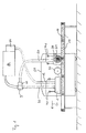
- the device according to the exemplary embodiment has a movable support frame 50 on which horizontally next to each other an injection hood 1, a pressure roller 20 and one Leveling device 30 with suction 60 is attached.
- the Pressure roller 20 is located between the injection hood 1 and the leveling device 30.
- the injection hood 1 is first opened a one-sided still open to be filled with blowing insulation Insulation chamber 13 of a wall, ceiling or roof element or the like 100 put on.
- the injection hood 1 points Insulation supply openings and air extraction openings so that while blowing insulation material into the insulation chamber 13 air can be extracted from this at the same time.
- the blowing hood 1 is attached to a lifting / lowering device 40 with which the Injection hood 1 while blowing insulation material onto the Chamber 13 pressed and then lifted from this again becomes.
- the injection hood 1 is via one or more insulation supply lines 12 connected to a blower 81, with the insulation pumped from an insulating material reservoir 80 to the injection hood 1 becomes.
- a Suction line 90 connected to a first suction pump device 9, those that are preferably extracted with the air suction Insulating material back into the insulation material reservoir 80.
- the insulation reservoir 80 and the blower 81 are located for example on a mobile blowing system.
- the pressure roller 20 is, based on the direction of movement (in Figure 1 represented by arrow 51) of the support frame 50 during operation of the device via the wall, ceiling or roof element or the like 100, the injection hood 1 downstream. With the pressure roller 20 one after lifting the Blow-in hood 1 projecting amount of insulation as much as possible pressed into the insulation chamber 13. The pressure roller 20 is moves and exercises for example via the insulation chamber 13 due to its own weight, pressure on the blown-in insulation out. But you can also hydraulic or the like with predetermined Pressure on the insulation material.
- the pressure roller 20 is, based on the direction of movement of the Device over the wall, ceiling or roof element or the like 100 in operation, the leveling device 30 downstream.
- the leveling device 30, for example a Rotating brush 31 has the previously blown and pressed insulation chamber 13 by one Brush off and vacuum off excess insulation material.
- the leveling facility 30 is preferably on a lifting / lowering device 41 attached to the level of Brush level is set.
- For suction of the brushed Insulation material is a suction line to the leveling device 30 60 connected to a suction pump device 61, which preferably put the excess insulation back into the Insulation reservoir 80 returns.
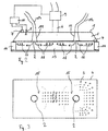
- the vacuum chamber 5 On the side facing away from the insulation chamber 13 during the blowing process Side of the cover plate 4 is a vacuum chamber 5, into which the air extraction holes 3 open.
- the vacuum chamber 5 has an air suction port 6, the is connected to an air extraction unit 9.
- a pressure measuring device 7 is arranged on the vacuum chamber 5, by means of a vacuum chamber 5 in operation arranged air inlet valve 8 and / or the suction power of the Air extraction unit 9 is controlled.
- One is preferred Electronic control unit 10 is provided, which is the air intake valve 8 and / or the suction power of the air extraction unit 9 by means of an electronic output signal of the pressure measuring device 7 controls.
- the cover plate 4 ( Figure 3) takes the diameter of the air exhaust holes 3 seen from each Insulation blowing opening 2 to the edge of the associated blowing area towards.
- the hole diameter of, for example, four Equidistant rows of holes are, for example, 5mm, 6mm, 7mm and 8mm.
- the cover plate 4 preferably has in each case on the Insulation injection openings 2 adjacent sub-areas 15 none Air extraction holes 3.
- each insulation opening 2 opens a conical, itself connecting pipe 11 widening towards the insulation blowing opening 2 for the connection of one insulation supply line 12.
- These connecting pipes 11 lead through the vacuum chamber 5 to the Insulation injection openings 12. Due to the conical shape frequent blockage of the insulation supply prevented.
- the blowing hood 1 For blowing in insulation material in insulation chambers 13 from The blowing hood 1 is on wall, ceiling or roof elements the one-sided still open to be filled with blowing insulation Insulation chamber 13 placed. Then the blow-in insulation through the insulation blowing openings 12 into the insulation chamber 13 blown in and at the same time air from the insulation chamber 13 suctioned off (indicated by the arrows 16 in Figure 2). The wall, ceiling or roof elements are then finished paneled and transported to the construction site.
Landscapes
- Engineering & Computer Science (AREA)
- Architecture (AREA)
- Civil Engineering (AREA)
- Structural Engineering (AREA)
- Building Environments (AREA)
- Working Measures On Existing Buildindgs (AREA)
Abstract
Description
- die Gebläsevorrichtung sowie das Dämm-Material muß zur die Baustelle transportiert werden - dies ist mit hohem Zeitund Personalaufwand verbunden;
- lange Schlauchwege von der Gebläsevorrichtung bis zu den Einblasstellen im Gebäude - infolgedessen besteht unter anderem erhöhte Gefahr für Schlauchverstopfungen;
- die Einblasstellen sind zum Teil nur mittels Leitern oder Gerüsten erreichbar, woraus sich ein erhöhter Arbeitsaufwand ergibt;
- keine Möglichkeit der direkten Überprüfung der Dichte und der Homogenität des Dämmstoffes in den Dämmstoffkammern nach dem Einblasen;
- erhöhter Arbeitsaufwand bei schwer zugänglichen oder verwinkelten Bereiche des Gebäudes;
- die Einblaslöcher in den Wandelementen müssen nach dem Einblasen luftdicht abgeschlossen werden, was einen zusätzlichen Arbeitsaufwand erfordert und eine potentielle Gefahr für Luftundichtigkeiten des Gebäudes darstellt;
- hohe Staub- und Lärmbbelastung.
Claims (15)
- Vorrichtung zum Einblasen von Einblasdämmstoff in Dämmstoffkammern von Wand-, Decken- oder Dachelementen oder dergleichen,
dadurch gekennzeichnet, daß
eine Einblashaube (1), eine Andrückeinrichtung (20) und eine Einebnungseinrichtung (30) vorgesehen sind. - Vorrichtung nach Anspruch 1,
dadurch gekennzeichnet, daß
die Einebnungseinrichtung (30) eine Dämmstoff-Absaugung (60) aufweist. - Vorrichtung nach Anspruch 1 oder 2,
dadurch gekennzeichnet, daß
die Einblashaube (1), die Andrückeinrichtung (20) und die Einebnungseinrichtung (30) an einem verfahrbaren Tragrahmen (50) angeordnet sind. - Vorrichtung nach Anspruch 3,
dadurch gekennzeichnet, daß
die Einblashaube (1), die Andrückeinrichtung (20) und die Einebnungseinrichtung (30) nebeneinander an dem verfahrbaren Tragrahmen (50) angeordnet sind (20), wobei die Andrückeinrichtung (20) zwischen der Einblashaube und der Einebnungseinrichtung (30) angeordnet ist. - Vorrichtung nach Anspruch 3,
dadurch gekennzeichnet, daß
die Einblashaube (1), die Andrückeinrichtung (20) und die Einebnungseinrichtung (30) an dem verfahrbaren Tragrahmen (50) relativ zueinander bewegbar, insbesondere an einer drehbaren Scheibe oder an einem drehbaren Rahmen, angeordnet sind (20). - Vorrichtung nach einem der Ansprüche 1 bis 5,
dadurch gekennzeichnet, daß
die Einblashaube (1) an eine mobile Dämmstoffzufuhreinrichtung (81), insbesondere mit zugeordnetem mobilen Dämmstoffreservoir (81), und an eine Luftabsaugeinrichtung (9) zum Absaugen von Luft aus einer Dämmstoffkammer (12) während des Einblasens von Dämmstoff in die Dämmstoffkammer (12) angeschlossen ist. - Einblashaube (1) zum Einblasen von Dämmstoff in einseitig zunächst noch unbeplankte Dämmstoffkammern von Wand-, Dekken- oder Dachelementen oder dergleichen, die eine mit mindestens einer Dämmstoffeinblasöffnung (2) und einer Mehrzahl von Luftabsauglöchern (3) versehene Abdeckplatte (4) aufweist, die zum Einblasen des Dämmstoffes auf die noch unbeplankte Seite der zu füllenden Dämmstoffkammer(n) aufgelegt wird.
- Einblashaube nach Anspruch 7, bei der die Luftabsauglöcher der Abdeckplatte (4) auf der beim Einblasvorgang von der Dämmstoffkammer abgewandten Seite in eine Unterdruckkammer (5) münden, die mindestens einen Luft-Absauganschluß (6) aufweist.
- Einblashaube nach Anspruch 8, bei der zur Einstellung eines möglichst konstanten Unterdruckes in der Unterdruckkammer (5) an dieser ein Druckmessgerät (7) angeordnet ist, vermittels dem im Betrieb ein an der Unterdruckkammer (5) angeordnetes Lufteinlaßventil (8) und/oder die Saugleistung einer Luftabsaugvorrichtung (9) gesteuert wird.
- Einblashaube nach Anspruch 9, bei der eine elektronische Steuereinheit (10) vorgesehen ist, die das Lufteinlaßventil (8) und/oder die Saugleistung einer Luftabsaugvorrichtung (9) vermittles eines Ausgangssignals des Druckmessgeräts (7) steuert.
- Einblashaube nach einem der Ansprüche 7 bis 10, bei der die Größe der Luftabsauglöcher (3) gesehen von jeder Dämmstoffeinblasöffnung (2) zum Rand des zugehörigen Einblasbereiches hin zunimmt.
- Einblashaube nach einem der Ansprüche 7 bis 11, bei der die Anzahl der Luftabsauglöcher (3) pro Flächeneinheit gesehen von der Dämmstoffeinblasöffnung (2) zum Rand des zugehörigen Einblasbereichs hin zunimmt.
- Einblashaube nach einem der Ansprüche 7 bis 12, bei der die Abdeckplatte (4) über eine an die Dämmstoffeinblasöffnung (2) angrenzende Teilfläche keine Luftabsauglöcher (3) aufweist.
- Einblashaube nach einem der Ansprüche 7 bis 13, bei der an jeder Dämmstoffeinblasöffnung (2) ein Anschlußrohr (11) für eine Dämmstoffzuleitung (12) vorgesehen ist, dessen Durchmesser zur Dämmstoffeinblasöffnung (2) hin zunimmt.
- Einblashaube nach Anspruch 14, bei der das Anschlußrohr (11) durch die Unterdruckkammer (5) verläuft.
Applications Claiming Priority (2)
| Application Number | Priority Date | Filing Date | Title |
|---|---|---|---|
| DE20106489U DE20106489U1 (de) | 2001-04-14 | 2001-04-14 | Vorrichtung zum Einblasen von Einblasdämmstoffen in Dämmstoffkammern von Wand-, Decken- oder Dachelementen |
| DE20106489U | 2001-04-14 |
Publications (3)
| Publication Number | Publication Date |
|---|---|
| EP1255001A2 true EP1255001A2 (de) | 2002-11-06 |
| EP1255001A3 EP1255001A3 (de) | 2003-03-26 |
| EP1255001B1 EP1255001B1 (de) | 2005-09-28 |
Family
ID=7955724
Family Applications (1)
| Application Number | Title | Priority Date | Filing Date |
|---|---|---|---|
| EP02008528A Expired - Lifetime EP1255001B1 (de) | 2001-04-14 | 2002-04-15 | Vorrichtung und Verfahren zum Einblasen von Einblasdämmstoff in Dämmstoffkammern von Wand-, Decken- oder Dachelementen |
Country Status (3)
| Country | Link |
|---|---|
| EP (1) | EP1255001B1 (de) |
| AT (1) | ATE305551T1 (de) |
| DE (2) | DE20106489U1 (de) |
Cited By (5)
| Publication number | Priority date | Publication date | Assignee | Title |
|---|---|---|---|---|
| EP3246490A1 (de) * | 2016-05-20 | 2017-11-22 | isofloc AG | Verfahren und vorrichtung zum einblasen von einblasdämmstoff in dämmstoffkammern von bauelementen |
| CN111636649A (zh) * | 2020-05-22 | 2020-09-08 | 新十建设集团有限公司 | 建筑施工用楼顶表面粗化装置 |
| CN112031340A (zh) * | 2020-09-27 | 2020-12-04 | 深圳千里马装饰集团有限公司 | 建筑贴瓷砖用水泥均匀性涂抹设备 |
| EP4033050A1 (de) * | 2021-01-20 | 2022-07-27 | Zellulosedämmstoffproduktion CPH Beteiligungs GmbH & Co KG | Vorrichtung zum einblasen von dämmstoff |
| EP4202152A1 (de) * | 2021-12-22 | 2023-06-28 | GUTEX Holzfaserplattenwerk H. Henselmann GmbH + Co KG | Vorrichtung zum einblasen von dämmstoff |
Families Citing this family (8)
| Publication number | Priority date | Publication date | Assignee | Title |
|---|---|---|---|---|
| EP2333199A1 (de) | 2009-12-03 | 2011-06-15 | isofloc AG | Vorrichtung und Verfahren zum Einblasen von Einblasdämmstoff in Dämmstoffkammern |
| EP2657431A1 (de) | 2012-04-23 | 2013-10-30 | isofloc AG | Einblasspitze, Einblasvorrichtung sowie Verfahren zum Einblasen von Einblasdämmstoffen in Dämmstoffkammern |
| FR2989291A1 (fr) * | 2012-09-20 | 2013-10-18 | Gaztransp Et Technigaz | Remplissage d'un caisson avec une matiere isolante fibreuse |
| AT520562B1 (de) * | 2017-12-01 | 2019-05-15 | Isocell Gmbh | Vorrichtung zum Einblasen von Dämmstoff |
| CN112252677A (zh) * | 2020-10-23 | 2021-01-22 | 浙江吉祥建设集团有限公司 | 一种高效建筑辅助粉刷墙壁设备 |
| CN112609929B (zh) * | 2020-12-15 | 2021-12-24 | 荣成市森源装饰工程有限公司 | 一种用于屋顶刮腻子的机器 |
| CN115030449B (zh) * | 2021-03-03 | 2023-10-03 | 广东博智林机器人有限公司 | 一种涂料装置及滚涂设备 |
| DE102021131257B4 (de) | 2021-11-29 | 2024-01-25 | GEKO Maschinenbau GmbH | Vorrichtung zum Einbringen von Dämmstoff in eine Dämmstoffkammer |
Family Cites Families (6)
| Publication number | Priority date | Publication date | Assignee | Title |
|---|---|---|---|---|
| US2989790A (en) * | 1957-06-10 | 1961-06-27 | Judd A Brown | Apparatus and method for applying and packing fibrous material |
| US4504525A (en) * | 1982-08-05 | 1985-03-12 | Chicago Bridge & Iron Company | Method of coating the walls of narrow vertical elongated spaces |
| US5355653A (en) * | 1993-03-29 | 1994-10-18 | Clarence Henri | Apparatus and method for installing loose fill or particulate insulation |
| PT832332E (pt) * | 1995-01-03 | 2002-02-28 | Aislo Oy | Produto de isolamento e processo para a sua producao |
| GB9708117D0 (en) * | 1996-11-07 | 1997-06-11 | Excel Ind Ltd | Methods and apparatus for introducing air-entrainable material into a chanel or recess |
| DE10007912A1 (de) * | 2000-02-21 | 2001-08-23 | Markus Gleixner | Verfahren zum Einblasen von Einbalsdämmstoff in Dämmstoffkammern von Wand-, Decken- oder Dachelementen und Einblashaube zur Durchführung des Verfahrens |
-
2001
- 2001-04-14 DE DE20106489U patent/DE20106489U1/de not_active Expired - Lifetime
-
2002
- 2002-04-15 DE DE50204360T patent/DE50204360D1/de not_active Expired - Lifetime
- 2002-04-15 AT AT02008528T patent/ATE305551T1/de not_active IP Right Cessation
- 2002-04-15 EP EP02008528A patent/EP1255001B1/de not_active Expired - Lifetime
Cited By (5)
| Publication number | Priority date | Publication date | Assignee | Title |
|---|---|---|---|---|
| EP3246490A1 (de) * | 2016-05-20 | 2017-11-22 | isofloc AG | Verfahren und vorrichtung zum einblasen von einblasdämmstoff in dämmstoffkammern von bauelementen |
| CN111636649A (zh) * | 2020-05-22 | 2020-09-08 | 新十建设集团有限公司 | 建筑施工用楼顶表面粗化装置 |
| CN112031340A (zh) * | 2020-09-27 | 2020-12-04 | 深圳千里马装饰集团有限公司 | 建筑贴瓷砖用水泥均匀性涂抹设备 |
| EP4033050A1 (de) * | 2021-01-20 | 2022-07-27 | Zellulosedämmstoffproduktion CPH Beteiligungs GmbH & Co KG | Vorrichtung zum einblasen von dämmstoff |
| EP4202152A1 (de) * | 2021-12-22 | 2023-06-28 | GUTEX Holzfaserplattenwerk H. Henselmann GmbH + Co KG | Vorrichtung zum einblasen von dämmstoff |
Also Published As
| Publication number | Publication date |
|---|---|
| DE20106489U1 (de) | 2001-09-06 |
| DE50204360D1 (de) | 2005-11-03 |
| ATE305551T1 (de) | 2005-10-15 |
| EP1255001A3 (de) | 2003-03-26 |
| EP1255001B1 (de) | 2005-09-28 |
Similar Documents
| Publication | Publication Date | Title |
|---|---|---|
| EP1255001B1 (de) | Vorrichtung und Verfahren zum Einblasen von Einblasdämmstoff in Dämmstoffkammern von Wand-, Decken- oder Dachelementen | |
| DE29911454U1 (de) | Vorrichtung zum Putzauftrag auf Gebäudewände | |
| DE2460033B2 (de) | Vorrichtung zum entwaessern von beton am druckring einer schildvortriebsmaschine | |
| DE3306044A1 (de) | Verfahren zum trocknen von materialien | |
| EP0077070A1 (de) | Verfahren und Vorrichtung zum Setzen höhennivellierter Sockelelemente eines Doppelbodens | |
| DE3306045A1 (de) | Verfahren zm trocknen von materialien unterhalb von estrichboeden | |
| DE2446768C3 (de) | Vorrichtung zum Einrütteln von Dübeln in Straßendecken aus Beton | |
| DE10007912A1 (de) | Verfahren zum Einblasen von Einbalsdämmstoff in Dämmstoffkammern von Wand-, Decken- oder Dachelementen und Einblashaube zur Durchführung des Verfahrens | |
| DE2520773C2 (de) | Verfahren zur Herstellung von Putzschichten tragenden, gegebenenfalls bewehrten, vorgefertigten Mauerwerktafeln sowie Vorrichtung zur Durchführung des Verfahrens | |
| DE19808812C2 (de) | Verfahren zur Herstellung einer festen Fahrbahn | |
| DE19711388C1 (de) | Vorrichtung zum Aufbringen von Trennmittel auf Schalungsteile | |
| DE3202336C2 (de) | ||
| DE69317192T2 (de) | Verfahren und Werkzeug zur Beschichtung einer Mauer | |
| DE3324306C2 (de) | Vorrichtung zum Verputzen, insbesondere an Gebäudeinnenwänden | |
| DE2922154C2 (de) | Gleitschalungsfertiger zum Auflegen einer Betonschicht auf einen Unterbau | |
| DE19813583A1 (de) | Verfahren und Vorrichtung zur Herstellung von Mauerwerk | |
| DE102021003409B4 (de) | Anordnung von Vorrichtungen und Verfahren zur Vereinfachung der Einbringung von Hausanschlussleitungen in Bauwerken | |
| DE60304415T2 (de) | Verfahren und Vorrichtung zum Errichten von Mauerwerk | |
| DE2618657A1 (de) | Moertelbandauflegevorrichtung zur herstellung von moertelbettungen an waenden | |
| WO2006128638A1 (de) | Vorrichtung zur unterdruckbehandlung von beton | |
| CH655045A5 (de) | Schalungsvorrichtung zur herstellung von quaderfoermigen, stirnseitig offenen fertiggaragen aus stahlbeton. | |
| DE4316568C1 (de) | Verfahren und Vorrichtung zur Herstellung von vorzugsweise mit Aussparungen versehenen rechteckigen Betonteilen | |
| DE4411373C2 (de) | Verfahren zum Erstellen einer offenen Baukonstruktion im Boden | |
| DE3437639C1 (de) | Abstandhalter für die Bewehrung einer Stahlbetonplatte | |
| DE19520692A1 (de) | Verfahren zum Herstellen einer Vertikalsperre gegen Wasser und Feuchtigkeit an der Außenfläche einer Gebäudegrundmauer sowie Vorrichtung zur Verwendung bei diesem Verfahren |
Legal Events
| Date | Code | Title | Description |
|---|---|---|---|
| PUAI | Public reference made under article 153(3) epc to a published international application that has entered the european phase |
Free format text: ORIGINAL CODE: 0009012 |
|
| AK | Designated contracting states |
Kind code of ref document: A2 Designated state(s): AT BE CH CY DE DK ES FI FR GB GR IE IT LI LU MC NL PT SE TR |
|
| AX | Request for extension of the european patent |
Free format text: AL;LT;LV;MK;RO;SI |
|
| PUAL | Search report despatched |
Free format text: ORIGINAL CODE: 0009013 |
|
| AK | Designated contracting states |
Kind code of ref document: A3 Designated state(s): AT BE CH CY DE DK ES FI FR GB GR IE IT LI LU MC NL PT SE TR |
|
| AX | Request for extension of the european patent |
Extension state: AL LT LV MK RO SI |
|
| 17P | Request for examination filed |
Effective date: 20030910 |
|
| AKX | Designation fees paid |
Designated state(s): AT BE CH CY DE DK ES FI FR GB GR IE IT LI LU MC NL PT SE TR |
|
| 17Q | First examination report despatched |
Effective date: 20031117 |
|
| GRAP | Despatch of communication of intention to grant a patent |
Free format text: ORIGINAL CODE: EPIDOSNIGR1 |
|
| RTI1 | Title (correction) |
Free format text: DEVICE AND METHOD FOR THE BLOWING IN OF INSULATING MATERIAL IN HOLLOWS OF WALL, CEILING OR ROOFING ELEMENTS |
|
| GRAS | Grant fee paid |
Free format text: ORIGINAL CODE: EPIDOSNIGR3 |
|
| GRAA | (expected) grant |
Free format text: ORIGINAL CODE: 0009210 |
|
| AK | Designated contracting states |
Kind code of ref document: B1 Designated state(s): AT BE CH CY DE DK ES FI FR GB GR IE IT LI LU MC NL PT SE TR |
|
| PG25 | Lapsed in a contracting state [announced via postgrant information from national office to epo] |
Ref country code: IT Free format text: LAPSE BECAUSE OF FAILURE TO SUBMIT A TRANSLATION OF THE DESCRIPTION OR TO PAY THE FEE WITHIN THE PRESCRIBED TIME-LIMIT;WARNING: LAPSES OF ITALIAN PATENTS WITH EFFECTIVE DATE BEFORE 2007 MAY HAVE OCCURRED AT ANY TIME BEFORE 2007. THE CORRECT EFFECTIVE DATE MAY BE DIFFERENT FROM THE ONE RECORDED. Effective date: 20050928 Ref country code: NL Free format text: LAPSE BECAUSE OF FAILURE TO SUBMIT A TRANSLATION OF THE DESCRIPTION OR TO PAY THE FEE WITHIN THE PRESCRIBED TIME-LIMIT Effective date: 20050928 Ref country code: GB Free format text: LAPSE BECAUSE OF FAILURE TO SUBMIT A TRANSLATION OF THE DESCRIPTION OR TO PAY THE FEE WITHIN THE PRESCRIBED TIME-LIMIT Effective date: 20050928 Ref country code: IE Free format text: LAPSE BECAUSE OF FAILURE TO SUBMIT A TRANSLATION OF THE DESCRIPTION OR TO PAY THE FEE WITHIN THE PRESCRIBED TIME-LIMIT Effective date: 20050928 Ref country code: FI Free format text: LAPSE BECAUSE OF FAILURE TO SUBMIT A TRANSLATION OF THE DESCRIPTION OR TO PAY THE FEE WITHIN THE PRESCRIBED TIME-LIMIT Effective date: 20050928 |
|
| REG | Reference to a national code |
Ref country code: GB Ref legal event code: FG4D Free format text: NOT ENGLISH |
|
| REG | Reference to a national code |
Ref country code: CH Ref legal event code: EP |
|
| REG | Reference to a national code |
Ref country code: IE Ref legal event code: FG4D Free format text: LANGUAGE OF EP DOCUMENT: GERMAN |
|
| REF | Corresponds to: |
Ref document number: 50204360 Country of ref document: DE Date of ref document: 20051103 Kind code of ref document: P |
|
| PG25 | Lapsed in a contracting state [announced via postgrant information from national office to epo] |
Ref country code: DK Free format text: LAPSE BECAUSE OF FAILURE TO SUBMIT A TRANSLATION OF THE DESCRIPTION OR TO PAY THE FEE WITHIN THE PRESCRIBED TIME-LIMIT Effective date: 20051228 Ref country code: SE Free format text: LAPSE BECAUSE OF FAILURE TO SUBMIT A TRANSLATION OF THE DESCRIPTION OR TO PAY THE FEE WITHIN THE PRESCRIBED TIME-LIMIT Effective date: 20051228 Ref country code: GR Free format text: LAPSE BECAUSE OF FAILURE TO SUBMIT A TRANSLATION OF THE DESCRIPTION OR TO PAY THE FEE WITHIN THE PRESCRIBED TIME-LIMIT Effective date: 20051228 |
|
| PG25 | Lapsed in a contracting state [announced via postgrant information from national office to epo] |
Ref country code: ES Free format text: LAPSE BECAUSE OF FAILURE TO SUBMIT A TRANSLATION OF THE DESCRIPTION OR TO PAY THE FEE WITHIN THE PRESCRIBED TIME-LIMIT Effective date: 20060108 |
|
| PG25 | Lapsed in a contracting state [announced via postgrant information from national office to epo] |
Ref country code: PT Free format text: LAPSE BECAUSE OF FAILURE TO SUBMIT A TRANSLATION OF THE DESCRIPTION OR TO PAY THE FEE WITHIN THE PRESCRIBED TIME-LIMIT Effective date: 20060228 |
|
| NLV1 | Nl: lapsed or annulled due to failure to fulfill the requirements of art. 29p and 29m of the patents act | ||
| GBV | Gb: ep patent (uk) treated as always having been void in accordance with gb section 77(7)/1977 [no translation filed] |
Effective date: 20050928 |
|
| PG25 | Lapsed in a contracting state [announced via postgrant information from national office to epo] |
Ref country code: LI Free format text: LAPSE BECAUSE OF NON-PAYMENT OF DUE FEES Effective date: 20060430 Ref country code: MC Free format text: LAPSE BECAUSE OF NON-PAYMENT OF DUE FEES Effective date: 20060430 Ref country code: BE Free format text: LAPSE BECAUSE OF NON-PAYMENT OF DUE FEES Effective date: 20060430 |
|
| REG | Reference to a national code |
Ref country code: IE Ref legal event code: FD4D |
|
| PLBE | No opposition filed within time limit |
Free format text: ORIGINAL CODE: 0009261 |
|
| STAA | Information on the status of an ep patent application or granted ep patent |
Free format text: STATUS: NO OPPOSITION FILED WITHIN TIME LIMIT |
|
| 26N | No opposition filed |
Effective date: 20060629 |
|
| EN | Fr: translation not filed | ||
| PG25 | Lapsed in a contracting state [announced via postgrant information from national office to epo] |
Ref country code: FR Free format text: LAPSE BECAUSE OF FAILURE TO SUBMIT A TRANSLATION OF THE DESCRIPTION OR TO PAY THE FEE WITHIN THE PRESCRIBED TIME-LIMIT Effective date: 20061124 |
|
| REG | Reference to a national code |
Ref country code: CH Ref legal event code: PL |
|
| REG | Reference to a national code |
Ref country code: CH Ref legal event code: NV Representative=s name: PATENTANWALTSKANZLEI NUECKEL Ref country code: CH Ref legal event code: AEN Free format text: DAS PATENT IST AUFGRUND DES WEITERBEHANDLUNGSANTRAGS VOM 12.01.2007 REAKTIVIERT WORDEN. |
|
| BERE | Be: lapsed |
Owner name: GLEIXNER, MARKUS Effective date: 20060430 |
|
| PG25 | Lapsed in a contracting state [announced via postgrant information from national office to epo] |
Ref country code: LU Free format text: LAPSE BECAUSE OF NON-PAYMENT OF DUE FEES Effective date: 20060415 Ref country code: TR Free format text: LAPSE BECAUSE OF FAILURE TO SUBMIT A TRANSLATION OF THE DESCRIPTION OR TO PAY THE FEE WITHIN THE PRESCRIBED TIME-LIMIT Effective date: 20050928 |
|
| PGFP | Annual fee paid to national office [announced via postgrant information from national office to epo] |
Ref country code: AT Payment date: 20080424 Year of fee payment: 7 |
|
| PG25 | Lapsed in a contracting state [announced via postgrant information from national office to epo] |
Ref country code: CY Free format text: LAPSE BECAUSE OF FAILURE TO SUBMIT A TRANSLATION OF THE DESCRIPTION OR TO PAY THE FEE WITHIN THE PRESCRIBED TIME-LIMIT Effective date: 20050928 Ref country code: FR Free format text: LAPSE BECAUSE OF FAILURE TO SUBMIT A TRANSLATION OF THE DESCRIPTION OR TO PAY THE FEE WITHIN THE PRESCRIBED TIME-LIMIT Effective date: 20050928 |
|
| PGFP | Annual fee paid to national office [announced via postgrant information from national office to epo] |
Ref country code: CH Payment date: 20081007 Year of fee payment: 7 |
|
| REG | Reference to a national code |
Ref country code: CH Ref legal event code: PCAR Free format text: PATENTANWALTSKANZLEI NUECKEL;WEINBERGLISTRASSE 4;6005 LUZERN (CH) |
|
| REG | Reference to a national code |
Ref country code: CH Ref legal event code: PL |
|
| PG25 | Lapsed in a contracting state [announced via postgrant information from national office to epo] |
Ref country code: CH Free format text: LAPSE BECAUSE OF NON-PAYMENT OF DUE FEES Effective date: 20090430 Ref country code: AT Free format text: LAPSE BECAUSE OF NON-PAYMENT OF DUE FEES Effective date: 20090415 Ref country code: LI Free format text: LAPSE BECAUSE OF NON-PAYMENT OF DUE FEES Effective date: 20090430 |
|
| PGFP | Annual fee paid to national office [announced via postgrant information from national office to epo] |
Ref country code: DE Payment date: 20101026 Year of fee payment: 9 |
|
| PG25 | Lapsed in a contracting state [announced via postgrant information from national office to epo] |
Ref country code: DE Free format text: LAPSE BECAUSE OF NON-PAYMENT OF DUE FEES Effective date: 20111101 |
|
| REG | Reference to a national code |
Ref country code: DE Ref legal event code: R119 Ref document number: 50204360 Country of ref document: DE Effective date: 20111101 |