EP1251467B1 - Machine remote monitoring system and management method - Google Patents
Machine remote monitoring system and management method Download PDFInfo
- Publication number
- EP1251467B1 EP1251467B1 EP02003109A EP02003109A EP1251467B1 EP 1251467 B1 EP1251467 B1 EP 1251467B1 EP 02003109 A EP02003109 A EP 02003109A EP 02003109 A EP02003109 A EP 02003109A EP 1251467 B1 EP1251467 B1 EP 1251467B1
- Authority
- EP
- European Patent Office
- Prior art keywords
- machine
- failure
- remote monitoring
- troubleshooting
- monitoring apparatus
- Prior art date
- Legal status (The legal status is an assumption and is not a legal conclusion. Google has not performed a legal analysis and makes no representation as to the accuracy of the status listed.)
- Expired - Lifetime
Links
- 238000012544 monitoring process Methods 0.000 title claims description 63
- 238000007726 management method Methods 0.000 title claims description 23
- 238000012423 maintenance Methods 0.000 claims description 60
- 230000006854 communication Effects 0.000 claims description 54
- 238000004891 communication Methods 0.000 claims description 54
- 238000013024 troubleshooting Methods 0.000 claims description 51
- 238000001514 detection method Methods 0.000 claims description 10
- 230000004044 response Effects 0.000 claims description 10
- 230000005540 biological transmission Effects 0.000 claims description 5
- 230000008439 repair process Effects 0.000 description 9
- 239000000047 product Substances 0.000 description 7
- 230000006870 function Effects 0.000 description 6
- 238000000034 method Methods 0.000 description 6
- 230000008859 change Effects 0.000 description 5
- 230000000737 periodic effect Effects 0.000 description 5
- 238000010586 diagram Methods 0.000 description 4
- 238000011161 development Methods 0.000 description 3
- 230000018109 developmental process Effects 0.000 description 3
- 238000003745 diagnosis Methods 0.000 description 3
- 238000012790 confirmation Methods 0.000 description 2
- 230000003111 delayed effect Effects 0.000 description 2
- 238000011156 evaluation Methods 0.000 description 2
- 230000002159 abnormal effect Effects 0.000 description 1
- 230000007175 bidirectional communication Effects 0.000 description 1
- 239000000498 cooling water Substances 0.000 description 1
- 230000007613 environmental effect Effects 0.000 description 1
- 230000006872 improvement Effects 0.000 description 1
- 230000003993 interaction Effects 0.000 description 1
- 238000011835 investigation Methods 0.000 description 1
- 210000004185 liver Anatomy 0.000 description 1
- 238000012545 processing Methods 0.000 description 1
- 239000013589 supplement Substances 0.000 description 1
- 230000033772 system development Effects 0.000 description 1
Images


Classifications
-
- G—PHYSICS
- G05—CONTROLLING; REGULATING
- G05B—CONTROL OR REGULATING SYSTEMS IN GENERAL; FUNCTIONAL ELEMENTS OF SUCH SYSTEMS; MONITORING OR TESTING ARRANGEMENTS FOR SUCH SYSTEMS OR ELEMENTS
- G05B23/00—Testing or monitoring of control systems or parts thereof
- G05B23/02—Electric testing or monitoring
- G05B23/0205—Electric testing or monitoring by means of a monitoring system capable of detecting and responding to faults
- G05B23/0259—Electric testing or monitoring by means of a monitoring system capable of detecting and responding to faults characterized by the response to fault detection
- G05B23/0275—Fault isolation and identification, e.g. classify fault; estimate cause or root of failure
-
- G—PHYSICS
- G05—CONTROLLING; REGULATING
- G05B—CONTROL OR REGULATING SYSTEMS IN GENERAL; FUNCTIONAL ELEMENTS OF SUCH SYSTEMS; MONITORING OR TESTING ARRANGEMENTS FOR SUCH SYSTEMS OR ELEMENTS
- G05B23/00—Testing or monitoring of control systems or parts thereof
- G05B23/02—Electric testing or monitoring
-
- G—PHYSICS
- G07—CHECKING-DEVICES
- G07C—TIME OR ATTENDANCE REGISTERS; REGISTERING OR INDICATING THE WORKING OF MACHINES; GENERATING RANDOM NUMBERS; VOTING OR LOTTERY APPARATUS; ARRANGEMENTS, SYSTEMS OR APPARATUS FOR CHECKING NOT PROVIDED FOR ELSEWHERE
- G07C5/00—Registering or indicating the working of vehicles
- G07C5/008—Registering or indicating the working of vehicles communicating information to a remotely located station
-
- F—MECHANICAL ENGINEERING; LIGHTING; HEATING; WEAPONS; BLASTING
- F02—COMBUSTION ENGINES; HOT-GAS OR COMBUSTION-PRODUCT ENGINE PLANTS
- F02D—CONTROLLING COMBUSTION ENGINES
- F02D2200/00—Input parameters for engine control
- F02D2200/02—Input parameters for engine control the parameters being related to the engine
- F02D2200/04—Engine intake system parameters
- F02D2200/0404—Throttle position
-
- F—MECHANICAL ENGINEERING; LIGHTING; HEATING; WEAPONS; BLASTING
- F02—COMBUSTION ENGINES; HOT-GAS OR COMBUSTION-PRODUCT ENGINE PLANTS
- F02D—CONTROLLING COMBUSTION ENGINES
- F02D2200/00—Input parameters for engine control
- F02D2200/02—Input parameters for engine control the parameters being related to the engine
- F02D2200/04—Engine intake system parameters
- F02D2200/0406—Intake manifold pressure
-
- F—MECHANICAL ENGINEERING; LIGHTING; HEATING; WEAPONS; BLASTING
- F02—COMBUSTION ENGINES; HOT-GAS OR COMBUSTION-PRODUCT ENGINE PLANTS
- F02D—CONTROLLING COMBUSTION ENGINES
- F02D2200/00—Input parameters for engine control
- F02D2200/02—Input parameters for engine control the parameters being related to the engine
- F02D2200/06—Fuel or fuel supply system parameters
- F02D2200/0602—Fuel pressure
- F02D2200/0604—Estimation of fuel pressure
-
- F—MECHANICAL ENGINEERING; LIGHTING; HEATING; WEAPONS; BLASTING
- F02—COMBUSTION ENGINES; HOT-GAS OR COMBUSTION-PRODUCT ENGINE PLANTS
- F02D—CONTROLLING COMBUSTION ENGINES
- F02D2200/00—Input parameters for engine control
- F02D2200/70—Input parameters for engine control said parameters being related to the vehicle exterior
- F02D2200/703—Atmospheric pressure
-
- G—PHYSICS
- G07—CHECKING-DEVICES
- G07C—TIME OR ATTENDANCE REGISTERS; REGISTERING OR INDICATING THE WORKING OF MACHINES; GENERATING RANDOM NUMBERS; VOTING OR LOTTERY APPARATUS; ARRANGEMENTS, SYSTEMS OR APPARATUS FOR CHECKING NOT PROVIDED FOR ELSEWHERE
- G07C5/00—Registering or indicating the working of vehicles
- G07C5/006—Indicating maintenance
-
- H—ELECTRICITY
- H04—ELECTRIC COMMUNICATION TECHNIQUE
- H04L—TRANSMISSION OF DIGITAL INFORMATION, e.g. TELEGRAPHIC COMMUNICATION
- H04L51/00—User-to-user messaging in packet-switching networks, transmitted according to store-and-forward or real-time protocols, e.g. e-mail
Definitions
- the present invention relates to a machine remote monitoring system and a management method, and in particular, to a machine remote monitoring system, which monitors operating conditions of a plurality of machines via communication, and to a management method for carrying out a management such as maintenance of machine based on the monitored result.
- the management of the above work machines is generally entrusted to a user such as an operator operating these machines, and further, the judgment of failure is made by the user.
- a failure it is general that the user informs sales shop of the failure so as to receive a repair service.
- a management apparatus for mobile work machines has been proposed in Japanese Patent Application Laid-Open No. 7-273714 .
- the operating condition data of the work machine is transmitted to a maintenance management section using a mobile radio communication device portable by an operator of the work machine, and then, the management section effectively makes an analysis relative to maintenance based on the transmitted data.
- a machine failure monitoring apparatus has been proposed in Japanese Patent Application Laid-Open No. 11-65645 .
- a failure signal and operating data at that time are automatically transmitted to the host computer via a network, and then, the data is stored as failure monitored history data. Further, maintenance timing is determined based on the history data, and emergency break is carried out.
- the former apparatus when the operator connects the mobile radio communication device to a connector of data exchanger having modem, a data extracted from storage section is transmitted to the maintenance management section. Therefore, the operator's judgment is delay, and when no connection is made, the data is not transmitted, for this reason, there is the case where a failure is not found, or the finding-out is delayed.
- the above apparatus described in the Publication has been proposed for the purpose of making easy maintenance of machine doing work within a limited area. For this reason, the above apparatus has not been proposed considering machines movable in a wide area, therefore, improvement is still required.
- the management station side can manage the judgment of failure occurrence and maintenance timing with respect to a plurality of work machines.
- the actual repair work greatly depends upon the service engineer' s skill, for this reason, the user does not feel secure about his skill in view of quickness, and can not obtain satisfaction relative to the repair condition. Further, a problem arises such that it is difficult to secure communication security.
- US patent 6 181 994 B1 discloses a radio connected diagnostic system for a vehicle where a vehicle, being evaluated, connects to a network and downloads results in the evaluation to a diagnostic centre. If the evaluation does not require analysis according to the diagnostic centre, any problem is corrected in the vehicle. If the diagnostic centre is of the opinion that advanced diagnostics are required, the advanced diagnostics are loaded into the vehicle or serer.
- US patent 5 442 553 A discloses a transceiver and additional memory being connected to a microprocessor in a vehicle so that all, or selected portions, or operating data is restored in the memory and periodically transmitted to a remote station. The data is diagnosed at the remote station and, for minor repairs, a fix is transmitted back to the vehicle. The information for a large population of vehicles is used by the manufacturer to determine if a problem is generic to a specific model and to generate repairs and/or model changes.
- an object of the present invention is to provide a machine remote monitoring system and a management method, which can give accurate failure diagnosis and high reliability and safety with respect to repair to a user.
- the present invention provides a machine remote monitoring system for a machine comprising a call station connected with a machine via a communication unit and a remote monitoring apparatus, wherein said remote monitoring apparatus comprises: means for determining identification information of a call station in response to an incoming call from the call station; communication means for starting communication with the call station when the determining means makes a decision such that an incoming call comes from a previously registered call station and means for confirming an operating condition of the machine connected with the call station based on the machine condition data provided by sensors on the machine and transmitted at every predetermined time from the call station in the communication wherein said machine comprises means adapted to provide condition data indicative of failure occurrence detected in the machine side to the communication unit for transmission by the call station wherein said remote monitoring apparatus further comprises troubleshooting means, which starts up a predetermined program when indication of failure detected in the machine side is received, or when it is confirmed by the means for confirming an operating condition of the machine that the failure in the machine occurs based on the condition data,
- the present invention provides a machine management method comprising the steps of making an access to a remote monitoring apparatus from a call station connected to a communication unit, the communication unit being connected to a managed machine so as to transmit a condition data of the managed machine derived by sensors on the managed machine for at every predetermined time and whenever a failure is detected by an engine control unit on the managed machine or at one of these occasions; carrying out troubleshooting which starts up a predetermined program so as to detect the cause of failure when failure is detected by an engine control unit or when the remote monitoring apparatus confirms an occurrence of failure based on the condition data; and giving a message of the occurrence of failure and a cause of failure decided by troubleshooting step to a predetermined destination, wherein an access to the remote monitoring apparatus from the call station with the communication unit is made with identification information previously allocated to the managed machine, and the remote monitoring apparatus is started up in response to the access.
- condition data representing the operating condition of machine is supplied to the managing side, that is, the remote monitoring apparatus by making an access from a managed machine side.
- the remote monitoring apparatus makes a decision whether or not a failure occurs based on the condition data, and carries out troubleshooting for the failure. Therefore, it is possible to determine the failure based on the condition data before a failure is detected in the machine side, as well as when the failure is detected in the machine side.
- the troubleshooting program is downloaded from the database storing the latest information, therefore, suitable troubleshooting is possible.
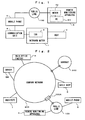
- Fig. 1 is a block diagram showing a configuration of outboard motor monitoring system according to one embodiment of the present invention.
- an outboard motor (engine) 1 is mounted in a boat 2, and further, includes a controller or an engine control unit (ECU) 3.
- the ECU 3 is connected to a communication unit 4 via a dedicated communication interface so that the ECU 3 and the communication unit 4 can mutually make data communication.
- the communication unit 4 is connected to a mobile phone 5, and the mobile phone 5 makes communication with the outside according to the instructions from the communication unit 4.
- the ECU 3 transmits detection data (described later) detected by various sensors included in the outboard motor 1 to the communication unit 4.
- the communication unit 4 transmits the detection data as condition data of the outboard motor 1 to a public line 100 via the mobile phone 5.
- a remote monitoring apparatus 6 has a personal computer 61 and a modem 62 connected to the public line 100.
- the personal computer 61 has a function of expressing the condition data of outboard motor 1 received from the mobile phone 5 via the public line 100 by chart and graph.
- the communication unit 4 makes a call to the remote monitoring apparatus 6 at a predetermined time or for each predetermined time.
- the remote monitoring apparatus 6 makes a response to only call from the outboard motor 1 side, and then, can make communication with the communication unit 4.
- the system is constructed in a manner that communication is not made even if the remote monitoring apparatus 6 makes an access to the outboard motor 1 side.
- the access from the outboard motor 1 side is not limited to the above timing, and may be made when the outboard motor 1 starts to operate and when the ECU 3 detects a failure of the outboard motor 1.
- the remote monitoring apparatus 6 is located in the marina.
- the data from plural outboard motors 1 is received and managed by one personal computer 61.
- Fig. 2 is a view showing a configuration of wide area network system including the remote monitoring apparatus 6.
- a leased line network 200 administrated by a maker company of the outboard motor 1 is connected with each computer of the maker main office and factory H, institute I and sails shops S and a database server (hereinafter, referred to as "server") DB.
- the remote monitoring apparatus 6 of the marina and the mobile phone 5 of the outboard motor 1 are connected to the company network 200 via the public line 100.
- the company network 200 and the public line 100 are connected via a gateway unit 200A. Further, the company network 200 is connected to Internet 300.
- the remote monitoring apparatus 6 may be directly arranged on the company network 200 without connecting the public line 100.
- Fig. 3 is a functional block diagram showing principal parts of the remote monitoring apparatus 6.
- the remote monitoring apparatus 6 is always operated, however, the remote monitoring apparatus 6 is not necessarily so operated.
- the remote monitoring apparatus 6 is made into a suspended state, and when the modem 62 detects a signal from the public line 100, the personal computer 61 may fully start up.
- a communication section 7 has a determining function (determining means 71).
- the determining means 71 collates peculiar identification information ID or a number allocated to product or the outboard motor 1 inputted from the communication unit 4 of the outboard motor 1 side, with previously registered data in response to incoming call. More specifically, the determining means 71 makes a decision whether the incoming call is unfair reception, that is, it is an incoming call from stations other than previously registered station. Then, when it is confirmed that the incoming call is fair reception, the communication means 72 starts bi-directional communication with the outboard motor 1. As described above, the communication is started only when the access from the outboard motor 1 side is made, and thereby, it is possible to prevent communication from being made when unfair access is made to the communication unit 4.
- a failure determining section 8 makes a decision whether or not a failure occurs in the outboard motor 1 side, that is, determines an operating condition of the outboard motor 1 based on the condition data from the outboard motor 1.
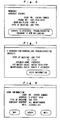
- Fig. 4 is a view showing condition data.
- the condition data includes sensor detection data such as engine temperature, failure information such as electric short and open of sensor signal indicative of the condition that a failure actually occurs, and maintenance information such as the total operating time used for determining maintenance timing.
- the above condition data is periodically transmitted to the remote monitoring apparatus 6 from the communication unit 4 at predetermined frequency such as one time for five minutes. Subsequently, the following is a description based on the assumption of the condition that a cooling water passage stop up, as a result, the engine is likely to overheat.
- the failure determining section 8 shown in Fig. 3 monitors a change of engine temperature periodically transmitted, that is, a rise rate of temperature, and has a function of detecting overheat based on the rise rate.
- a warning section 9 outputs a warning signal indicative of the occurrence of failure when inputting a signal of detecting overheat or sign of overheat from the failure determining section 8.
- the warning signal is supplied to a display section 10, and then, an alarm showing the overheat is displayed on a screen of the display section 10.
- the warning signal is inputted to a mail transmitting section 11 used as informing means, and then, the mail transmitting section 11 may give overheat detection information to a previously registered address via E-mail. In this case, a plurality of addresses may be registered. As described above, the occurrence of failure is transmitted via E-mail, and thereby, a maintenance staff of marina has no need of watching the remote monitoring apparatus 6, and therefore, can continue failure monitoring while doing other maintenance work at a remote place.
- the content of warning displayed on the display section 10 and the maintenance staff's mobile phone includes data for specifying the user, ID of the communication unit 4, failure contents, maintenance history (e.g., oil change history relative to overheat) and the like.
- the maintenance staff can determine the failure content based on the displayed content. Therefore, by the judgment of the maintenance staff, it is possible to give a message such that there is a fear of overheats to the boat 2 equipped with the outboard motor 1 by wireless and mobile phone.
- the boat 2 receives the message, and can confirm the failure, therefore, the boat 2 can take suitable measures of reducing a speed in order to relieve the overheat, and coming back to the marina.
- the ECU 3 of the outboard motor 1 can detect the overheat from an output from an overheat sensor provided in the outboard motor 1. In this case, it is possible to carry out a control for automatically reducing an engine speed of the outboard motor 1.
- the failure determining section 8 of the remote monitoring apparatus 6 can expect the occurrence of overheat judging from a degree of the rise of engine temperature, therefore, it is possible to prevent the occurrence of overheat.
- the personal computer 61 may have a function of automatically determining a degree of emergency for taking measures to the failure from the maintenance history and the rise rate of engine temperature, and displaying it on the display section 10.
- a troubleshoot section 12 has a program for displaying the cause corresponding to the failure, and detects the cause of failure corresponding to the failure content included in the warning signal so as to display the failure content and the cause of failure on the display section 10. Therefore, the maintenance staff of marina can give suitable measures for repairing the failure to the boat based on the displayed cause of failure, and can go out for maintenance by himself.
- a program stored in the troubleshooting section 12 may be data of storage medium previously provided from a maker for each product, and may be downloaded from the server DB of the maker. The data is downloaded from the server DB, and thereby, it is possible to carry out troubleshooting with higher accuracy based on the latest updated data of the maker.
- the condition data has been transmitted from the communication unit 4 at the frequency of one time for five minutes.
- the transmission frequency may be determined by a predetermined monitoring level.
- the condition data is periodically transmitted to the remote monitoring apparatus 6, and thereby, it is possible to estimate overheat before a failure such as overheat occurs.
- the condition data may be transmitted periodically when the operation starts, as described above.
- the data indicative of the failure condition can be immediately transmitted to the remote monitoring apparatus 6 when a failure is detected, in addition to the periodic transmission at the above frequency.
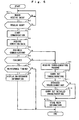
- Fig. 5 is a flowchart showing a monitoring operation including failure detection.
- step S1 a decision is made whether or not the modem 62 receives the data. If the reception is detected, the control sequence proceeds to step S2, it is confirmed whether or not the reception is access from regular users based on the identification information (ID). If it is access from regular users, in step S3, an acknowledge signal is transmitted to the communication unit 4 so that communication is started. In step S4, the condition data is acquired. In step S5, a decision is made whether or not the reception is periodic communication for each predetermined time.
- ID identification information
- step S6 a decision is made whether or not there is a failure based on the condition data. If there is no failure, the control sequence proceeds to step S7, and then, a decision is made whether or not maintenance timing, for example, oil change timing comes based on oil change history. According to the above judgment result, in step S8, maintenance information, for example, a message of suggesting "oil change" is displayed on the display section 10.
- step S5 if the reception is not periodic communication in step S5 (NO), a decision is made such that the ECU 3 of the outboard motor 1 side detects a failure, and the result is transmitted, and then, in steps after step S9, troubleshooting is carried out.
- step S6 the control sequence proceeds to steps S9.
- a program for troubleshooting is downloaded from the server DB, and then, troubleshooting is carried out.
- step S9 a demand of troubleshooting program is made to the server DB.
- the latest program is downloaded from the server DB, and thereafter, in steps S10, troubleshooting is carried out according to the downloaded program, and then, the result is displayed on the display section 10.
- the maintenance staff watches the displayed troubleshooting result, and then, can take suitable measures.
- the server DB is provided with the latest troubleshooting method from the institute I, therefore, more suitable troubleshooting is possible.
- step S11 a decision is made whether or not detailed troubleshooting is carried out.
- the instruction for the judgment is made by the maintenance staff.
- step S12 detailed troubleshooting is carried out.
- the troubleshooting result is stored in the server DB as user information in step S13.
- Fig. 6 shows a display screen of the display section 10 when the occurrence of failure is detected
- Fig. 7 shows the troubleshooting result
- Fig. 7 shows a display screen of the case where the overheat sensor of the outboard motor 1 detects overheat, and transmits a failure signal as condition data.
- the boat 2 includes a self-position detector (GPS) for giving current position information to the remote monitoring apparatus 6, the current position can be displayed on the display section 10. Further, the position of the boat 2 may be displayed on a map based on map information previously stored in the personal computer 61 and the position information.
- GPS self-position detector
- trouble information that is, information that a failure occurs or is likely to occur is given to the boat 2 by the mobile phone and mail.
- Necessary parts are determined when the cause of failure is decided, therefore, the necessary parts can be ordered via the network.
- a parts center is connected to the company network 200, and an access is made to the parts center so as to confirm stock and order it. The confirmation result of the stock is displayed together with part name as shown in Fig. 7 .
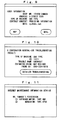
- Fig. 8 shows a parts order screen having a contract content of all maintenance.
- the order of the identified part is previously approved by the user, therefore, an "order" button on the screen is clicked, and thereby, the part is ordered.
- a "mail” button is clicked, and thereby, trouble information corresponding to the cause of failure is given to the user.
- a "map” button is clicked, and thereby, it is possible to display a map showing outside repair shop for maintenance.
- Fig. 9 is a view showing a display screen of the display section 10 in the case where the contract content with the user is "contract of providing information”.
- a "mail" button on the screen is clicked, and thereby, trouble information and maintenance cost are transmitted to predetermined user's mail address.
- information providing to the user is not limited to the mail, and may be performed by communication means such as telephone, facsimile, etc.
- Fig. 10 is a view showing a display screen of the display section 10 in the case where the cause of failure is not decided by only condition data from the outboard motor 1 side.
- the screen is provided with a "detailed troubleshooting" switch. The maintenance staff clicks the switch, and thereby, a demand of program for detailed troubleshooting is made with respect to the server DB.
- the troubleshooting result is stored in the server DB as user information correspondingly to user name.
- the user information stored in the database DB is used in the head office and factory H, the institute I, etc.
- the institute I acquires the user information from the server DB, and confirms "machine used information, environmental requirement (durable temperature), failure occurring place” or the like.
- the head office and factory H confirms "condition for each district, claim information” or the like, and can use the information for development and sale.
- the user information stored in the server DB is not only used for development and sale, but also used as useful maintenance information to the user.
- the company network 200 including the server DB is connected to the Internet 300. Therefore, the user designates a server URL, and then, inputs previously registered user name and password, and thereby, can make an access to the server DB on the company network 200 via the Internet 300.
- the server DB has a function of making a response to the access from the user, and processing the user information into a format such that the user is easy to see. Further, in response to the access from the user, it is possible to provide maintenance information about the outboard motor in which the user possesses, and to provide service for introducing optional parts based on new product information stored in the server DB.
- Fig. 11 is a view showing information displayed on user' s personal computer in response to the access from the user. The information as described above is displayed, and then, when the user clicks a check box positioned ahead the product name, detailed information for the product is displayed.
- Fig. 12 is a view showing a detailed information display screen for product. As shown in fig. 12 , a list of parts requiring maintenance or parts having maintenance timing coming soon is displayed. When the user checks an "order" box of the corresponding parts, and clicks an "OK” button, the screen is transferred to an order screen.
- Fig. 13 is a view showing an order screen outputted to the user's personal computer. As shown in Fig. 13 , previously registered destination and payment card number are displayed on the order screen. Based on information displayed on the order screen, when the user clicks an "OK" button for confirmation, the order of parts requiring maintenance is completed.
- Fig. 14 is a view showing an Internet auction display screen. The user inputs a desired selling price and clicks a "registration" button on the screen shown in Fig. 14 , and thereby, the registration for Internet auction is completed.
- the condition data of the outboard motor 1 is given periodically and automatically to the remote monitoring apparatus 6 of marina when the operation starts, when a failure occurs and regardless of the occurrence of failure. Then, the remote monitoring apparatus 6 confirms the condition of the outboard motor 1 based on the condition data, and carries out troubleshooting when a failure is detected. Further, in the case where the cause of failure is not decided by only condition data automatically transmitted from the outboard motor 1, the program for detailed troubleshooting is acquired from the server DB of maker, and then, according to the acquired program, the maintenance staff supplements new condition data so as to carry out an investigation.
- the troubleshooting result is collectively managed as user information by the server DB, therefore, sales and institute sections accessible to the server DB can carry out effective sale and development based on the user information. Further, the user inspects the user information via Internet, and then, can make use of the order of parts and Internet auction.
- This embodiment has described the monitoring apparatus of the outboard motor 1 and the management method.
- the present invention may be applicable to other machines, for example, engine generators. More specifically, engine condition data is transmitted via mobile phones while a sales shop is provided with the remote monitoring apparatus, and then, the sale shop monitors and manages the engine generator.
- the mobile phone has been used as communication means from the outboard motor 1.
- the present invention is not limited to the above communication means.
- the mobile phone can not make communication on the marine several tens of kilometers away from the coast, for this reason, in such a case, wireless communication means such as ship station radio is used.
- the maintenance side providing the remote monitoring apparatus can monitor user' s machine condition based on the condition data. Based on the monitored result, suitable judgment to failure and information on maintenance are given to the user side, therefore, it is possible to give reliability and safety to the user using the machine.
- condition data is monitored, therefore, it is possible to find a failure before the user takes notice of it.
- condition data is monitored, therefore, it is possible to carry out accurate failure diagnosis.
- the maintenance side already grasps the machine condition, and finishes troubleshooting for the failure. Therefore, the maintenance staff can immediately prepare maintenance parts, and can leave for the user to repair, as a result, quick and accurate maintenance is possible.
- the above troubleshooting is carried out according to the latest program acquired from the server, therefore, suitable failure diagnosis can be performed.
- condition data is transmitted to the maintenance side by only access from the machine side, therefore, high security can be secured.
- the user information including failure data is stored in the server, therefore, the user makes an access to the server, and can use the data as information for maintenance and operation.
Landscapes
- Physics & Mathematics (AREA)
- General Physics & Mathematics (AREA)
- Engineering & Computer Science (AREA)
- Automation & Control Theory (AREA)
- Management, Administration, Business Operations System, And Electronic Commerce (AREA)
- Telephonic Communication Services (AREA)
- Testing And Monitoring For Control Systems (AREA)
- Testing Of Devices, Machine Parts, Or Other Structures Thereof (AREA)
- Alarm Systems (AREA)
- Selective Calling Equipment (AREA)
Applications Claiming Priority (2)
| Application Number | Priority Date | Filing Date | Title |
|---|---|---|---|
| JP2001043668 | 2001-02-20 | ||
| JP2001043668A JP2002244724A (ja) | 2001-02-20 | 2001-02-20 | 機械の遠隔監視装置および管理方法 |
Publications (3)
| Publication Number | Publication Date |
|---|---|
| EP1251467A2 EP1251467A2 (en) | 2002-10-23 |
| EP1251467A3 EP1251467A3 (en) | 2005-04-20 |
| EP1251467B1 true EP1251467B1 (en) | 2010-08-11 |
Family
ID=18905794
Family Applications (1)
| Application Number | Title | Priority Date | Filing Date |
|---|---|---|---|
| EP02003109A Expired - Lifetime EP1251467B1 (en) | 2001-02-20 | 2002-02-13 | Machine remote monitoring system and management method |
Country Status (8)
| Country | Link |
|---|---|
| US (1) | US6836539B2 (enExample) |
| EP (1) | EP1251467B1 (enExample) |
| JP (1) | JP2002244724A (enExample) |
| KR (1) | KR20020068280A (enExample) |
| CN (1) | CN1372174A (enExample) |
| CA (1) | CA2369768C (enExample) |
| DE (1) | DE60237257D1 (enExample) |
| TW (1) | TW559690B (enExample) |
Families Citing this family (64)
| Publication number | Priority date | Publication date | Assignee | Title |
|---|---|---|---|---|
| US6978307B2 (en) * | 2001-07-19 | 2005-12-20 | Hewlett-Packard Development Company, L.P. | Apparatus and method for providing customer service |
| JP2003140737A (ja) * | 2001-10-30 | 2003-05-16 | Fujitsu Ten Ltd | サポートシステム |
| US6688561B2 (en) * | 2001-12-27 | 2004-02-10 | General Electric Company | Remote monitoring of grade crossing warning equipment |
| US20040021563A1 (en) * | 2002-07-31 | 2004-02-05 | Deere & Company | Method for remote monitoring equipment for an agricultural machine |
| DE10242919A1 (de) * | 2002-09-16 | 2004-03-25 | Siemens Ag | System zur virtuellen Prozessanbindung über Remote Desktop Protocol (RDP) |
| AU2003246302B2 (en) * | 2002-09-19 | 2008-07-10 | Honda Giken Kogyo Kabushiki Kaisha | Outboard motor |
| KR20040035534A (ko) * | 2002-10-22 | 2004-04-29 | 주식회사 커미조아 | 산업용 계측 제어기기의 비정상 상태 제어 방법 |
| US7299055B1 (en) * | 2002-10-25 | 2007-11-20 | Sprint Communications Company L.P. | Geographic representation of end user fixed wireless communication device |
| US7415243B2 (en) | 2003-03-27 | 2008-08-19 | Honda Giken Kogyo Kabushiki Kaisha | System, method and computer program product for receiving data from a satellite radio network |
| DE10345883A1 (de) * | 2003-09-30 | 2005-05-12 | Siemens Ag | Fertigungsvorrichtung mit automatischer Fernüberwachung und entsprechendes Überwachungsverfahren |
| US8041779B2 (en) | 2003-12-15 | 2011-10-18 | Honda Motor Co., Ltd. | Method and system for facilitating the exchange of information between a vehicle and a remote location |
| US7818380B2 (en) | 2003-12-15 | 2010-10-19 | Honda Motor Co., Ltd. | Method and system for broadcasting safety messages to a vehicle |
| WO2005099379A2 (en) | 2004-04-06 | 2005-10-27 | Honda Motor Co., Ltd. | Method and system for controlling the exchange of vehicle related messages |
| JP4349185B2 (ja) * | 2004-04-14 | 2009-10-21 | 株式会社日立製作所 | 車両監視装置 |
| US7518530B2 (en) | 2004-07-19 | 2009-04-14 | Honda Motor Co., Ltd. | Method and system for broadcasting audio and visual display messages to a vehicle |
| US7643788B2 (en) | 2004-09-22 | 2010-01-05 | Honda Motor Co., Ltd. | Method and system for broadcasting data messages to a vehicle |
| US7562049B2 (en) | 2005-03-29 | 2009-07-14 | Honda Motor Co., Ltd. | Payment system and method for data broadcasted from a remote location to vehicles |
| JP4471292B2 (ja) * | 2005-06-23 | 2010-06-02 | 本田技研工業株式会社 | 汎用エンジン完成検査方法 |
| US7949330B2 (en) | 2005-08-25 | 2011-05-24 | Honda Motor Co., Ltd. | System and method for providing weather warnings and alerts |
| US7493525B2 (en) | 2005-09-21 | 2009-02-17 | Cisco Technology, Inc. | Method and system for managing failure information |
| DE102006009098A1 (de) * | 2006-02-28 | 2007-08-30 | Daimlerchrysler Ag | Kraftfahrzeugdiagnose und Fahrzeugannahme |
| US7739007B2 (en) * | 2006-03-29 | 2010-06-15 | Snap-On Incorporated | Vehicle diagnostic method and system with intelligent data collection |
| KR100751528B1 (ko) * | 2006-05-12 | 2007-08-23 | 한국기계연구원 | 회전 기계 운전 상태 모바일 모니터링 시스템 |
| US8024149B2 (en) * | 2006-08-03 | 2011-09-20 | Titanium Metals Corporation | Overheat detection system |
| US7496475B2 (en) * | 2006-11-30 | 2009-02-24 | Solar Turbines Incorporated | Maintenance management of a machine |
| DE102007017772A1 (de) * | 2007-04-16 | 2008-10-23 | Maha Maschinenbau Haldenwang Gmbh & Co. Kg | Vorrichtung zum Anheben und/oder Überprüfen von Fahrzeugen und Verfahren zum Betrieb derselben |
| US7668653B2 (en) | 2007-05-31 | 2010-02-23 | Honda Motor Co., Ltd. | System and method for selectively filtering and providing event program information |
| GB2451118A (en) * | 2007-07-19 | 2009-01-21 | Dek Int Gmbh | Fault messaging system for machines using mobile communications |
| US8099308B2 (en) | 2007-10-02 | 2012-01-17 | Honda Motor Co., Ltd. | Method and system for vehicle service appointments based on diagnostic trouble codes |
| US8135804B2 (en) | 2009-07-07 | 2012-03-13 | Honda Motor Co., Ltd. | Method for scheduling and rescheduling vehicle service appointments |
| KR101143947B1 (ko) * | 2010-03-31 | 2012-05-15 | 대양전기공업 주식회사 | 브이에스에이티를 이용한 선박장비의 원격지원서비스시스템 |
| JP5925462B2 (ja) * | 2011-10-12 | 2016-05-25 | ヤンマー株式会社 | 走行作業機械又は船舶の遠隔監視端末装置 |
| JP5781426B2 (ja) * | 2011-12-02 | 2015-09-24 | ヤンマー株式会社 | 走行作業機械又は船舶の遠隔監視端末装置 |
| GB2501291A (en) * | 2012-04-19 | 2013-10-23 | Project Vanguard Ltd | Diagnostic system with predicted problem cause feedback |
| US8798847B2 (en) | 2012-05-16 | 2014-08-05 | The Morey Corporation | Method and system for remote diagnostics of vessels and watercrafts |
| CN103197666A (zh) * | 2013-03-26 | 2013-07-10 | 重庆邮电大学 | 一种通用型手持汽车故障诊断仪 |
| JP6141075B2 (ja) * | 2013-04-04 | 2017-06-07 | 三菱電機株式会社 | 監視制御システム、監視制御装置および監視制御方法 |
| US11055450B2 (en) * | 2013-06-10 | 2021-07-06 | Abb Power Grids Switzerland Ag | Industrial asset health model update |
| US10534361B2 (en) * | 2013-06-10 | 2020-01-14 | Abb Schweiz Ag | Industrial asset health model update |
| JP6209024B2 (ja) | 2013-08-28 | 2017-10-04 | ヤンマー株式会社 | 遠隔サーバ |
| US9720418B2 (en) | 2014-05-27 | 2017-08-01 | Here Global B.V. | Autonomous vehicle monitoring and control |
| JP6648962B2 (ja) * | 2014-10-07 | 2020-02-19 | ヤンマー株式会社 | 遠隔サーバ |
| CN104765316A (zh) * | 2015-03-24 | 2015-07-08 | 湖州炎弘电子有限公司 | 一种利用智能终端作为工业设备控制的人机界面的技术 |
| JP6472339B2 (ja) * | 2015-06-16 | 2019-02-20 | 株式会社日立製作所 | 効率低下要因分析装置及びプログラム |
| US10080132B2 (en) | 2016-03-28 | 2018-09-18 | Bank Of America Corporation | System for adaptation of multiple digital signatures in a distributed network |
| US10039113B2 (en) | 2016-03-28 | 2018-07-31 | Bank Of America Corporation | Intelligent resource procurement system based on physical proximity to related resources |
| US9743272B1 (en) * | 2016-03-28 | 2017-08-22 | Bank Of America Corporation | Security implementation for resource distribution |
| US10135817B2 (en) | 2016-03-28 | 2018-11-20 | Bank Of America Corporation | Enhancing authentication and source of proof through a dynamically updatable biometrics database |
| US20170278083A1 (en) * | 2016-03-28 | 2017-09-28 | Bank Of America Corporation | Security implementation for user resource distribution with peripheral device |
| US20170278098A1 (en) * | 2016-03-28 | 2017-09-28 | Bank Of America Corporation | Security implementation for user resource distribution |
| US10038607B2 (en) | 2016-06-17 | 2018-07-31 | Bank Of America Corporation | System for aggregated machine-initiated resource distribution |
| US10796253B2 (en) | 2016-06-17 | 2020-10-06 | Bank Of America Corporation | System for resource use allocation and distribution |
| US10103936B2 (en) | 2016-06-21 | 2018-10-16 | Bank Of America Corporation | Computerized resource reallocation system for transferring resource blocks based on custodian event |
| US10334462B2 (en) | 2016-06-23 | 2019-06-25 | Bank Of America Corporation | Predictive analytics for resource development based on information communicated from inter-related communication devices |
| US10439913B2 (en) | 2016-07-01 | 2019-10-08 | Bank Of America Corporation | Dynamic replacement and upgrade of existing resources based on resource utilization |
| US10127400B2 (en) | 2016-09-26 | 2018-11-13 | Bank Of America Corporation | Control device for aggregation and distribution of machine-initiated resource distribution |
| EP3579155B1 (en) * | 2017-01-31 | 2021-11-17 | Honda Motor Co., Ltd. | Unmanned work system, management server, and unmanned work machine |
| JP6908405B2 (ja) * | 2017-03-29 | 2021-07-28 | 本田技研工業株式会社 | 小型船舶の故障予測システム |
| CN110572526A (zh) * | 2019-08-16 | 2019-12-13 | 安徽信息工程学院 | 线路保护装置远程监控系统 |
| CN111240229B (zh) * | 2020-03-20 | 2023-06-30 | 智慧航海(青岛)科技有限公司 | 一种基于智能船舶靠离泊仿真测试的故障信息处理系统 |
| CN112346389B (zh) * | 2020-11-24 | 2022-03-22 | 上海启盘海洋科技有限公司 | 一种基于船舶egcs运行数据采集及远程监控的系统 |
| CN112417445B (zh) * | 2020-12-04 | 2024-03-08 | 中国电子信息产业集团有限公司第六研究所 | 系统安全的联合防护系统、方法、存储介质及电子设备 |
| CN112431673A (zh) * | 2020-12-07 | 2021-03-02 | 中船动力有限公司 | 一种船舶柴油机远程报警检测及故障诊断系统 |
| CN114237538A (zh) * | 2021-12-20 | 2022-03-25 | 广东电网有限责任公司 | 一种投屏控制方法、服务器、投屏设备和系统 |
Family Cites Families (22)
| Publication number | Priority date | Publication date | Assignee | Title |
|---|---|---|---|---|
| US4390953A (en) * | 1980-11-10 | 1983-06-28 | Kearney & Trecker Corporation | Unmanned diagnostic communications system for computer controlled machine tools |
| JPS60222337A (ja) * | 1984-04-18 | 1985-11-06 | Mitsubishi Electric Corp | 自動車故障診断システム |
| US5367667A (en) * | 1992-09-25 | 1994-11-22 | Compaq Computer Corporation | System for performing remote computer system diagnostic tests |
| US5442553A (en) * | 1992-11-16 | 1995-08-15 | Motorola | Wireless motor vehicle diagnostic and software upgrade system |
| US5325156A (en) * | 1992-11-20 | 1994-06-28 | Xerox Corporation | Service call initiation and feedback interface for a reprographic machine |
| JP3306214B2 (ja) | 1994-04-04 | 2002-07-24 | 日立建機株式会社 | 移動作業機械の管理システム及び移動作業機械 |
| US5774529A (en) * | 1994-09-28 | 1998-06-30 | Johannsen; James | Apparatus to provide a remote display of the operating condition of a water treatment system |
| JP3442174B2 (ja) * | 1995-01-19 | 2003-09-02 | 株式会社リコー | 画像形成装置サービスシステム |
| AU5091196A (en) * | 1995-03-03 | 1996-09-23 | Qualcomm Incorporated | Method and apparatus for monitoring parameters of vehicle electronic control units |
| US6055468A (en) * | 1995-08-07 | 2000-04-25 | Products Research, Inc. | Vehicle system analyzer and tutorial unit |
| JPH0983659A (ja) * | 1995-09-12 | 1997-03-28 | Mita Ind Co Ltd | 機器管理システム |
| TWI249760B (en) * | 1996-07-31 | 2006-02-21 | Canon Kk | Remote maintenance system |
| US6628764B1 (en) * | 1997-02-14 | 2003-09-30 | Statsignal Systems, Inc. | System for requesting service of a vending machine |
| US6405111B2 (en) * | 1997-05-16 | 2002-06-11 | Snap-On Technologies, Inc. | System and method for distributed computer automotive service equipment |
| US5987105A (en) * | 1997-06-25 | 1999-11-16 | Fisher & Paykel Limited | Appliance communication system |
| JP3366837B2 (ja) | 1997-08-15 | 2003-01-14 | 株式会社小松製作所 | 機械の異常監視装置および方法 |
| US6181994B1 (en) * | 1999-04-07 | 2001-01-30 | International Business Machines Corporation | Method and system for vehicle initiated delivery of advanced diagnostics based on the determined need by vehicle |
| US6330499B1 (en) * | 1999-07-21 | 2001-12-11 | International Business Machines Corporation | System and method for vehicle diagnostics and health monitoring |
| JP4080115B2 (ja) * | 1999-10-26 | 2008-04-23 | ヤマハマリン株式会社 | エンジンの故障診断システム |
| JP2001182603A (ja) * | 1999-12-24 | 2001-07-06 | Sanshin Ind Co Ltd | エンジンの故障診断システム |
| US6487479B1 (en) * | 2000-01-07 | 2002-11-26 | General Electric Co. | Methods and systems for aviation component repair services |
| US6691023B2 (en) * | 2000-05-26 | 2004-02-10 | Yamaha Marine Kabushiki Kaisha | Diagnostic system for engine |
-
2001
- 2001-02-20 JP JP2001043668A patent/JP2002244724A/ja active Pending
-
2002
- 2002-01-29 US US10/058,130 patent/US6836539B2/en not_active Expired - Fee Related
- 2002-02-01 CA CA002369768A patent/CA2369768C/en not_active Expired - Fee Related
- 2002-02-07 TW TW091102137A patent/TW559690B/zh not_active IP Right Cessation
- 2002-02-13 EP EP02003109A patent/EP1251467B1/en not_active Expired - Lifetime
- 2002-02-13 DE DE60237257T patent/DE60237257D1/de not_active Expired - Lifetime
- 2002-02-19 KR KR1020020008686A patent/KR20020068280A/ko not_active Ceased
- 2002-02-20 CN CN02105101A patent/CN1372174A/zh active Pending
Also Published As
| Publication number | Publication date |
|---|---|
| US6836539B2 (en) | 2004-12-28 |
| TW559690B (en) | 2003-11-01 |
| EP1251467A3 (en) | 2005-04-20 |
| CN1372174A (zh) | 2002-10-02 |
| KR20020068280A (ko) | 2002-08-27 |
| JP2002244724A (ja) | 2002-08-30 |
| EP1251467A2 (en) | 2002-10-23 |
| CA2369768C (en) | 2009-12-08 |
| DE60237257D1 (de) | 2010-09-23 |
| CA2369768A1 (en) | 2002-08-20 |
| US20020114433A1 (en) | 2002-08-22 |
Similar Documents
| Publication | Publication Date | Title |
|---|---|---|
| EP1251467B1 (en) | Machine remote monitoring system and management method | |
| EP1403437B1 (en) | Working machine failure diagnosis method and system | |
| US10895885B2 (en) | Universal remote machinery monitor | |
| KR101236838B1 (ko) | 선박의 원격 유지보수 시스템 및 그 방법 | |
| JP2003044126A (ja) | リモートメンテナンスシステムおよび在庫管理システム | |
| JP7276908B2 (ja) | 車両診断システム及びそれに用いられるアダプタ、診断用端末装置、及び携帯端末装置、並びに車両診断方法 | |
| KR100532141B1 (ko) | 차량 장착 단말기 및 차량 종합 관리 서버와, 이 차량장착 단말기를 사용한 차량 종합 관리 시스템 | |
| JP2012242982A (ja) | プラントの機器維持管理システム | |
| US20020198637A1 (en) | Car inspection system | |
| CN1746438B (zh) | 作业机械、作业机械的故障诊断系统、作业机械的维修系统 | |
| KR100205974B1 (ko) | 원격고객차량 관리장치 및 그 제어방법 | |
| CN113971465A (zh) | 一种在线报修的方法、系统、数据采集终端及存储介质 | |
| JP2002088821A (ja) | 建設機械の稼働状態表示方法、装置及びシステム | |
| KR102031212B1 (ko) | 사물인터넷 무선통신장치를 탑재한 임베디드 방식의 선박 자율 운영시스템 | |
| JP4661381B2 (ja) | 故障診断装置、故障診断システム、故障診断方法、及び車載装置 | |
| JP2000201104A (ja) | 車両の整備状態通知装置 | |
| JP2011052435A (ja) | 作業機械の適合性確認方法 | |
| JP2004013917A (ja) | 機械管理方法 | |
| JP2004118851A (ja) | 機械管理方法 | |
| US20050177347A1 (en) | Manufacturing device with automatic remote monitoring and a corresponding monitoring method | |
| US20250178705A1 (en) | Watercraft information collecting system | |
| KR20150005833A (ko) | 선박 엔진 모니터링 시스템을 이용한 엔진상태 모니터링 방법 | |
| KR100830443B1 (ko) | 고객 서비스 예약 시스템 및 이의 운영 방법 | |
| JP2008097353A (ja) | 作業機械の遠隔管理システムにおける管理センタ側管理装置 | |
| JP2002300666A (ja) | 建設機械を利用したデータ通信システムおよびそのシステムを利用した整備・点検データ通信方法 |
Legal Events
| Date | Code | Title | Description |
|---|---|---|---|
| PUAI | Public reference made under article 153(3) epc to a published international application that has entered the european phase |
Free format text: ORIGINAL CODE: 0009012 |
|
| AK | Designated contracting states |
Kind code of ref document: A2 Designated state(s): AT BE CH CY DE DK ES FI FR GB GR IE IT LI LU MC NL PT SE TR |
|
| AX | Request for extension of the european patent |
Free format text: AL;LT;LV;MK;RO;SI |
|
| PUAL | Search report despatched |
Free format text: ORIGINAL CODE: 0009013 |
|
| AK | Designated contracting states |
Kind code of ref document: A3 Designated state(s): AT BE CH CY DE DK ES FI FR GB GR IE IT LI LU MC NL PT SE TR |
|
| AX | Request for extension of the european patent |
Extension state: AL LT LV MK RO SI |
|
| 17P | Request for examination filed |
Effective date: 20050427 |
|
| AKX | Designation fees paid |
Designated state(s): DE FR GB |
|
| 17Q | First examination report despatched |
Effective date: 20060705 |
|
| 17Q | First examination report despatched |
Effective date: 20060705 |
|
| GRAP | Despatch of communication of intention to grant a patent |
Free format text: ORIGINAL CODE: EPIDOSNIGR1 |
|
| GRAS | Grant fee paid |
Free format text: ORIGINAL CODE: EPIDOSNIGR3 |
|
| GRAA | (expected) grant |
Free format text: ORIGINAL CODE: 0009210 |
|
| AK | Designated contracting states |
Kind code of ref document: B1 Designated state(s): DE FR GB |
|
| REG | Reference to a national code |
Ref country code: GB Ref legal event code: FG4D |
|
| REF | Corresponds to: |
Ref document number: 60237257 Country of ref document: DE Date of ref document: 20100923 Kind code of ref document: P |
|
| PGFP | Annual fee paid to national office [announced via postgrant information from national office to epo] |
Ref country code: FR Payment date: 20110218 Year of fee payment: 10 Ref country code: DE Payment date: 20110208 Year of fee payment: 10 |
|
| PLBE | No opposition filed within time limit |
Free format text: ORIGINAL CODE: 0009261 |
|
| STAA | Information on the status of an ep patent application or granted ep patent |
Free format text: STATUS: NO OPPOSITION FILED WITHIN TIME LIMIT |
|
| 26N | No opposition filed |
Effective date: 20110512 |
|
| PGFP | Annual fee paid to national office [announced via postgrant information from national office to epo] |
Ref country code: GB Payment date: 20110209 Year of fee payment: 10 |
|
| REG | Reference to a national code |
Ref country code: DE Ref legal event code: R097 Ref document number: 60237257 Country of ref document: DE Effective date: 20110512 |
|
| GBPC | Gb: european patent ceased through non-payment of renewal fee |
Effective date: 20120213 |
|
| REG | Reference to a national code |
Ref country code: FR Ref legal event code: ST Effective date: 20121031 |
|
| REG | Reference to a national code |
Ref country code: DE Ref legal event code: R119 Ref document number: 60237257 Country of ref document: DE Effective date: 20120901 |
|
| PG25 | Lapsed in a contracting state [announced via postgrant information from national office to epo] |
Ref country code: GB Free format text: LAPSE BECAUSE OF NON-PAYMENT OF DUE FEES Effective date: 20120213 Ref country code: FR Free format text: LAPSE BECAUSE OF NON-PAYMENT OF DUE FEES Effective date: 20120229 |
|
| PG25 | Lapsed in a contracting state [announced via postgrant information from national office to epo] |
Ref country code: DE Free format text: LAPSE BECAUSE OF NON-PAYMENT OF DUE FEES Effective date: 20120901 |