EP1241287A1 - Systemteil - Google Patents
Systemteil Download PDFInfo
- Publication number
- EP1241287A1 EP1241287A1 EP02001758A EP02001758A EP1241287A1 EP 1241287 A1 EP1241287 A1 EP 1241287A1 EP 02001758 A EP02001758 A EP 02001758A EP 02001758 A EP02001758 A EP 02001758A EP 1241287 A1 EP1241287 A1 EP 1241287A1
- Authority
- EP
- European Patent Office
- Prior art keywords
- system part
- part according
- needle
- recess
- base body
- Prior art date
- Legal status (The legal status is an assumption and is not a legal conclusion. Google has not performed a legal analysis and makes no representation as to the accuracy of the status listed.)
- Granted
Links
Images



Classifications
-
- D—TEXTILES; PAPER
- D04—BRAIDING; LACE-MAKING; KNITTING; TRIMMINGS; NON-WOVEN FABRICS
- D04B—KNITTING
- D04B35/00—Details of, or auxiliary devices incorporated in, knitting machines, not otherwise provided for
- D04B35/02—Knitting tools or instruments not provided for in group D04B15/00 or D04B27/00
-
- D—TEXTILES; PAPER
- D04—BRAIDING; LACE-MAKING; KNITTING; TRIMMINGS; NON-WOVEN FABRICS
- D04B—KNITTING
- D04B15/00—Details of, or auxiliary devices incorporated in, weft knitting machines, restricted to machines of this kind
- D04B15/10—Needle beds
-
- D—TEXTILES; PAPER
- D04—BRAIDING; LACE-MAKING; KNITTING; TRIMMINGS; NON-WOVEN FABRICS
- D04B—KNITTING
- D04B15/00—Details of, or auxiliary devices incorporated in, weft knitting machines, restricted to machines of this kind
- D04B15/66—Devices for determining or controlling patterns ; Program-control arrangements
- D04B15/68—Devices for determining or controlling patterns ; Program-control arrangements characterised by the knitting instruments used
Definitions
- the invention relates in particular to a system part for stitch-forming machines or similar textile machines.
- system parts are all parts of a stitch-forming Systems understood, especially flexible stored parts of a stitch-forming system Knitting machine. These include in particular translational moving parts directly with the stitch formation are concerned as well as other parts that a desired Create structure such as cutting needles and the like.
- the invention can be used especially with knitting machine needles apply.
- System parts include but needles also selection parts, pushers, coupling parts, plates, springs etc. understood.
- system parts are like for example Needles or other knitting tools known in the needle channel of a needle cylinder or a dial are mounted longitudinally displaceable.
- To drive the system parts serves a so-called lock with a Schlosskurve.
- To system parts, such as Needles, targeted to be able to control them are often called so-called Provide or couple selection parts that have a foot, the one with the lock curve in and out of engagement is feasible.
- the selection part transmits its longitudinal movement on the needle or the knitting tool.
- the system part according to the invention has a selection means on that in terms of the reciprocating motion of the system part with the base body of the system part connected is. Otherwise it is so flexibly mounted that it engages with a drive device and can be disengaged.
- the means of selection is in at least one through a means of protection Transverse direction against lateral displacement on the base body secured. This forms the system part with the selection means a manageable unit that as such in the needle channel or another guide channel is used and can be removed from it. It will thus ensured that the basic body and the selection means during assembly, i.e. Insert the system part in the needle channel or other channel, not apart fall.
- the selection means is, for example, a separate one Selection element, which on the base body about a pivot axis is pivotally mounted. This is at right angles the flat sides of the base body (needle body) and thus oriented in a transverse direction that is transverse to the direction of movement the needle is up. If the system part is one Is then the selection element is, for example, on the side facing away from the needle back and closed pivoted towards the back of the needle and away from it.
- the selection element can by means of a suitable Be hinge mounted, the bearing surfaces almost occupy the entire width of the needle body, that of Flat side to flat side of the needle body is measured. This ensures precise and permanent storage of the Selection element reached on the needle body.
- the selection element is preferably in a pivoting direction spring-loaded.
- This can be a spring means serve for example in the form of a leaf spring, which in the base body or the selection element is inserted. It is also preferred to use the leaf spring with the To form the selection element or the base body in one piece.
- Such a spring element preferably has its entire length is essentially the same thickness like the rest of the basic body and the rest of the selection element (each measured from flat side to flat side).
- Embodiments are also possible in which the spring element, starting from its connection on Needle body or selection element, towards its end there, tapered.
- the spring means can serve the selection element spring loaded against a stop. This can at the same time, the securing means are biased.
- the selection means can be an elongated selection element be formed in a recess of the base body arranged and movably mounted. Its thickness agrees preferably with the thickness of the base body (needle body) match. In the assembled state, the selection element then passed through the flanks of the needle channel, so that a separation of the selection element and The basic body does not work even without the securing means is possible. When handling the needle (system part) caused outside the needle channel (guide channel) however, the securing means holds the needle body together (Basic body) and selection means.
- the securing means is preferably in the form of each a pairing of a projection and a recess formed, at least in the rest position of the Interlock the selection element.
- the rest position is the position that the selection element occupies, when it is not exposed to external forces.
- the spring means tensions the selection element against stops or protrusions. At least in this one The effect of the at least one lead and the called at least one recess a positive fit between the selection element and the base body (needle body), to cause the selection element of to prevent the needle body.
- a side guide already caused by the spring means.
- the spring means is either with the selection element at the end or connected to the base body (needle body). His other end resiliently on the selection element or Base body (needle body).
- the resilient System can be a form fit through a groove-like Recess in the opposite end of the spring Area to be provided.
- the end of the feather is tapered so that it engages in this groove of the counter surface and due to the preload and the contact of the spring the side walls of the groove cause lateral guidance.
- the end of the spring is not tapered, but the spring then has a head start has, which engages in this groove. The reverse too is possible, i.e. the formation of a groove in the tongue, the counter surface then having a projection which engages in this groove.
- the ends of the elongated selection element regarding the transverse direction is determined by the hinge axis, at least on one side rest on the base body (needle body).
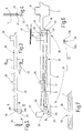
- FIG. 1 illustrates how it is used in knitting machines place.
- the needle 1 is illustrated in FIG. 1, which is also called a selection needle.
- the needle 1 has a needle body 2 as the base body carries a head 3 at one end. This is in Figure 2 separately illustrated. It has a pivoted Tongue 4, which opens the end hook 5 and closes.
- the needle 1 is in use in one in FIG direction of movement symbolized by an arrow 6 hereby movably supported.
- the needle 1 in a needle channel in which she and her two opposite flat sides 7, 8 out is.
- this first has one or several feet 11, 12 which extend from the needle body from his needle back 14 opposite Extend side away.
- the needle 1 also points to the controlled drive a selection element 16 as a selection means, which serves, the needle 1 for a certain movement active or to switch passively, i.e. to select or not to select.
- the selection element 16 is at least in the figure 1 illustrated embodiment of the needle 1 of one Recess 17 of the needle body added to the open from the side facing the needle 14 and with respect to the direction of movement of the needle 1 front and rear is each limited by a web 18, 19.
- the Selection element 16 is by an elongated rod-like Section formed, the side flanks 21, 22 with the flat sides 7,8 are aligned.
- the selection element 16 has thus the same thickness as the needle body 2.
- On its end remote from the head 3 is the selection element 16 on the needle body 2 about a pivot axis 23 pivoted.
- FIG. 3 16 This is by a hinge 20th fixed, as can be seen in particular from Figure 6 is.
- the selection element illustrated separately in FIG. 3 16 points at its adjacent to the web 19 End a disc-shaped head 24 on the in a circular penetrating the needle body 2 Bearing opening 25 is held.
- the bearing opening 25 is open to the flat sides 7, 8. Besides, it is open edge with its open edge through a connecting bridge 26 ( Figures 3 and 6) is reached.
- the connecting bridge connects the head 24 to a longitudinal web 27 the selection element 16.
- the longitudinal web 27 is on its back from the needle 14 side provided with a selection foot 29, which is at right angles from the longitudinal web 27 and to serves to pivot the selection element 16. Moreover the longitudinal web 27 carries at least one further foot 28 that stands at right angles from the longitudinal web 27 like a flag, the active by pivoting the selection element 16 or made passive, i.e. as a controlled drive can serve.
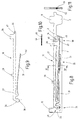
- leaf spring element 31 As can be seen from FIG. 6, there is 17 in the recess a leaf spring element 31 is provided, which has one end is integrally connected to the needle body 2.
- the Leaf spring element 31 extends from the to Hinge 20 belonging part of the needle body 2 away in Towards web 18.
- the leaf spring element 31 is biased so that it selection element 16 in Figure 6 preloaded counterclockwise.
- the needle 1 is for securing the selection element 16 in the recess 17 in situations in which the needle 1 is not installed in a needle channel, with a securing device 32 provided.
- a securing device 32 To the securing means 32 can several individual fuses 34, 35, 36 belong to the Selection element 16 e.g. form-fitting with respect to the transverse direction 33 fix.
- the individual fuse 34 is, for example, by a extending radially from the head 24
- Projection 38 is formed, as shown in FIGS. 3 and 5 can be seen.
- the projection 38 can be designed as a nose be about half the thickness of the rest of the head 24 has.
- the nose 38 can be in the center or, as in FIG. 5 illustrated to be arranged off-center.
- Corresponding a recess 39 is assigned to this nose 38, which are located in the needle body 2 directly at the bearing opening followed.
- the recess 39 is in the transverse direction 33 bounded by a side wall attached to the needle body 2, and prevents the nose 38 and thus the head 24 in one direction (in FIG. 6 from the Drawing plane) is moved out of the bearing opening 25.
- Figure 7 illustrates the positive contact of the nose 38 on the lateral boundary of the recess 39. Otherwise is the head 24 with its cylindrical outer peripheral surface on the cylindrical wall of the bearing opening 25 flat.
- the individual fuse 35 is shown in FIGS. 3, 4 and 6 can be seen.
- the longitudinal web 27 On its facing the needle body 2 Side, the longitudinal web 27 has two narrow wall-like to each other parallel extensions 41, 42 on between each other define a slot-like space 43 and smooth on the outside on the flat sides 7, 8 of the selection element 16 connect.
- the leaf spring element 31 has a width that corresponds to the distance of the extensions 41, 42 from one another, or is slightly less than this. In other words, In this area, the leaf spring 31 is made narrower than the rest.
- the leaf spring element 31 as can be seen from FIG. 6, in the intermediate space 43 to grab. With respect to the transverse direction 33 is therefore a positive connection between the leaf spring element 31 and the selection element 16 available.
- the individual fuse 36 is on that of the hinge 20 remote end of the selection element 16 is formed.
- An extension 44 belongs to the individual fuse 36 extends in the longitudinal direction away from the longitudinal web 27.
- the extension 44 has a width that is significantly smaller is than the remaining width of the longitudinal web 27. He engages in a recess 45 ( Figure 6) which over the Height of the web 18 extends. On the back of the needle 14 remote end of the web 18, this is for training a sling for the selection element 16 with provided a nose 46 overlapping the recess 17. This also delimits the recess 45.
- the individual backup prevents 34 a movement of the head 24 in a first Transverse direction 33a (out of the plane of the drawing) during the individual fuse 36 a movement in a second Transverse direction 33b (into the plane of the drawing) prevented.
- the individual fuse 35 blocks both transverse directions. Overall, this results in a captive and thus safe handling of the selection element 16 on the needle body 2.
- the needle 1 described so far works like follows:
- the leaf spring element 31 presses the selection element 16 upwards in Figure 6, i.e. away from the needle back 14, whereby a finger 47 that engages under the nose 46 the selection element 16 is formed, with the nose 46 in Facility is coming.
- the extension 44 lies loosely on one through the recess 45 recessed side surface of the web 18 on. This serves to secure the selection element laterally 16 at its front end towards 33b. His rear end is in the opposite transverse direction 33a secured in the bearing opening 25 by the projection 38, which rests on the side wall of the recess 39. In this state, the needle 1 can be handled without danger, without the selection element 16 coming out of the recess 17 could jump out. It can be used in needle channels or be removed from such.
- Figures 8 to 11 illustrate a modified Embodiment of the needle 1. This differs differ from the one described above initially in that the leaf spring element 31 on the selection element 16 is formed. For this, it is in one piece with one end connected to the longitudinal web 27. The connection is preferably provided in the vicinity of the head 24.
- the needle body 2 has the recess 17 on it facing inside in the area where the free End of the leaf spring element 31 abuts against it, one Slit (recess) 51 on the side of each an edge is limited. Engages in the slot 51 Longitudinal web (positive locking means) 52 at the free end of the leaf spring element 31 on the needle body 2 facing side is formed.
- the longitudinal web serves the lateral guidance of the leaf spring element 31 and thus at the same time the storage of the selection element 16 on captive Wise.
- the longitudinal web 52 has approximately a length that corresponds to the diameter of the head 24. If necessary, he can also be trained longer his.
- the leaf spring element 31 can also, if necessary be molded onto the needle body 2.
- the embodiment is then a selection element 16 to use according to Figures 12 and 13.
- This selection element 16 has on its side facing the needle body 2 a slot 53 which is formed by two side walls 54, 55 is limited. These are shown in Figure 13. He serves to accommodate the tapered or laterally flattened End of the leaf spring element 31st
- the individual fuse 34 and the individual fuse 36 in each case have only been designed to act unilaterally, whereby individual backup 35 is provided for support is.
- the individual fuse 36 in both transverse directions 33a, 33b in a form-fitting manner.
- a groove-like in the top of the finger 47 Recess 56 are provided, which extend in the longitudinal direction of the needle extends.
- the recess 56 is then a rib-like, provided on the underside of the nose 46, elevation extending in the longitudinal direction of the needle 57 assigned.
- the elevation 57 is designed such that it fits into the recess 56.
- the individual backup can also 34 acting in both transverse directions 33a, 33b be trained. This can be done on the head 24 on both opposite flat sides at least one, if necessary also several, dent-like Depressions 58 can be formed, each of lugs 59 are overlapped at the edge of the bearing opening 25 are trained.
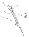
- Figure 16 illustrates a modified embodiment the needle 1 as a needle 1 '. It makes a difference different from the needle 1 described above by the Arrangement of the hinge 20 approximately in the middle of the selection element 16. This can both on the hinge means 20th as well as with its leaf spring element 31 and its both ends 61, 62 each with an individual fuse be provided as described above. To the Individual fuses 36 can be provided at both ends 61, 62 be as shown in Figure 6 for the front end of the selection element 16 is illustrated.
- the one Has selection element 16, which on the needle body 2nd is pivotally mounted, is also a safety device 32 provided that the selection element 16 positively secures to the needle body 2.
- a safety device 32 serves one or more in the transverse direction 33 effective individual backups 34, 35, 36 each in one Direction or in both transverse directions can.
- the individual fuses 34, 35, 36 are designed that the selection element 16 falls out avoided the needle body 2 in both lateral directions becomes.
- a combination of all individual fuses 34, 35, 36 is possible.
Landscapes
- Engineering & Computer Science (AREA)
- Textile Engineering (AREA)
- Knitting Machines (AREA)
Abstract
Description
- Figur 1
- eine erfindungsgemäße Nadel in perspektivischer Darstellung,
- Figur 2
- den Kopf der Nadel nach Figur 1 in Schnittdarstellung,
- Figur 3
- ein Auswahlelement der Nadel nach Figur 1 in einem anderen Maßstab, in einer schematisierten Seitenansicht,
- Figur 4
- das Auswahlelement nach Figur 3, geschnitten bei IV-IV in einem anderen Maßstab,
- Figur 5
- das Auswahlelement nach Figur 3, geschnitten bei V-V,
- Figur 6
- die Nadel nach Figur 1, in einer vergrößerten Seitenansicht,
- Figur 7
- die Nadel nach Figur 6, geschnitten bei VI-VI,
- Figur 8
- eine alternative Ausführungsform einer Nadel mit beweglichem Auswahlelement,
- Figur 9
- das bewegliche Auswahlelement der Nadel nach Figur 8,
- Figur 10
- einen Ausschnitt der Nadel nach Figur 8, in einer schematisierten Draufsicht,
- Figur 11
- die Nadel nach Figur 8, geschnitten bei XI-XI,
- Figur 12
- eine abgewandelte Ausführungsform eines Auswahlelements, in teilweise geschnittener Seitenansicht,
- Figur 13
- das Auswahlelement nach Figur 12, geschnitten bei XIII-XIII,
- Figur 14
- eine abgewandelte Ausführungsform einer erfindungsgemäßen Nadel in einer ausschnittsweisen Darstellung des Nadelkörpers und des Endes des Auswahlelements, in perspektivischer Darstellung,
- Figur 15
- eine abgewandelte Ausführungsform der Nadel in einer ausschnittsweisen Darstellung ihres Scharnierbereichs, und
- Figur 16
- eine weitere Ausführungsform einer erfindungsgemäßen Nadel, in perspektivischer Darstellung.
- 1
- Nadel
- 2
- Nadelkörper
- 3
- Kopf
- 4
- Zungen
- 5
- Haken
- 6
- Bewegungsrichtung
- 7, 8
- Flachseiten
- 11
- Fuß
- 12
- Fuß
- 14
- Nadelrücken
- 16
- Auswahlelement
- 17
- Ausnehmung
- 18, 19
- Steg
- 20
- Scharnier
- 21, 22
- Flanken
- 23
- Schwenkachse
- 24
- Kopf
- 25
- Lageröffnung
- 26
- Verbindungssteg
- 27
- Längssteg
- 28
- Auswahlfuß
- 29
- Fuß
- 31
- Blattfederlement
- 32
- Sicherungsmitttel
- 33
- Querrichtung
- 34,35,36
- Einzelsicherung
- 38
- Vorsprung
- 39
- Ausnehmung
- 41, 42
- Fortsätze
- 43
- Zwischenraum
- 44
- Fortsatz
- 45
- Ausnehmeung
- 46
- Nase
- 47
- Finger
- 51, 53
- Schlitz
- 52
- Längssteg
- 54, 55
- Seitenwand
- 56, 58
- Vertiefung
- 57
- Erhebung
- 59
- Nasen
- 61,62
- Enden
Claims (18)
- Systemteil (1), insbesondere für maschenbildende Maschinen,
mit einem Grundkörper (2), der einen zur Aufnahme in einem Nadelkanal vorgesehenen Abschnitt aufweist, der zwei einander gegenüber liegende Flachseiten (7, 8) aufweist,
mit einem Auswahlmittel (16), das dazu eingerichtet ist, dem Grundkörper (2) eine Bewegung (6) zu erteilen, wobei es mit einer Antriebseinrichtung in und außer Eingriff überführbar ist, und das mit dem Grundkörper (2) zumindest in Bewegungsrichtung (6) verbunden ist, und
mit einem Sicherungsmittel (32) zur Sicherung des Auswahlmittels (16) an dem Grundkörper (2) gegen seitliche Verlagerung in zumindest einer Querrichtung (33), die quer zu der Bewegungsrichtung (6) orientiert ist. - Systemteil nach Anspruch 1, dadurch gekennzeichnet, dass das Auswahlmittel (16) an dem Grundkörper (2) um eine Schwenkachse (23) schwenkbar gelagert ist.
- Systemteil nach Anspruch 1, dadurch gekennzeichnet, dass die Schwenkachse (23) rechtwinklig zu den Flachseiten (7, 8) angeordnet ist.
- Systemteil nach Anspruch 1, dadurch gekennzeichnet, dass die Schwenkachse (23) in Querrichtung (33) orientiert ist.
- Systemteil nach Anspruch 1, dadurch gekennzeichnet, dass das Auswahlmittel (16) ein von dem Grundkörper (2) gesondertes Auswahlelement ist, das mit dem Grundkörper (2) über ein Scharniermittel (20) verbunden ist, dessen Scharnierachse die Schwenkachse (23) ist.
- Systemteil nach Anspruch 1, dadurch gekennzeichnet, dass dem Auswahlmittel (16) ein Federmittel (31) zugeordnet ist, das das Auswahlmittel (16) in einer Schwenkrichtung federnd vorspannt.
- Systemteil nach Anspruch (1), dadurch gekennzeichnet, dass dem Systemteil (1) ein Federmittel (31) zugeordnet ist, das ein dem Systemteil (1) zugeordnetes Auswahlmittel (16) in einer Schwenkrichtung federnd vorspannt.
- Systemteil nach Anspruch 1, dadurch gekennzeichnet, dass das Auswahlmittel (16) gegen einen Anschlag (46) federnd vorgespannt ist.
- Systemteil nach Anspruch 1, dadurch gekennzeichnet, dass das Auswahlmittel (16) ein längliches Auswahlelement ist, das in einer geräumigen Ausnehmung (17) des Grundkkörpers (2) angeordnet und beweglich gelagert ist und dessen Dicke mit der Dicke des Grundkörpers (2) übereinstimmt.
- Systemteil nach Anspruch 1, dadurch gekennzeichnet, dass das Sicherungsmittel (32) wenigstens einen Vorsprung (38, 44, 57) und eine dem Vorsprung (38, 44, 57) zugeordnete Ausnehmung (39, 45,56) umfasst, wobei der Vorsprung (38, 44, 57) zumindest in Ruheposition in die Ausnehmung (39, 45, 56) greift.
- Systemteil nach Anspruch 1, dadurch gekennzeichnet, dass zu dem Sicherungsmittel (32) ein an dem Federmittel (31) vorgesehenes Formschlussmittel (52) und eine Ausnehmung (51) gehört, in die das Formschlussmittel (52) greift.
- Systemteil nach Anspruch 11, dadurch gekennzeichnet, dass die Ausnehmung (51) an dem Federmittel (31) vorgesehen ist.
- Systemteil nach Anspruch 11, dadurch gekennzeichnet, dass die Ausnehmung (51) an dem Grundkkörper (2) vorgesehen ist.
- Systemteil nach Anspruch 11, dadurch gekennzeichnet, dass die Ausnehmung (51) an dem Auswahlmittel (16) vorgesehen ist.
- Systemteil nach Anspruch 1, dadurch gekennzeichnet, dass das Federmittel (31) einstückig mit dem Auswahlmittel (16)verbunden ist.
- Systemteil nach Anspruch 9, dadurch gekennzeichnet, dass der Vorsprung (38) und die Ausnehmung (39) an dem Scharniermittel (20) vorgesehen sind.
- Systemteil nach Anspruch 9, dadurch gekennzeichnet, dass der Vorsprung (44) und die Ausnehmung (45) den der dem Scharniermittel (20) gegenüberliegenden Seite des Auswahlmittels (16) vorgesehen sind.
- Systemteil nach einem der vorhergehenden Ansprüche, dadurch gekennzeichnet, dass das Systemteil (1) eine Nadel ist.
Applications Claiming Priority (2)
| Application Number | Priority Date | Filing Date | Title |
|---|---|---|---|
| DE10111930 | 2001-03-13 | ||
| DE10111930A DE10111930C2 (de) | 2001-03-13 | 2001-03-13 | Systemteil |
Publications (2)
| Publication Number | Publication Date |
|---|---|
| EP1241287A1 true EP1241287A1 (de) | 2002-09-18 |
| EP1241287B1 EP1241287B1 (de) | 2008-03-19 |
Family
ID=7677216
Family Applications (1)
| Application Number | Title | Priority Date | Filing Date |
|---|---|---|---|
| EP02001758A Expired - Lifetime EP1241287B1 (de) | 2001-03-13 | 2002-01-25 | Systemteil |
Country Status (6)
| Country | Link |
|---|---|
| US (1) | US6705130B2 (de) |
| EP (1) | EP1241287B1 (de) |
| JP (1) | JP3610047B2 (de) |
| KR (1) | KR100476496B1 (de) |
| DE (2) | DE10111930C2 (de) |
| ES (1) | ES2300392T3 (de) |
Cited By (5)
| Publication number | Priority date | Publication date | Assignee | Title |
|---|---|---|---|---|
| EP1298238B1 (de) * | 2001-09-28 | 2005-12-07 | Groz-Beckert KG | Montage eines Auswahltelements an dem Körper eines Systemteils |
| EP1988200A1 (de) * | 2007-05-03 | 2008-11-05 | Groz-Beckert KG | Innengeführte Nadel |
| CN102242460A (zh) * | 2010-05-11 | 2011-11-16 | H.斯托尔两合公司 | 用于针织机的织针 |
| CN105544083A (zh) * | 2014-10-27 | 2016-05-04 | 雨果科恩及利伯斯两合公司 | 纺织机用针或沉降片及其制造方法 |
| EP2284308B1 (de) * | 2009-08-03 | 2017-11-08 | Groz-Beckert KG | Strickmaschinennadel mit verliersicherem Kupplungsteil |
Families Citing this family (4)
| Publication number | Priority date | Publication date | Assignee | Title |
|---|---|---|---|---|
| US7836730B1 (en) * | 2010-04-05 | 2010-11-23 | Pai Lung Machinery Mill Co., Ltd. | Circular knitting machine jacquard needle equipped with a return structure |
| KR101085264B1 (ko) | 2010-04-27 | 2011-11-22 | 파이룽 머시너리 밀 코., 엘티디. | 복원 구조물을 구비하는 원형 편물기 자카드 바늘 |
| IT202100025898A1 (it) * | 2021-10-08 | 2023-04-08 | Santoni & C Spa | Catena di trasmissione per organi di formazione maglia di una macchina circolare per maglieria e macchina circolare per maglieria comprendente tale catena di trasmissione |
| DE102023128089A1 (de) * | 2023-10-13 | 2025-04-17 | Groz-Beckert Kommanditgesellschaft | Textilmaschine, Verfahren zum Betreiben der Textilmaschine und Systemteil |
Citations (5)
| Publication number | Priority date | Publication date | Assignee | Title |
|---|---|---|---|---|
| DE2010973A1 (de) * | 1970-03-09 | 1972-01-27 | H Stoll & Co , 7410 Reutlingen | Flachstrickmaschine |
| US4434628A (en) * | 1982-04-13 | 1984-03-06 | Silver Seiko Ltd. | Knitting needle assembly |
| DE4331940C1 (de) * | 1993-09-21 | 1994-12-15 | Groz & Soehne Theodor | Umhängenadel |
| EP0908548A1 (de) * | 1997-10-08 | 1999-04-14 | Precision Fukuhara Works, Ltd. | Zweiteilige Zungennadel |
| DE19822862A1 (de) * | 1998-05-22 | 1999-11-25 | Sipra Patent Beteiligung | Strickmaschinennadel |
Family Cites Families (12)
| Publication number | Priority date | Publication date | Assignee | Title |
|---|---|---|---|---|
| US2025462A (en) * | 1933-07-13 | 1935-12-24 | Lombardi Knitting Machine Co I | Adjustable element for knitting machines |
| CH465119A (fr) * | 1966-10-25 | 1968-11-15 | Ramseier Serge | Poste de sélection des aiguilles d'une machine à tricoter |
| DE1785125B1 (de) * | 1968-08-13 | 1971-10-14 | Harry Apprich | Vorrichtung zum Herstellen einer Maschenware |
| JPS5819193Y2 (ja) * | 1979-06-13 | 1983-04-19 | 株式会社 島アイデア・センタ− | メリヤス針 |
| JPS5678896U (de) * | 1979-11-15 | 1981-06-26 | ||
| CH670464A5 (de) * | 1987-03-06 | 1989-06-15 | Sipra Patent Beteiligung | |
| DE3812240A1 (de) * | 1988-04-13 | 1989-10-26 | Alfred Buck | Steuerungs- und fuehrungseinrichtung, inbesondere fuer einschliess- und abschlagplatinen bei maschenbildenden textilmaschinen sowie einschliess- und abschlagplatine fuer solche textilmaschinen |
| DE3915684C1 (de) * | 1989-05-13 | 1990-05-23 | Theodor Groz & Soehne & Ernst Beckert Nadelfabrik Kg, 7470 Albstadt, De | |
| IT1295742B1 (it) * | 1997-02-04 | 1999-05-27 | Franco Sciacca | Metodo e attrezzatura per la selezione jacquard in una macchina tessile |
| JPH10292251A (ja) * | 1997-04-15 | 1998-11-04 | Shima Seiki Mfg Ltd | 横編機における針押さえ装置 |
| DE19720169C2 (de) * | 1997-05-14 | 1999-04-08 | Groz Beckert Kg | Auswahlplatine |
| IT1293789B1 (it) * | 1997-07-25 | 1999-03-10 | Santoni Srl | Dispositivo per la selezione degli aghi, in particolare per la selezione degli aghi del piatto in macchine circolari per |
-
2001
- 2001-03-13 DE DE10111930A patent/DE10111930C2/de not_active Expired - Fee Related
-
2002
- 2002-01-25 EP EP02001758A patent/EP1241287B1/de not_active Expired - Lifetime
- 2002-01-25 ES ES02001758T patent/ES2300392T3/es not_active Expired - Lifetime
- 2002-01-25 DE DE50211902T patent/DE50211902D1/de not_active Expired - Lifetime
- 2002-03-12 KR KR10-2002-0013143A patent/KR100476496B1/ko not_active Expired - Lifetime
- 2002-03-13 US US10/095,714 patent/US6705130B2/en not_active Expired - Lifetime
- 2002-03-13 JP JP2002067984A patent/JP3610047B2/ja not_active Expired - Lifetime
Patent Citations (5)
| Publication number | Priority date | Publication date | Assignee | Title |
|---|---|---|---|---|
| DE2010973A1 (de) * | 1970-03-09 | 1972-01-27 | H Stoll & Co , 7410 Reutlingen | Flachstrickmaschine |
| US4434628A (en) * | 1982-04-13 | 1984-03-06 | Silver Seiko Ltd. | Knitting needle assembly |
| DE4331940C1 (de) * | 1993-09-21 | 1994-12-15 | Groz & Soehne Theodor | Umhängenadel |
| EP0908548A1 (de) * | 1997-10-08 | 1999-04-14 | Precision Fukuhara Works, Ltd. | Zweiteilige Zungennadel |
| DE19822862A1 (de) * | 1998-05-22 | 1999-11-25 | Sipra Patent Beteiligung | Strickmaschinennadel |
Cited By (6)
| Publication number | Priority date | Publication date | Assignee | Title |
|---|---|---|---|---|
| EP1298238B1 (de) * | 2001-09-28 | 2005-12-07 | Groz-Beckert KG | Montage eines Auswahltelements an dem Körper eines Systemteils |
| EP1988200A1 (de) * | 2007-05-03 | 2008-11-05 | Groz-Beckert KG | Innengeführte Nadel |
| EP2284308B1 (de) * | 2009-08-03 | 2017-11-08 | Groz-Beckert KG | Strickmaschinennadel mit verliersicherem Kupplungsteil |
| CN102242460A (zh) * | 2010-05-11 | 2011-11-16 | H.斯托尔两合公司 | 用于针织机的织针 |
| CN105544083A (zh) * | 2014-10-27 | 2016-05-04 | 雨果科恩及利伯斯两合公司 | 纺织机用针或沉降片及其制造方法 |
| CN105544083B (zh) * | 2014-10-27 | 2019-04-09 | 雨果科恩及利伯斯两合公司 | 纺织机用针或沉降片及其制造方法 |
Also Published As
| Publication number | Publication date |
|---|---|
| KR100476496B1 (ko) | 2005-03-17 |
| EP1241287B1 (de) | 2008-03-19 |
| US20020129625A1 (en) | 2002-09-19 |
| DE50211902D1 (de) | 2008-04-30 |
| JP3610047B2 (ja) | 2005-01-12 |
| JP2002309468A (ja) | 2002-10-23 |
| ES2300392T3 (es) | 2008-06-16 |
| US6705130B2 (en) | 2004-03-16 |
| DE10111930A1 (de) | 2002-10-02 |
| DE10111930C2 (de) | 2003-02-27 |
| KR20020073091A (ko) | 2002-09-19 |
Similar Documents
| Publication | Publication Date | Title |
|---|---|---|
| DE69424258T3 (de) | Spannvorrichtung für einen Schneideinsatz | |
| DE7819327U1 (de) | Nadelmodul fuer eine tuftingmaschine | |
| DE4421388C2 (de) | Nadelbefestigungsvorrichtung für Wirkmaschinen | |
| EP1375721A1 (de) | Nadel mit Umhängefeder | |
| EP1241287B1 (de) | Systemteil | |
| EP1028185B1 (de) | Umhängenadel zur Maschenübertragung | |
| DE2544197C2 (de) | Aufnahmeplatte für die Schloßteile einer Strickmaschine | |
| EP0884412B1 (de) | Strickmaschine, insbesondere Flachstrickmaschine | |
| EP0596245B1 (de) | Wirknadelanordnung und zugehörige Wirknadel | |
| WO1994005858A1 (de) | Vorrichtung zum befestigen einer schiene | |
| DE20103921U1 (de) | Werkzeug zur spanenden Feinarbeitung von Werkstücken | |
| WO2005095703A1 (de) | Geprägte tuftingnadel | |
| EP0402587B1 (de) | Strickwerkzeug für Strickmaschinen | |
| EP0244656B1 (de) | Einspannvorrichtung für Nadeln | |
| DE10148196C1 (de) | Systemteil | |
| DE102004033929B3 (de) | Werkzeug zur Verwendung in einer Werkzeugmaschine | |
| DE907491C (de) | Naehmaschinennadelklemme | |
| DE2926928C2 (de) | "Mustergetriebe für Kettenwirkmaschinen o.dgl. | |
| DE1685063C3 (de) | Doppelkettenstich-Nähmaschine | |
| EP2428601A1 (de) | Legenadelanordnung für eine Jacquard-Legebarre | |
| DE3600621C1 (de) | Zungennadel fuer Textilmaschinen | |
| DE102010044673B4 (de) | Wirkwerkzeugbarren-Reparaturset und Wirkwerkzeugbarre | |
| DE2462299C3 (de) | Klappanker-Relais | |
| DE3539346C2 (de) | Bohrvorrichtung an einer Stickmaschine | |
| DE102010032997A1 (de) | Legenadelanordnung einer Wirkmaschine, insbesondere einer Raschelmaschine |
Legal Events
| Date | Code | Title | Description |
|---|---|---|---|
| PUAI | Public reference made under article 153(3) epc to a published international application that has entered the european phase |
Free format text: ORIGINAL CODE: 0009012 |
|
| AK | Designated contracting states |
Kind code of ref document: A1 Designated state(s): AT BE CH CY DE DK ES FI FR GB GR IE IT LI LU MC NL PT SE TR |
|
| AX | Request for extension of the european patent |
Free format text: AL;LT;LV;MK;RO;SI |
|
| 17P | Request for examination filed |
Effective date: 20030225 |
|
| AKX | Designation fees paid |
Designated state(s): DE ES FR GB IT |
|
| 17Q | First examination report despatched |
Effective date: 20041215 |
|
| GRAP | Despatch of communication of intention to grant a patent |
Free format text: ORIGINAL CODE: EPIDOSNIGR1 |
|
| GRAS | Grant fee paid |
Free format text: ORIGINAL CODE: EPIDOSNIGR3 |
|
| GRAA | (expected) grant |
Free format text: ORIGINAL CODE: 0009210 |
|
| AK | Designated contracting states |
Kind code of ref document: B1 Designated state(s): DE ES FR GB IT |
|
| REG | Reference to a national code |
Ref country code: GB Ref legal event code: FG4D Free format text: NOT ENGLISH |
|
| GBT | Gb: translation of ep patent filed (gb section 77(6)(a)/1977) |
Effective date: 20080319 |
|
| REF | Corresponds to: |
Ref document number: 50211902 Country of ref document: DE Date of ref document: 20080430 Kind code of ref document: P |
|
| REG | Reference to a national code |
Ref country code: ES Ref legal event code: FG2A Ref document number: 2300392 Country of ref document: ES Kind code of ref document: T3 |
|
| ET | Fr: translation filed | ||
| PLBE | No opposition filed within time limit |
Free format text: ORIGINAL CODE: 0009261 |
|
| STAA | Information on the status of an ep patent application or granted ep patent |
Free format text: STATUS: NO OPPOSITION FILED WITHIN TIME LIMIT |
|
| 26N | No opposition filed |
Effective date: 20081222 |
|
| REG | Reference to a national code |
Ref country code: FR Ref legal event code: PLFP Year of fee payment: 14 |
|
| PGFP | Annual fee paid to national office [announced via postgrant information from national office to epo] |
Ref country code: ES Payment date: 20150128 Year of fee payment: 14 |
|
| PGFP | Annual fee paid to national office [announced via postgrant information from national office to epo] |
Ref country code: FR Payment date: 20150122 Year of fee payment: 14 |
|
| REG | Reference to a national code |
Ref country code: FR Ref legal event code: ST Effective date: 20160930 |
|
| PG25 | Lapsed in a contracting state [announced via postgrant information from national office to epo] |
Ref country code: FR Free format text: LAPSE BECAUSE OF NON-PAYMENT OF DUE FEES Effective date: 20160201 |
|
| REG | Reference to a national code |
Ref country code: ES Ref legal event code: FD2A Effective date: 20170224 |
|
| PG25 | Lapsed in a contracting state [announced via postgrant information from national office to epo] |
Ref country code: ES Free format text: LAPSE BECAUSE OF NON-PAYMENT OF DUE FEES Effective date: 20160126 |
|
| PGFP | Annual fee paid to national office [announced via postgrant information from national office to epo] |
Ref country code: DE Payment date: 20210131 Year of fee payment: 20 Ref country code: GB Payment date: 20210113 Year of fee payment: 20 |
|
| PGFP | Annual fee paid to national office [announced via postgrant information from national office to epo] |
Ref country code: IT Payment date: 20201211 Year of fee payment: 20 |
|
| REG | Reference to a national code |
Ref country code: DE Ref legal event code: R071 Ref document number: 50211902 Country of ref document: DE |
|
| REG | Reference to a national code |
Ref country code: GB Ref legal event code: PE20 Expiry date: 20220124 |
|
| PG25 | Lapsed in a contracting state [announced via postgrant information from national office to epo] |
Ref country code: GB Free format text: LAPSE BECAUSE OF EXPIRATION OF PROTECTION Effective date: 20220124 |