EP1223323A2 - Vorrichtung und Verfahren zur Steuerung eines Fahrzeugs für die Reinigung der Abgase einer Brennkraftmaschine - Google Patents
Vorrichtung und Verfahren zur Steuerung eines Fahrzeugs für die Reinigung der Abgase einer Brennkraftmaschine Download PDFInfo
- Publication number
- EP1223323A2 EP1223323A2 EP02000896A EP02000896A EP1223323A2 EP 1223323 A2 EP1223323 A2 EP 1223323A2 EP 02000896 A EP02000896 A EP 02000896A EP 02000896 A EP02000896 A EP 02000896A EP 1223323 A2 EP1223323 A2 EP 1223323A2
- Authority
- EP
- European Patent Office
- Prior art keywords
- engine
- vehicle
- exhaust
- internal combustion
- combustion engine
- Prior art date
- Legal status (The legal status is an assumption and is not a legal conclusion. Google has not performed a legal analysis and makes no representation as to the accuracy of the status listed.)
- Granted
Links
Images

Classifications
-
- B—PERFORMING OPERATIONS; TRANSPORTING
- B60—VEHICLES IN GENERAL
- B60W—CONJOINT CONTROL OF VEHICLE SUB-UNITS OF DIFFERENT TYPE OR DIFFERENT FUNCTION; CONTROL SYSTEMS SPECIALLY ADAPTED FOR HYBRID VEHICLES; ROAD VEHICLE DRIVE CONTROL SYSTEMS FOR PURPOSES NOT RELATED TO THE CONTROL OF A PARTICULAR SUB-UNIT
- B60W10/00—Conjoint control of vehicle sub-units of different type or different function
- B60W10/04—Conjoint control of vehicle sub-units of different type or different function including control of propulsion units
- B60W10/06—Conjoint control of vehicle sub-units of different type or different function including control of propulsion units including control of combustion engines
-
- B—PERFORMING OPERATIONS; TRANSPORTING
- B60—VEHICLES IN GENERAL
- B60K—ARRANGEMENT OR MOUNTING OF PROPULSION UNITS OR OF TRANSMISSIONS IN VEHICLES; ARRANGEMENT OR MOUNTING OF PLURAL DIVERSE PRIME-MOVERS IN VEHICLES; AUXILIARY DRIVES FOR VEHICLES; INSTRUMENTATION OR DASHBOARDS FOR VEHICLES; ARRANGEMENTS IN CONNECTION WITH COOLING, AIR INTAKE, GAS EXHAUST OR FUEL SUPPLY OF PROPULSION UNITS IN VEHICLES
- B60K6/00—Arrangement or mounting of plural diverse prime-movers for mutual or common propulsion, e.g. hybrid propulsion systems comprising electric motors and internal combustion engines ; Control systems therefor, i.e. systems controlling two or more prime movers, or controlling one of these prime movers and any of the transmission, drive or drive units Informative references: mechanical gearings with secondary electric drive F16H3/72; arrangements for handling mechanical energy structurally associated with the dynamo-electric machine H02K7/00; machines comprising structurally interrelated motor and generator parts H02K51/00; dynamo-electric machines not otherwise provided for in H02K see H02K99/00
- B60K6/20—Arrangement or mounting of plural diverse prime-movers for mutual or common propulsion, e.g. hybrid propulsion systems comprising electric motors and internal combustion engines ; Control systems therefor, i.e. systems controlling two or more prime movers, or controlling one of these prime movers and any of the transmission, drive or drive units Informative references: mechanical gearings with secondary electric drive F16H3/72; arrangements for handling mechanical energy structurally associated with the dynamo-electric machine H02K7/00; machines comprising structurally interrelated motor and generator parts H02K51/00; dynamo-electric machines not otherwise provided for in H02K see H02K99/00 the prime-movers consisting of electric motors and internal combustion engines, e.g. HEVs
- B60K6/42—Arrangement or mounting of plural diverse prime-movers for mutual or common propulsion, e.g. hybrid propulsion systems comprising electric motors and internal combustion engines ; Control systems therefor, i.e. systems controlling two or more prime movers, or controlling one of these prime movers and any of the transmission, drive or drive units Informative references: mechanical gearings with secondary electric drive F16H3/72; arrangements for handling mechanical energy structurally associated with the dynamo-electric machine H02K7/00; machines comprising structurally interrelated motor and generator parts H02K51/00; dynamo-electric machines not otherwise provided for in H02K see H02K99/00 the prime-movers consisting of electric motors and internal combustion engines, e.g. HEVs characterised by the architecture of the hybrid electric vehicle
- B60K6/44—Series-parallel type
- B60K6/445—Differential gearing distribution type
-
- F—MECHANICAL ENGINEERING; LIGHTING; HEATING; WEAPONS; BLASTING
- F01—MACHINES OR ENGINES IN GENERAL; ENGINE PLANTS IN GENERAL; STEAM ENGINES
- F01N—GAS-FLOW SILENCERS OR EXHAUST APPARATUS FOR MACHINES OR ENGINES IN GENERAL; GAS-FLOW SILENCERS OR EXHAUST APPARATUS FOR INTERNAL COMBUSTION ENGINES
- F01N13/00—Exhaust or silencing apparatus characterised by constructional features ; Exhaust or silencing apparatus, or parts thereof, having pertinent characteristics not provided for in, or of interest apart from, groups F01N1/00 - F01N5/00, F01N9/00, F01N11/00
- F01N13/009—Exhaust or silencing apparatus characterised by constructional features ; Exhaust or silencing apparatus, or parts thereof, having pertinent characteristics not provided for in, or of interest apart from, groups F01N1/00 - F01N5/00, F01N9/00, F01N11/00 having two or more separate purifying devices arranged in series
-
- F—MECHANICAL ENGINEERING; LIGHTING; HEATING; WEAPONS; BLASTING
- F01—MACHINES OR ENGINES IN GENERAL; ENGINE PLANTS IN GENERAL; STEAM ENGINES
- F01N—GAS-FLOW SILENCERS OR EXHAUST APPARATUS FOR MACHINES OR ENGINES IN GENERAL; GAS-FLOW SILENCERS OR EXHAUST APPARATUS FOR INTERNAL COMBUSTION ENGINES
- F01N3/00—Exhaust or silencing apparatus having means for purifying, rendering innocuous, or otherwise treating exhaust
- F01N3/08—Exhaust or silencing apparatus having means for purifying, rendering innocuous, or otherwise treating exhaust for rendering innocuous
- F01N3/0807—Exhaust or silencing apparatus having means for purifying, rendering innocuous, or otherwise treating exhaust for rendering innocuous by using absorbents or adsorbents
- F01N3/0814—Exhaust or silencing apparatus having means for purifying, rendering innocuous, or otherwise treating exhaust for rendering innocuous by using absorbents or adsorbents combined with catalytic converters, e.g. NOx absorption/storage reduction catalysts
-
- F—MECHANICAL ENGINEERING; LIGHTING; HEATING; WEAPONS; BLASTING
- F01—MACHINES OR ENGINES IN GENERAL; ENGINE PLANTS IN GENERAL; STEAM ENGINES
- F01N—GAS-FLOW SILENCERS OR EXHAUST APPARATUS FOR MACHINES OR ENGINES IN GENERAL; GAS-FLOW SILENCERS OR EXHAUST APPARATUS FOR INTERNAL COMBUSTION ENGINES
- F01N3/00—Exhaust or silencing apparatus having means for purifying, rendering innocuous, or otherwise treating exhaust
- F01N3/08—Exhaust or silencing apparatus having means for purifying, rendering innocuous, or otherwise treating exhaust for rendering innocuous
- F01N3/0807—Exhaust or silencing apparatus having means for purifying, rendering innocuous, or otherwise treating exhaust for rendering innocuous by using absorbents or adsorbents
- F01N3/0828—Exhaust or silencing apparatus having means for purifying, rendering innocuous, or otherwise treating exhaust for rendering innocuous by using absorbents or adsorbents characterised by the absorbed or adsorbed substances
- F01N3/0835—Hydrocarbons
-
- F—MECHANICAL ENGINEERING; LIGHTING; HEATING; WEAPONS; BLASTING
- F01—MACHINES OR ENGINES IN GENERAL; ENGINE PLANTS IN GENERAL; STEAM ENGINES
- F01N—GAS-FLOW SILENCERS OR EXHAUST APPARATUS FOR MACHINES OR ENGINES IN GENERAL; GAS-FLOW SILENCERS OR EXHAUST APPARATUS FOR INTERNAL COMBUSTION ENGINES
- F01N3/00—Exhaust or silencing apparatus having means for purifying, rendering innocuous, or otherwise treating exhaust
- F01N3/08—Exhaust or silencing apparatus having means for purifying, rendering innocuous, or otherwise treating exhaust for rendering innocuous
- F01N3/10—Exhaust or silencing apparatus having means for purifying, rendering innocuous, or otherwise treating exhaust for rendering innocuous by thermal or catalytic conversion of noxious components of exhaust
- F01N3/18—Exhaust or silencing apparatus having means for purifying, rendering innocuous, or otherwise treating exhaust for rendering innocuous by thermal or catalytic conversion of noxious components of exhaust characterised by methods of operation; Control
- F01N3/20—Exhaust or silencing apparatus having means for purifying, rendering innocuous, or otherwise treating exhaust for rendering innocuous by thermal or catalytic conversion of noxious components of exhaust characterised by methods of operation; Control specially adapted for catalytic conversion ; Methods of operation or control of catalytic converters
- F01N3/2006—Periodically heating or cooling catalytic reactors, e.g. at cold starting or overheating
-
- F—MECHANICAL ENGINEERING; LIGHTING; HEATING; WEAPONS; BLASTING
- F02—COMBUSTION ENGINES; HOT-GAS OR COMBUSTION-PRODUCT ENGINE PLANTS
- F02D—CONTROLLING COMBUSTION ENGINES
- F02D41/00—Electrical control of supply of combustible mixture or its constituents
- F02D41/02—Circuit arrangements for generating control signals
- F02D41/021—Introducing corrections for particular conditions exterior to the engine
- F02D41/0235—Introducing corrections for particular conditions exterior to the engine in relation with the state of the exhaust gas treating apparatus
-
- F—MECHANICAL ENGINEERING; LIGHTING; HEATING; WEAPONS; BLASTING
- F02—COMBUSTION ENGINES; HOT-GAS OR COMBUSTION-PRODUCT ENGINE PLANTS
- F02D—CONTROLLING COMBUSTION ENGINES
- F02D41/00—Electrical control of supply of combustible mixture or its constituents
- F02D41/02—Circuit arrangements for generating control signals
- F02D41/04—Introducing corrections for particular operating conditions
- F02D41/06—Introducing corrections for particular operating conditions for engine starting or warming up
- F02D41/062—Introducing corrections for particular operating conditions for engine starting or warming up for starting
-
- F—MECHANICAL ENGINEERING; LIGHTING; HEATING; WEAPONS; BLASTING
- F02—COMBUSTION ENGINES; HOT-GAS OR COMBUSTION-PRODUCT ENGINE PLANTS
- F02N—STARTING OF COMBUSTION ENGINES; STARTING AIDS FOR SUCH ENGINES, NOT OTHERWISE PROVIDED FOR
- F02N11/00—Starting of engines by means of electric motors
- F02N11/08—Circuits or control means specially adapted for starting of engines
- F02N11/0814—Circuits or control means specially adapted for starting of engines comprising means for controlling automatic idle-start-stop
- F02N11/0818—Conditions for starting or stopping the engine or for deactivating the idle-start-stop mode
-
- Y—GENERAL TAGGING OF NEW TECHNOLOGICAL DEVELOPMENTS; GENERAL TAGGING OF CROSS-SECTIONAL TECHNOLOGIES SPANNING OVER SEVERAL SECTIONS OF THE IPC; TECHNICAL SUBJECTS COVERED BY FORMER USPC CROSS-REFERENCE ART COLLECTIONS [XRACs] AND DIGESTS
- Y02—TECHNOLOGIES OR APPLICATIONS FOR MITIGATION OR ADAPTATION AGAINST CLIMATE CHANGE
- Y02A—TECHNOLOGIES FOR ADAPTATION TO CLIMATE CHANGE
- Y02A50/00—TECHNOLOGIES FOR ADAPTATION TO CLIMATE CHANGE in human health protection, e.g. against extreme weather
- Y02A50/20—Air quality improvement or preservation, e.g. vehicle emission control or emission reduction by using catalytic converters
-
- Y—GENERAL TAGGING OF NEW TECHNOLOGICAL DEVELOPMENTS; GENERAL TAGGING OF CROSS-SECTIONAL TECHNOLOGIES SPANNING OVER SEVERAL SECTIONS OF THE IPC; TECHNICAL SUBJECTS COVERED BY FORMER USPC CROSS-REFERENCE ART COLLECTIONS [XRACs] AND DIGESTS
- Y02—TECHNOLOGIES OR APPLICATIONS FOR MITIGATION OR ADAPTATION AGAINST CLIMATE CHANGE
- Y02T—CLIMATE CHANGE MITIGATION TECHNOLOGIES RELATED TO TRANSPORTATION
- Y02T10/00—Road transport of goods or passengers
- Y02T10/10—Internal combustion engine [ICE] based vehicles
- Y02T10/12—Improving ICE efficiencies
-
- Y—GENERAL TAGGING OF NEW TECHNOLOGICAL DEVELOPMENTS; GENERAL TAGGING OF CROSS-SECTIONAL TECHNOLOGIES SPANNING OVER SEVERAL SECTIONS OF THE IPC; TECHNICAL SUBJECTS COVERED BY FORMER USPC CROSS-REFERENCE ART COLLECTIONS [XRACs] AND DIGESTS
- Y02—TECHNOLOGIES OR APPLICATIONS FOR MITIGATION OR ADAPTATION AGAINST CLIMATE CHANGE
- Y02T—CLIMATE CHANGE MITIGATION TECHNOLOGIES RELATED TO TRANSPORTATION
- Y02T10/00—Road transport of goods or passengers
- Y02T10/10—Internal combustion engine [ICE] based vehicles
- Y02T10/40—Engine management systems
-
- Y—GENERAL TAGGING OF NEW TECHNOLOGICAL DEVELOPMENTS; GENERAL TAGGING OF CROSS-SECTIONAL TECHNOLOGIES SPANNING OVER SEVERAL SECTIONS OF THE IPC; TECHNICAL SUBJECTS COVERED BY FORMER USPC CROSS-REFERENCE ART COLLECTIONS [XRACs] AND DIGESTS
- Y02—TECHNOLOGIES OR APPLICATIONS FOR MITIGATION OR ADAPTATION AGAINST CLIMATE CHANGE
- Y02T—CLIMATE CHANGE MITIGATION TECHNOLOGIES RELATED TO TRANSPORTATION
- Y02T10/00—Road transport of goods or passengers
- Y02T10/60—Other road transportation technologies with climate change mitigation effect
- Y02T10/62—Hybrid vehicles
-
- Y—GENERAL TAGGING OF NEW TECHNOLOGICAL DEVELOPMENTS; GENERAL TAGGING OF CROSS-SECTIONAL TECHNOLOGIES SPANNING OVER SEVERAL SECTIONS OF THE IPC; TECHNICAL SUBJECTS COVERED BY FORMER USPC CROSS-REFERENCE ART COLLECTIONS [XRACs] AND DIGESTS
- Y10—TECHNICAL SUBJECTS COVERED BY FORMER USPC
- Y10S—TECHNICAL SUBJECTS COVERED BY FORMER USPC CROSS-REFERENCE ART COLLECTIONS [XRACs] AND DIGESTS
- Y10S903/00—Hybrid electric vehicles, HEVS
- Y10S903/902—Prime movers comprising electrical and internal combustion motors
- Y10S903/903—Prime movers comprising electrical and internal combustion motors having energy storing means, e.g. battery, capacitor
Definitions
- the present invention relates to an apparatus and a method for controlling a vehicle such that an internal combustion engine of the vehicle is controlled so as to reduce harmful exhaust gas components to be emitted into the atmosphere.
- engine Internal combustion engines (hereinafter referred to as "engine") of recent design for automotive or other vehicles are equipped in their exhaust system with a catalytic converter incorporating a catalyst such as a three-way catalyst, which is capable of inducing mutual reaction of harmful components NOx, HC and CO contained in an exhaust gas emission from the engines, to convert those harmful components into non-harmful components N 2 , CO 2 and H 2 O, for the purpose of preventing the harmful components from being released into the atmosphere, to meet a need of protecting the atmospheric environment.
- a catalytic converter incorporating a catalyst such as a three-way catalyst, which is capable of inducing mutual reaction of harmful components NOx, HC and CO contained in an exhaust gas emission from the engines, to convert those harmful components into non-harmful components N 2 , CO 2 and H 2 O, for the purpose of preventing the harmful components from being released into the atmosphere, to meet a need of protecting the atmospheric environment.
- exhaust-emission purifying catalyst for purifying the exhaust gas emission from the engines does not become active until the catalyst has been sufficiently warmed up by the exhaust gas up to a temperature not lower than a certain activation threshold.
- exhaust-emission purifying catalyst for purifying the exhaust gas emission from the engines does not become active until the catalyst has been sufficiently warmed up by the exhaust gas up to a temperature not lower than a certain activation threshold.
- the engine is inevitably operated with its catalyst held in a non-active state for some time immediately after the starting of the engine in a cold state to start running the vehicle.
- the engine is kept in the operated state once the vehicle running is started, so that a problem of the engine operation with its catalyst in its non-active state is encountered for only a relatively short time immediately after the starting of the vehicle running.
- economy-running-system vehicles and hybrid vehicles are attracting more and more attention, in view of the recent growing requirement for saving fuel resources as well as the protection of the atmospheric environment.
- the economy-running-system vehicles are arranged to temporarily stop the engine upon stopping of the running vehicle due to stop signals or a traffic jam.
- the hybrid vehicles are adapted to selective use an engine and an electric motor as the drive power source, as needed depending upon the specific running condition of the vehicle.
- the engine may be temporarily stopped according to an economy-running control or hybrid control, before the exhaust-emission purifying catalyst has been sufficiently warmed up after the starting of the engine in a cold state.
- the exhaust-emission catalyst can be warmed up to a temperature not lower than the activation threshold, owing to the inhibition of the temporary stop of the engine until the catalyst has been sufficiently warmed up.
- the engine may be again temporarily stopped according to the economy-running control or hybrid control, and the temperature of the catalyst may be lowered down to the activation threshold, if the duration of the temporary stop of the engine is relatively long. Namely, there still exists a risk that the temporary stop of the engine for a long time causes a gradual drop of the catalyst temperature down to the activation threshold or lower.
- HC-emission preventing means including an HC adsorbent which is accommodated in a container disposed upstream of the catalytic converter accommodated in another container, or accommodated in the container of the catalytic converter such that a layer of the HC adsorbent is superposed on a layer of the three-way catalyst.
- the HC adsorbent of the HC-emission preventing means temporarily adsorbs and holds HC to be emitted in a large amount immediately after the starting of the engine, until the exhaust-emission purifying catalyst has been sufficiently warmed up and become active.
- the catalyst After the catalyst has become active as a result of the warming-up of the catalytic converter, the catalyst functions to remove the HC that is released due to a loss of the HC adsorption ability of the HC adsorbent which has been heated by the exhaust gas emitted from the engine.
- the temperature of the HC oxidizing catalyst is lowered to a point slightly lower than its activation threshold due to a temporary stop of the engine, subsequent re-starting of the engine may cause the temperature of the HC adsorbent of the HC-emission preventing means to become higher than an upper limit above which the HC adsorbent is not capable of adsorbing the HC, while the HC oxidizing catalyst is still in a non-active state.
- the present invention was made in view of the drawback discussed above. It is therefore a first object of the present invention to provide a method of controlling a vehicle, which is improved to minimize the above-described problems associated with a temporary stop of an engine of an economy-running-system vehicle or a hybrid vehicle and a consequent change of the temperature of an exhaust-emission purifying catalyst of the engine.
- a second object of the invention is to provide an apparatus for controlling a vehicle, which is improved to minimize the problems indicated above.
- the first object indicated above may be achieved according to a first aspect of the present invention, which provides a method of controlling a vehicle including an internal combustion engine such that the internal combustion engine is controlled so as to purify an exhaust emission from the internal combustion engine with an exhaust-emission purifying catalyst disposed in an exhaust system of the internal combustion engine, and such that the engine is brought into a temporary engine-stop state while a predetermined condition of the vehicle is satisfied, characterized in that the internal combustion engine is operated when a temperature of the exhaust-emission purifying catalyst has been lowered below a predetermined lower limit threshold, even while the predetermined condition of the vehicle is still satisfied, the catalyst maintaining an exhaust-emission purifying ability at a temperature above the predetermined lower limit threshold.
- the second object indicated above may be achieved according to a second aspect of the invention, which provides an apparatus for controlling a vehicle including an internal combustion engine such that the internal combustion engine is controlled so as to purify an exhaust emission from the internal combustion engine with an exhaust-emission purifying catalyst disposed in an exhaust system of the engine, and such that the engine is brought into a temporary engine-stop state while a predetermined condition of the vehicle is satisfied, characterized by comprising a controller operable to operate the internal combustion engine when a temperature of the exhaust-emission purifying catalyst has been lowered below a predetermined lower limit threshold, even while the predetermined condition of the vehicle is still satisfied, the catalyst maintaining an exhaust-emission purifying ability at a temperature above the predetermined lower limit threshold.
- the vehicle control method and apparatus of the present invention described above are arranged to operate the internal combustion engine, even while the predetermined condition of the vehicle is still satisfied, if the temperature of the exhaust-emission purifying catalyst has been lowered below the predetermined lower limit threshold above which the catalyst maintains the exhaust-emission purifying ability. According to the present vehicle control method and apparatus, therefore, the internal combustion engine is operated to prevent an excessive drop of the temperature of the catalyst due to the temporary stop of the engine according to the economy-running control or hybrid control, for thereby preventing a loss of the exhaust-emission purifying ability of the catalyst due to such an excessive temperature drop of the catalyst.
- the present vehicle control method and apparatus prevent the temperature drop of the exhaust-emission purifying catalyst slightly below the activation lower limit, it is possible to avoid an undesirable situation in which the exhaust-emission purifying catalyst and an HC adsorbent if used in combination of the catalyst are both unable to function.
- the internal combustion engine is restored to the temporary engine-stop state, if the predetermined condition of the vehicle is still satisfied, when the temperature of the exhaust-emission purifying catalyst has been raised to a predetermined upper limit threshold higher than the lower limit threshold, as a result of the operation of the internal combustion engine while the predetermined condition of the vehicle is satisfied.
- the operation of the internal combustion engine after being restarted while the predetermined condition of the vehicle is satisfied is controlled so as to effectively heat the exhaust-emission purifying catalyst.
- the operation of the internal combustion engine while the predetermined condition of the vehicle is satisfied is effected with a delayed ignition timing of the engine, to promote the heating of the exhaust-emission purifying catalyst.
- the vehicle control method and apparatus of this invention are suitably applicable to an economy-running-system vehicle or a hybrid vehicle.
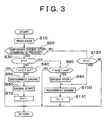
- Fig. 3 there is illustrated the engine control routine executed according to one embodiment of the present invention, to control an engine of an automotive vehicle for a time period between two points of time t2 and t4 and a time period between two points of time t4 and t6, during a running of the vehicle, as indicated in Fig. 1.
- This engine control routine is executed according to an engine control program which is stored, together with various other control programs, in a vehicle control apparatus including a microcomputer (not shown) well known in the art of controlling an economy-running-system vehicle or a hybrid vehicle.
- This engine control routine is initiated when the vehicle control apparatus is turned on.
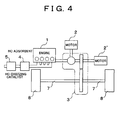
- a hybrid vehicle to which one embodiment of the vehicle control apparatus is adopted is schematically shown in Fig. 4.
- the hybrid vehicle has an internal combustion engine (hereinafter referred to as "engine") 1 and two electric motors 2 and 2'.
- a driving power of the engine 1 and/or the electric motors 2, 2' is transmitted to a wheel 8 via a drive system 3 and a driveshaft 7.
- the motor 2 mainly functions as an electric generator and the motor 2' mainly functions as an electric motor.
- step S10 The engine control routine is initiated with step S10 to read in various kinds of data used to control the engine 1, such as an engine operation command and a temperature Tcc of the exhaust-emission purifying catalyst (HC oxidizing catalyst 5 is shown as the exhaust-emission purifying catalyst in Fig. 4). Then, step S20 is implemented to determine whether or not a temporary engine-stop command is present. If an affirmative decision (YES) is obtained in step S20, the control flow goes to step S30 to determine whether a flag F is set at "1". This flag is initially reset to "0" and is set to "1" in step S70 (described below), so that a negative decision (NO) is obtained in step S30 immediately after the initiation of the present routine, and the control flow goes to step S40.
- YES affirmative decision
- step S30 determine whether a flag F is set at "1". This flag is initially reset to "0" and is set to "1" in step S70 (described below), so that a negative decision (NO) is obtained in
- Step S40 is provided to determine whether the temperature Tcc of the exhaust-emission purifying catalyst 5 is equal to or higher than a predetermined lower limit threshold Tcc1, which is slightly higher than an activation lower limit Tcc0 above which the catalyst 5 is active. If an affirmative decision (YES) is obtained in step S40, it indicates that a control of the engine 1 according to the present engine control routine is not presently necessary. In this case, the control flow immediately returns back to step S10 in which updated data are read in. If a negative decision (NO) is obtained in step S40, the control flow goes to step S50.
- a predetermined lower limit threshold Tcc1 which is slightly higher than an activation lower limit Tcc0 above which the catalyst 5 is active.
- Step S50 is provided to disconnect the engine 1 from the other part of the drive system 3 (shown in Fig. 4), which includes a transmission.
- Step S50 is followed by step S60 to restart the engine 1 so that the engine 1 is placed in an operating state.
- This engine operation while the temporary engine-stop command is present is effected not to produce a drive force for driving the vehicle, but to heat the exhaust-emission purifying catalyst 5 with the exhaust gas.
- the engine 1 is controlled with a delayed ignition timing, for maximizing a rise of the temperature of the exhaust gas while reducing the drive force.
- the engine operation in the presence of the temporary engine-stop command is referred to as "heating operation of the engine", where appropriate.
- the control flow goes to step S70 to set the flag F to "1", and returns back to step S10.
- step S70 After step S70 is implemented, the flag F is set at "1", so that an affirmative decision (YES) is obtained in step S30, and the control flow goes to step S80 to determine whether the temperature Tcc is equal to or higher than a predetermined upper limit threshold Tcc2 which is determined to provide an optimum compromise between the frequency and time duration of the heating operation of the engine 1. If a negative decision (NO) is obtained in step S80, the control flow returns back to step S10.
- the heating operations of the engine 1 are effected during a time period between two points t2 and t4 and a time period between two points t4 and t5, as indicated in Fig. 1, by repeated implementation of steps S10, S20, S30 and S80.
- step S80 When the temperature of the exhaust-emission purifying catalyst 5 has reached the upper limit threshold Tcc2 as a result of the heating operation of the engine 1 to heat the catalyst 5, an affirmative decision (YES) is obtained in step S80, and the control flow goes to step S90 to stop the engine 1, for restoring the engine 1 to the temporary engine-stop state. Step S100 is then implemented to re-connect the engine 1 to the other part of the drive system 3, that is, to cancel the disconnection of the engine 1 effected in step S50. Then, the control flow goes to step S110 to reset the flag F to "0".
- step S20 When the temporary engine-stop command is removed at any point of time during the present engine control routine, a negative decision (NO) is obtained in step S20, and the control flow goes to step S120 to determine whether the flag is set at "1". If the engine 1 is in the heating operation to heat the catalyst 5, the flag F1 is set at "1". In this case, the control flow goes to step S100 to re-connect the engine 1 to the other part of the drive system 3, and to step S110 to reset the flag F to "0".
- the negative decision (NO) is obtained in both of the steps S20 and S120. In this case, the heating operation of the engine 1 is not effected.
- a temporary engine-stop command is generated to temporarily stop the engine at a point of time t1 according to the economy-running control or hybrid control when the vehicle is stopped at a traffic signal after starting of the vehicle with the engine 1 held in a cold state.
- the temperature of the exhaust-emission purifying catalyst such as a three-way catalyst 5 disposed in the exhaust system of the engine was in the process of a relatively slow rise, and the temperature at the point of time t1 is sufficiently higher than the activation lower limit Tcc0 above which the catalyst 5 is capable of performing its intended exhaust-emission purifying function.
- the temporary stop of the engine 1 at the point of time t1 will initiate a drop of the temperature Tcc of the exhaust-emission purifying catalyst 5, and the continuation of the temporary stop of the engine 1 will cause the temperature Tcc to be gradually lowered down to a level close to the activation lower limit Tcc0.
- the present embodiment is arranged to initiate a heating operation of the engine 1 at the point of time t2, that is, when the temperature Tcc has been lowered to the predetermined lower limit threshold Tcc1 slightly higher than the activation lower limit Tcc0, even in the presence of the temporary engine-stop command, so that the engine 1 is operated for the purpose of maintaining the active state of the exhaust-emission purifying catalyst 5.
- This heating operation of the engine 1 for maintaining the catalyst 5 in the active state in the presence of the temporary engine-stop command is controlled by a suitable known engine control device (not shown), preferably in a manner suitable for heating the exhaust-emission purifying catalyst 5, that is, so as to effectively raise the temperature of the exhaust gas while restricting the drive force of the engine 1, for instance, by retarding the ignition timing of the engine 1.
- the temperature Tcc of the exhaust-emission purifying catalyst 5 rises to the upper limit threshold Tcc2 at a point of time t3 a certain time after the point of time t2.
- the engine 1 is restored to the temporary engine-stop state if the temporary engine-stop command is still present.
- the termination of the heating operation of the engine 1 at the point of time t3 causes a subsequent drop of the temperature Tcc of the catalyst 5, eventually down to the lower limit threshold Tcc1 at the point of time t4 at which the temporary engine-stop command is still present. Consequently, the heating operation of the engine 1 is again initiated at the point of time t4, and is terminated at a point of time t5 so that the engine 1 is restored to the temporary engine-stop state.
- the temporary stop is terminated to resume a normal operation of the engine 1 upon removal of the temporary engine-stop command at the point of time t6, namely, upon generation of a normal engine-operation command at the point of time t6.
- the present engine control routine prevents a drop of the temperature Tcc of the exhaust-emission purifying catalyst 5, into a temperature range just below the activation lower limit Tcc0 above which the catalyst 5 remains in an active state.
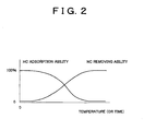
- the HC adsorption ability of an HC adsorbent 4 and the HC removing ability of the exhaust-emission purifying catalyst 5 (which is an HC oxidizing catalyst such as a three-way catalyst) change with a change of the temperatures of the HC adsorbent 4 and the catalyst 5, as shown in the graph of Fig. 2 in which the HC adsorption ability and HC removing ability are taken along the ordinate while the temperatures is taken along the abscissa.
- the HC adsorbent 4 and the HC oxidizing catalyst 5 are heated by the exhaust gas emitted from the enginel, and their temperatures are gradually raised with the time.
- the temperatures taken along the abscissa in the graph of Fig. 2 may be replaced by the time which has passed after the starting of the engine 1 in the cold sate.
- the HC adsorption ability of the HC adsorbent 4 decreases with the temperature or time while the HC removing ability of the HC oxidizing catalyst 5 increases with the temperature or time.
- These decrease and increase of the HC adsorption ability and HC removing ability are represented by respective curves, which intersect each other at a given temperature or at a given point of time, as indicated in Fig. 2.
- the HC adsorption ability of the HC adsorbent 4 to adsorb the HC is not sufficiently high, while at the same time the HC removing ability of the HC oxidizing catalyst 5 to remove the HC released from the HC adsorbent 4 is not yet sufficiently high, either.
- the upper limit of the above-indicated temperature range is defined by the activation lower limit Tcc0 of the exhaust-emission purifying catalyst 5 (HC oxidizing catalyst 5).
- the temperature of the catalyst 5 is required to pass this temperature range and exceed the activation lower limit Tcc0, in a short time after starting of the engine 1 in a cold state, and should not be lowered back into this range after it has been raised above the activation lower limit Tcc0.
- the principle of the present invention lies in the prevention of the temperature drop back into the above-indicated temperature range during the temporary stop of the engine 1.
- the frequency of the heating operation of the engine 1 for maintaining the temperature of the exhaust-emission purifying catalyst 5 at a level higher than the activation lower limit Tcc0 (lower limit threshold Tcc1) in the presence of the temporary engine-stop command decreases with an increase of the upper limit threshold Tcc2 at which the heating operation of the engine 1 (which has been initiated when the temperature Tcc of the catalyst 5 has been lowered to the lower limit threshold Tcc1) is terminated.
- the effect of the economy-running control or hybrid control decreases to a large extent with the increase of the upper limit threshold Tcc2.
- the lower limit threshold Tcc1 and the upper limit threshold Tcc2 are determined so as to provide a maximum overall result relating to the purification of the exhaust emission of the engine 1 and the saving of the fuel resources, that is, so as to provide an optimum compromise between the two mutually incompatible requirements, that is, an expected effect of the heating operation of the engine 1 and an expected effect of the economy-running control or hybrid control.
- the duration of the heating operation of the engine 1 for heating the exhaust-emission purifying catalyst 5 in the presence of the temporary engine-stop command under a predetermined condition of the vehicle can be shortened by controlling the heating operation of the engine 1 so as to effectively heat the catalyst 5, by retarding the ignition timing, for instance. That is, the time period between the points of time t2 and t3 and the time period between the points of time t4 and t5 can be shortened by controlling the heating operation of the engine 1 as described above, minimizing the amount of reduction of the effect of the economy-running control or hybrid control due to the heating operation of the engine 1 to maintain the catalyst 5 in the active state.
- the catalyst 5 maintains an exhaust-emission purifying ability at a temperature above the lower limit threshold.
- the catalyst temperature has been raised to a predetermined upper limit threshold Tcc2
- the engine 1 is restored to the temporary engine-stop state if the predetermined condition is still satisfied.
- the present method and apparatus permit the catalyst temperature to be held at a level higher than the activation lower limit Tcc1, while minimizing the reduction of an effect of the temporary engine stop in an economy-running-system vehicle or hybrid vehicle.
- the catalyst (5) maintains an exhaust-emission purifying ability at a temperature above the lower limit threshold.
- the catalyst temperature has been raised to a predetermined upper limit threshold (Tcc2), as a result of the engine operation, the engine (1) is restored to the temporary engine-stop state if the predetermined condition is still satisfied.
- the present method and apparatus permit the catalyst temperature to be held at a level higher than the activation lower limit (Tcc1), while minimizing the reduction of an effect of the temporary engine stop in an economy-running-system vehicle or hybrid vehicle.
Applications Claiming Priority (4)
| Application Number | Priority Date | Filing Date | Title |
|---|---|---|---|
| JP2001007488 | 2001-01-16 | ||
| JP2001007488 | 2001-01-16 | ||
| JP2001044131 | 2001-02-20 | ||
| JP2001044131A JP3992933B2 (ja) | 2001-01-16 | 2001-02-20 | 車輌のエンジン排気浄化運転方法 |
Publications (3)
| Publication Number | Publication Date |
|---|---|
| EP1223323A2 true EP1223323A2 (de) | 2002-07-17 |
| EP1223323A3 EP1223323A3 (de) | 2004-04-21 |
| EP1223323B1 EP1223323B1 (de) | 2005-03-16 |
Family
ID=26607756
Family Applications (1)
| Application Number | Title | Priority Date | Filing Date |
|---|---|---|---|
| EP02000896A Expired - Lifetime EP1223323B1 (de) | 2001-01-16 | 2002-01-15 | Vorrichtung und Verfahren zur Steuerung eines Fahrzeugs für die Reinigung der Abgase einer Brennkraftmaschine |
Country Status (4)
| Country | Link |
|---|---|
| US (1) | US6829887B2 (de) |
| EP (1) | EP1223323B1 (de) |
| JP (1) | JP3992933B2 (de) |
| DE (1) | DE60203199T2 (de) |
Cited By (6)
| Publication number | Priority date | Publication date | Assignee | Title |
|---|---|---|---|---|
| EP1398196A2 (de) * | 2002-09-10 | 2004-03-17 | Toyota Jidosha Kabushiki Kaisha | Hybridfahrzeug und Steuerverfahren dafür |
| WO2004070180A1 (ja) | 2003-02-03 | 2004-08-19 | Kobelco Construction Machinery Co., Ltd. | 建設機械のエンジン制御装置 |
| WO2005012023A1 (en) * | 2003-07-30 | 2005-02-10 | Toyota Jidosha Kabushiki Kaisha | Control apparatus and control method of vehicle |
| US20100107608A1 (en) * | 2007-03-27 | 2010-05-06 | Toyota Jidosha Kabushiki Kaisha | Hybrid vehicle and control method thereof |
| DE102009041721A1 (de) | 2009-09-16 | 2011-03-17 | Daimler Ag | Verfahren zum Betreiben eines Kraftwagens sowie Kraftwagen |
| DE112008000975B4 (de) * | 2007-04-13 | 2014-06-05 | Toyota Jidosha Kabushiki Kaisha | Abgasreinigungsvorrichtung für Verbrennungsmotor |
Families Citing this family (28)
| Publication number | Priority date | Publication date | Assignee | Title |
|---|---|---|---|---|
| JP3815256B2 (ja) * | 2001-05-29 | 2006-08-30 | トヨタ自動車株式会社 | 車輌用間歇運転内燃機関のNOx排出抑制運転方法 |
| JP2004162534A (ja) * | 2002-11-11 | 2004-06-10 | Nissan Motor Co Ltd | ハイブリッド車の駆動制御装置 |
| JP2007327383A (ja) * | 2006-06-07 | 2007-12-20 | Toyota Motor Corp | 内燃機関の排気浄化装置 |
| KR100792884B1 (ko) | 2006-10-02 | 2008-01-08 | 현대자동차주식회사 | 배기가스 저감을 위한 하이브리드 전기 차량의 엔진 제어방법 |
| KR100867798B1 (ko) | 2006-10-18 | 2008-11-10 | 현대자동차주식회사 | 하이브리드 차량의 연료 재분사 제어방법 |
| JP4508178B2 (ja) * | 2006-10-18 | 2010-07-21 | マツダ株式会社 | デュアルフューエルエンジンを備えたハイブリッド車両の制御装置 |
| JP4552921B2 (ja) * | 2006-10-25 | 2010-09-29 | トヨタ自動車株式会社 | ハイブリッド車およびその制御方法 |
| JP2008120186A (ja) * | 2006-11-10 | 2008-05-29 | Toyota Motor Corp | ハイブリッド車両およびモータ走行可能範囲表示方法 |
| DE102008020185B4 (de) * | 2008-04-22 | 2015-03-12 | Continental Automotive Gmbh | Verfahren und Vorrichtung zum Steuern einer Brennkraftmaschine mit Stopp-Start-Automatik |
| JP2010019178A (ja) * | 2008-07-11 | 2010-01-28 | Denso Corp | エンジンの制御装置 |
| JP2010019234A (ja) * | 2008-07-14 | 2010-01-28 | Toyota Motor Corp | 内燃機関装置およびその制御方法並びに車両 |
| JP5125949B2 (ja) * | 2008-09-30 | 2013-01-23 | トヨタ自動車株式会社 | ハイブリッド車両の制御装置および制御方法、ハイブリッド車両 |
| JP5245899B2 (ja) * | 2009-02-19 | 2013-07-24 | トヨタ自動車株式会社 | ハイブリッド車およびその制御方法 |
| DE102010037924B4 (de) * | 2010-10-01 | 2020-02-20 | Ford Global Technologies, Llc. | Verfahren zur Steuerung einer Abgasnachbehandlungseinrichtung eines Hybridantriebs |
| US9062584B2 (en) | 2010-12-31 | 2015-06-23 | Cummins, Inc. | Hybrid engine aftertreatment thermal management strategy |
| WO2012164715A1 (ja) | 2011-06-02 | 2012-12-06 | トヨタ自動車株式会社 | 車両の制御装置および車両の制御方法 |
| US8301358B2 (en) * | 2011-06-21 | 2012-10-30 | Ford Global Technologies, Llc | Method of engine starting |
| JP5267622B2 (ja) * | 2011-07-26 | 2013-08-21 | トヨタ自動車株式会社 | 動力装置の制御装置 |
| CN103889801A (zh) * | 2011-10-27 | 2014-06-25 | 丰田自动车株式会社 | 车辆控制装置 |
| EP2806141B1 (de) * | 2012-01-19 | 2019-03-13 | Nissan Motor Co., Ltd | Motorsteuervorrichtung und steuerverfahren für hybridantriebsfahrzeuge |
| JP5278620B1 (ja) * | 2012-03-01 | 2013-09-04 | トヨタ自動車株式会社 | 車両前部構造 |
| JP2013237350A (ja) * | 2012-05-15 | 2013-11-28 | Toyota Motor Corp | 車両および車両用制御装置 |
| JP5826129B2 (ja) * | 2012-07-26 | 2015-12-02 | 本田技研工業株式会社 | ハイブリッド車両 |
| JP6424566B2 (ja) * | 2014-10-30 | 2018-11-21 | トヨタ自動車株式会社 | ハイブリッド車両の制御装置 |
| JP6725880B2 (ja) * | 2016-09-29 | 2020-07-22 | 三菱自動車工業株式会社 | ハイブリッド車両の制御装置 |
| KR102371252B1 (ko) | 2017-10-25 | 2022-03-04 | 현대자동차 주식회사 | 냉시동 시 차량 제어 시스템 및 방법 |
| CN113147725B (zh) * | 2021-03-29 | 2022-12-20 | 广西玉柴机器股份有限公司 | 一种控制混合动力发动机温度保持的方法及车载终端 |
| US11873774B2 (en) * | 2021-10-27 | 2024-01-16 | Ford Global Technologies, Llc | Method and system for reactivating a catalyst |
Citations (2)
| Publication number | Priority date | Publication date | Assignee | Title |
|---|---|---|---|---|
| JPS5867940A (ja) | 1981-10-19 | 1983-04-22 | Nissan Motor Co Ltd | エンジンの自動停止始動装置 |
| JP2000097063A (ja) | 1998-09-18 | 2000-04-04 | Honda Motor Co Ltd | ハイブリッド車両の制御装置 |
Family Cites Families (12)
| Publication number | Priority date | Publication date | Assignee | Title |
|---|---|---|---|---|
| US5081365A (en) * | 1990-06-06 | 1992-01-14 | Field Bruce F | Electric hybrid vehicle and method of controlling it |
| JP2827568B2 (ja) * | 1991-04-30 | 1998-11-25 | トヨタ自動車株式会社 | ハイブリッド車の駆動装置 |
| EP0570241B1 (de) * | 1992-05-15 | 1997-04-16 | Mitsubishi Jidosha Kogyo Kabushiki Kaisha | Verfahren zum Betrieb eines hybriden Fahrzeugs |
| US5632238A (en) * | 1994-07-18 | 1997-05-27 | Honda Giken Kogyo Kabushiki Kaisha | Control system for an internal combustion engine with associated decompression device |
| US5801499A (en) * | 1995-07-11 | 1998-09-01 | Aisin Aw Co., Ltd. | Control system for a vehicular drive unit |
| JP3374734B2 (ja) * | 1997-12-09 | 2003-02-10 | トヨタ自動車株式会社 | ハイブリット車の内燃機関制御装置 |
| JP3376902B2 (ja) | 1998-01-27 | 2003-02-17 | トヨタ自動車株式会社 | ハイブリット車の内燃機関制御装置 |
| JP3454174B2 (ja) * | 1998-12-22 | 2003-10-06 | トヨタ自動車株式会社 | ハイブリッド車輌の排気浄化装置 |
| JP3557928B2 (ja) * | 1998-12-22 | 2004-08-25 | トヨタ自動車株式会社 | リーンNOx触媒を有する内燃機関 |
| JP2000303828A (ja) | 1999-04-20 | 2000-10-31 | Toyota Motor Corp | ハイブリット車の排気浄化装置 |
| FR2795770B1 (fr) * | 1999-06-30 | 2001-09-21 | Valeo Equip Electr Moteur | Procedes et systemes pour la commande automatique de la coupure et du redemarrage d'un moteur thermique d'un vehicule lors d'immobilisations temporaires de celui-ci |
| US6397963B1 (en) * | 2000-10-31 | 2002-06-04 | Ford Global Technologies, Inc. | Method and arrangement in a hybrid vehicle for maintaining a catalyst in an effective state |
-
2001
- 2001-02-20 JP JP2001044131A patent/JP3992933B2/ja not_active Expired - Lifetime
- 2001-12-26 US US10/025,693 patent/US6829887B2/en not_active Expired - Lifetime
-
2002
- 2002-01-15 DE DE60203199T patent/DE60203199T2/de not_active Expired - Lifetime
- 2002-01-15 EP EP02000896A patent/EP1223323B1/de not_active Expired - Lifetime
Patent Citations (2)
| Publication number | Priority date | Publication date | Assignee | Title |
|---|---|---|---|---|
| JPS5867940A (ja) | 1981-10-19 | 1983-04-22 | Nissan Motor Co Ltd | エンジンの自動停止始動装置 |
| JP2000097063A (ja) | 1998-09-18 | 2000-04-04 | Honda Motor Co Ltd | ハイブリッド車両の制御装置 |
Cited By (15)
| Publication number | Priority date | Publication date | Assignee | Title |
|---|---|---|---|---|
| US7213665B2 (en) | 2002-09-10 | 2007-05-08 | Toyota Jidosha Kabushiki Kaisha | Hybrid vehicle and control method of same |
| EP1398196A3 (de) * | 2002-09-10 | 2004-03-31 | Toyota Jidosha Kabushiki Kaisha | Hybridfahrzeug und Steuerverfahren dafür |
| EP1398196A2 (de) * | 2002-09-10 | 2004-03-17 | Toyota Jidosha Kabushiki Kaisha | Hybridfahrzeug und Steuerverfahren dafür |
| US7478691B2 (en) | 2002-09-10 | 2009-01-20 | Toyota Jidosha Kabushiki Kaisha | Hybrid vehicle and control method of same |
| US7497195B2 (en) | 2003-02-03 | 2009-03-03 | Kobelco Construction Machinery Co., Ltd. | Engine control device of construction machinery |
| EP1591648A1 (de) * | 2003-02-03 | 2005-11-02 | Kobelco Construction Machinery Co., Ltd. | Antriebssteuerungsvorrichtung für eine baumaschine |
| EP1591648A4 (de) * | 2003-02-03 | 2007-12-26 | Kobelco Constr Machinery Ltd | Antriebssteuerungsvorrichtung für eine baumaschine |
| WO2004070180A1 (ja) | 2003-02-03 | 2004-08-19 | Kobelco Construction Machinery Co., Ltd. | 建設機械のエンジン制御装置 |
| CN100413719C (zh) * | 2003-07-30 | 2008-08-27 | 丰田自动车株式会社 | 车辆的控制装置和控制方法 |
| WO2005012023A1 (en) * | 2003-07-30 | 2005-02-10 | Toyota Jidosha Kabushiki Kaisha | Control apparatus and control method of vehicle |
| US7520349B2 (en) | 2003-07-30 | 2009-04-21 | Toyota Jidosha Kabushiki Kaisha | Control apparatus and control method of vehicle |
| US20100107608A1 (en) * | 2007-03-27 | 2010-05-06 | Toyota Jidosha Kabushiki Kaisha | Hybrid vehicle and control method thereof |
| US8499547B2 (en) * | 2007-03-27 | 2013-08-06 | Toyota Jidosha Kabushiki Kaisha | Hybrid vehicle and control method thereof |
| DE112008000975B4 (de) * | 2007-04-13 | 2014-06-05 | Toyota Jidosha Kabushiki Kaisha | Abgasreinigungsvorrichtung für Verbrennungsmotor |
| DE102009041721A1 (de) | 2009-09-16 | 2011-03-17 | Daimler Ag | Verfahren zum Betreiben eines Kraftwagens sowie Kraftwagen |
Also Published As
| Publication number | Publication date |
|---|---|
| EP1223323B1 (de) | 2005-03-16 |
| JP2002285878A (ja) | 2002-10-03 |
| US6829887B2 (en) | 2004-12-14 |
| EP1223323A3 (de) | 2004-04-21 |
| JP3992933B2 (ja) | 2007-10-17 |
| US20020092295A1 (en) | 2002-07-18 |
| DE60203199T2 (de) | 2006-03-23 |
| DE60203199D1 (de) | 2005-04-21 |
Similar Documents
| Publication | Publication Date | Title |
|---|---|---|
| EP1223323B1 (de) | Vorrichtung und Verfahren zur Steuerung eines Fahrzeugs für die Reinigung der Abgase einer Brennkraftmaschine | |
| JP3716799B2 (ja) | 機関一時停止を伴う車輌用内燃機関の運転方法 | |
| JP3815256B2 (ja) | 車輌用間歇運転内燃機関のNOx排出抑制運転方法 | |
| US6595307B2 (en) | Hybrid vehicle capable of reducing NOx emissions and method of operating same | |
| EP1201477B1 (de) | Fahrzeug mit reduzierter Emission von schädlichen Abgasbestandteilen | |
| EP2036793B1 (de) | Steuerungsverfahren und -vorrichtung für Hybridmotor | |
| EP1199206A2 (de) | Hybridfahrzeug und Anordnung zum Erwärmen einer Brennkraftmaschine vor einem Startvorgang | |
| JP4026133B2 (ja) | ハイブリッド車両の制御装置 | |
| US6615578B2 (en) | HC-discharge suppressing device for vehicle and operational method of suppressing discharge of HC | |
| CN114026005B (zh) | 混合动力车辆的控制方法以及混合动力车辆的控制装置 | |
| JP2004106621A (ja) | エンジンの自動停止・自動再始動装置 | |
| JPH0771236A (ja) | 電気加熱式触媒装置付き電気自動車 | |
| JP2783064B2 (ja) | 加熱触媒制御装置 | |
| JP2019142354A (ja) | ハイブリッド車両 | |
| JP2003307125A (ja) | 車輌用内燃機関排気系の触媒冷却手段の作動制御方法 | |
| JP3262905B2 (ja) | エンジンの排気浄化装置 | |
| JP2022164572A (ja) | 発進中に車両のドライブトレインの内燃機関を動作させるための方法及び車両 | |
| JPH057962U (ja) | エンジン始動システム | |
| JP2010065555A (ja) | 排ガス浄化触媒及びエンジンの制御装置 |
Legal Events
| Date | Code | Title | Description |
|---|---|---|---|
| PUAI | Public reference made under article 153(3) epc to a published international application that has entered the european phase |
Free format text: ORIGINAL CODE: 0009012 |
|
| 17P | Request for examination filed |
Effective date: 20020115 |
|
| AK | Designated contracting states |
Kind code of ref document: A2 Designated state(s): AT BE CH CY DE DK ES FI FR GB GR IE IT LI LU MC NL PT SE TR |
|
| AX | Request for extension of the european patent |
Free format text: AL;LT;LV;MK;RO;SI |
|
| PUAL | Search report despatched |
Free format text: ORIGINAL CODE: 0009013 |
|
| AK | Designated contracting states |
Kind code of ref document: A3 Designated state(s): AT BE CH CY DE DK ES FI FR GB GR IE IT LI LU MC NL PT SE TR |
|
| AX | Request for extension of the european patent |
Extension state: AL LT LV MK RO SI |
|
| GRAP | Despatch of communication of intention to grant a patent |
Free format text: ORIGINAL CODE: EPIDOSNIGR1 |
|
| GRAS | Grant fee paid |
Free format text: ORIGINAL CODE: EPIDOSNIGR3 |
|
| AKX | Designation fees paid |
Designated state(s): DE FR GB |
|
| GRAA | (expected) grant |
Free format text: ORIGINAL CODE: 0009210 |
|
| AK | Designated contracting states |
Kind code of ref document: B1 Designated state(s): DE FR GB |
|
| REG | Reference to a national code |
Ref country code: GB Ref legal event code: FG4D |
|
| REG | Reference to a national code |
Ref country code: IE Ref legal event code: FG4D |
|
| REF | Corresponds to: |
Ref document number: 60203199 Country of ref document: DE Date of ref document: 20050421 Kind code of ref document: P |
|
| ET | Fr: translation filed | ||
| PLBE | No opposition filed within time limit |
Free format text: ORIGINAL CODE: 0009261 |
|
| STAA | Information on the status of an ep patent application or granted ep patent |
Free format text: STATUS: NO OPPOSITION FILED WITHIN TIME LIMIT |
|
| 26N | No opposition filed |
Effective date: 20051219 |
|
| REG | Reference to a national code |
Ref country code: GB Ref legal event code: 746 Effective date: 20130923 |
|
| REG | Reference to a national code |
Ref country code: DE Ref legal event code: R084 Ref document number: 60203199 Country of ref document: DE Effective date: 20130919 |
|
| REG | Reference to a national code |
Ref country code: FR Ref legal event code: PLFP Year of fee payment: 15 |
|
| REG | Reference to a national code |
Ref country code: FR Ref legal event code: PLFP Year of fee payment: 16 |
|
| REG | Reference to a national code |
Ref country code: FR Ref legal event code: PLFP Year of fee payment: 17 |
|
| PGFP | Annual fee paid to national office [announced via postgrant information from national office to epo] |
Ref country code: FR Payment date: 20201210 Year of fee payment: 20 |
|
| PGFP | Annual fee paid to national office [announced via postgrant information from national office to epo] |
Ref country code: DE Payment date: 20210105 Year of fee payment: 20 Ref country code: GB Payment date: 20210106 Year of fee payment: 20 |
|
| REG | Reference to a national code |
Ref country code: DE Ref legal event code: R071 Ref document number: 60203199 Country of ref document: DE |
|
| REG | Reference to a national code |
Ref country code: GB Ref legal event code: PE20 Expiry date: 20220114 |
|
| PG25 | Lapsed in a contracting state [announced via postgrant information from national office to epo] |
Ref country code: GB Free format text: LAPSE BECAUSE OF EXPIRATION OF PROTECTION Effective date: 20220114 |