EP1197377A2 - Dispositif d'inclinaison d'un siège - Google Patents
Dispositif d'inclinaison d'un siège Download PDFInfo
- Publication number
- EP1197377A2 EP1197377A2 EP01124530A EP01124530A EP1197377A2 EP 1197377 A2 EP1197377 A2 EP 1197377A2 EP 01124530 A EP01124530 A EP 01124530A EP 01124530 A EP01124530 A EP 01124530A EP 1197377 A2 EP1197377 A2 EP 1197377A2
- Authority
- EP
- European Patent Office
- Prior art keywords
- ratchet
- pawls
- mesh
- reclining device
- unlock
- Prior art date
- Legal status (The legal status is an assumption and is not a legal conclusion. Google has not performed a legal analysis and makes no representation as to the accuracy of the status listed.)
- Granted
Links
Images


Classifications
-
- B—PERFORMING OPERATIONS; TRANSPORTING
- B60—VEHICLES IN GENERAL
- B60N—SEATS SPECIALLY ADAPTED FOR VEHICLES; VEHICLE PASSENGER ACCOMMODATION NOT OTHERWISE PROVIDED FOR
- B60N2/00—Seats specially adapted for vehicles; Arrangement or mounting of seats in vehicles
- B60N2/02—Seats specially adapted for vehicles; Arrangement or mounting of seats in vehicles the seat or part thereof being movable, e.g. adjustable
- B60N2/22—Seats specially adapted for vehicles; Arrangement or mounting of seats in vehicles the seat or part thereof being movable, e.g. adjustable the back-rest being adjustable
- B60N2/235—Seats specially adapted for vehicles; Arrangement or mounting of seats in vehicles the seat or part thereof being movable, e.g. adjustable the back-rest being adjustable by gear-pawl type mechanisms
- B60N2/2356—Seats specially adapted for vehicles; Arrangement or mounting of seats in vehicles the seat or part thereof being movable, e.g. adjustable the back-rest being adjustable by gear-pawl type mechanisms with internal pawls
- B60N2/236—Seats specially adapted for vehicles; Arrangement or mounting of seats in vehicles the seat or part thereof being movable, e.g. adjustable the back-rest being adjustable by gear-pawl type mechanisms with internal pawls linearly movable
Definitions
- the invention relates to a reclining device, and more particularly to the setting of a free zone of a seat back.
- a reclining device of this type makes it possible to enhance locking strength of the seat back with respect to the seat cushion by enhancing meshing strength between the pawl and the ratchet. Therefore, as proposed, e.g., by Japanese Patent Application Laid-Open No. 6-125821, there is a reclining device employing a plurality of pawls to enhance meshing strength between the pawls and a ratchet.
- the reclining device of this type necessitates a range where the pawls are out of mesh while the ratchet is within a predetermined angular range, i.e., a free zone.
- the reclining device proposed by the aforementioned publication adopts a means of forming a free zone by introducing an unlatching ring.
- the meshing strength between the pawls and the ratchet can be enhanced in proportion to an increase in the number of pawls to be employed.
- a convex portion for setting a free zone cannot be formed on the unlatching ring for bringing the pawls out of mesh. This is because the convex portion for setting a free zone of a certain one of the pawls is located at a position where the pawls adjacent thereto are to be brought into mesh. This problem becomes all the more serious as the number of pawls increases or as the angular range of the free zone widens.
- a reclining device comprises a plurality of pawls, a ratchet, a holder, a cam body and an unlock member.
- the pawls have first teeth.
- the ratchet has a second teeth engaging the first teeth.
- the holder rotates concentrically with respect to the ratchet and holds the pawls such that the pawls can move toward and away from the second teeth of the ratchet.
- the cam body prevents the holder and the ratchet from rotating relative to each other and moving the pawls toward the ratchet to bring the pawls into mesh with the ratchet, and allows the holder and the ratchet to rotate relative to each other and moving the pawls away from the ratchet to bring the pawls out of mesh with the ratchet.
- the reclining device comprises an unlock member that holds at least one of the pawls while the holder and the ratchet form a relative rotational angle of a predetermined range and that brings the at least one of the pawls out of mesh with the ratchet.
- the sum of all angles to be set to bring the pawls into mesh or out of mesh exceeds 360°.
- the unlock member may have a hole for engagement with a protrusion portion formed on the at least one of the pawls.
- the unlock member may rotate together with the ratchet.
- the unlock member may engage the protrusion portion of the at least one of the pawls within a free zone angular range of the at least one of the pawls.
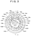
- Fig. 1 is a longitudinal sectional view of a reclining device 1 according to an embodiment of the invention, and corresponds to a section indicating line I-I shown in Fig. 3.
- Fig. 2 is an exploded perspective view of the reclining device 1.
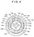
- Figs. 3 and 4 arc front views of the reclining device 1 removed of some of its components.
- the reclining device 1 is designed to constitute a vehicular reclining seat.
- the reclining device 1 is composed of a stationary disc 11, a movable disc 12, a support shaft 13, an operation lever 14, four slide pawls 15 (15A, 15B, 15C, 15D), a rotating cam 16, an operation arm 17, a working plate 18, an unlock plate 19, a spiral spring 21 and a set plate 22.
- the stationary disc 11 functions as a holder of the invention.
- the movable disc 12 includes a ratchet of the invention.
- the rotating cam 16 and the working plate 18 functions as a cam body of the invention.
- the slide pawl 15A corresponds to "at least one of the pawls" of the invention.
- a radially outside inner peripheral surface of a small-width hole portion 19c2, which will be described below, corresponds to an edge of the invention.
- a cam pin 15e and an unlock cam pin 15g which will also be described below, correspond to an engagement portion of the invention.
- the unlock plate 19 corresponds to an unlock member of the invention.
- the stationary disc 11 is mounted on the side of a seat cushion of a vehicular seat, whereas the movable disc 12 is mounted on the side of a seat back of the vehicular seat.
- the stationary disc 11 and the movable disc 12 are fitted facing each other.
- the stationary disc 11 and the movable disc 12 are integrated by bending a leading end of a tubular portion 22b of a set plate 22 fitted from the side of the movable disc 12 onto an outer peripheral edge of the stationary disc 11.
- the slide pawls 15, the rotating cam 16, the operation arm 17, the working plate 18, the unlock plate 19 and the spiral spring 21 are stored in a storage space portion formed by the stationary disc 11 and the movable disc 12.
- These components are supported by the support shaft 13 penetrating central portions thereof either directly or indirectly by other components.
- the operation lever 14 is attached to an outer end of the support shaft 13.
- the stationary disc 11 has a stepped circular recess 11b inside a disc body 11a.
- An assembly groove 11c that intersects in the shape of a crucifix and that extends both lengthwise and widthwise is formed in the circular recess 11b.
- the assembly groove I 1c is much deeper than the circular recess 11b.
- Four outer comer portions of an intersecting portion of the assembly groove 11c are receptive support wall portions 11d, which assume a generally triangular shape.
- the receptive support wall portions 1 1d are as thick as the disc body 11a.
- a through-hole 11e and catch grooves 11f are formed in a central portion of the circular recess 11b.
- the movable disc 12 has a stepped circular recess 12b inside a disc body 12a.
- Inner teeth are formed along the entire circumference of an inner periphery of an annular portion, which is a large-diameter portion outside the circular recess 12b.
- the annular portion is formed as a ratchet 12c.
- the disc body 12a is dimensioned such that it is tightly fitted into the circular recess 11b of the stationary disc 11 when superposed onto the side of an inner face of the stationary disc 11.
- a through-hole 12d facing the through-hole 11e of the stationary disc 11 is formed in a center of the circular recess 12b.
- four engaging protrusion portions 12e are arranged circumferentially at the center of the circular recess 12b at intervals of a certain distance.
- slide pawls 15 are essentially identical in configuration, the slide pawl 15A is different in its specific function from the other slide pawls 15B, 15C and 15D. Therefore, when referring to the specific function of the slide pawl 15A in the following description of the slide pawls 15 (15A, 15B, 15C, 15D), the slide pawl 15A will be referenced as distinct from the slide pawls 15B, 15C and 15D. Elsewhere, however, all the slide pawls 15A, 15B, 15C and 15D will be referenced generically as the slide pawl 15.
- the slide pawl 15 has at a top portion of a generally arcuate pawl body 15a (radially outside with the reclining device 1 assembled) a teeth portion 15b that can engage the ratchet 12c of the movable disc 12. Further, the slide pawl 15 has on the side opposite the top portion of the pawl body 15a (radially inside with the reclining device 1 assembled) a pair of right and left leg portions 15c, 15d.
- a cam pin 15e which is generally in the shape of a square pole and which protrudes toward the after-mentioned working plate 18 with the reclining device 1 assembled, is formed on the side opposite the top portion of the pawl body 15a at a position close to an end leg 15c.
- the cam pin 15e of the slide pawl 15A is slightly longer than cam pins 15e of the other slide pawls. Only the slide pawl 15A has the unlock cam pin 15g.
- the unlock cam pin 15g is also formed generally in the shape of a square pole.
- the unlock cam pin 15g is also formed on the side opposite the top portion of the pawl body 15a at a position close to the end leg 15d, in such a manner as to protrude toward the working plate 18.
- the unlock cam pin 15g is as long as the cam pin 15e of the slide pawl 15A.
- the rotating cam 16 is a generally circular plate. As shown in Figs. 2 to 4, the rotating cam 16 has at an outer peripheral edge of the cam body 16a four cam portions each of which is composed of receptive support cam portions 16b, 16c and 16d. The four cam portions are arranged circumferentially and equidistantly.
- a fitting hole 16e which is substantially identical in shape to the after-mentioned operation arm 17 and into which the operation arm 17 can be fitted, is formed in a central portion of the cam body 16a.
- Three engaging protrusion portions 16f are formed at intervals of a certain distance along a circumference stretching around a rotation center of the cam body 16a. The engaging protrusion portions 16f protrude toward the after-mentioned working plate 18 with the reclining device 1 assembled.
- the operation arm 17 has on a cylindrical body 17a an engaging arm portion 17b protruding outwardly.
- the operation arm 17 is substantially identical in shape to the fitting hole 16e of the rotating cam 16.
- the working plate 18 has a circular shape. As shown in Fig. 2, the working plate 18 has a circular through-hole 18b in a central portion of a plate body 18a. Three engaging holes 18c, which are arranged circumferentially at intervals of a certain distance, are formed in an inner peripheral edge of the through-hole 18b. Further, four cam grooves 18d1, 18d2, 18d3 and 18d4, which are arranged circumferentially at intervals of a certain distance, are formed in an outer peripheral side portion of the plate body 18a.
- the cam groove 18d1 has a generally arcuate shape. Further, the cam grooves 18d2, 18d3 and 18d4 are generally fan-shaped and identical in shape to one another.
- Part of an arc of the cam groove 18d1 is identical in shape to arcs of the cam grooves 18d2, 18d3 and 18d4. Each of the arcs extends gently from one end to the other end thereof approaching to a center.
- the cam groove 18d1 is located facing the unlock cam pin 15g and the cam pin 15e of the slide pawl 15A.
- the unlock plate 19 is a circular disc.
- a through-hole 19b is formed in a central portion of a plate body 19a.
- Four engaging holes 19d are formed circumferentially at the center of the plate body 19a.
- an arcuate long hole 19c is formed on the side of an outer peripheral edge of the unlock plate 19 in such a manner as to extend along the outer peripheral edge.
- the long hole 19c is composed of a large-width hole portion 19c1, a small-width hole portion 19c2 and a large-width hole portion 19c3.
- the large-width hole portions 19c1, 19c3 are equal in length and width.
- the small-width hole portion 19c2 is smaller in outer diameter than the large-width hole portions 19c1, 19c3.
- the long hole 19c is located facing the unlock cam pin 15g and the cam pin 15e of the slide pawl 15A.
- the spiral spring 21 has a predetermined number of turns. As shown in Fig. 2, an inner end 21a of the spiral spring 21 is wound rectangularly. An outer end 21b of the spiral spring 21 protrudes outwardly. The inner end 21a is so dimensioned as to be tightly fitted onto the cylindrical body 17a of the operation arm 17. The outer end 21b is so formed as to be caught in one of the catch grooves 11f of the stationary disc 11.
- the outer end 21b of the spiral spring 21 is caught in one of the catch grooves 11f of the stationary disc 11.
- the cylindrical body 17a of the operation arm 17 is inserted into the spiral spring 21 at the inner end 21a thereof.
- the rotating cam 16 is fitted onto the operation arm 17.
- An engaging arm 17b of the operation arm 17 is fitted in the fitting hole 16e of the rotating cam 16.
- the slide pawls 15 are radially slidably disposed in the assembly groove 11c of the stationary disc 11.
- the slide pawls 15 are prevented from moving circumferentially by the receptive support wall portions 11d.
- the slide pawls 15 are located on an outer periphery of the rotating cam 16 and arranged circumferentially at intervals of a certain distance.
- the working plate 18 is located facing the rotating cam 16 with the slide pawls 15 interposed therebetween.
- Each of the engaging protrusion portions 16f of the rotating cam 16 is in engagement with a corresponding one of the engaging holes 18c of the working plate 18.
- the working plate 18 is coupled with the rotating cam 16 and can rotate together therewith.
- the cam pin 15e of each of the slide pawls 15 is opposed to a corresponding one of the cam grooves 18d of the working plate 18.
- the cam pin 15e of each of the slide pawls 15 and the corresponding one of the cam grooves 18d of the working plate 18 constitute a cam mechanism that causes the slide pawl 15 to slide radially.
- the unlock plate 19 is located facing the slide pawls 15 with the working plate 18 interposed therebetween, and is located also in the circular recess 12b of the movable disc 12.
- the unlock plate 19 is coupled with the movable disc 12 such that they can rotate together circumferentially, with the engaging protrusion portions 12e of the movable disc 12 in engagement with the engaging holes 19d,
- the cam pin 15e and the unlock cam pin 15g of the slide pawl 15A are opposed to the long hole 19c of the unlock plate 19 by the cam groove 18d1 of the working plate 18.
- the cam pin 15e and the unlock cam pin 15g of the slide pawl 15A and the long hole 19c of the unlock plate 19 constitute a cam mechanism that causes the slide pawl 15A to slide radially.
- Figs. 3 and 4 are front views of the reclining device 1 removed of the stationary disc 11, the support shaft 13 and the spiral spring 21.
- Fig. 3 shows a state where the slide pawls 15 mesh with the ratchet 12c of the movable disc 12 so that a seat back S1 is locked with respect to a seat cushion S2.
- Fig. 4 shows a state where the slide pawls 15 have been retreated (moved away) from the ratchet 12c by turning the operation lever 14 so that the slide pawls 15 do not mesh with the ratchet 12c.
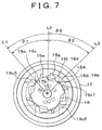
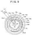
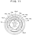
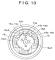
- Figs. 5, 7, 9, 11, 13 and 15 each show an operational relation among the movable disc 12, the ratchet 12c, the slide pawls 15 and the unlock plate 19 when the reclining device 1 is in operation.
- Figs. 5, 7, 9, 11, 13 and 15 are front views showing the reclining device 1 removed of components other than the movable disc 12, the ratchet 12c, the slide pawls 15 and the unlock plate 19.
- These drawings show the reclining device 1 that is installed to the left of a passenger when he or she is seated.
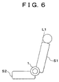
- Figs. 6, 8, 10, 12, 14 and 16 are side views of a reclining seat with its seat back in a tilt state corresponding to Figs. 5, 7, 9, 11, 13 and 15 respectively.
- each of the slide pawls 15 meshes with a portion of the ratchet 12c of the movable disc 12 which faces the corresponding one of the slide pawls 15.
- a spring force is applied to the rotating cam 16 by the spiral spring 21 by the operation arm 17 counterclockwise, so that the rotating cam 16 is held at such an angle that it abuts on the slide pawls 15.
- the seat back S1 stands upright at a foremost tilt position (initial-stage lock position) with respect to the seat cushion S2.
- the unlock cam pin 15g of the slide pawl 15A coupled with the unlock plate 19 is located in a stepped portion forming a border with the small-width hole portion 19c2 in the large-width hole portion 19c1 of the long hole 19c of the unlock plate 19.
- the operation lever 14 is rotated counterclockwise to unlock the seat back S1 from the seat cushion S2.
- the operation arm 17 rotates clockwise by the support shaft 13, so that the rotating cam 16 rotates clockwise by a predetermined amount.
- the receptive support cam portions 16b, 16c and 16d of the rotating cam 16 are brought out of abutment on the leg portions 15d, 15c and the inner surface portion 15f of each of the slide pawls 15 respectively.
- the rotating cam 16 stops holding the slide pawls 15.
- the rotating cam 16 makes the slide pawls 15 free to move radially inwardly, and the working plate 18 rotates together with the rotating cam 16.
- the working plate 18 radially inwardly presses the cam pins 15e of the slide pawls 15 by the outside inner peripheral surfaces of the cam grooves 18d, thus causing the cam pins 15e to slide.
- the working plate 18 brings the slide pawls 15 out of mesh with the ratchet 12c by retreating the slide pawls 15 from the ratchet 12c.
- Fig. 4 shows a state where the slide pawls 15 have retreated from the ratchet 12c and are out of mesh therewith.
- the movable disc 12 In the state where the slide pawls 15 are out of mesh with the ratchet 12c, the movable disc 12 can rotate with respect to the stationary disc 11 both clockwise and counterclockwise.
- the seat back S1 has been unlocked from the seat cushion S2. Therefore, the seat back S 1 can tilt with respect to the seat cushion S2.
- the seat back S1 can tilt backwards until it becomes substantially horizontal or can be folded forwards toward the seat cushion S2 until it becomes substantially horizontal.
- a base line L1 shown in Fig. 5 indicates an initial-stage lock position of the seat back S1.
- the seat back S1 shown in Fig. 6 is set substantially upright at the initial-stage lock position, i.e., along the base line L1.
- the operation lever 14 is turned to rotate the rotating cam 16 and the working plate 18 clockwise by a predetermined amount.
- the slide pawls 15 retreat from the ratchet 12c and are brought out of mesh therewith.
- the long hole 19c of the unlock plate 19 overlaps with the cam pin 15e and the unlock cam pin 15g of the slide pawl 15A.
- the ratchet 12c side of the cam pin 15e and the unlock cam pin 15g of the slide pawl 15A are made open by the large-width hole portions 19c1, 19c3, so that the cam pin 15e and the unlock cam pin 15g are allowed to move toward the ratchet 12c.
- the slide pawls 15 are allowed to move toward the ratchet 12c.
- the slide pawls 15 can move toward the ratchet 12c and come into mesh therewith. Further, these meshing states can be released by turning the operation lever 14. Accordingly, the seat back S 1 can be arbitrarily adjusted in tilt angle with respect to the seat cushion S2.
- a base line L3 shown in Fig. 7 indicates a final-stage lock position.
- the tilt angle of the seat back S1 can be adjusted within an angular range ⁇ 3, which is the sum of an angular range ⁇ 1 between the base lines L1, L2 and an angular range ⁇ 2 between the base lines L2, L3.
- Fig. 8 shows a state of movement of the reclining seat corresponding to the state shown in Fig. 7.
- a base line L4 shown in Fig. 9 indicates a rotational position of the seat back S1 when the small-width hole portion 19c2 of the unlock plate 19 overlaps with the unlock cam pin 15g of the slide pawl 15A. If the seat back S turns from the base line L1 to the base line L4 by an angle ⁇ 4, the small-width hole portion 19c2 of the unlock plate 19 moves from the initial-stage lock position to a position corresponding to the cam pin 15g of the slide pawl 15A.
- Fig. 12 is a side view showing a tilt state of the reclining seat shown in Fig. 11.
- the unlock plate 19 rotates to a position shown in Fig. 13. It is to be noted herein that the small-width hole portion 19c2 of the unlock plate 19 has deviated from the position corresponding to the unlock cam pin 15g of the slide pawl 15. However, since the cam pin 15e overlaps with the small-width hole portion 19c2 and thus is prevented from moving toward the ratchet 12c, the seat back S1 is held likewise free from the seat cushion S2.
- the movable disc 12 is free from the stationary disc 11.
- the seat back S1 can be folded forwards toward the seat cushion S2 until it becomes substantially horizontal.
- the small-width hole portion 19c2 deviates from the positions corresponding to the cam pin 15e and the unlock cam pin 15g of the slide pawl 15A as shown in Fig. 15.
- the large-width hole portion 19c3 overlaps with the cam pin 15e and the unlock cam pin 15g of the slide pawl 15A.
- the slide pawls 15 are allowed to move toward the ratchet 12c.
- the rotating cam 16 and the working plate 18 return while rotating counterclockwise. Then, the rotating cam 16 causes the slide pawls 15 to move toward the ratchet 12c and brings them into mesh with the ratchet 12c. Thus, the movable disc 12 is prevented from rotating with respect to the stationary disc 11, so that the seat back S1 is locked with respect to the seat cushion S2 while lying substantially horizontally.
- a base line L5 shown in Fig. 15 indicates a tilt position of the foremost folded seat back S1. If the seat back S1 turns from the base line L1 to the base line L5 by an angle ⁇ 5 (which includes the angle ⁇ 4), it is folded to become substantially horizontal.
- the operation lever 14 In order to return the seat back S1 that has been folded forwards to its upright position, the operation lever 14 is turned so that the slide pawls 15 assuming the meshing state shown in Fig. 15 retreat from the ratchet 12c and come out of mesh therewith. Then, the seat back S1 is tilted backwards by a predetermined amount. Turning operation of the operation lever 14 is then cancelled to turn the seat back S1 further backwards. Since the small-width hole portion 19c2 of the unlock plate 19 overlaps with the cam pin 15e of the slide pawl 15A, the movable disc 12 is free from the stationary disc 11 and allows the seat back S1 to tilt backwards. This state corresponds to Fig. 13. If the seat back S1 is tilted backwards, it assumes the state shown in Fig. 11, the state shown in Fig. 9, and finally the state shown in Fig. 6.
- the large-width hole portion 19c1 of the unlock plate 19 reaches the position corresponding to the unlock cam pin 15g of the slide pawl 15A. Because the ratchet 12c side of the slide pawl 15A is then made open, the slide pawl 15A is allowed to move toward the ratchet 12c. Then, as the slide pawl 15A moves toward the ratchet 12c, the slide pawls 15 are released from a state where they are spaced from the cam pins 15e.
- the rotating cam 16 returns while rotating counterclockwise, and the slide pawls 15 move toward the ratchet 12c and come into mesh therewith.
- the seat back S1 is released from a state where it is free from the seat cushion S2.
- the seat back S1 is locked with respect to the seat cushion S2 at the initial-stage lock position corresponding to the base line L1 and is held almost upright at a predetermined tilt angle.
- the reclining device 1 employs the unlock plate 19 to hold a specific one of the slide pawls 15, i.e., the slide pawl 15A in retreat in such a direction that the slide pawl 15A is brought out of mesh with the ratchet 12c. Then, the slide pawl 15A operates the working plate 18 and the rotating cam 16 so that all the slide pawls 15 are held in retreat in such a direction that they are brought out of mesh with the ratchet 12c. Thus, all the slide pawls 15 are brought out of mesh with the ratchet 12c.
- the unlock plate 19 holds only one of the slide pawls 15, i.e., the slide pawl 15A in retreat from the ratchet 12c, all the slide pawls 15 can be held out of mesh with the ratchet 12c, and free zones of the slide pawls 15 can be formed. These free zones can be set even if the angular range where the slide pawl 15A is brought out of mesh with the ratchet 12c and the angular range where the adjacent slide pawls 15B, 15D are to mesh with the ratchet 12c overlap with each other in a plan view.
- the reclining device 1 is designed to be attached to a hinge portion between the seat cushion S2 and the seat back S1 so as to constitute a vehicular reclining seat.
- the reclining device 1 is adapted for a vehicular reclining seat as will be mentioned below.
- the reclining device 1 is set such that a lock state is constituted, i.e., that the slide pawls 15 can mesh with the ratchet 12c (1) if the seat back S1 forms an angle larger than a predetermined angle with the seat cushion S2 (on the side from the base line L to the base lines L2, L3).
- the reclining device 1 is set such that a lock state is not constituted, i.e., that the slide pawls 15 cannot mesh with the ratchet 12c (2) if the seat back S1 forms an angle smaller than the predetermined angle with the seat cushion S2 (on the side from the base line L1 to the base lines L4, L5).
- the reclining device 1 is set such that a lock state is constituted, i.e., that the slide pawls 15 mesh with the ratchet 12c (3) if the seat back S1 forms a minimum angle with the seat cushion S2 (at the position corresponding to the base line L5).
- the vehicular reclining seat employing the reclining device 1 can constitute a lock state in a state where the seat back S1 has been folded down until it forms a minimum angle with the seat cushion S2, that is, until it reaches a turning position corresponding to the base line L5, i.e., becomes substantially horizontal.
- the seat back S1 can be prevented from vibrating unstably.
- the back portion of the seat back S1 can be utilized as a table.
- the reclining device 1 is able to set the angles to be set to bring a pawl into mesh and the angles to be set to bring the pawls out of mesh in large range. And the sum of the angles to be set to bring the pawls into mesh and the angles to be set to bring the pawls out of mesh exceeds 360°.
- the slide pawl 15A has two protrusion portions facing the long hole 19c of the unlock plate 19, i.e., the cam pin 15e and the unlock cam pin 15g, the small-width hole portion 19c2 of the unlock plate 19 can be reduced in length.
- the sufficiently long large-width hole portions 19c1, 19c3 can be formed at opposed ends of the small-width hole portion 19c2. Therefore, the same unlock plate 19 can be employed in the reclining device 1 on the other side by changing an angle for mounting the unlock plate 19 to the ratchet 12c.
- the unlock plate 19 can be integrated with the movable disc 12 equipped with the ratchet 12c in the turning direction. Therefore, the free zone of the reclining device 1, which differs depending on the type of vehicles, can be dealt with easily by a means for suitably changing the unlock plate 19.
- the reclining device 1 may employ a slide pawl that does not have any unlock cam pin. This construction can make the slide pawl easier.
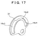
- the reclining device 1 can have a generally fan-shaped unlock plate 31 as shown in Fig. 17. If a hole 19c4 is substituted for a hole corresponding to the large-width hole portion 19c3 of the long hole 19c, size reduction of parts can be achieved.
- the unlock plate 31 is fan-shaped and thus can be mounted easily by engaging its opposed circular ends with a pair of right and left engaging protrusion portions formed along the peripheral edge of the circular recess 12b of the movable disc 12.
- the engaging protrusion portions of the movable disc 12 may have an arbitrary shape.
Landscapes
- Engineering & Computer Science (AREA)
- Aviation & Aerospace Engineering (AREA)
- Transportation (AREA)
- Mechanical Engineering (AREA)
- Chairs For Special Purposes, Such As Reclining Chairs (AREA)
- Seats For Vehicles (AREA)
Priority Applications (1)
| Application Number | Priority Date | Filing Date | Title |
|---|---|---|---|
| EP04076934A EP1462302A3 (fr) | 2000-10-13 | 2001-10-12 | Dispositif d'inclinaison d'un siège |
Applications Claiming Priority (2)
| Application Number | Priority Date | Filing Date | Title |
|---|---|---|---|
| JP2000313961 | 2000-10-13 | ||
| JP2000313961A JP3804431B2 (ja) | 2000-10-13 | 2000-10-13 | リクライニング装置 |
Related Child Applications (2)
| Application Number | Title | Priority Date | Filing Date |
|---|---|---|---|
| EP04076934A Division EP1462302A3 (fr) | 2000-10-13 | 2001-10-12 | Dispositif d'inclinaison d'un siège |
| EP04076934.1 Division-Into | 2004-07-05 |
Publications (4)
| Publication Number | Publication Date |
|---|---|
| EP1197377A2 true EP1197377A2 (fr) | 2002-04-17 |
| EP1197377A3 EP1197377A3 (fr) | 2003-12-03 |
| EP1197377B1 EP1197377B1 (fr) | 2005-12-28 |
| EP1197377B2 EP1197377B2 (fr) | 2009-07-01 |
Family
ID=18793291
Family Applications (2)
| Application Number | Title | Priority Date | Filing Date |
|---|---|---|---|
| EP01124530A Expired - Lifetime EP1197377B2 (fr) | 2000-10-13 | 2001-10-12 | Dispositif d'inclinaison d'un siège |
| EP04076934A Withdrawn EP1462302A3 (fr) | 2000-10-13 | 2001-10-12 | Dispositif d'inclinaison d'un siège |
Family Applications After (1)
| Application Number | Title | Priority Date | Filing Date |
|---|---|---|---|
| EP04076934A Withdrawn EP1462302A3 (fr) | 2000-10-13 | 2001-10-12 | Dispositif d'inclinaison d'un siège |
Country Status (4)
| Country | Link |
|---|---|
| US (1) | US6758525B2 (fr) |
| EP (2) | EP1197377B2 (fr) |
| JP (1) | JP3804431B2 (fr) |
| DE (1) | DE60116222T3 (fr) |
Cited By (8)
| Publication number | Priority date | Publication date | Assignee | Title |
|---|---|---|---|---|
| FR2857916A1 (fr) * | 2003-07-25 | 2005-01-28 | Faurecia Sieges Automobile | Systeme de freinage d'un premier element par rapport a un deuxieme element et siege de vehicule comprenant un tel systeme de freinage |
| FR2873634A1 (fr) * | 2004-07-29 | 2006-02-03 | Faurecia Sieges Automobile | Gamme de mecanisme d'articulation et siege comprenant un mecanisme de cette gamme |
| FR2882707A1 (fr) * | 2005-03-02 | 2006-09-08 | Faurecia Sieges Automobile | Siege de vehicule et procede de fabrication d'un tel siege |
| WO2007115601A1 (fr) * | 2006-04-04 | 2007-10-18 | Keiper Gmbh & Co. Kg | Ferrure pour un siege de vehicule |
| EP1781486A4 (fr) * | 2004-08-13 | 2009-06-17 | Km & I Co Ltd | Dispositif d' inclinaison pour vehicule |
| US7766429B2 (en) | 2005-09-26 | 2010-08-03 | Toyota Boshoku Kabushiki Kaisha | Rotation lock device |
| CN113085681A (zh) * | 2021-05-08 | 2021-07-09 | 恺博(常熟)座椅机械部件有限公司 | 一种大行程座椅扶手机构 |
| EP4197855A1 (fr) * | 2019-02-25 | 2023-06-21 | Brose Fahrzeugteile SE & Co. Kommanditgesellschaft, Coburg | Ferrure d'arrêt pour un siège de véhicule |
Families Citing this family (49)
| Publication number | Priority date | Publication date | Assignee | Title |
|---|---|---|---|---|
| DE10217873B4 (de) * | 2001-04-23 | 2008-08-14 | Aisin Seiki K.K., Kariya | Gelenkbeschlag |
| JP4834932B2 (ja) * | 2001-07-19 | 2011-12-14 | アイシン精機株式会社 | シートリクライニング装置 |
| JP3979132B2 (ja) * | 2002-03-13 | 2007-09-19 | トヨタ紡織株式会社 | リクライニング装置における摺動隙間の設定方法 |
| JP3934991B2 (ja) * | 2002-05-27 | 2007-06-20 | 日本テクニカ株式会社 | 車輌シートのリクライニング機構 |
| EP1552769B1 (fr) * | 2002-08-02 | 2009-06-24 | Toyota Boshoku Kabushiki Kaisha | Dispositif inclinable et procede de verrouillage dudit dispositif |
| JP4135141B2 (ja) * | 2002-11-27 | 2008-08-20 | テイ・エス テック株式会社 | 定点復帰機能付きリクライニング装置並びに同リクライニング装置を備える車両用シート |
| US6890034B2 (en) * | 2003-01-28 | 2005-05-10 | Fisher Dynamics Corporation | Compact recliner with locking cams |
| US6910738B2 (en) | 2003-01-28 | 2005-06-28 | Fisher Dynamics Corporation | Device and method for assembling a recliner mechanism |
| US20050168034A1 (en) * | 2004-01-21 | 2005-08-04 | Scott Fast | Disc recliner with dual cams |
| US7097253B2 (en) * | 2004-03-11 | 2006-08-29 | Fisher Dynamics Corporation | Round recliner assembly with rear folding latch |
| US7025422B2 (en) * | 2004-03-11 | 2006-04-11 | Fisher Dynamics Corporation | Round recliner assembly with rear folding latch |
| KR100458316B1 (ko) * | 2004-03-18 | 2004-11-26 | (주)엠알 | 자동차 시트용 리클라이닝 장치 |
| US7021715B2 (en) * | 2004-07-07 | 2006-04-04 | Delta Kogyo Co., Ltd. | Recliner adjuster for a seat |
| US8376464B2 (en) | 2004-08-13 | 2013-02-19 | Km & I Co., Ltd. | Vehicle recliner |
| CA2537924C (fr) * | 2005-03-03 | 2008-10-07 | Faurecia Automotive Seating Canada Limited | Mecanisme d'inclinaison rotatif pour siege de vehicule |
| JP4639927B2 (ja) * | 2005-04-26 | 2011-02-23 | トヨタ紡織株式会社 | 継手装置 |
| DE102005054490B4 (de) * | 2005-11-16 | 2008-08-21 | Keiper Gmbh & Co.Kg | Beschlag für einen Fahrzeugsitz |
| RU2486075C2 (ru) * | 2006-10-12 | 2013-06-27 | Джонсон Контролз Текнолоджи Компани | Поворотный механизм регулятора наклона спинки сиденья |
| WO2008086598A1 (fr) * | 2007-01-17 | 2008-07-24 | Intier Automotive Inc. | Ensemble d'inclinaison à disque à synchronisation sollicitée |
| JP5177144B2 (ja) * | 2007-08-08 | 2013-04-03 | トヨタ紡織株式会社 | 車両用シートの回転留め装置 |
| JP5050754B2 (ja) * | 2007-09-21 | 2012-10-17 | アイシン精機株式会社 | 車両用シートリクライニング装置 |
| JP2009072413A (ja) * | 2007-09-21 | 2009-04-09 | Aisin Seiki Co Ltd | 車両用シートリクライニング装置 |
| US7677666B2 (en) | 2008-01-09 | 2010-03-16 | Bae Industries, Inc. | Disc recliner assembly incorporated into a seatback/seat base pivot associated with a vehicle seat |
| CA2711966C (fr) * | 2008-01-17 | 2016-05-17 | Fisher Dynamics Corporation | Mecanisme de siege inclinable rond |
| JP5393990B2 (ja) * | 2008-04-01 | 2014-01-22 | デルタ工業株式会社 | シートのリクライニング装置 |
| JP5102705B2 (ja) * | 2008-06-13 | 2012-12-19 | 株式会社今仙電機製作所 | リクライニング装置 |
| JP5098867B2 (ja) * | 2008-07-15 | 2012-12-12 | アイシン精機株式会社 | シートリクライニング装置 |
| DE102009041492A1 (de) * | 2009-09-10 | 2011-03-24 | Keiper Gmbh & Co. Kg | Beschlag für einen Fahrzeugsitz |
| JP2012011165A (ja) * | 2010-05-31 | 2012-01-19 | Imasen Electric Ind Co Ltd | リクライニング装置 |
| WO2012103466A1 (fr) * | 2011-01-27 | 2012-08-02 | Johnson Controls Technology Company | Dispositif d'inclinaison à levier manuel |
| DE102011013163B4 (de) * | 2011-03-04 | 2014-05-15 | Keiper Gmbh & Co. Kg | Beschlag für einen Fahrzeugsitz |
| JP5434968B2 (ja) | 2011-06-13 | 2014-03-05 | アイシン精機株式会社 | 車両用シートリクライニング装置 |
| FR2977204B1 (fr) * | 2011-06-28 | 2016-09-30 | Faurecia Sieges D'automobile | Dispositif de reglage angulaire pour siege de vehicule |
| JP5969873B2 (ja) * | 2012-09-27 | 2016-08-17 | 富士機工株式会社 | 車両用シートリクライニング装置 |
| US9296315B2 (en) | 2013-02-26 | 2016-03-29 | Fisher & Company, Incorporated | Recliner mechanism with backdriving feature |
| US9902297B2 (en) | 2014-06-11 | 2018-02-27 | Fisher & Company, Incorporated | Latch mechanism with locking feature |
| JP6488746B2 (ja) * | 2015-02-10 | 2019-03-27 | アイシン精機株式会社 | 車両用シートリクライニング装置 |
| CN105691250A (zh) * | 2016-01-18 | 2016-06-22 | 江苏忠明祥和精工股份有限公司 | 汽车座椅调角器 |
| JP6682300B2 (ja) * | 2016-03-04 | 2020-04-15 | シロキ工業株式会社 | シートリクライニング装置 |
| KR20180026934A (ko) * | 2016-09-05 | 2018-03-14 | (주) 티엠지코리아 | 플로팅 플레이트, 플로팅 플레이트를 포함하는 기어박스 및 이를 포함하는 밸브 |
| JP2019147417A (ja) * | 2018-02-26 | 2019-09-05 | トヨタ紡織株式会社 | 乗物用シートリクライニング装置 |
| US11260777B2 (en) * | 2018-08-29 | 2022-03-01 | Fisher & Company, Incorporated | Recliner heart for seat recliner assembly |
| US11364577B2 (en) | 2019-02-11 | 2022-06-21 | Fisher & Company, Incorporated | Recliner mechanism for seat assembly and method of manufacturing |
| US11845367B2 (en) | 2019-04-18 | 2023-12-19 | Fisher & Company, Incorporated | Recliner heart having lubricant member |
| US11192473B2 (en) | 2019-08-30 | 2021-12-07 | Fisher & Company, Incorporated | Release handle for recliner mechanism of vehicle seat |
| US11607976B2 (en) | 2020-03-06 | 2023-03-21 | Fisher & Company, Incorporated | Recliner mechanism having bracket |
| US11766957B2 (en) | 2021-02-16 | 2023-09-26 | Fisher & Company, Incorporated | Release mechanism for seat recliner assembly |
| US11897372B2 (en) | 2021-05-06 | 2024-02-13 | Fisher & Company, Incorporated | Recliner heart having biasing members |
| US11850975B2 (en) | 2021-06-11 | 2023-12-26 | Fisher & Company, Incorporated | Vehicle seat recliner mechanism with welded spring |
Citations (1)
| Publication number | Priority date | Publication date | Assignee | Title |
|---|---|---|---|---|
| JPH06125821A (ja) | 1991-03-05 | 1994-05-10 | Bertrand Faure Automob Bfa | 背も垂れ部の調整装置 |
Family Cites Families (18)
| Publication number | Priority date | Publication date | Assignee | Title |
|---|---|---|---|---|
| US5161856A (en) | 1990-03-17 | 1992-11-10 | Tachi-S Co., Ltd. | Reclining device for a seat |
| FR2722739B1 (fr) † | 1994-07-22 | 1996-09-27 | Faure Bertrand Equipements Sa | Perfectionnements aux articulations pour sieges de vehicules |
| FR2740406B1 (fr) | 1995-10-27 | 1998-01-02 | Faure Bertrand Equipements Sa | Articulation pour siege de vehicule |
| JP3646422B2 (ja) * | 1996-08-29 | 2005-05-11 | アイシン精機株式会社 | シートリクライニング装置 |
| FR2747626B1 (fr) | 1997-04-30 | 1999-01-08 | Cesa | Articulation pour siege, et siege pour vehicule automobile muni de cette articulation |
| FR2766137B1 (fr) * | 1997-07-15 | 1999-10-01 | Faure Bertrand Equipements Sa | Siege de vehicule equipe d'un mecanisme d'articulation |
| FR2766138B1 (fr) | 1997-07-17 | 1999-10-01 | Faure Bertrand Equipements Sa | Mecanisme d'articulation pour siege de vehicule, et siege de vehicule equipe d'un tel mecanisme |
| JPH1156513A (ja) * | 1997-08-27 | 1999-03-02 | Ikeda Bussan Co Ltd | リクライニング装置 |
| JP3948086B2 (ja) * | 1997-12-02 | 2007-07-25 | アイシン精機株式会社 | シートリクライニング装置 |
| FR2777234B1 (fr) | 1998-04-09 | 2000-06-16 | Faure Bertrand Equipements Sa | Siege de vehicule equipe d'un mecanisme d'articulation, et mecanisme de memorisation pour un tel siege |
| FR2777837B1 (fr) † | 1998-04-27 | 2000-07-07 | Faure Bertrand Equipements Sa | Mecanisme d'articulation pour siege de vehicule, et siege de vehicule equipe d'un tel mecanisme |
| CA2338514C (fr) † | 1998-07-28 | 2007-09-11 | Magna Interior Systems Inc. | Mecanisme d'inclinaison |
| DE19904300C1 (de) † | 1999-01-28 | 2000-08-03 | Keiper Gmbh & Co | Rastbeschlag für einen Fahrzeugsitz |
| JP2000333756A (ja) * | 1999-05-28 | 2000-12-05 | Fuji Kiko Co Ltd | 車両用シートリクライニング装置 |
| JP4374657B2 (ja) * | 1999-06-08 | 2009-12-02 | アイシン精機株式会社 | シートリクライニング装置 |
| JP4142209B2 (ja) * | 1999-06-24 | 2008-09-03 | 日本発条株式会社 | 緊急ロック装置及びそれを用いた車両用リクライナ付きシート |
| JP2001017259A (ja) | 1999-07-09 | 2001-01-23 | Delta Kogyo Co Ltd | リクライナのアンロック保持構造 |
| JP4595256B2 (ja) | 2001-06-26 | 2010-12-08 | アイシン精機株式会社 | シートリクライニング装置 |
-
2000
- 2000-10-13 JP JP2000313961A patent/JP3804431B2/ja not_active Expired - Lifetime
-
2001
- 2001-10-12 US US09/974,864 patent/US6758525B2/en not_active Expired - Lifetime
- 2001-10-12 DE DE60116222T patent/DE60116222T3/de not_active Expired - Lifetime
- 2001-10-12 EP EP01124530A patent/EP1197377B2/fr not_active Expired - Lifetime
- 2001-10-12 EP EP04076934A patent/EP1462302A3/fr not_active Withdrawn
Patent Citations (1)
| Publication number | Priority date | Publication date | Assignee | Title |
|---|---|---|---|---|
| JPH06125821A (ja) | 1991-03-05 | 1994-05-10 | Bertrand Faure Automob Bfa | 背も垂れ部の調整装置 |
Cited By (11)
| Publication number | Priority date | Publication date | Assignee | Title |
|---|---|---|---|---|
| FR2857916A1 (fr) * | 2003-07-25 | 2005-01-28 | Faurecia Sieges Automobile | Systeme de freinage d'un premier element par rapport a un deuxieme element et siege de vehicule comprenant un tel systeme de freinage |
| FR2873634A1 (fr) * | 2004-07-29 | 2006-02-03 | Faurecia Sieges Automobile | Gamme de mecanisme d'articulation et siege comprenant un mecanisme de cette gamme |
| EP1781486A4 (fr) * | 2004-08-13 | 2009-06-17 | Km & I Co Ltd | Dispositif d' inclinaison pour vehicule |
| FR2882707A1 (fr) * | 2005-03-02 | 2006-09-08 | Faurecia Sieges Automobile | Siege de vehicule et procede de fabrication d'un tel siege |
| US7766429B2 (en) | 2005-09-26 | 2010-08-03 | Toyota Boshoku Kabushiki Kaisha | Rotation lock device |
| WO2007115601A1 (fr) * | 2006-04-04 | 2007-10-18 | Keiper Gmbh & Co. Kg | Ferrure pour un siege de vehicule |
| US7677667B2 (en) | 2006-04-04 | 2010-03-16 | Keiper Gmbh & Co. Kg | Fitting for a vehicle seat |
| EP4197855A1 (fr) * | 2019-02-25 | 2023-06-21 | Brose Fahrzeugteile SE & Co. Kommanditgesellschaft, Coburg | Ferrure d'arrêt pour un siège de véhicule |
| CN113085681A (zh) * | 2021-05-08 | 2021-07-09 | 恺博(常熟)座椅机械部件有限公司 | 一种大行程座椅扶手机构 |
| CN113085681B (zh) * | 2021-05-08 | 2022-04-05 | 恺博(常熟)座椅机械部件有限公司 | 一种大行程座椅扶手机构 |
| WO2022237662A1 (fr) * | 2021-05-08 | 2022-11-17 | 恺博(常熟)座椅机械部件有限公司 | Mécanisme d'accoudoir de siège à course longue |
Also Published As
| Publication number | Publication date |
|---|---|
| DE60116222T3 (de) | 2010-01-21 |
| EP1197377A3 (fr) | 2003-12-03 |
| JP2002119349A (ja) | 2002-04-23 |
| EP1197377B1 (fr) | 2005-12-28 |
| JP3804431B2 (ja) | 2006-08-02 |
| US6758525B2 (en) | 2004-07-06 |
| EP1462302A2 (fr) | 2004-09-29 |
| US20020043852A1 (en) | 2002-04-18 |
| EP1197377B2 (fr) | 2009-07-01 |
| DE60116222T2 (de) | 2006-08-17 |
| EP1462302A3 (fr) | 2009-03-04 |
| DE60116222D1 (de) | 2006-02-02 |
Similar Documents
| Publication | Publication Date | Title |
|---|---|---|
| EP1197377B1 (fr) | Dispositif d'inclinaison d'un siège | |
| US7097251B2 (en) | Reclining device for a seat | |
| US6722738B2 (en) | Reclining device for a seat | |
| EP1225086B1 (fr) | Dispositif d'inclinaison pour un siège | |
| CN100548742C (zh) | 用于车辆的座椅斜倚装置 | |
| US6520583B1 (en) | Compact disc recliner | |
| CN100366459C (zh) | 座椅倚靠机构 | |
| US7578557B2 (en) | Hinge mountings for a motor vehicle seat with at least two stopper arms | |
| EP1764258B1 (fr) | Dispositif d'inclinaison de siège | |
| JP3952900B2 (ja) | リクライニング装置 | |
| JP4497069B2 (ja) | 継手装置 | |
| JP6091766B2 (ja) | リクライニング装置 | |
| US6488338B1 (en) | Reclining mechanism for an automotive seat | |
| JP2004105637A (ja) | リクライニング装置 | |
| JP3762188B2 (ja) | リクライニング装置 | |
| JP2007082928A (ja) | 継手装置 | |
| JP5102705B2 (ja) | リクライニング装置 | |
| JPH08214978A (ja) | リクライニング装置 | |
| JPH04745Y2 (fr) | ||
| JP3616148B2 (ja) | リクライニング装置 | |
| JP3485962B2 (ja) | シートのリクライニング装置 | |
| JP3672965B2 (ja) | リクライニング装置 | |
| JPH08266360A (ja) | 両側ロック式のリクライニング装置 | |
| JPH0937880A (ja) | 内歯式リクライニングデバイス | |
| JP2006307889A (ja) | 継手装置 |
Legal Events
| Date | Code | Title | Description |
|---|---|---|---|
| PUAI | Public reference made under article 153(3) epc to a published international application that has entered the european phase |
Free format text: ORIGINAL CODE: 0009012 |
|
| 17P | Request for examination filed |
Effective date: 20011031 |
|
| AK | Designated contracting states |
Kind code of ref document: A2 Designated state(s): AT BE CH CY DE DK ES FI FR GB GR IE IT LI LU MC NL PT SE TR |
|
| AX | Request for extension of the european patent |
Free format text: AL;LT;LV;MK;RO;SI |
|
| PUAL | Search report despatched |
Free format text: ORIGINAL CODE: 0009013 |
|
| AK | Designated contracting states |
Kind code of ref document: A3 Designated state(s): AT BE CH CY DE DK ES FI FR GB GR IE IT LI LU MC NL PT SE TR |
|
| AX | Request for extension of the european patent |
Extension state: AL LT LV MK RO SI |
|
| RIC1 | Information provided on ipc code assigned before grant |
Ipc: 7B 60N 2/235 A Ipc: 7B 60N 2/20 B |
|
| 17Q | First examination report despatched |
Effective date: 20040401 |
|
| AKX | Designation fees paid |
Designated state(s): DE FR GB |
|
| GRAP | Despatch of communication of intention to grant a patent |
Free format text: ORIGINAL CODE: EPIDOSNIGR1 |
|
| GRAS | Grant fee paid |
Free format text: ORIGINAL CODE: EPIDOSNIGR3 |
|
| RAP1 | Party data changed (applicant data changed or rights of an application transferred) |
Owner name: TOYOTA BOSHOKU KABUSHIKI KAISHA |
|
| GRAA | (expected) grant |
Free format text: ORIGINAL CODE: 0009210 |
|
| AK | Designated contracting states |
Kind code of ref document: B1 Designated state(s): DE FR GB |
|
| REG | Reference to a national code |
Ref country code: GB Ref legal event code: FG4D |
|
| REF | Corresponds to: |
Ref document number: 60116222 Country of ref document: DE Date of ref document: 20060202 Kind code of ref document: P |
|
| ET | Fr: translation filed | ||
| PLBI | Opposition filed |
Free format text: ORIGINAL CODE: 0009260 |
|
| PLAX | Notice of opposition and request to file observation + time limit sent |
Free format text: ORIGINAL CODE: EPIDOSNOBS2 |
|
| 26 | Opposition filed |
Opponent name: KEIPER GMBH & CO. KG Effective date: 20060927 |
|
| PLBB | Reply of patent proprietor to notice(s) of opposition received |
Free format text: ORIGINAL CODE: EPIDOSNOBS3 |
|
| PUAH | Patent maintained in amended form |
Free format text: ORIGINAL CODE: 0009272 |
|
| STAA | Information on the status of an ep patent application or granted ep patent |
Free format text: STATUS: PATENT MAINTAINED AS AMENDED |
|
| 27A | Patent maintained in amended form |
Effective date: 20090701 |
|
| AK | Designated contracting states |
Kind code of ref document: B2 Designated state(s): DE FR GB |
|
| REG | Reference to a national code |
Ref country code: FR Ref legal event code: PLFP Year of fee payment: 16 |
|
| REG | Reference to a national code |
Ref country code: FR Ref legal event code: PLFP Year of fee payment: 17 |
|
| REG | Reference to a national code |
Ref country code: FR Ref legal event code: PLFP Year of fee payment: 18 |
|
| PGFP | Annual fee paid to national office [announced via postgrant information from national office to epo] |
Ref country code: GB Payment date: 20200930 Year of fee payment: 20 Ref country code: FR Payment date: 20200914 Year of fee payment: 20 |
|
| PGFP | Annual fee paid to national office [announced via postgrant information from national office to epo] |
Ref country code: DE Payment date: 20200929 Year of fee payment: 20 |
|
| REG | Reference to a national code |
Ref country code: DE Ref legal event code: R071 Ref document number: 60116222 Country of ref document: DE |
|
| REG | Reference to a national code |
Ref country code: GB Ref legal event code: PE20 Expiry date: 20211011 |
|
| PG25 | Lapsed in a contracting state [announced via postgrant information from national office to epo] |
Ref country code: GB Free format text: LAPSE BECAUSE OF EXPIRATION OF PROTECTION Effective date: 20211011 |