EP1178139A2 - Falschdrall-Texturiermaschine - Google Patents
Falschdrall-Texturiermaschine Download PDFInfo
- Publication number
- EP1178139A2 EP1178139A2 EP01124280A EP01124280A EP1178139A2 EP 1178139 A2 EP1178139 A2 EP 1178139A2 EP 01124280 A EP01124280 A EP 01124280A EP 01124280 A EP01124280 A EP 01124280A EP 1178139 A2 EP1178139 A2 EP 1178139A2
- Authority
- EP
- European Patent Office
- Prior art keywords
- thread
- false twist
- texturing machine
- machine according
- twist texturing
- Prior art date
- Legal status (The legal status is an assumption and is not a legal conclusion. Google has not performed a legal analysis and makes no representation as to the accuracy of the status listed.)
- Granted
Links
Images


Classifications
-
- D—TEXTILES; PAPER
- D02—YARNS; MECHANICAL FINISHING OF YARNS OR ROPES; WARPING OR BEAMING
- D02J—FINISHING OR DRESSING OF FILAMENTS, YARNS, THREADS, CORDS, ROPES OR THE LIKE
- D02J13/00—Heating or cooling the yarn, thread, cord, rope, or the like, not specific to any one of the processes provided for in this subclass
- D02J13/001—Heating or cooling the yarn, thread, cord, rope, or the like, not specific to any one of the processes provided for in this subclass in a tube or vessel
-
- B—PERFORMING OPERATIONS; TRANSPORTING
- B65—CONVEYING; PACKING; STORING; HANDLING THIN OR FILAMENTARY MATERIAL
- B65H—HANDLING THIN OR FILAMENTARY MATERIAL, e.g. SHEETS, WEBS, CABLES
- B65H51/00—Forwarding filamentary material
- B65H51/02—Rotary devices, e.g. with helical forwarding surfaces
- B65H51/04—Rollers, pulleys, capstans, or intermeshing rotary elements
- B65H51/06—Rollers, pulleys, capstans, or intermeshing rotary elements arranged to operate singly
-
- D—TEXTILES; PAPER
- D02—YARNS; MECHANICAL FINISHING OF YARNS OR ROPES; WARPING OR BEAMING
- D02G—CRIMPING OR CURLING FIBRES, FILAMENTS, THREADS, OR YARNS; YARNS OR THREADS
- D02G1/00—Producing crimped or curled fibres, filaments, yarns, or threads, giving them latent characteristics
- D02G1/02—Producing crimped or curled fibres, filaments, yarns, or threads, giving them latent characteristics by twisting, fixing the twist and backtwisting, i.e. by imparting false twist
- D02G1/0206—Producing crimped or curled fibres, filaments, yarns, or threads, giving them latent characteristics by twisting, fixing the twist and backtwisting, i.e. by imparting false twist by false-twisting
- D02G1/0266—Producing crimped or curled fibres, filaments, yarns, or threads, giving them latent characteristics by twisting, fixing the twist and backtwisting, i.e. by imparting false twist by false-twisting false-twisting machines
-
- D—TEXTILES; PAPER
- D02—YARNS; MECHANICAL FINISHING OF YARNS OR ROPES; WARPING OR BEAMING
- D02G—CRIMPING OR CURLING FIBRES, FILAMENTS, THREADS, OR YARNS; YARNS OR THREADS
- D02G1/00—Producing crimped or curled fibres, filaments, yarns, or threads, giving them latent characteristics
- D02G1/02—Producing crimped or curled fibres, filaments, yarns, or threads, giving them latent characteristics by twisting, fixing the twist and backtwisting, i.e. by imparting false twist
- D02G1/04—Devices for imparting false twist
- D02G1/08—Rollers or other friction causing elements
- D02G1/082—Rollers or other friction causing elements with the periphery of at least one disc
-
- B—PERFORMING OPERATIONS; TRANSPORTING
- B65—CONVEYING; PACKING; STORING; HANDLING THIN OR FILAMENTARY MATERIAL
- B65H—HANDLING THIN OR FILAMENTARY MATERIAL, e.g. SHEETS, WEBS, CABLES
- B65H2701/00—Handled material; Storage means
- B65H2701/30—Handled filamentary material
- B65H2701/31—Textiles threads or artificial strands of filaments
Definitions
- the invention relates to a false twist texturing machine for texturing synthetic Threads according to the preamble of claim 1.
- False twist texturing machines of this type have a large number of processing points - usually up to 216 processing points - on the long side of the machine are arranged side by side.
- each of the processing points a first delivery plant and a second delivery plant.
- the first delivery plant pulls the Thread from a supply spool and feeds it into a false twist zone.
- the second The delivery unit pulls the thread out of the false twist zone and conveys it to a winding device, where the thread speed and the stretching of the thread determined by the speed ratio between the second and first delivery unit is.
- a false twist texturing machine is known from EP 0 638 675, which one Swirl stop device designed as a rotatable conveyor roller within the false twist zone having. This does indeed mean that the swirl stop device the frictional force exerted on the thread only leads to a slight change in the thread tension, however, the absolute value of the thread tension in the false twist zone is essentially of the stretching ratio set between the first and second supply unit dependent. This would be a change in the thread tension in the false twist zone can only be achieved by changing the thread speed.
- the false twist texturing machine according to the invention and the inventive Process for texturing is particularly characterized in that the thread tension within the false twist zone regardless of that between the fume cupboard as well as the delivery plant downstream of the false twist zone Stretch ratio is changeable.
- the false twist generated in the thread runs as far back as is necessary to produce the crimp in the thread. Consequently the swirl stop device is arranged directly in front of the heating device.
- the Thread tension in the thread is determined by the frictional relationships between the running Thread and the peripheral surface of the driven conveyor roller affected.
- the supporting role can be driven such that the peripheral speed of the Conveyor roll is less than the thread speed.
- the thread would be with a sliding friction component guided over the circumferential surface of the conveyor roller. This leads to an increase in the thread tension in the false twist zone.
- the twist stop device In order to be able to absorb the twist moment of the thread, the twist stop device must a corresponding counter moment can be generated. This will be special advantageously achieved in that the thread in the looping area of the conveyor roller is guided in a zigzag shape on the peripheral surface of the conveyor roller. This creates there is friction at each deflection point between the thread and the conveyor roller, which essentially only counteracts the transverse forces of the thread.
- the zigzag thread track on the circumferential surface of the conveyor roller leaves it is particularly advantageous for individual ones arranged on the circumference of the conveyor roller Realize thread guide elements. This makes it possible to use any shape To realize thread deflection transverse to the thread running direction. The maximum deflection the thread is covered by opposite guide edges certainly. The number of deflections is determined by the distance between the Thread guide elements determined to each other.
- the thread guides are designed as rings, the driven conveyor roller bearing on both end faces is pushed onto it are. You can form the thread track between them or shaped like this be that the thread track by appropriate, radial from the inner ring surfaces outgoing, side extensions are formed.
- the conveyor roller is made of two Discs formed, the thread guide elements protruding laterally on their outer edges have and so arranged to each other on a drive shaft are that there is a zigzag thread track on one through the thread guide elements formed circumferential surface results.
- the thread guide elements are adjustable. This means that even with a small loop a high frictional torque on the circumferential surface of the conveyor roller in the thread be generated to absorb the twist moment of the thread.
- the thread can be attached to the conveyor roller by a movable thread deflection device be put on particularly gently, immediately in front of or behind the thread the conveyor roller is arranged such that the wrap angle on the conveyor roller is changeable by the deflection device.
- the wrap angle can be set on the conveyor roller in the range between 0 and 360 degrees.
- the thread is preferably first wrapped around the thread with very little Funding role created. Then can by the movement of the thread deflecting device the wrapping on the conveyor roller is continuously increased until the conveyor required wrapping or the wrapping required for the thread running is set.
- the thread guide edges of the thread guide elements have a radius of curvature of at least 1.5 mm. In order to is a thread-saving deflection for realizing the zigzag-shaped thread run guaranteed.
- the zigzag described by the thread track should be one after the other or other face of the conveyor roller open angle of at least 100 ° C. include.
- peripheral surface of the conveyor roller by thread guide elements can be achieved with a constant drive speed of the conveyor roller, that the peripheral speed of the peripheral surface is changeable. Likewise can thus the wrap angle on the peripheral surface of the conveyor roller in a small amount Dimensions are affected.
- the dimensions of the swirl stop roller according to the invention can be a relatively large one Range vary. To be able to absorb the twist moment of the thread However, it has been shown that a diameter of the peripheral surface of the conveyor roller of must be observed at least 40 mm.
- the thread running track i.e. the one with the thread Contacted areas of the conveyor roller and the deflection points on the thread guide elements to be provided with a low-wear coating or the Thread guides made of a suitable low-abrasion material, for example ceramic material manufacture.
- the twist of the threads can also be adequately braked by means of a godet.
- the godet has a leading edge to the To be able to absorb the shear force of the thread.
- Texturing machine is designed with a control device with a Thread tension sensor and is connected to the drive of the conveyor roller. Consequently the drive can be used directly depending on the measured thread tension control the conveyor roller. Is the control device a target value of the thread tension specified, the thread tension in the thread can be permanent by means of the conveyor roller be settled.
- the thread from a supply spool by means of the conveyor roller is deducted directly.
- the thread speed determined by the conveyor roller and the downstream delivery plant is determined by the thread speed of the conveyor roller and the downstream delivery plant.
- the conveyor roller is advantageously driven by an electric motor. This means that each processing point is independent of the neighboring processing points adjustable. This means that there can be one in each processing point the same high thread quality can be generated.
- the conveyor rollers are connected to each other by a continuous drive shaft is driven by a motor.
- the yarns at the delivery plants can be broken occurring winder formation either only by switching off the entire Machine or extremely difficult to remove with the drive shafts running. Furthermore, when creating a thread in a processing point the problem that the thread must be applied to supplying plants, the have a high conveying speed required for processing.
- the particularly preferred development of the invention according to claim 1 creates a false twist texturing machine, which is characterized in that the first delivery plant is formed by a conveyor roller.
- the required transport speed transferred to the thread by frictional forces.
- the thread wraps around for this the conveyor roller partially in the circumferential direction, with the thread transversely is deflected back and forth to its direction of travel, so that there is a zigzag Sets the thread running track on the circumference of the conveyor roller.
- the frictional forces on the thread are increased so far that the sliding of the thread on the peripheral surface is prevented.
- the zigzag-shaped thread running track means that only a tensioned thread on the Circumferential surface of the conveyor roller sets because of the sliding resistance at the deflection point the thread track must be overcome. If there is a broken thread, therefore do not form a tight wrap on the peripheral surface of the conveyor roller. The string will wind up on the circumference outside the thread track and can therefore easily be removed.
- the conveyor rollers can each be driven independently of one another, so that each processing point can be controlled individually. This can be particularly advantageous the so-called sympathy thread breaks can be avoided.
- a sympathy thread break is present if the thread break occurs at a processing point or has further thread breaks in adjacent processing points. With the invention Texturing machine is thus a high level of process reliability as well minimal thread scrap reached.
- the conveyor rollers can be coupled and / or releasably connected to the respective drives. So with one Winder formation the conveyor roller in a simple manner from the processing point remove and replace with a new conveyor roller. This will shorten it downtime significantly.
- the drives of the conveyor rollers are preferably designed as electric motors can be controlled by individual inverters or group inverters.
- the conveyor rollers are each by a Drive unit combined with an eddy current brake.
- Texturing machine is the conveyor roller by means of an application device operable.
- the conveyor rollers can be placed in the machine at locations that can only be reached by the operator with auxiliary devices.
- Another advantage is given in that the thread is guided with as few deflections as possible can, so that gentle thread treatment with few friction points is possible becomes.
- a false twist texturing machine is known from EP 0 641 877 A2, which consists of a Winding frame, a process frame and a gate frame composed is. An operating aisle is formed between the winding frame and the process frame, free from hand to the delivery plants and other treatment facilities to apply. This structure leads to a complicated thread run with several deflection points in the thread path between the creel and the Process frame.
- the particularly advantageous embodiment of the invention according to claim 6 or 7 provides a false twist texturing machine, which is immediately in front of the entrance of the first heater, the first delivery plant and which the heater and cooling device arranged in one plane.
- the arrangement ensures that the Thread during the passage of the heater and the cooling rail with very little friction is exposed. Using the delivery plant, the fadem is given a defined transport speed granted.
- the arrangement according to the invention could also the use of an additional swirl stop device in front of the heater can be dispensed with.
- the thread twist created in the thread run behind the cooling rail by the false twister would only progress to the first supplier. In the delivery plant then due to a friction torque or clamping generated by wrapping a dissolution of the twist on the thread.
- the swirl stop roller thus limits the False twist zone.
- the false twist texturing machine according to the invention stands out in particular due to a low overall height, since the level in which the Heater and cooling device are arranged horizontally or with a slight Inclination to the horizontal runs.
- the first delivery plant is operated with an application device. This ensures that the thread is safe by an operator at the start of the process can be created or can be removed if winder formation. It is particularly advantageous here if the application device is separated from the operating aisle to use here. This ensures that the creation occurs at the start of the process of the thread in the delivery plants as well as the individual treatment facilities can be carried out by an operator by hand.
- the application device can also consist of two sections, in which first section the application device is vertically movable, for example the thread from the operating position to a working height required for feeding bring. In the second section, the application device can be moved horizontally, so that, for example, the thread in a deflection roller arranged above the creel can be inserted and then the thread to the conveyor roller becomes.
- An advantageous development of the false twist texturing machine according to claim 9 has the advantage that the operating aisle and the doffing gear for clearing the texturing yarn bobbins are separate from each other. This ensures that the finished Coils can be cleared from a skimmer at any time without this Operating personnel are disturbed by this.
- the thread is also directly from the frame led directly to the heater entrance. This is the thread advantageously only guided over a deflection roller.
- a particularly advantageous embodiment according to claim 11 provides that the first delivery plant with a height-adjustable feed arm of the feed device is firmly connected.
- the first delivery plant can thus be located between an operating position and adjust an operating position back and forth. In the operating position, the can be reached by the operator, the thread is sent manually to the first delivery plant created. Then the delivery plant is moved through the feed arm into that for the texturing operation brought required operating position.
- the conveyor roller is fixed with a height-adjustable feed arm the application device and is connected by means of the height-adjustable application arm adjusted between an operating position and an operating position.
- a particularly preferred development of the invention according to claim 16 leads to a high flexibility of the respective processing point. This enables the delivery plants a processing point can be set individually. You can also even if the thread breaks in front of the winding device, the winder from the delivery plant can be easily removed.
- the drives of the conveyor rollers are interconnected via a control device connected so that the conveyor speeds of the supplying plants of a processing point set to the speed ratio required to draw the thread remains. This also allows any speed ratio between the Realize supplying plants.
- control device is connected to a thread tension sensor, which is located within the false twist zone.
- a thread tension sensor which is located within the false twist zone. This allows the for influence the process required thread tension by means of the conveyor rollers. This is particularly advantageous if after a long period of operation due to wear and tear the thread tension required for the process on the thread-guiding parts has risen to an impermissible level. You can also use this especially processes with a very low level of thread tension. at a thread break can also be an advantageous shutdown of the conveyor roller respectively.
- a further development of the invention provides that the control devices of a processing point is connected to a machine control unit. So that exists Possibility of a collective change initiated via the machine control unit the speed of the delivery plants. This arrangement is advantageous if, for example, the thread speed is increased in the processing point shall be. For this purpose, a collective adjustment is made with the machine control the processing point.
- the machine control of the controller specifies a time function. The time function controls the switching of the speeds of the supplying plants in such a way that no impermissible thread tension peaks occur.
- control device a processing point connected to an energy buffer, which at Power failure a controlled braking of the drives within the processing point allows. This can prevent the event of a power failure an uncontrolled termination of the process that causes a thread break.
- the thread guide on the conveyor roller can be designed such that the wrap angle greater than 180 ° can be realized on the conveyor roller without there is a substantial increase in thread tension in the thread.
- the thread can be deflect as far as possible thread tension neutral by such conveyor rollers. This is This is particularly advantageous for realizing compact machine structures. Leave it machine components can be combined into individual modules.
- a particularly advantageous development of the invention is after the second delivery plant with a second heater and a third designed as a conveyor roller Delivering plant executed.
- the heat treatment of the Thread takes place in the second heater, with the thread pulling force of the Speed ratio of the conveyor rollers in front and behind the heater depends.
- the set heater is arranged behind the second delivery plant in the process frame.
- a third delivery unit which conveys the thread for winding, is on the winding frame arranged.
- Another preferred embodiment of the false twist texturing machine has Individual drives for each unit in a processing point. So that becomes a high flexibility with regard to yarn processing and machine arrangement reached.
- the traversing and the friction roller are each via individual drives, preferably converter-controlled electric motors, driven.
- the false twister is also equipped with an electric single drive.
- the embodiment is in which the drive of the friction roller is axially integrated in the friction roller is special advantageous. This enables a particularly compact take-up unit to be created.
- the thread is fed with a thread before it is taken up
- Such projection devices are preferred as Roller preparation devices executed.
- the projection means is out a bath by means of a roller on the thread.
- To the flexibility of the processing point It is particularly advantageous to increase this roller by means of a roller motor is driven.
- the roller motor is independent of the neighboring Machining point driven.
- the thread is running A thread brake is arranged in front of the conveyor roller.
- the thread brake can be adjust so that a defined preload force is generated.
- the thread brake can be advantageous here by several thread guides partially wrapped around the thread realize, wherein one of the thread guides is adjustable to the wrap to change.
- the false twist texturing machine according to the invention is particularly distinguished due to the high flexibility in the production of textured yarn.
- Switching the supplying plants from the mooring speed to the operating speed is advantageously carried out according to a predetermined time function.
- a collective adjustment of the delivery plants can be carried out.
- it will strived to specify the time function for controlling the delivery plants in such a way that that was defined by the speed difference of neighboring supply plants
- the stretching ratio is only set when the operating speed is reached. Consequently become impermissible thread tension peaks when starting the machine after the thread is inserted in each unit avoided.
- the false twist texturing machine according to the invention is also preferred as one Double machine executed.
- the two machine halves become one another asked that the process racks are directly opposite each other.
- the electrical drive components for the false twist as well for the second delivery plant combined in a common drive cabinet can be.
- the machine according to the invention enables texturing that is particularly gentle on the thread at high texturing speeds. Because of the between the gate frame and the process frame is essentially a straight line of the thread, the thread spanning the take-up frame, a low height of the Machine realized. Despite this low overall height, the false twist texturing machine is equipped with a heating and cooling section, which is also suitable for high speeds of coarse polyester yarns.
- Each processing point has a supply spool 7 on which a thermoplastic Thread 4 is wound.
- the thread 4 is under a head thread guide 12 a certain voltage deducted by the first delivery mechanism 13.
- the thread 4 is then through a deflection roller 11 to the twist stop device 65 deflected and passes through an elongated heating device 18.
- the heater is a high temperature heater at which the heating surface temperature is above 300 ° C.
- EP 0 412 429 (Bag. 1720). in this respect reference is made to this publication.
- a cooling device 19 is located behind the heating device 18.
- the cooling device 19 is designed as an elongated cooling rail. Between the heater 18 and the cooling device 19, the thread is via a deflection roller 11 passed so that the heater 18 and the cooling device 19 V-shaped to each other are arranged.
- the texturing machine according to the invention is not limited to such a machine Arrangement, but also allows any other association between the heater and the cooling device, for example around a straight thread run realize as described later.
- This false twister 20 can be designed as a friction disk unit, as described for example in EP 0 744 480 (Bag. 2322).
- a second further delivery mechanism 21 is used to the thread 4 both via the heating device 18 and the cooling device 19 pull.
- This set heater 22 can be designed as a curved heating tube, which is surrounded by a heating jacket, with the heating tube from the outside Steam is heated to a certain temperature.
- the set heater 22 could, however also executed as the first heating device 18 as a high-temperature heater his.
- the thread 4 is in this case by means of a further third delivery mechanism 23 from the set heater pulled and conveyed to a winding device 9.
- the thread 4 is placed on a take-up spool 25, which is held by a friction roller 24 is driven, wound up.
- the supply plants 13, 21 and 23 are separate and in accordance with the process requirements with different, in a fixed relationship with each other Conveyor speeds driven.
- This drive can in a known manner Help through continuous drive shafts, the drive shafts then three supplier groups 13, 21 and 23 with each other - for example by one Change gear - are firmly coupled.
- the swirl stop devices 65 each designed as a conveyor roller 30, which are partially wrapped by the thread 4.
- the Thread 4 is in a zigzag-shaped thread running track on the peripheral surface the conveyor roller 30 guided - as described in more detail later.
- the conveyor roller 30 is coupled to a drive 46.
- the drive 46 of the swirl stop roller 30 is included connected to a control device 49. Between the swirl stop roller 30 and the heating device 18 a thread tension sensor 63 is arranged in the thread path. The thread tension sensor 63 is connected to the control device 49.
- Embodiment is the thread 4 with the delivery mechanism 13 from the supply spool 7 deducted and conveyed into the false twist zone. The false twist will the thread 4 introduced by the false twist unit 20. The false twist generated in this way runs back to the twist stop roller 30 in the opposite direction the thread in the false twist state by the heater 18 and Cooling device 19 out.
- the thread is twisted in the heating device 18 stretched and fixed, resulting in a strong impression of the swirl and thus leads to a good crimp result in the thread.
- Using the thread tension sensor 63 is the thread tension immediately before the entrance to the heating device 18 measured. This measured value is given to the control device 49, which at Determining a deviation between a target value the drive motor 46 Twist stop roller controls accordingly, so that the desired thread tension established. With this arrangement, processes can be run that are extremely lower thread tension.
- the thread is by means of the second delivery unit 21 pulled out of the false twist zone and then into a post-treatment zone e.g. led to the set heater 22 for shrinkage treatment of the thread.
- the embodiment of the texturing machine according to the invention from FIG. 2 represents compared to the embodiment of FIG. 1, another possibility of thread tension measurement in the false twist zone.
- the thread tension sensor 63 placed between the heater device 18 and the cooling device 19. This variant is particularly advantageous if a predetermined one is used to cool the thread Thread tension should be adjusted.
- twist stop device acts as the first delivery mechanism 13.
- the thread speed in the false twist zone is due to the conveyor speed of the conveyor roller 30 and the second delivery unit 21 set.
- a certain initial force to generate the frictional forces on the conveyor roller 30, could a thread brake between the head thread guide 12 and the conveyor roller 30 50 may be arranged.
- This embodiment is characterized by a special simple structure and procedure.
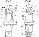
- the Swirl stop device consists of a conveyor roller 30 which has a circumference has zigzag-shaped thread running track 31.
- the zigzag-shaped thread track 31 is formed in that several on the peripheral surface 36 of the conveyor roller Thread guides 37 and 38 alternately in the circumferential direction at regular intervals are placed against each other (see Fig. 5).
- the thread guides 37 are with their Guide edges 39 assigned to the end face 40 of the conveyor roller 15.
- the thread guide 38 are assigned with their guide edges 45 to the opposite end face 41.
- the leading edges 39 and 45 of adjacent thread guides are offset from the central plane 43 aligned overlapping so that a thread that the guide edges 39th and 45 wraps around a zigzag thread run on the circumference of the conveyor roller 15 occupies.
- the guide edges 39 and 45 are the adjacent thread guide formed such that a notch 44 is formed in that the incoming thread 4 is caught and on the respective guide edges 39 or 45 can slide onto the peripheral surface 36. Due to the multiple wrapping on the thread guides 37 and 38, a frictional force is thus generated Takes up twist moment of the thread.
- the conveyor roller 30 is with a drive shaft 29 firmly coupled, which is driven by a drive (not shown here).
- the Thread tension in the thread is caused by the sliding or static friction between the thread 4 and the peripheral surface 36 and by the sliding or static friction between the thread 4 and the thread guide elements 37 and 38 influenced.
- the wrap angle can be used to influence the thread tension predetermined between the thread inlet and the thread outlet on the conveyor roller 30 become.
- the thread guide elements 37 and 38 are preferably made of ceramic Materials.
- the conveyor roller is attached to the end of a drive shaft 42.
- Conveyor roller 30 fixed to the drive shaft via a positive plug connection 42 coupled.
- the plug connection between the conveyor roller 30 and the drive shaft 42 is secured by means of a locking ring 47. This can be replaced perform the conveyor roller 30 with little effort.
- thread guide elements 37 alternately and 38 to perform unevenly, so that, for example, the wrap in Sub-areas of the conveyor roller by two successively arranged guide elements one disc per guide element is halved.
- the design of the conveyor rollers 30 is such that the thread tensile forces in a Process stage must be applied, transferred safely and a slip between thread 4 and conveyor roller 30 is avoided in order from processing point Processing point same delivery conditions as a prerequisite for a good product result to accomplish.
- This is achieved in particular in that the Thread running track 31 runs on a geometrically clearly defined diameter and thereby precisely reproducible speed from supplying plant to supplying plant and draw ratios are present.
- the parameters can be the Roll diameter, the number and thus the division of the thread guides on the Roll circumference, the roll width and also by the material selected Guide surfaces and by the arrangement of the conveyor rollers in the thread path of the The wrap angle between thread inlet and thread outlet can be changed.
- the thread delivery speeds can be adjusted and the thread input tensions individually at each processing point to adjust.
- This setting option is particularly useful at the start of the process for thread application is an advantage, in order to increase thread tension peaks in the thread avoid.
- FIG. Another example of a swirl stop roller is shown in FIG.
- the Swirl stop roller attached to a drive shaft 71 coaxially to one another Discs 72 and 73 formed.
- the discs have on the facing each other Pages on the outer edge of the thread guide elements 37 and 38.
- the thread guide elements 37 each have a leading edge 39 which extends in a circumferential direction extending guide surface 69 ends.
- the offset opposite Thread guide elements 38 have the thread guide edges 45, which are also shown in FIG of a circumferentially extending guide surface 75.
- the guide surfaces 69 and 75 are on one diameter and thus form one circumferential contact surface for the thread.
- the thread guide elements 37 are over a guide 28 is coupled to the disk 72.
- the thread guide elements 38 are also coupled to the disk 73 via a guide 74.
- the thread guide elements Through radial adjustment the thread guide elements, it is thus possible to change the diameter of the to change the guide surfaces 69 and 75 formed contact surface of the thread. Furthermore, the disks 72 and 73 are displaceable relative to one another, so that the Cover thread guide edges 39 and 45 more or less. This will an increase in the thread wrap on the thread guide elements 37 and 38 reached. In addition to the variable speed of rotation, there are thus further parameters available for the twist stop device to the thread tension of the thread to influence.
- FIG. A further exemplary embodiment of a swirl stop roller is shown in FIG. in this connection the thread guide elements 37 are connected to one another by a circumferential ring.
- the thread guide elements 38 are also via a circumferential ring coupled with each other.
- the two annular thread guide elements are here with the projecting guide edges 39 and 45 offset from one another in such a way that they interlock. This creates a notch 44 in which a incoming thread is introduced. Due to the deflection by means of the guide edges 39 and 45 the thread is then forced into a zigzag thread track.
- the thread lies on the circumferential guide surface 69.
- the wrap of the thread on the guide edges 39 and 45 can here by axial
- the thread guide elements 38 are displaced by an adjusting device 68.
- the thread guide elements 38 are here via a guide 67 with the conveyor roller 30 connected.
- the conveyor roller 30 is in turn on a drive shaft 71 attached.
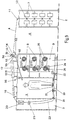
- the false twist texturing machine consists of a frame 2, a process frame 3 and a winding frame 1. Between the process frame 3 and the winding frame 1, an operating aisle 5 is formed. On the opposite side of the aisle 5 Side of the winding frame 1 is the gate frame 2 at a distance from the winding frame 1 arranged. Between the winding frame 1 and the gate frame 2 is thus a doffgang 6 is formed.
- Each processing point has a supply spool 7 on which a thermoplastic Thread 4 is wound.
- the thread 4 is a head thread guide 12 and a Deflection roller 11 or a thread guide under a certain tension by the first delivery plant 13 deducted.
- the thread In the embodiment according to Figures 9 and 10 is the thread between the creel 2 and the first delivery mechanism 13 without Pipe routing.
- pipe guides can also be used in this case Purpose of transporting the thread from the supply spool to the operating aisle become.
- a thread cutter 14 is arranged in the thread path in front of the first delivery mechanism 13. The thread can be cut by the thread cutter 14 if in the course of the process Faults occur between the first delivery unit 13 and the winding.
- the first delivery plant is designed here as a conveyor roller 30, which on its Has a zigzag-shaped thread running groove 31, as follows in the Description of Figures 3 to 6 is described.
- the conveyor roller 30 at the same time used as a twist stop to the false twist 20 in the thread stop swirl generated.
- Each processing point is a conveyor roller 30 assigned.
- the conveyor roller 30 is by means of an individual electric drive (here not shown) driven.
- the conveyor roller 30 and the drive are on a bracket 15 connected to a feed arm 16. This is also on the feed arm a thread cutter 14 arranged in the thread path in front of the conveyor roller 30 is fastened.
- the feed arm 16 is connected to a carriage 32.
- the carriage 32 will by a linear drive along the guide 33 between a - as shown in Fig. 9 - Operating position 34 and an operating position 35 moves.
- the thread is manually applied to the conveyor roller 30 by an operator become.
- the conveyor roller 30 is then moved by means of the application device 17 move to their operating position 34.
- the drive for example drives a group of conveyor rollers
- the conveyor rollers would then be coupled to the in their respective operating position Drive.
- the first delivery mechanism prefferably be arranged in a stationary manner in the machine and is effective, for example, for several processing points Central drive is driven.
- the Feeding device movable thread guide the thread from the operating position led to the delivery plant. Then the thread is applied to the delivery plant.
- the first supplying plant also uses other thread-promoting ones Agents such as Delivery waves or godets.
- a first, elongated one is located behind the first feed mechanism 13 in the direction of the thread Heater 18 through which the thread 4 runs, the thread on a certain temperature is heated.
- the heater could be used as a high temperature heater be listed where the heating surface temperature is above 300 ° C.
- cooling rail 19 behind the heater 18.
- the heater 18 and the cooling rail 19 arranged one behind the other in one plane such that a sets essentially straight thread running.
- a second, further delivery mechanism 21 serves to to pull the thread 4 over both the heater 18 and the cooling rail 19.
- a second heater is located behind the second feed mechanism 21 22 (set heater).
- This set heater can be designed as a curved heating tube be, which is surrounded by a heating jacket, the heating tube from the outside with Steam is heated to a certain temperature.
- the set heater 19 could be like the first heater 18 can also be designed as a high-temperature heater.
- a compensating tube 29 is connected to the second heater 22 in the thread running direction seamlessly, as is known from EP 0 595 086 (Bag. 2045). This ensures that the thread 4 transports the atmosphere of the heater 22 into the compensating tube 29. In the kink between the heater 22 and the compensating tube 29 is the thread guide 28.
- the compensating tube 29 there is another third delivery plant 23.
- a preparation device (not shown), which repairs the thread 4 before entering a winding 9.
- the winder 9 In the winder 9 is the thread on a take-up spool 25 by a friction roller 24 driven on the circumference, wound.
- a traversing device 26 In front of the friction roller 24 is a traversing device 26, by means of which the thread 4 on the take-up spool 25 brought back and forth and wound on this as a cross winding.
- the operating aisle 5 is between the process frame 3 and the winding frame 1 formed.
- the cooling rail 19 is arranged above the operating aisle 5 is supported essentially on the process frame 3.
- the process rack are accordingly the thread run of the false twist 20, the second delivery mechanism 21 and the second heater 22 arranged.
- the process rack is characterized in that only those machine parts are located on it which are used for thread treatment serve.
- the first delivery unit 13 immediately before the entrance of the first heater 18 arranged.
- the first heater 18 is in turn supported on the winding frame 1.
- the third delivery unit is located at the lower end of the winding frame in accordance with the thread path 23 fixed in the winding frame 1. Otherwise, the rewinder 9 arranged in the winding frame 3.
- the winding device 9 has a coil store 8, which is used to hold the full spool is used when a full take-up spool 25 on the winding device has been generated.
- the spindle carrier is pivoted and put the full bobbin on a roll.
- the runway is part of the bobbin store 8.
- the full bobbin 25 waits on the unwind path until it is transported away. Therefore, the roll path of the coil store 8 is on the side of the winding frame 1 arranged, which is adjacent to the Doffgang 6 and from the service aisle 5 has turned away.
- Doffgang 6 extends along the winding frame 1 and is formed between the gate frame 2 and the winding frame 1. He serves the Removal of the full bobbins waiting on the bobbin storage 8.
- Winding device 9 is assigned a tube feed device 10, which in detail is no longer described. It is a sleeve storage on which several Empty tubes are cached. If one on the spindle carrier Winding device 9 generates a full bobbin and the full bobbin on the bobbin memory an empty sleeve is fed to the spindle carrier and attached to it.
- the arrangement of the frame parts lies in the false twist texturing machine according to the invention such that the thread from the supply spool to the winding device describes a 6-shaped path.
- the threads from the frame frame in a straight run in one plane over the wikeboard 1 to the process rack 3 guided.
- the first delivery mechanism 13 is integrated into the thread path in such a way that the thread without substantial deflection from the deflection roller 11 on the creel 2 is guided to the false twist unit 20 on the process frame 3.
- Thread guidance can texturing speeds of greater than 1,200 m / min are driven.
- the one arranged between the first delivery mechanism 13 and the head thread guides 12 Deflection roller 11 can also be replaced by a thread guide.
- a particular advantage of the false twist texturing machine is that the process frame 3 is arranged on an outside of the machine. This allows - as shown in Fig. 10 - advantageously form a double machine.
- the Process frames of the machine halves arranged directly next to each other, so that the electrical drive components for the false twister and the delivery systems are centrally integrated in a control cabinet arranged on the process frame.
- the the second half of the machine is thus mirrored on the first half of the machine.
- the structure of the false twist texturing machine according to FIG. 11 is that of the false twist texturing machine 9 very similar, so that on the description of FIG. 9th at this point reference is made.
- a processing point are the conveyor rollers 30.1, 30.2 and 30.3 assigned.
- the conveyor rollers 30 are each by means of an individual electric drive 46 driven.
- the conveyor roller 30.1 and the drive 46.1 are connected to a bracket 15 with a Feed arm 16 connected. There is also a thread run on the feed arm arranged in front of the conveyor roller 30.1 thread cutter 14.
- the feed arm 16 is connected to a carriage 32.
- the carriage 32 is driven by a linear drive along the guide 33 between an - as shown in Fig. 11 - operating position 34 and an operating position 35 moves.
- the thread can thus be used at the start of the process are manually applied to the conveyor roller 30.1 by an operator. Subsequently, the conveyor roller 30.1 by means of the application device 17 in it Move operating position 34.
- both the Winding device 9 and the false twist unit 20 independently of the neighboring ones Machining points are driven.
- the winding device 9 has two drives for this.
- the first drive is used to drive the friction roller 24.
- This drive is advantageously formed by an axis motor, which is in the axis the friction roller is integrated.
- the second drive is used to drive the traversing 26 used.
- This drive could be a stepper motor using a thread guide a belt drive back and forth. This arrangement allows the individual Setting options of the supplying plants used to be different Making yarns within a texturing machine.
- Fig. 12 is the cross section of a further embodiment of the False twist texturing machine according to the invention shown.
- the individual components of the machine is identical to the machine shown in FIG. 11. It will insofar as reference is made to the description of the exemplary embodiment according to FIG. 11.
- the arrangement of the components in the exemplary embodiment according to FIG. 12 leads to a kinking thread course between the heater 18 and the Cooling rail 19.
- the thread is transported through the machine by the delivery plants 13, 21 and 23.
- the thread 4 by the first delivery mechanism 13 of the supply spool 7 deducted.
- a thread brake 50 is arranged so as to have a minimum thread tension build.
- the delivery mechanisms 13, 21 and 23 are each supported by a conveyor roller a zigzag-shaped thread running track is formed on the circumference of the roll.
- a zigzag-shaped thread running track is formed on the circumference of the roll.
- deflection rollers 11 are Arranged in front of and / or behind the conveyor roller 30 deflection rollers 11 to the degree of wrap to fix on the conveyor roller.
- Each of the conveyor rollers 30 is by means of of an electric motor 46 driven.
- the electric motors 46 of a processing point are connected to a control device 49.
- the control device 49 are the drives 46, the respective target conveyor speeds the roles 30 abandoned. That between the conveyor role 30.1 and 30.2 set draw ratio thus becomes essentially constant held.
- a thread tension sensor could do this be arranged in or behind the false twist zone of its signals of the control device 49.
- a preparation device is arranged in front of the third delivery unit 23.
- the The preparation device consists of a preparation roller 51.
- the preparation roller 51 is driven by means of the roller motor 52.
- the preparation roller 51 is arranged such that the thread 4 touches its surface.
- Below the Preparation roller 51 is attached to a tub 53, which contains the preparation agent is filled. By rotating the preparation roller 51, the preparation on the Surface of the roller entrained from the tub 53 and in contact with the thread 4 brought.
- FIG. 13 shows a further exemplary embodiment of a false twist texturing machine shown.
- the arrangement of the frame parts and the components corresponds essentially the embodiment of FIG. 11. Thus, the description 11 referenced.
- the second heater 22 and the first heater 18 combined to form a heater module.
- the thread 4 after passing the false twist unit at the delivery plant 21 deflected by 360 °.
- the thread 4 is from an additional supplier 48 withdrawn from the second delivery unit 21 and to the second heater 22 promoted.
- the thread tension required for post heat treatment is between the delivery plant 48 and the third delivery plant 23 set.
- the thread 3 then runs into the winding device 9 from above.
- the delivery mechanisms 13, 21, 48 and 23 are formed by the conveyor rollers 30.1 to 30.4. Each of the conveyor rollers 30.1 to 30.4 is connected to a drive 46.1 to 46.4.
- the motors 46 are in turn controlled by a central control device (not shown here).
- FIG. 14 shows a further exemplary embodiment of a control concept False twist texturing machine shown in Figure 11.
- the delivery plants 13.1, 13.2 and 13.3 are each over a drive 46 driven.
- a control device 49 is assigned to each drive 46. It is therefore possible to control each of the supplying plants individually.
- the control devices 49.1, 49.2 and 49.3 have a central machine control unit 54 connected.
- the machine control unit 54 can thus in the Individual control of the supplying plants 13.1, 13.2 and 13.3 intervene directly. So that's one collective adjustment of the delivery plants possible.
- Such an arrangement is also Particularly suitable for controlled braking of the supplying plants in the event of a power failure make.
- one is coupled to the machine control device 54
- the energy buffer is the one assigned to the supplying plant Control device 49 connected.
- Time functions are specified with which each of the supplying plants is controlled becomes.
- the speed ratio between the first supplier and the second delivery unit which is the stretching of the thread in the false twist zone determined, shortly before reaching the final operating speed set within the processing station.
- the time function can be a ramp-shaped, progressive or degressive change in speed cause.
- the individual control devices 49.1, 49.2 and 49.3 also combine into a single control device. Such Arrangement is used especially when only a collective adjustment the supplying plants is required.
- a thread transfer device 55 is assigned to the delivery mechanism.
- the thread folding device 55 can consist of a swivel arm 56, which is pivotally mounted on a pivot axis 58.
- the pivot axis 58 is in the Machine frame of the texturing machine attached.
- a thread guide 57 is attached to the end of the swivel arm 56. The thread guide 57 can penetrate the thread running plane by the pivoting movement of the pivot arm 56.
- the thread 4 on the Thread guide 57 folded so that one depending on the position of the Swivel arm adjusts the wrap angle on the roller 30.
- the wrap angle on the roller 30 the amount of the pressure forces to be transmitted influenced, can thus also the thread tension with the thread deflection influence in thread 4.
- the swivel arm 56 could here with a Drive connected to a control device and a thread tension meter is connected in a control loop. With such a regulation each thread tension required for the process is directly related to the size of the wrap angle on the roller 30.
- FIG. 1 A further exemplary embodiment of a drive of a conveyor roller 30 is shown in FIG shown.
- the conveyor roller 30 is attached to a shaft 60.
- the shaft is 60 stored at a free end in a bearing 62 on the machine frame.
- the free end of the shaft 60 is coupled to a drive 59.
- the Drive 59 could be formed by a pneumatically operated turbine.
- In the section of the shaft 60 between the conveyor roller 30 and the drive unit 59 engages an eddy current brake 61 on the shaft 60.
- the Drive unit 59 drives shaft 60 with a constant drive torque on.
- the peripheral speed of the conveyor roller is now more or less strong braking of the drive shaft 60 controlled.
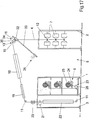
- FIG. 17 shows a further exemplary embodiment of a false twist texturing machine according to the invention shown.
- one machine half is a semi-automatic False twist texturing machine shown. Since both machine halves are mirror images only one half of the double machine is shown in FIG. 17 and described.
- the machine has a frame 2, a winding frame 1 and a process frame 3.
- the frame 2 there are several Supply coils 7 are arranged one above the other in tiers.
- an operating / doffing 5 is formed between the gate frame 2 and the winding frame 1, an operating / doffing 5 is formed.
- the first delivery unit 13 Above the machine frames are the first delivery unit 13, the heating device 18, on one level and the cooling device 19 are arranged.
- a false twister 20 and a second delivery plant 21 are based on the process frame 3.
- the process frame 3 is on the arranged opposite to the gate frame side of the winding frame. winding frame 1 and process frame 3 are joined together directly.
- a second heater 22 is arranged below the second delivery unit 21.
- the Winding frame 1 is used to hold the winding device 9.
- each of the winders is wound into a bobbin 25.
- the thread spool 25 is arranged on a spindle which is driven by a friction roller 24 becomes.
- a traversing device 26 is inserted in the thread path in front of the thread spool.
- the first delivery mechanism 13 is formed by a conveyor roller 30.
- the conveyor roller 30 is with a drive (not shown here) on a height adjustable Carriage 32 attached.
- the carriage 32 can run along the guide 33 between an operating position 35 and the operating position 34 are moved.
- the thread 4 is in the straight thread run by the head thread guides 12 of the frame 2 led to the conveyor roller 30 and from there into the False twist zone of the machine.
- the false twist zone is due to the false twist unit 20 and the conveyor roller 30 limited.
- the heater is within the false twist zone 18 and the cooling device 19 arranged in one plane. At the exit of the The wrongly twisted thread reaches the cooling device 19 via a deflection roller 11 the false twist unit 20.
- the second delivery unit 21 leads the thread from the False twist zone in the downstream second heater 22. From there the Thread via a third delivery mechanism 23 to the winding device 9. In the winding device 9, the thread is then wound into a thread spool 25.
- the bobbin is changed by means of a doffing device performed on the false twist texturing machine.
- a doffing device performed on the false twist texturing machine.
- Handling devices arranged on the doffer, which are preferably pneumatic operate.
- the doffer moves into the operating / doffing gear 5 a, so that the spool change by means of the handling devices is carried out simultaneously in each winding device 9.
- the threads are first brought together into a bundle, cut and vacuumed. The full coils are unlocked and removed. In every rewinder an empty tube is then inserted. The threads are inserted for winding. Every operation is carried out by the handling facilities of the doffer. The new winding process in the winding device can begin.
- This semi-automatic false twist texturing machine can also be a special one realize gentle yarn processing.
- By arranging the first delivery plant immediately in front of the heater inlet of the heater 18 and above the creel frame 2 is a thread run with few deflections.
Applications Claiming Priority (11)
| Application Number | Priority Date | Filing Date | Title |
|---|---|---|---|
| DE19704060 | 1997-02-04 | ||
| DE19704060 | 1997-02-04 | ||
| DE19705812 | 1997-02-15 | ||
| DE19705811 | 1997-02-15 | ||
| DE19705811 | 1997-02-15 | ||
| DE19705812 | 1997-02-15 | ||
| DE19726681 | 1997-06-24 | ||
| DE19726681 | 1997-06-24 | ||
| DE19727011 | 1997-06-25 | ||
| DE19727011 | 1997-06-25 | ||
| EP98905392A EP0906459B1 (de) | 1997-02-04 | 1998-02-03 | Falschdrall-texturiermaschine |
Related Parent Applications (1)
| Application Number | Title | Priority Date | Filing Date |
|---|---|---|---|
| EP98905392A Division EP0906459B1 (de) | 1997-02-04 | 1998-02-03 | Falschdrall-texturiermaschine |
Publications (3)
| Publication Number | Publication Date |
|---|---|
| EP1178139A2 true EP1178139A2 (de) | 2002-02-06 |
| EP1178139A3 EP1178139A3 (de) | 2002-12-11 |
| EP1178139B1 EP1178139B1 (de) | 2005-04-27 |
Family
ID=27512558
Family Applications (2)
| Application Number | Title | Priority Date | Filing Date |
|---|---|---|---|
| EP01124280A Expired - Lifetime EP1178139B1 (de) | 1997-02-04 | 1998-02-03 | Falschdrall-Texturiermaschine |
| EP98905392A Expired - Lifetime EP0906459B1 (de) | 1997-02-04 | 1998-02-03 | Falschdrall-texturiermaschine |
Family Applications After (1)
| Application Number | Title | Priority Date | Filing Date |
|---|---|---|---|
| EP98905392A Expired - Lifetime EP0906459B1 (de) | 1997-02-04 | 1998-02-03 | Falschdrall-texturiermaschine |
Country Status (9)
| Country | Link |
|---|---|
| US (1) | US6209302B1 (is) |
| EP (2) | EP1178139B1 (is) |
| JP (2) | JP4001634B2 (is) |
| CN (1) | CN1079853C (is) |
| DE (2) | DE59812760D1 (is) |
| ID (1) | ID21022A (is) |
| TR (1) | TR199801604T1 (is) |
| TW (1) | TW426761B (is) |
| WO (1) | WO1998033963A1 (is) |
Cited By (4)
| Publication number | Priority date | Publication date | Assignee | Title |
|---|---|---|---|---|
| WO2003027369A1 (de) * | 2001-09-21 | 2003-04-03 | Saurer Gmbh & Co. Kg | Verfahren zur steuerung einer texturiermaschine sowie eine texturiermaschine |
| CN101363151B (zh) * | 2007-08-06 | 2011-06-15 | 浙江日发纺织机械有限公司 | 纺纱器转杯刹车装置 |
| CN103014965A (zh) * | 2012-12-28 | 2013-04-03 | 无锡宏源机电科技有限公司 | 移丝装置 |
| WO2015055399A3 (de) * | 2013-10-14 | 2015-06-18 | Oerlikon Textile Gmbh & Co. Kg | Vorrichtung zum extrudieren, verstrecken und aufwickeln einer schar von folienbändchen |
Families Citing this family (26)
| Publication number | Priority date | Publication date | Assignee | Title |
|---|---|---|---|---|
| TW583357B (en) * | 1998-05-22 | 2004-04-11 | Barmag Barmer Maschf | Texturing machine |
| DE59913648D1 (de) | 1998-10-12 | 2006-08-17 | Saurer Gmbh & Co Kg | Texturiermaschine |
| DE10026942A1 (de) * | 2000-05-30 | 2001-12-06 | Barmag Barmer Maschf | Verfahren zur Steuerung einer Texturiermaschine sowie eine Texturiermaschine |
| WO2002038843A2 (de) * | 2000-11-09 | 2002-05-16 | Barmag Ag | Texturiermaschine und verfahren zum anlegen eines laufenden fadens |
| DE10130389A1 (de) * | 2001-06-23 | 2003-01-02 | Barmag Barmer Maschf | Falschdralltexturiermaschine |
| DE10218748A1 (de) * | 2002-04-26 | 2003-11-13 | Barmag Barmer Maschf | Texturmaschine |
| FR2870838B1 (fr) * | 2004-06-01 | 2006-07-07 | Rieter Textile Machinery Fr | Procede de pilotage des organes d'entrainement lineaire d'un produit filiforme notamment un fil textile pendant la phase de demarrage |
| US20060040090A1 (en) * | 2004-08-17 | 2006-02-23 | Frink Robert A | High luster fiber materials, methods of manufacture and uses thereof |
| DE102006040065A1 (de) * | 2006-08-26 | 2008-02-28 | Oerlikon Textile Gmbh & Co. Kg | Verfahren zur thermischen Behandlung eines laufenden Garns sowie Zwirnmaschine zur Durchführung des Verfahrens |
| DE102008033843A1 (de) * | 2008-07-19 | 2010-01-21 | Oerlikon Textile Gmbh & Co. Kg | Falschdralltexturiermaschine |
| DE102008064307A1 (de) * | 2008-12-20 | 2010-07-01 | Oerlikon Textile Gmbh & Co. Kg | Vorrichtung zum Texturieren und Aufwickeln mehrerer Fäden |
| CN101824688A (zh) * | 2010-04-30 | 2010-09-08 | 江苏宏源纺机股份有限公司 | 弹力丝机 |
| TW201242882A (en) * | 2010-11-06 | 2012-11-01 | Oerlikon Textile Components | Twist stop roller |
| CN102108572B (zh) * | 2011-03-02 | 2013-03-13 | 经纬纺织机械股份有限公司 | 假捻变形机生头拉杆装置 |
| CN102644135B (zh) * | 2012-04-28 | 2016-08-03 | 福建省百川资源再生科技股份有限公司 | 改进型的m型加弹机及其悬挂式轴承结构 |
| WO2014198631A1 (de) * | 2013-06-11 | 2014-12-18 | Oerlikon Textile Gmbh & Co. Kg | Texturiermaschine |
| JP6457342B2 (ja) * | 2014-07-03 | 2019-01-23 | Tmtマシナリー株式会社 | 仮撚加工機、及び、仮撚加工機の糸掛け方法 |
| JP6317239B2 (ja) * | 2014-11-19 | 2018-04-25 | Tmtマシナリー株式会社 | 仮撚加工機 |
| CN104568412B (zh) * | 2015-01-07 | 2017-04-12 | 浙江理工大学 | 一种多参数连续调节的退捻腔实验装置及其实验方法 |
| CN105369415A (zh) * | 2015-12-18 | 2016-03-02 | 浙江汇隆新材料股份有限公司 | 加弹机用粗旦poy原丝退绕张力平衡装置 |
| CN207249402U (zh) | 2017-10-13 | 2018-04-17 | 欧瑞康纺织有限及两合公司 | 一种具有控制系统的假捻变形机 |
| JP7128575B2 (ja) * | 2018-03-16 | 2022-08-31 | Tmtマシナリー株式会社 | 仮撚加工機 |
| DE102019004302A1 (de) * | 2019-05-29 | 2020-12-03 | Detlef Görgens | Antriebseinheit, mit fadenspannungsgesteuerter Spindeldrehzahl des Falschzwirnkräuselaggregats in einer Texturiermaschine |
| JP6822708B1 (ja) * | 2020-03-25 | 2021-01-27 | 株式会社Itoi生活文化研究所 | 複合紙糸及び該製造装置並びに該製造方法 |
| CN115506059B (zh) * | 2022-09-20 | 2024-01-05 | 嘉兴市百达喷织有限公司 | 一种假捻变形机及其换丝方法 |
| CN117262895B (zh) * | 2023-11-23 | 2024-02-02 | 吴江市兰天织造有限公司 | 一种络丝机收卷预处理设备及方法 |
Citations (13)
| Publication number | Priority date | Publication date | Assignee | Title |
|---|---|---|---|---|
| US3645081A (en) * | 1969-10-31 | 1972-02-29 | Spinner Oy | Machine for crimping thermoplastic filament |
| US3772869A (en) * | 1970-02-27 | 1973-11-20 | Zinser Textilmaschinen Gmbh | Twist stopping device |
| FR2226489A1 (en) * | 1973-04-19 | 1974-11-15 | Chavanoz Sa | Yarn texturing device using false twist bush - with pneumatic device for advancing yarn from bush to take-up device |
| DE2426276A1 (de) * | 1974-05-29 | 1975-12-11 | Pensensky Ni Ex K I Pryadilnyc | Antrieb fuer zwirnorgane von spinn- und zwirnmaschinen |
| DE2530125A1 (de) * | 1975-07-05 | 1977-02-03 | Barmag Barmer Maschf | Falschzwirnkraeuselmaschine |
| US4058961A (en) * | 1975-07-05 | 1977-11-22 | Barmag Barmer Maschinenfabrik Aktiengesellschaft | False twist-crimping machine |
| CH594756A5 (en) * | 1976-04-02 | 1978-01-31 | Walter Ernst | Twist run preventing device |
| US4993219A (en) * | 1988-02-13 | 1991-02-19 | Murata Kikai Kabushiki Kaisha | False twist processing apparatus |
| EP0460799A1 (en) * | 1990-05-26 | 1991-12-11 | Rieter Scragg Limited | False twist apparatus |
| EP0638675A1 (en) * | 1993-08-09 | 1995-02-15 | TEIJIN SEIKI CO. Ltd. | Heater with a twist stopping device |
| EP0641877A2 (en) * | 1993-09-04 | 1995-03-08 | B a r m a g AG | False twist crimping machine |
| EP0763612A2 (en) * | 1995-09-14 | 1997-03-19 | Murata Kikai Kabushiki Kaisha | A yarn threading method and device for a false twister |
| DE19652620A1 (de) * | 1995-12-20 | 1997-06-26 | Barmag Barmer Maschf | Falschdralltexturiermaschine, insbesondere Strecktexturiermaschine für sythetische Fäden |
Family Cites Families (13)
| Publication number | Priority date | Publication date | Assignee | Title |
|---|---|---|---|---|
| US4051650A (en) * | 1975-06-17 | 1977-10-04 | Asa S.A. | Yarn texturizing machine |
| USRE30159E (en) | 1975-07-05 | 1979-11-27 | Barmag Barmer Maschinenfabrik Aktiengesellschaft | False twist-crimping machine |
| FR2459847A1 (fr) * | 1979-06-25 | 1981-01-16 | Asa Sa | Machine pour la texturation de fils par fausse torsion |
| DE3324243A1 (de) | 1982-07-09 | 1984-02-16 | Barmag Barmer Maschinenfabrik Ag, 5630 Remscheid | Falschzwirnkraeuselmaschine und verfahren zur ueberbrueckung kurzzeitiger spannun gsausfaelle an textilmaschinen |
| US4581883A (en) * | 1983-11-21 | 1986-04-15 | Barmag Barmer Maschinenfabrik Ag | Yarn false twisting apparatus |
| JPS60126337A (ja) * | 1983-12-07 | 1985-07-05 | 東レ株式会社 | 高伸縮性加工糸の製造方法 |
| DE3623370A1 (de) | 1985-07-13 | 1987-01-29 | Barmag Barmer Maschf | Texturiermaschine |
| DE3801506C2 (de) * | 1987-02-05 | 1996-09-19 | Barmag Barmer Maschf | Falschzwirnkräuselmaschine |
| US4905468A (en) * | 1988-02-22 | 1990-03-06 | Teijin Seiki Company Limited | False twister |
| DE59007713D1 (de) | 1989-08-09 | 1994-12-22 | Barmag Barmer Maschf | Heizeinrichtung. |
| GB9202397D0 (en) * | 1992-02-05 | 1992-03-18 | British Tech Group | Texturing yarn |
| CN1045320C (zh) | 1992-10-08 | 1999-09-29 | 巴马格股份公司 | 假捻卷曲机 |
| EP0744480B1 (de) | 1995-05-23 | 1999-09-15 | B a r m a g AG | Falschdrallaggregat |
-
1998
- 1998-02-03 DE DE59812760T patent/DE59812760D1/de not_active Expired - Fee Related
- 1998-02-03 TR TR1998/01604T patent/TR199801604T1/xx unknown
- 1998-02-03 DE DE59804187T patent/DE59804187D1/de not_active Expired - Fee Related
- 1998-02-03 EP EP01124280A patent/EP1178139B1/de not_active Expired - Lifetime
- 1998-02-03 US US09/155,621 patent/US6209302B1/en not_active Expired - Fee Related
- 1998-02-03 CN CN98800090A patent/CN1079853C/zh not_active Expired - Fee Related
- 1998-02-03 ID IDW980112D patent/ID21022A/id unknown
- 1998-02-03 EP EP98905392A patent/EP0906459B1/de not_active Expired - Lifetime
- 1998-02-03 JP JP53255598A patent/JP4001634B2/ja not_active Expired - Fee Related
- 1998-02-03 WO PCT/EP1998/000573 patent/WO1998033963A1/de active IP Right Grant
- 1998-02-04 TW TW087101413A patent/TW426761B/zh not_active IP Right Cessation
-
2007
- 2007-03-30 JP JP2007093758A patent/JP2007211391A/ja not_active Withdrawn
Patent Citations (13)
| Publication number | Priority date | Publication date | Assignee | Title |
|---|---|---|---|---|
| US3645081A (en) * | 1969-10-31 | 1972-02-29 | Spinner Oy | Machine for crimping thermoplastic filament |
| US3772869A (en) * | 1970-02-27 | 1973-11-20 | Zinser Textilmaschinen Gmbh | Twist stopping device |
| FR2226489A1 (en) * | 1973-04-19 | 1974-11-15 | Chavanoz Sa | Yarn texturing device using false twist bush - with pneumatic device for advancing yarn from bush to take-up device |
| DE2426276A1 (de) * | 1974-05-29 | 1975-12-11 | Pensensky Ni Ex K I Pryadilnyc | Antrieb fuer zwirnorgane von spinn- und zwirnmaschinen |
| DE2530125A1 (de) * | 1975-07-05 | 1977-02-03 | Barmag Barmer Maschf | Falschzwirnkraeuselmaschine |
| US4058961A (en) * | 1975-07-05 | 1977-11-22 | Barmag Barmer Maschinenfabrik Aktiengesellschaft | False twist-crimping machine |
| CH594756A5 (en) * | 1976-04-02 | 1978-01-31 | Walter Ernst | Twist run preventing device |
| US4993219A (en) * | 1988-02-13 | 1991-02-19 | Murata Kikai Kabushiki Kaisha | False twist processing apparatus |
| EP0460799A1 (en) * | 1990-05-26 | 1991-12-11 | Rieter Scragg Limited | False twist apparatus |
| EP0638675A1 (en) * | 1993-08-09 | 1995-02-15 | TEIJIN SEIKI CO. Ltd. | Heater with a twist stopping device |
| EP0641877A2 (en) * | 1993-09-04 | 1995-03-08 | B a r m a g AG | False twist crimping machine |
| EP0763612A2 (en) * | 1995-09-14 | 1997-03-19 | Murata Kikai Kabushiki Kaisha | A yarn threading method and device for a false twister |
| DE19652620A1 (de) * | 1995-12-20 | 1997-06-26 | Barmag Barmer Maschf | Falschdralltexturiermaschine, insbesondere Strecktexturiermaschine für sythetische Fäden |
Cited By (6)
| Publication number | Priority date | Publication date | Assignee | Title |
|---|---|---|---|---|
| WO2003027369A1 (de) * | 2001-09-21 | 2003-04-03 | Saurer Gmbh & Co. Kg | Verfahren zur steuerung einer texturiermaschine sowie eine texturiermaschine |
| CN101363151B (zh) * | 2007-08-06 | 2011-06-15 | 浙江日发纺织机械有限公司 | 纺纱器转杯刹车装置 |
| CN103014965A (zh) * | 2012-12-28 | 2013-04-03 | 无锡宏源机电科技有限公司 | 移丝装置 |
| CN103014965B (zh) * | 2012-12-28 | 2015-10-28 | 无锡宏源机电科技股份有限公司 | 移丝装置 |
| WO2015055399A3 (de) * | 2013-10-14 | 2015-06-18 | Oerlikon Textile Gmbh & Co. Kg | Vorrichtung zum extrudieren, verstrecken und aufwickeln einer schar von folienbändchen |
| US10730716B2 (en) | 2013-10-14 | 2020-08-04 | Oerlikon Textile Gmbh & Co. Kg | Device for extruding, stretching, and winding a group of film strips |
Also Published As
| Publication number | Publication date |
|---|---|
| WO1998033963A1 (de) | 1998-08-06 |
| EP1178139A3 (de) | 2002-12-11 |
| TW426761B (en) | 2001-03-21 |
| DE59804187D1 (de) | 2002-06-27 |
| JP4001634B2 (ja) | 2007-10-31 |
| CN1079853C (zh) | 2002-02-27 |
| DE59812760D1 (de) | 2005-06-02 |
| EP0906459A1 (de) | 1999-04-07 |
| TR199801604T1 (xx) | 2002-05-21 |
| CN1216076A (zh) | 1999-05-05 |
| EP1178139B1 (de) | 2005-04-27 |
| EP0906459B1 (de) | 2002-05-22 |
| US6209302B1 (en) | 2001-04-03 |
| JP2007211391A (ja) | 2007-08-23 |
| JP2000508724A (ja) | 2000-07-11 |
| ID21022A (id) | 1999-04-08 |
Similar Documents
| Publication | Publication Date | Title |
|---|---|---|
| EP1178139B1 (de) | Falschdrall-Texturiermaschine | |
| EP0845550B1 (de) | Verfahren und Vorrichtungen zum Spinnen und Aufwickeln von Fäden | |
| EP1527217B1 (de) | Vorrichtung zum spinnen und aufwickeln | |
| EP2147137B1 (de) | Vorrichtung zum schmelzspinnen und aufwickeln synthetischer fäden | |
| WO2011009498A1 (de) | Verfahren zum schmelzspinnen, verstrecken und aufwickeln eines multifilen fadens sowie eine vorrichtung zur durchführung des verfahrens | |
| EP1979513A1 (de) | Vorrichtung zum schmelzspinnen und aufwickeln von synthetischen fäden | |
| DE10026942A1 (de) | Verfahren zur Steuerung einer Texturiermaschine sowie eine Texturiermaschine | |
| DE10053073A1 (de) | Spinnvorrichtung | |
| EP1038058B1 (de) | Texturiermaschine | |
| EP2358932B1 (de) | Vorrichtung zum texturieren und aufwickeln mehrerer fäden | |
| EP1446521B1 (de) | Texturiermaschine | |
| EP1523592A1 (de) | Falschdralltexturiermaschine | |
| EP1409777B1 (de) | Falschdralltexturiermaschine | |
| DE19801150C2 (de) | Texturiermaschine | |
| DE3817679C1 (en) | Cabling machine | |
| DE19705810A1 (de) | Falschdrall-Texturiermaschine | |
| WO2019030134A1 (de) | Vorrichtung zum abziehen und aufwickeln einer fadenschar | |
| DE4130059C2 (de) | Maschine zum Behandeln synthetischer, multifiler Endlosfäden | |
| DE10207086A1 (de) | Texturiermaschine | |
| DE19705804A1 (de) | Falschdrall-Texturiermaschine | |
| EP0684202B1 (de) | Maschine zum Bearbeiten synthetischer Fäden | |
| DE3007387A1 (de) | Splitting-winder | |
| WO2014170185A1 (de) | Texturiermaschine | |
| DE19535747A1 (de) | Verfahren und Vorrichtung zum Tangeln eines Multifilamentfadens | |
| DE19503561A1 (de) | Mehrzonenstreckwerk für Textilmaschinen |
Legal Events
| Date | Code | Title | Description |
|---|---|---|---|
| PUAI | Public reference made under article 153(3) epc to a published international application that has entered the european phase |
Free format text: ORIGINAL CODE: 0009012 |
|
| AC | Divisional application: reference to earlier application |
Ref document number: 906459 Country of ref document: EP |
|
| AK | Designated contracting states |
Kind code of ref document: A2 Designated state(s): CH DE FR GB IT LI |
|
| RIN1 | Information on inventor provided before grant (corrected) |
Inventor name: BERGES, DIETRICH Inventor name: WORTMANN, THOMAS Inventor name: BRUSKE, JOHANNES Inventor name: LORENZ, HELLMUT |
|
| PUAL | Search report despatched |
Free format text: ORIGINAL CODE: 0009013 |
|
| AK | Designated contracting states |
Kind code of ref document: A3 Designated state(s): CH DE FR GB IT LI |
|
| RIC1 | Information provided on ipc code assigned before grant |
Free format text: 7D 02G 1/02 A, 7B 65H 51/06 B, 7B 65H 57/14 B, 7B 65H 59/16 B |
|
| 17P | Request for examination filed |
Effective date: 20030206 |
|
| AKX | Designation fees paid |
Designated state(s): CH DE FR GB IT LI |
|
| 17Q | First examination report despatched |
Effective date: 20030723 |
|
| RAP1 | Party data changed (applicant data changed or rights of an application transferred) |
Owner name: SAURER GMBH & CO. KG |
|
| GRAP | Despatch of communication of intention to grant a patent |
Free format text: ORIGINAL CODE: EPIDOSNIGR1 |
|
| GRAS | Grant fee paid |
Free format text: ORIGINAL CODE: EPIDOSNIGR3 |
|
| GRAA | (expected) grant |
Free format text: ORIGINAL CODE: 0009210 |
|
| AC | Divisional application: reference to earlier application |
Ref document number: 0906459 Country of ref document: EP Kind code of ref document: P |
|
| AK | Designated contracting states |
Kind code of ref document: B1 Designated state(s): CH DE FR GB IT LI |
|
| REG | Reference to a national code |
Ref country code: GB Ref legal event code: FG4D Free format text: NOT ENGLISH |
|
| REG | Reference to a national code |
Ref country code: CH Ref legal event code: EP |
|
| REF | Corresponds to: |
Ref document number: 59812760 Country of ref document: DE Date of ref document: 20050602 Kind code of ref document: P |
|
| GBT | Gb: translation of ep patent filed (gb section 77(6)(a)/1977) |
Effective date: 20050810 |
|
| PGFP | Annual fee paid to national office [announced via postgrant information from national office to epo] |
Ref country code: GB Payment date: 20060208 Year of fee payment: 9 |
|
| PLBE | No opposition filed within time limit |
Free format text: ORIGINAL CODE: 0009261 |
|
| STAA | Information on the status of an ep patent application or granted ep patent |
Free format text: STATUS: NO OPPOSITION FILED WITHIN TIME LIMIT |
|
| ET | Fr: translation filed | ||
| 26N | No opposition filed |
Effective date: 20060130 |
|
| PGFP | Annual fee paid to national office [announced via postgrant information from national office to epo] |
Ref country code: CH Payment date: 20070213 Year of fee payment: 10 |
|
| PGFP | Annual fee paid to national office [announced via postgrant information from national office to epo] |
Ref country code: DE Payment date: 20070425 Year of fee payment: 10 |
|
| GBPC | Gb: european patent ceased through non-payment of renewal fee |
Effective date: 20070203 |
|
| PGFP | Annual fee paid to national office [announced via postgrant information from national office to epo] |
Ref country code: IT Payment date: 20070614 Year of fee payment: 10 |
|
| PG25 | Lapsed in a contracting state [announced via postgrant information from national office to epo] |
Ref country code: GB Free format text: LAPSE BECAUSE OF NON-PAYMENT OF DUE FEES Effective date: 20070203 |
|
| PGFP | Annual fee paid to national office [announced via postgrant information from national office to epo] |
Ref country code: FR Payment date: 20070209 Year of fee payment: 10 |
|
| REG | Reference to a national code |
Ref country code: CH Ref legal event code: PL |
|
| PG25 | Lapsed in a contracting state [announced via postgrant information from national office to epo] |
Ref country code: CH Free format text: LAPSE BECAUSE OF NON-PAYMENT OF DUE FEES Effective date: 20080229 Ref country code: LI Free format text: LAPSE BECAUSE OF NON-PAYMENT OF DUE FEES Effective date: 20080229 |
|
| REG | Reference to a national code |
Ref country code: FR Ref legal event code: ST Effective date: 20081031 |
|
| PG25 | Lapsed in a contracting state [announced via postgrant information from national office to epo] |
Ref country code: DE Free format text: LAPSE BECAUSE OF NON-PAYMENT OF DUE FEES Effective date: 20080902 |
|
| PG25 | Lapsed in a contracting state [announced via postgrant information from national office to epo] |
Ref country code: FR Free format text: LAPSE BECAUSE OF NON-PAYMENT OF DUE FEES Effective date: 20080229 |
|
| PG25 | Lapsed in a contracting state [announced via postgrant information from national office to epo] |
Ref country code: IT Free format text: LAPSE BECAUSE OF NON-PAYMENT OF DUE FEES Effective date: 20080203 |