EP1172844A2 - Verfahren und Vorrichtung zur Substratreinigung - Google Patents
Verfahren und Vorrichtung zur Substratreinigung Download PDFInfo
- Publication number
- EP1172844A2 EP1172844A2 EP01116941A EP01116941A EP1172844A2 EP 1172844 A2 EP1172844 A2 EP 1172844A2 EP 01116941 A EP01116941 A EP 01116941A EP 01116941 A EP01116941 A EP 01116941A EP 1172844 A2 EP1172844 A2 EP 1172844A2
- Authority
- EP
- European Patent Office
- Prior art keywords
- liquid
- substrate cleaning
- substrate
- measuring
- cleaning
- Prior art date
- Legal status (The legal status is an assumption and is not a legal conclusion. Google has not performed a legal analysis and makes no representation as to the accuracy of the status listed.)
- Withdrawn
Links
Images


Classifications
-
- H10P52/00—
-
- H10P70/15—
-
- B—PERFORMING OPERATIONS; TRANSPORTING
- B08—CLEANING
- B08B—CLEANING IN GENERAL; PREVENTION OF FOULING IN GENERAL
- B08B3/00—Cleaning by methods involving the use or presence of liquid or steam
-
- H10P72/0426—
-
- Y—GENERAL TAGGING OF NEW TECHNOLOGICAL DEVELOPMENTS; GENERAL TAGGING OF CROSS-SECTIONAL TECHNOLOGIES SPANNING OVER SEVERAL SECTIONS OF THE IPC; TECHNICAL SUBJECTS COVERED BY FORMER USPC CROSS-REFERENCE ART COLLECTIONS [XRACs] AND DIGESTS
- Y10—TECHNICAL SUBJECTS COVERED BY FORMER USPC
- Y10S—TECHNICAL SUBJECTS COVERED BY FORMER USPC CROSS-REFERENCE ART COLLECTIONS [XRACs] AND DIGESTS
- Y10S438/00—Semiconductor device manufacturing: process
- Y10S438/906—Cleaning of wafer as interim step
-
- Y—GENERAL TAGGING OF NEW TECHNOLOGICAL DEVELOPMENTS; GENERAL TAGGING OF CROSS-SECTIONAL TECHNOLOGIES SPANNING OVER SEVERAL SECTIONS OF THE IPC; TECHNICAL SUBJECTS COVERED BY FORMER USPC CROSS-REFERENCE ART COLLECTIONS [XRACs] AND DIGESTS
- Y10—TECHNICAL SUBJECTS COVERED BY FORMER USPC
- Y10T—TECHNICAL SUBJECTS COVERED BY FORMER US CLASSIFICATION
- Y10T436/00—Chemistry: analytical and immunological testing
- Y10T436/11—Automated chemical analysis
- Y10T436/115831—Condition or time responsive
Definitions
- the present invention relates to a substrate cleaning method and a substrate cleaning apparatus for cleaning a substrate, which use, as a cleaning liquid, an aqueous solution of ammonium fluoride or a mixture of an aqueous solution of ammonium fluoride and hydrofluoric acid. More particularly, the present invention is concerned with a novel substrate cleaning method and a novel substrate cleaning apparatus, which are developed for achieving both uniform and stable cleaning treatment and reduction in the amount of the cleaning liquid used.
- An aqueous solution of ammonium fluoride (including arbitrary mixtures of hydrofluoric acid and ammonia, and ones containing a surfactant) is widely used in the form of a mixture thereof with hydrofluoric acid and the like for cleaning or etching a semiconductor (mainly a silicon oxide film) substrate or a glass substrate in the production process for semiconductor or liquid crystal display (LCD).
- a semiconductor mainly a silicon oxide film
- LCD liquid crystal display
- a cleaning liquid for example, an aqueous solution of ammonium fluoride, a mixture of an aqueous solution of ammonium fluoride and hydrofluoric acid as mentioned above, or other chemical liquids
- a higher accuracy treatment is desired.
- the chemical component content such as ammonium fluoride (NH 4 F), and hydrogen fluoride (HF)
- moisture content of the cleaning liquid change (evaporate) with the lapse of time. Therefore, such cleaning or etching has a problem in that the etching rate for a silicon oxide film or a glass substrate changes (increases).
- a great amount of the cleaning liquid is required.
- a cleaning liquid containing ammonium fluoride is used in an ammonium fluoride concentration as high as several tens % (for example, about 40 % by weight), and hence, the amount of the chemical consumed per liquid replacement in this cleaning liquid is large, as compared to those in other cleaning liquids generally used in a chemical concentration of about several %. Accordingly, the amounts of the ammonium fluoride and hydrofluoric acid used (cost for chemicals) are to increase.
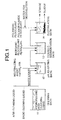
- a waste water treatment shown in Fig. 1 is needed, and, in this treatment, a large amount of resource (waste water treatment agent) is consumed, resulting in a large amount of waste products (waste water and sludge)(see Fig. 2).
- Fig. 1 is an explanatory view illustrating a process for treating the effluent of a cleaning liquid.
- Effluent produced in a cleaning bath 11 is transferred to a pH-adjusting bath 12, and neutralized in this bath by, for example, a 20 % aqueous solution of calcium hydroxide.
- the effluent is transferred to a coagulo-sedimentation bath 13 and subjected to coagulation and sedimentation by a chemical, such as aluminum sulfate, and then, in a flocculation bath 14, is flocculated by a polymeric flocculant, such as a polyacrylamide flocculant, and subjected to sedimentation, followed by discharge in the form of sewage and sludge.
- a polymeric flocculant such as a polyacrylamide flocculant
- a substrate cleaning method and a substrate cleaning apparatus which enable a resource saving and a reduction in waste to be achieved.
- the present invention also provides a substrate cleaning method which is developed for achieving both the uniform and stable cleaning treatment and the reduction in the amount of the cleaning liquid used.
- the present invention provides a substrate cleaning apparatus which is developed for achieving both uniform and stable cleaning treatment and reduction in the amount of the cleaning liquid used.
- a substrate cleaning method and a substrate cleaning apparatus which use an aqueous solution of ammonium fluoride or a mixture of an aqueous solution of ammonium fluoride and hydrofluoric acid as a cleaning liquid is also provided according to the present invention.
- Fig. 1 is an explanatory view illustrating a process for treating an effluent of a cleaning liquid, which is the related art.
- Fig. 2 is a diagram showing a resource (chemicals) required for an effluent treatment for a cleaning liquid, which is the related art.
- Fig. 3 is a graph showing the relationship between time and etching rate with respect to the cleaning liquid.
- Fig. 4 is a graph showing the relationship between the time and the HF concentration of the cleaning liquid.
- Fig. 5 is a diagrammatic view showing an example of a substrate cleaning apparatus, which is a first embodiment of the present invention.
- Fig. 6 is a graph showing the change in the HF concentration by addition of water according to the present invention.
- Fig. 7 is a graph showing the change in the etching rate by addition of water according to the present invention.
- Fig. 8 is a graph showing the state of controlling the etching rate and the HF concentration by addition of water according to the present invention.
- Fig. 9 is a diagrammatic view showing a substrate cleaning apparatus, which is a second embodiment of the present invention.
- Fig. 10 is a diagrammatic view showing an example of a substrate cleaning apparatus in which an aqueous ammonia storage tank is provided, which is a third embodiment of the present invention.
- Fig. 11 is a diagrammatic view showing an example of a substrate cleaning apparatus in which an aqueous ammonia storage tank is provided, which is a fourth embodiment of the present invention.
- the cleaning liquid in the cleaning (or etching) treatment of a substrate using, as a treatment liquid (or a cleaning liquid), an aqueous solution of ammonium fluoride or a mixture of an aqueous solution of ammonium fluoride and hydrofluoric acid, the cleaning liquid is replenished by at least one liquid selected from the group consisting of water, ammonia, aqueous ammonia, and an aqueous solution of ammonium fluoride according to the accumulative time for using the cleaning liquid and the individual component concentrations of the cleaning liquid.
- Fig. 3 shows the relationship between the lapse of time and the etching rate for a thermal oxide film with respect to the mixture of ammonium fluoride and hydrofluoric acid.
- the cleaning liquid has a composition such that the NH 4 F (40 %):HF (50 %) ratio is 400:1, and the temperature of the cleaning liquid is 25°C and the thermal oxide film is comprised of SiO 2 .
- the time is taken as the abscissa and represented by a unit of "days”
- the etching rate for a substrate is taken as the ordinate and represented by a unit of the etching rate per minute, i.e., " ⁇ /min”.
- the etching rate changes with time as follows: after a lapse of 0 day, the etching rate is about 34 ⁇ /min; after a lapse of 11 days, the etching rate is 70 ⁇ /min; and after a lapse of 22 days, the etching rate is 95 ⁇ / min.
- the etching rate for the thermal oxide film remarkably increases with the lapse of time.
- the etching rate changes with time, and there is a very good correlation (proportionality relation) between the etching rate and the time.
- the moisture content and chemical component such as ammonium fluoride (NH 4 F) and hydrogen fluoride (HF)
- NH 4 F ammonium fluoride
- HF hydrogen fluoride
- Fig. 4 shows the change in the HF concentration of the cleaning liquid with the lapse of time.
- the time is taken as the abscissa and represented by a unit of "days”, and ranges from 0 to 25 days.
- the HF concentration of the mixture is taken as the ordinate and represented by a unit of "% by weight (wt%)", and ranges from 0 to 0.6 wt% and is shown in a scale of 0.1 wt%.
- the HF concentration is 0.1 wt%; after a lapse of 11 days, the HF concentration is 0.35 wt%; and after a lapse of 22 days, the HF concentration is 4.7 wt%.
- the HF concentration of the cleaning liquid is required to be kept constant.
- a most effective method is the one in which water that readily evaporates from the cleaning liquid is appropriately added to the cleaning liquid.
- Fig. 5 shows an example of the construction of the substrate cleaning apparatus according to the present invention.
- This substrate cleaning apparatus comprises a substrate treatment bath 21 for storing therein a cleaning liquid comprising, for example, a mixture of ammonium fluoride and hydrofluoric acid, and for subjecting a substrate to cleaning treatment, and a circulation pump 22 for circulating the cleaning liquid which is the overflow back to the substrate treatment bath 21.
- a substrate which is a substance to be treated, is accommodated in a substrate carrier and dipped in the cleaning liquid in the substrate treatment bath 21, and thus performing a cleaning (etching) treatment.
- the characteristic feature of the above apparatus resides in that the substrate treatment'bath 21 is provided with a constant delivery pump 23 and a controller 24, by which feeding water and addition of water through the pump 23 is controlled.
- the HF component concentration of the cleaning liquid increases with the lapse of time at a constant rate, so that the etching rate for the thermal oxide film remarkably increases.
- the HF concentration is controlled by the controller 24 so as to be kept constant by adding water to the substrate treatment bath 21 with the lapse of time by means of the constant delivery pump 23 so that the etching rate is kept substantially constant.
- Fig. 6 shows the change in the HF concentration when water is added.
- the time is taken as the abscissa and represented by a unit of "hours (hrs)", and ranges from 0 to 300 hrs.
- the HF concentration is taken as the ordinate and represented by a unit of "wt%”, and ranges from 2.92 to 3.06 wt%.
- the HF concentration is 2.94 wt%; and after a lapse of 220 hrs, the HF concentration is 3.04 wt%.
- the HF concentration is lowered to 2.95 wt%.
- the HF concentration slightly increases to 2.96 wt%.
- the HF concentration which increases with the lapse of time goes back to the original concentration by addition of water.
- the control of the HF concentration by addition of water leads to the control of the etching rate, and, as shown in Fig. 7, the etching rate is also lowered by the addition of water.
- Fig. 7 is a graph showing the state of controlling the etching rate and HF concentration by addition of water.
- the time is taken as the abscissa and represented by a unit of "hours (hrs)", and ranges from 0 to 250 hours.
- the etching rate is taken as the ordinate and represented by a unit of "nm/min”, and ranges from 65 to 85 nm/min.
- the etching rate is 74 nm/min; after a lapse of 70 hours, the etching rate is 76 nm/min; and after a lapse of 220 hours, the etching rate is 82 nm/min.
- the etching rate is lowered to about 72 nm/min.
- the etching rate and the HF concentration can be kept in a constant range by intermittently adding water.
- FIG. 8 A graph showing the relationship between the etching rate and the hydrofluoric acid concentration when water is intermittently added is illustrated in Fig. 8.
- Fig. 8 shows an example in which water is intermittently added, but the conditions for water addition may be any of continuous addition and intermittent addition. For keeping the concentration constant, the continuous addition is preferred.
- the timing of the addition of water is controlled based on the measurement data, but, as shown in Fig. 9, a concentration measuring unit 35 can be provided to measure the concentration of the cleaning liquid being circulated, so that the addition of water can be controlled based on the concentration data in real time.
- the concentrations of the components (e.g., ammonia, hydrofluoric acid, and water) in the cleaning liquid are individually measured by means of the concentration measuring unit 35, and the measurement result is transmitted to a controller 34 comprised of a computer and a central monitoring unit to determine the addition and calculate the required amount of addition, followed by transmission of an instruction for replenishment to a water feeding line (constant delivery pump 33). Then, whether or not the addition is made in accordance with the instruction is confirmed by a measurement by means of the concentration measuring unit 35.
- a controller 34 comprised of a computer and a central monitoring unit to determine the addition and calculate the required amount of addition, followed by transmission of an instruction for replenishment to a water feeding line (constant delivery pump 33).
- a measurement of an absorbance at a predetermined wavelength, an infrared absorption spectrum, an ultraviolet absorption spectrum, an index of refraction, a specific gravity, a transmittance, or an electric conductivity may be performed and a measuring unit, such as a Karl Fischer moisture titrator or liquid (ion) chromatography may be used.
- Fig. 10 and Fig. 11 show an example in which an aqueous ammonia storage tank 47 or 57 for feeding aqueous ammonia is provided instead of the constant delivery pump 23 or 33 for feeding water in Fig. 5 and Fig. 9, respectively.
- the HF concentration is effectively controlled, so that the etching rate is controlled to be kept constant.
- aqueous ammonia not only aqueous ammonia but also other appropriate aqueous solutions can be used, and further, ammonia gas can also be used.
- ammonia gas can also be used.
- an aqueous solution of ammonium fluoride can be used, and ammonium fluoride can be used in combination with ammonia.
- the etching treatment by the cleaning liquid can be conducted uniformly and stably (namely, the etching rate for an oxide film can be kept constant), so that there is no need to frequently replace the cleaning liquid differing from the conventional cleaning. Therefore, the life time of the cleaning liquid can be prolonged, and the reduction in frequency of the liquid replacement contributes to a reduction in the cleaning liquid consumed (resource saving) and a reduction in the waste water treatment agent required for the waste water treatment of the cleaning liquid (resource saving). Further, the reduction in these chemicals used contributes to a reduction in the amount of sludge and waste water produced upon the waste water treatment (reduction in the amount of waste).
- the present invention not only achieves the uniform and stable substrate treatment but also contributes to resource saving and the reduction in the amount of waste, namely, preservation of the environment.
Landscapes
- Cleaning Or Drying Semiconductors (AREA)
- Cleaning By Liquid Or Steam (AREA)
- Weting (AREA)
- Detergent Compositions (AREA)
Applications Claiming Priority (4)
| Application Number | Priority Date | Filing Date | Title |
|---|---|---|---|
| JP2000214974 | 2000-07-14 | ||
| JP2000214974 | 2000-07-14 | ||
| JP2000240134 | 2000-08-08 | ||
| JP2000240134A JP4590700B2 (ja) | 2000-07-14 | 2000-08-08 | 基板洗浄方法及び基板洗浄装置 |
Publications (2)
| Publication Number | Publication Date |
|---|---|
| EP1172844A2 true EP1172844A2 (de) | 2002-01-16 |
| EP1172844A3 EP1172844A3 (de) | 2005-12-14 |
Family
ID=26596094
Family Applications (1)
| Application Number | Title | Priority Date | Filing Date |
|---|---|---|---|
| EP01116941A Withdrawn EP1172844A3 (de) | 2000-07-14 | 2001-07-11 | Verfahren und Vorrichtung zur Substratreinigung |
Country Status (5)
| Country | Link |
|---|---|
| US (2) | US20020046757A1 (de) |
| EP (1) | EP1172844A3 (de) |
| JP (1) | JP4590700B2 (de) |
| KR (1) | KR100870255B1 (de) |
| TW (1) | TWI245334B (de) |
Cited By (1)
| Publication number | Priority date | Publication date | Assignee | Title |
|---|---|---|---|---|
| US7659212B2 (en) | 2004-03-22 | 2010-02-09 | Mimasu Semiconductor Industry Co., Ltd. | Process control method in spin etching and spin etching apparatus |
Families Citing this family (27)
| Publication number | Priority date | Publication date | Assignee | Title |
|---|---|---|---|---|
| US20060080632A1 (en) * | 2004-09-30 | 2006-04-13 | Mathstar, Inc. | Integrated circuit layout having rectilinear structure of objects |
| US7098099B1 (en) * | 2005-02-24 | 2006-08-29 | Texas Instruments Incorporated | Semiconductor device having optimized shallow junction geometries and method for fabrication thereof |
| JP2007220980A (ja) * | 2006-02-17 | 2007-08-30 | Mitsubishi Electric Corp | 太陽電池セルの製造方法および製造装置 |
| US8511499B2 (en) | 2007-12-18 | 2013-08-20 | Abbott Laboratories | Container |
| MY154493A (en) | 2006-12-27 | 2015-06-30 | Abbott Lab | Container |
| US8226775B2 (en) | 2007-12-14 | 2012-07-24 | Lam Research Corporation | Methods for particle removal by single-phase and two-phase media |
| JP5072892B2 (ja) * | 2008-04-03 | 2012-11-14 | 東京エレクトロン株式会社 | 基板処理装置、基板処理方法及び記憶媒体 |
| JP2012119344A (ja) * | 2009-03-31 | 2012-06-21 | Sharp Corp | 基板洗浄装置 |
| US8627981B2 (en) | 2009-06-05 | 2014-01-14 | Abbott Laboratories | Container |
| US8469223B2 (en) | 2009-06-05 | 2013-06-25 | Abbott Laboratories | Strength container |
| JP5492574B2 (ja) * | 2010-01-08 | 2014-05-14 | 東京エレクトロン株式会社 | 基板のクリーニング方法及び基板のクリーニング装置 |
| US20120048303A1 (en) * | 2010-08-26 | 2012-03-01 | Macronix International Co., Ltd. | Process system and cleaning process |
| IN2014DN08897A (de) | 2012-04-27 | 2015-05-22 | Abbott Lab | |
| USD733320S1 (en) | 2013-04-26 | 2015-06-30 | Abbott Laboratories | Container |
| JP6163434B2 (ja) * | 2014-01-16 | 2017-07-12 | 株式会社東芝 | 薬液処理装置及び薬液処理方法 |
| DE102014103728A1 (de) * | 2014-03-19 | 2015-09-24 | Karl Storz Gmbh & Co. Kg | Automatische Erfassung der Eindringtiefe und/oder der rotatorischen Orientierung eines invasiven Instrumentes |
| US9616459B1 (en) * | 2014-04-17 | 2017-04-11 | Lockheed Martin Corporation | Polymeric coatings for fortification of visible, infrared, and laser optical devices |
| US9982156B1 (en) | 2014-04-17 | 2018-05-29 | Lockheed Martin Corporation | Transmissive surfaces and polymeric coatings therefore, for fortification of visible, infrared, and laser optical devices |
| JP6433730B2 (ja) * | 2014-09-08 | 2018-12-05 | 東芝メモリ株式会社 | 半導体装置の製造方法及び半導体製造装置 |
| EP3015432A1 (de) * | 2014-10-30 | 2016-05-04 | Eliquo Stulz GmbH | Verfahren und Vorrichtung zur Behandlung von organischer Masse mit Faulschlamm-Rückführung |
| JP6383254B2 (ja) * | 2014-11-04 | 2018-08-29 | 株式会社東芝 | 処理装置および処理方法 |
| TWM515418U (zh) * | 2015-07-27 | 2016-01-11 | 盟立自動化股份有限公司 | 用來清洗平板構件之槽體 |
| KR20170029758A (ko) * | 2015-09-08 | 2017-03-16 | 삼성전자주식회사 | 반도체 세정 공정 시스템 및 반도체 장치의 제조 방법 |
| TW201713751A (zh) * | 2015-10-06 | 2017-04-16 | 聯華電子股份有限公司 | 酸槽補酸系統與方法 |
| CN115863225B (zh) * | 2023-02-27 | 2023-05-26 | 合肥新晶集成电路有限公司 | 混酸的补酸控制方法、装置、计算机设备及存储介质 |
| US20260002364A1 (en) * | 2024-06-26 | 2026-01-01 | Siplast, Inc. | Inverted fleece back assemblies for flashing applications |
| CN119426313B (zh) * | 2025-01-08 | 2025-04-15 | 浙江省农业科学院 | 组培瓶灌装流水线水循环控制方法、装置及其可读存储介质 |
Family Cites Families (21)
| Publication number | Priority date | Publication date | Assignee | Title |
|---|---|---|---|---|
| FR1487060A (de) * | 1965-07-30 | 1967-10-11 | ||
| US3705061A (en) * | 1971-03-19 | 1972-12-05 | Southern California Chem Co In | Continuous redox process for dissolving copper |
| JPS5946032A (ja) * | 1982-09-09 | 1984-03-15 | Hitachi Ltd | 洗浄装置 |
| JPS60114579A (ja) * | 1983-11-25 | 1985-06-21 | Hitachi Ltd | エッチング液の制御方法 |
| DK374889D0 (da) * | 1989-07-28 | 1989-07-28 | Koege Kemisk Vaerk | Fremgangsmaade til procesovervaagning |
| JP2632262B2 (ja) * | 1991-08-20 | 1997-07-23 | 大日本スクリーン製造株式会社 | シリコンウエハ上のコンタクトホール内の自然酸化膜の除去方法 |
| JP3074366B2 (ja) * | 1993-02-22 | 2000-08-07 | 東京エレクトロン株式会社 | 処理装置 |
| US6350425B2 (en) * | 1994-01-07 | 2002-02-26 | Air Liquide America Corporation | On-site generation of ultra-high-purity buffered-HF and ammonium fluoride |
| US5472516A (en) * | 1994-04-15 | 1995-12-05 | At&T Corp. | Process and apparatus for semiconductor device fabrication |
| TW294831B (de) * | 1995-04-26 | 1997-01-01 | Handotai Energy Kenkyusho Kk | |
| JPH08334461A (ja) * | 1995-06-07 | 1996-12-17 | Nisso Eng Kk | 半導体ウエハエッチング用バッファードフッ酸の組成測定方法 |
| JP3636504B2 (ja) * | 1995-07-06 | 2005-04-06 | ステラケミファ株式会社 | ウエットプロセス装置及び方法 |
| US5903006A (en) * | 1996-05-31 | 1999-05-11 | Norihiro Kiuchi | Liquid concentration detecting apparatus |
| KR100238234B1 (ko) * | 1997-03-20 | 2000-01-15 | 윤종용 | 반도체소자용 인-시튜 세정장치 및 그를 이용한 반도체 소자의 세정방법 |
| JP3772456B2 (ja) * | 1997-04-23 | 2006-05-10 | 三菱電機株式会社 | 太陽電池及びその製造方法、半導体製造装置 |
| US5972123A (en) | 1997-06-13 | 1999-10-26 | Cfmt, Inc. | Methods for treating semiconductor wafers |
| JP2000150447A (ja) * | 1998-11-10 | 2000-05-30 | Nec Corp | 薬液濃度管理方法、管理装置および薬液処理装置 |
| US6261845B1 (en) * | 1999-02-25 | 2001-07-17 | Cfmt, Inc. | Methods and systems for determining chemical concentrations and controlling the processing of semiconductor substrates |
| EP1149411A1 (de) * | 1999-11-26 | 2001-10-31 | Koninklijke Philips Electronics N.V. | Verfahren und vorrichtung zum nassätzen von halbleitersubstraten |
| US6589884B1 (en) * | 2000-08-31 | 2003-07-08 | Micron Technology, Inc. | Method of forming an inset in a tungsten silicide layer in a transistor gate stack |
| US6767877B2 (en) * | 2001-04-06 | 2004-07-27 | Akrion, Llc | Method and system for chemical injection in silicon wafer processing |
-
2000
- 2000-08-08 JP JP2000240134A patent/JP4590700B2/ja not_active Expired - Fee Related
-
2001
- 2001-07-03 TW TW090116257A patent/TWI245334B/zh not_active IP Right Cessation
- 2001-07-11 EP EP01116941A patent/EP1172844A3/de not_active Withdrawn
- 2001-07-13 US US09/905,662 patent/US20020046757A1/en not_active Abandoned
- 2001-07-13 KR KR1020010042362A patent/KR100870255B1/ko not_active Expired - Fee Related
-
2004
- 2004-09-09 US US10/937,014 patent/US7255749B2/en not_active Expired - Fee Related
Cited By (1)
| Publication number | Priority date | Publication date | Assignee | Title |
|---|---|---|---|---|
| US7659212B2 (en) | 2004-03-22 | 2010-02-09 | Mimasu Semiconductor Industry Co., Ltd. | Process control method in spin etching and spin etching apparatus |
Also Published As
| Publication number | Publication date |
|---|---|
| KR100870255B1 (ko) | 2008-11-25 |
| US20050022845A1 (en) | 2005-02-03 |
| US7255749B2 (en) | 2007-08-14 |
| KR20020007210A (ko) | 2002-01-26 |
| JP2002086084A (ja) | 2002-03-26 |
| US20020046757A1 (en) | 2002-04-25 |
| EP1172844A3 (de) | 2005-12-14 |
| TWI245334B (en) | 2005-12-11 |
| JP4590700B2 (ja) | 2010-12-01 |
Similar Documents
| Publication | Publication Date | Title |
|---|---|---|
| US7255749B2 (en) | Substrate cleaning method and substrate cleaning apparatus | |
| KR0185180B1 (ko) | 반도체 디바이스 제조방법 및 그 제조장치 | |
| US7101517B2 (en) | Processing solution preparation and supply method and apparatus | |
| KR970072163A (ko) | 반도체 질화막 에칭장치 | |
| US6286526B1 (en) | Method for treatment of semiconductor substrate with chemical solution and apparatus used for said treatment | |
| JP3211872B2 (ja) | 薬液処理方法、半導体基板の処理方法及び半導体装置の製造方法 | |
| JP2000150447A (ja) | 薬液濃度管理方法、管理装置および薬液処理装置 | |
| TW508626B (en) | Arrangement and method for detecting the end of life of an aqueous bath utilized in semiconductor processing | |
| JPH0922891A (ja) | ウエットプロセス装置及び方法 | |
| KR950015629A (ko) | 실리콘기판의 세정방법 | |
| KR100664774B1 (ko) | 전자 디바이스 제조 방법 및 장치 | |
| JP4419315B2 (ja) | 基板洗浄方法及び基板洗浄装置 | |
| JP2002143790A (ja) | 基板洗浄方法及び基板洗浄装置 | |
| JP4604320B2 (ja) | 基板洗浄方法及び基板洗浄装置 | |
| JP3430611B2 (ja) | エッチング装置と濃燐酸溶液の処理方法 | |
| JP2002143791A (ja) | 基板洗浄方法及び基板洗浄装置 | |
| KR100524399B1 (ko) | 혼합 세정액 제조 장치 및 이를 이용한 혼합 세정액 제조방법 | |
| JP2003100696A (ja) | 自動濃度調整装置 | |
| JPH02159029A (ja) | 薬液処理方法およびその装置 | |
| JPH05259141A (ja) | 半導体装置の洗浄方法 | |
| JP2000042571A (ja) | フッ素含有排水処理装置 | |
| JPH07306146A (ja) | 溶液の濃度測定方法、濃度測定装置及び洗浄装置 | |
| JP2007260516A (ja) | 硫酸過酸化水素洗浄液による洗浄方法、電気光学パネルの製造方法及び硫酸過酸化水素洗浄装置 | |
| JPH06228776A (ja) | エッチング浴の管理方法 | |
| JP2001098391A (ja) | エッチング方法 |
Legal Events
| Date | Code | Title | Description |
|---|---|---|---|
| PUAI | Public reference made under article 153(3) epc to a published international application that has entered the european phase |
Free format text: ORIGINAL CODE: 0009012 |
|
| AK | Designated contracting states |
Kind code of ref document: A2 Designated state(s): AT BE CH CY DE DK ES FI FR GB GR IE IT LI LU MC NL PT SE TR |
|
| AX | Request for extension of the european patent |
Free format text: AL;LT;LV;MK;RO;SI |
|
| PUAL | Search report despatched |
Free format text: ORIGINAL CODE: 0009013 |
|
| AK | Designated contracting states |
Kind code of ref document: A3 Designated state(s): AT BE CH CY DE DK ES FI FR GB GR IE IT LI LU MC NL PT SE TR |
|
| AX | Request for extension of the european patent |
Extension state: AL LT LV MK RO SI |
|
| RIC1 | Information provided on ipc code assigned before grant |
Ipc: 7H 01L 21/306 B Ipc: 7H 01L 21/00 A |
|
| 17P | Request for examination filed |
Effective date: 20060519 |
|
| AKX | Designation fees paid |
Designated state(s): DE FR GB |
|
| 17Q | First examination report despatched |
Effective date: 20060901 |
|
| STAA | Information on the status of an ep patent application or granted ep patent |
Free format text: STATUS: THE APPLICATION HAS BEEN WITHDRAWN |
|
| 18W | Application withdrawn |
Effective date: 20080307 |