EP1172844A2 - Substrate cleaning method and substrate cleaning apparatus - Google Patents
Substrate cleaning method and substrate cleaning apparatus Download PDFInfo
- Publication number
- EP1172844A2 EP1172844A2 EP01116941A EP01116941A EP1172844A2 EP 1172844 A2 EP1172844 A2 EP 1172844A2 EP 01116941 A EP01116941 A EP 01116941A EP 01116941 A EP01116941 A EP 01116941A EP 1172844 A2 EP1172844 A2 EP 1172844A2
- Authority
- EP
- European Patent Office
- Prior art keywords
- liquid
- substrate cleaning
- substrate
- measuring
- cleaning
- Prior art date
- Legal status (The legal status is an assumption and is not a legal conclusion. Google has not performed a legal analysis and makes no representation as to the accuracy of the status listed.)
- Withdrawn
Links
- 238000004140 cleaning Methods 0.000 title claims abstract description 138
- 239000000758 substrate Substances 0.000 title claims abstract description 70
- 238000000034 method Methods 0.000 title claims description 20
- 239000007788 liquid Substances 0.000 claims abstract description 98
- KRHYYFGTRYWZRS-UHFFFAOYSA-N Fluorane Chemical compound F KRHYYFGTRYWZRS-UHFFFAOYSA-N 0.000 claims abstract description 71
- XLYOFNOQVPJJNP-UHFFFAOYSA-N water Substances O XLYOFNOQVPJJNP-UHFFFAOYSA-N 0.000 claims abstract description 37
- DDFHBQSCUXNBSA-UHFFFAOYSA-N 5-(5-carboxythiophen-2-yl)thiophene-2-carboxylic acid Chemical compound S1C(C(=O)O)=CC=C1C1=CC=C(C(O)=O)S1 DDFHBQSCUXNBSA-UHFFFAOYSA-N 0.000 claims abstract description 36
- QGZKDVFQNNGYKY-UHFFFAOYSA-N ammonia Natural products N QGZKDVFQNNGYKY-UHFFFAOYSA-N 0.000 claims abstract description 31
- 239000007864 aqueous solution Substances 0.000 claims abstract description 29
- 238000005259 measurement Methods 0.000 claims abstract description 18
- 239000000203 mixture Substances 0.000 claims abstract description 18
- VHUUQVKOLVNVRT-UHFFFAOYSA-N Ammonium hydroxide Chemical compound [NH4+].[OH-] VHUUQVKOLVNVRT-UHFFFAOYSA-N 0.000 claims abstract description 12
- 238000000862 absorption spectrum Methods 0.000 claims description 10
- 238000002835 absorbance Methods 0.000 claims description 5
- 238000004587 chromatography analysis Methods 0.000 claims description 5
- 230000005484 gravity Effects 0.000 claims description 5
- 150000002500 ions Chemical class 0.000 claims description 5
- 238000002834 transmittance Methods 0.000 claims description 5
- 238000007598 dipping method Methods 0.000 claims 1
- 239000002699 waste material Substances 0.000 abstract description 6
- 238000005530 etching Methods 0.000 description 38
- 229910000040 hydrogen fluoride Inorganic materials 0.000 description 28
- 239000000126 substance Substances 0.000 description 15
- 229910021529 ammonia Inorganic materials 0.000 description 9
- 238000004065 wastewater treatment Methods 0.000 description 7
- 239000010802 sludge Substances 0.000 description 6
- 239000002351 wastewater Substances 0.000 description 5
- MHAJPDPJQMAIIY-UHFFFAOYSA-N Hydrogen peroxide Chemical compound OO MHAJPDPJQMAIIY-UHFFFAOYSA-N 0.000 description 4
- VYPSYNLAJGMNEJ-UHFFFAOYSA-N Silicium dioxide Chemical compound O=[Si]=O VYPSYNLAJGMNEJ-UHFFFAOYSA-N 0.000 description 4
- 239000003795 chemical substances by application Substances 0.000 description 4
- 239000004065 semiconductor Substances 0.000 description 4
- LDDQLRUQCUTJBB-UHFFFAOYSA-N ammonium fluoride Chemical compound [NH4+].[F-] LDDQLRUQCUTJBB-UHFFFAOYSA-N 0.000 description 3
- 230000000694 effects Effects 0.000 description 3
- 230000007613 environmental effect Effects 0.000 description 3
- 238000004062 sedimentation Methods 0.000 description 3
- 238000003860 storage Methods 0.000 description 3
- DIZPMCHEQGEION-UHFFFAOYSA-H aluminium sulfate (anhydrous) Chemical compound [Al+3].[Al+3].[O-]S([O-])(=O)=O.[O-]S([O-])(=O)=O.[O-]S([O-])(=O)=O DIZPMCHEQGEION-UHFFFAOYSA-H 0.000 description 2
- AXCZMVOFGPJBDE-UHFFFAOYSA-L calcium dihydroxide Chemical compound [OH-].[OH-].[Ca+2] AXCZMVOFGPJBDE-UHFFFAOYSA-L 0.000 description 2
- 239000000920 calcium hydroxide Substances 0.000 description 2
- 229910001861 calcium hydroxide Inorganic materials 0.000 description 2
- 239000011521 glass Substances 0.000 description 2
- 239000004973 liquid crystal related substance Substances 0.000 description 2
- 238000004519 manufacturing process Methods 0.000 description 2
- 238000004321 preservation Methods 0.000 description 2
- 239000010865 sewage Substances 0.000 description 2
- 229910052814 silicon oxide Inorganic materials 0.000 description 2
- XUIMIQQOPSSXEZ-UHFFFAOYSA-N Silicon Chemical compound [Si] XUIMIQQOPSSXEZ-UHFFFAOYSA-N 0.000 description 1
- 230000005540 biological transmission Effects 0.000 description 1
- 238000005345 coagulation Methods 0.000 description 1
- 230000015271 coagulation Effects 0.000 description 1
- 229910052681 coesite Inorganic materials 0.000 description 1
- 238000010276 construction Methods 0.000 description 1
- 229910052906 cristobalite Inorganic materials 0.000 description 1
- 238000010586 diagram Methods 0.000 description 1
- 238000010790 dilution Methods 0.000 description 1
- 239000012895 dilution Substances 0.000 description 1
- 238000005516 engineering process Methods 0.000 description 1
- 238000005189 flocculation Methods 0.000 description 1
- 230000016615 flocculation Effects 0.000 description 1
- 230000010354 integration Effects 0.000 description 1
- 238000012544 monitoring process Methods 0.000 description 1
- 238000006386 neutralization reaction Methods 0.000 description 1
- 229920002401 polyacrylamide Polymers 0.000 description 1
- 230000002035 prolonged effect Effects 0.000 description 1
- 229910052710 silicon Inorganic materials 0.000 description 1
- 239000010703 silicon Substances 0.000 description 1
- 239000000377 silicon dioxide Substances 0.000 description 1
- 239000007787 solid Substances 0.000 description 1
- 239000000243 solution Substances 0.000 description 1
- 229910052682 stishovite Inorganic materials 0.000 description 1
- 239000004094 surface-active agent Substances 0.000 description 1
- 229910052905 tridymite Inorganic materials 0.000 description 1
- 235000012431 wafers Nutrition 0.000 description 1
Images


Classifications
-
- H—ELECTRICITY
- H01—ELECTRIC ELEMENTS
- H01L—SEMICONDUCTOR DEVICES NOT COVERED BY CLASS H10
- H01L21/00—Processes or apparatus adapted for the manufacture or treatment of semiconductor or solid state devices or of parts thereof
- H01L21/02—Manufacture or treatment of semiconductor devices or of parts thereof
- H01L21/02041—Cleaning
- H01L21/02043—Cleaning before device manufacture, i.e. Begin-Of-Line process
- H01L21/02052—Wet cleaning only
-
- H—ELECTRICITY
- H01—ELECTRIC ELEMENTS
- H01L—SEMICONDUCTOR DEVICES NOT COVERED BY CLASS H10
- H01L21/00—Processes or apparatus adapted for the manufacture or treatment of semiconductor or solid state devices or of parts thereof
- H01L21/02—Manufacture or treatment of semiconductor devices or of parts thereof
- H01L21/04—Manufacture or treatment of semiconductor devices or of parts thereof the devices having at least one potential-jump barrier or surface barrier, e.g. PN junction, depletion layer or carrier concentration layer
- H01L21/18—Manufacture or treatment of semiconductor devices or of parts thereof the devices having at least one potential-jump barrier or surface barrier, e.g. PN junction, depletion layer or carrier concentration layer the devices having semiconductor bodies comprising elements of Group IV of the Periodic System or AIIIBV compounds with or without impurities, e.g. doping materials
- H01L21/30—Treatment of semiconductor bodies using processes or apparatus not provided for in groups H01L21/20 - H01L21/26
- H01L21/302—Treatment of semiconductor bodies using processes or apparatus not provided for in groups H01L21/20 - H01L21/26 to change their surface-physical characteristics or shape, e.g. etching, polishing, cutting
- H01L21/304—Mechanical treatment, e.g. grinding, polishing, cutting
-
- B—PERFORMING OPERATIONS; TRANSPORTING
- B08—CLEANING
- B08B—CLEANING IN GENERAL; PREVENTION OF FOULING IN GENERAL
- B08B3/00—Cleaning by methods involving the use or presence of liquid or steam
-
- H—ELECTRICITY
- H01—ELECTRIC ELEMENTS
- H01L—SEMICONDUCTOR DEVICES NOT COVERED BY CLASS H10
- H01L21/00—Processes or apparatus adapted for the manufacture or treatment of semiconductor or solid state devices or of parts thereof
- H01L21/67—Apparatus specially adapted for handling semiconductor or electric solid state devices during manufacture or treatment thereof; Apparatus specially adapted for handling wafers during manufacture or treatment of semiconductor or electric solid state devices or components ; Apparatus not specifically provided for elsewhere
- H01L21/67005—Apparatus not specifically provided for elsewhere
- H01L21/67011—Apparatus for manufacture or treatment
- H01L21/67017—Apparatus for fluid treatment
- H01L21/67063—Apparatus for fluid treatment for etching
- H01L21/67075—Apparatus for fluid treatment for etching for wet etching
- H01L21/67086—Apparatus for fluid treatment for etching for wet etching with the semiconductor substrates being dipped in baths or vessels
-
- Y—GENERAL TAGGING OF NEW TECHNOLOGICAL DEVELOPMENTS; GENERAL TAGGING OF CROSS-SECTIONAL TECHNOLOGIES SPANNING OVER SEVERAL SECTIONS OF THE IPC; TECHNICAL SUBJECTS COVERED BY FORMER USPC CROSS-REFERENCE ART COLLECTIONS [XRACs] AND DIGESTS
- Y10—TECHNICAL SUBJECTS COVERED BY FORMER USPC
- Y10S—TECHNICAL SUBJECTS COVERED BY FORMER USPC CROSS-REFERENCE ART COLLECTIONS [XRACs] AND DIGESTS
- Y10S438/00—Semiconductor device manufacturing: process
- Y10S438/906—Cleaning of wafer as interim step
-
- Y—GENERAL TAGGING OF NEW TECHNOLOGICAL DEVELOPMENTS; GENERAL TAGGING OF CROSS-SECTIONAL TECHNOLOGIES SPANNING OVER SEVERAL SECTIONS OF THE IPC; TECHNICAL SUBJECTS COVERED BY FORMER USPC CROSS-REFERENCE ART COLLECTIONS [XRACs] AND DIGESTS
- Y10—TECHNICAL SUBJECTS COVERED BY FORMER USPC
- Y10T—TECHNICAL SUBJECTS COVERED BY FORMER US CLASSIFICATION
- Y10T436/00—Chemistry: analytical and immunological testing
- Y10T436/11—Automated chemical analysis
- Y10T436/115831—Condition or time responsive
Definitions
- the present invention relates to a substrate cleaning method and a substrate cleaning apparatus for cleaning a substrate, which use, as a cleaning liquid, an aqueous solution of ammonium fluoride or a mixture of an aqueous solution of ammonium fluoride and hydrofluoric acid. More particularly, the present invention is concerned with a novel substrate cleaning method and a novel substrate cleaning apparatus, which are developed for achieving both uniform and stable cleaning treatment and reduction in the amount of the cleaning liquid used.
- An aqueous solution of ammonium fluoride (including arbitrary mixtures of hydrofluoric acid and ammonia, and ones containing a surfactant) is widely used in the form of a mixture thereof with hydrofluoric acid and the like for cleaning or etching a semiconductor (mainly a silicon oxide film) substrate or a glass substrate in the production process for semiconductor or liquid crystal display (LCD).
- a semiconductor mainly a silicon oxide film
- LCD liquid crystal display
- a cleaning liquid for example, an aqueous solution of ammonium fluoride, a mixture of an aqueous solution of ammonium fluoride and hydrofluoric acid as mentioned above, or other chemical liquids
- a higher accuracy treatment is desired.
- the chemical component content such as ammonium fluoride (NH 4 F), and hydrogen fluoride (HF)
- moisture content of the cleaning liquid change (evaporate) with the lapse of time. Therefore, such cleaning or etching has a problem in that the etching rate for a silicon oxide film or a glass substrate changes (increases).
- a great amount of the cleaning liquid is required.
- a cleaning liquid containing ammonium fluoride is used in an ammonium fluoride concentration as high as several tens % (for example, about 40 % by weight), and hence, the amount of the chemical consumed per liquid replacement in this cleaning liquid is large, as compared to those in other cleaning liquids generally used in a chemical concentration of about several %. Accordingly, the amounts of the ammonium fluoride and hydrofluoric acid used (cost for chemicals) are to increase.
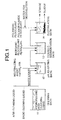
- a waste water treatment shown in Fig. 1 is needed, and, in this treatment, a large amount of resource (waste water treatment agent) is consumed, resulting in a large amount of waste products (waste water and sludge)(see Fig. 2).
- Fig. 1 is an explanatory view illustrating a process for treating the effluent of a cleaning liquid.
- Effluent produced in a cleaning bath 11 is transferred to a pH-adjusting bath 12, and neutralized in this bath by, for example, a 20 % aqueous solution of calcium hydroxide.
- the effluent is transferred to a coagulo-sedimentation bath 13 and subjected to coagulation and sedimentation by a chemical, such as aluminum sulfate, and then, in a flocculation bath 14, is flocculated by a polymeric flocculant, such as a polyacrylamide flocculant, and subjected to sedimentation, followed by discharge in the form of sewage and sludge.
- a polymeric flocculant such as a polyacrylamide flocculant
- a substrate cleaning method and a substrate cleaning apparatus which enable a resource saving and a reduction in waste to be achieved.
- the present invention also provides a substrate cleaning method which is developed for achieving both the uniform and stable cleaning treatment and the reduction in the amount of the cleaning liquid used.
- the present invention provides a substrate cleaning apparatus which is developed for achieving both uniform and stable cleaning treatment and reduction in the amount of the cleaning liquid used.
- a substrate cleaning method and a substrate cleaning apparatus which use an aqueous solution of ammonium fluoride or a mixture of an aqueous solution of ammonium fluoride and hydrofluoric acid as a cleaning liquid is also provided according to the present invention.
- Fig. 1 is an explanatory view illustrating a process for treating an effluent of a cleaning liquid, which is the related art.
- Fig. 2 is a diagram showing a resource (chemicals) required for an effluent treatment for a cleaning liquid, which is the related art.
- Fig. 3 is a graph showing the relationship between time and etching rate with respect to the cleaning liquid.
- Fig. 4 is a graph showing the relationship between the time and the HF concentration of the cleaning liquid.
- Fig. 5 is a diagrammatic view showing an example of a substrate cleaning apparatus, which is a first embodiment of the present invention.
- Fig. 6 is a graph showing the change in the HF concentration by addition of water according to the present invention.
- Fig. 7 is a graph showing the change in the etching rate by addition of water according to the present invention.
- Fig. 8 is a graph showing the state of controlling the etching rate and the HF concentration by addition of water according to the present invention.
- Fig. 9 is a diagrammatic view showing a substrate cleaning apparatus, which is a second embodiment of the present invention.
- Fig. 10 is a diagrammatic view showing an example of a substrate cleaning apparatus in which an aqueous ammonia storage tank is provided, which is a third embodiment of the present invention.
- Fig. 11 is a diagrammatic view showing an example of a substrate cleaning apparatus in which an aqueous ammonia storage tank is provided, which is a fourth embodiment of the present invention.
- the cleaning liquid in the cleaning (or etching) treatment of a substrate using, as a treatment liquid (or a cleaning liquid), an aqueous solution of ammonium fluoride or a mixture of an aqueous solution of ammonium fluoride and hydrofluoric acid, the cleaning liquid is replenished by at least one liquid selected from the group consisting of water, ammonia, aqueous ammonia, and an aqueous solution of ammonium fluoride according to the accumulative time for using the cleaning liquid and the individual component concentrations of the cleaning liquid.
- Fig. 3 shows the relationship between the lapse of time and the etching rate for a thermal oxide film with respect to the mixture of ammonium fluoride and hydrofluoric acid.
- the cleaning liquid has a composition such that the NH 4 F (40 %):HF (50 %) ratio is 400:1, and the temperature of the cleaning liquid is 25°C and the thermal oxide film is comprised of SiO 2 .
- the time is taken as the abscissa and represented by a unit of "days”
- the etching rate for a substrate is taken as the ordinate and represented by a unit of the etching rate per minute, i.e., " ⁇ /min”.
- the etching rate changes with time as follows: after a lapse of 0 day, the etching rate is about 34 ⁇ /min; after a lapse of 11 days, the etching rate is 70 ⁇ /min; and after a lapse of 22 days, the etching rate is 95 ⁇ / min.
- the etching rate for the thermal oxide film remarkably increases with the lapse of time.
- the etching rate changes with time, and there is a very good correlation (proportionality relation) between the etching rate and the time.
- the moisture content and chemical component such as ammonium fluoride (NH 4 F) and hydrogen fluoride (HF)
- NH 4 F ammonium fluoride
- HF hydrogen fluoride
- Fig. 4 shows the change in the HF concentration of the cleaning liquid with the lapse of time.
- the time is taken as the abscissa and represented by a unit of "days”, and ranges from 0 to 25 days.
- the HF concentration of the mixture is taken as the ordinate and represented by a unit of "% by weight (wt%)", and ranges from 0 to 0.6 wt% and is shown in a scale of 0.1 wt%.
- the HF concentration is 0.1 wt%; after a lapse of 11 days, the HF concentration is 0.35 wt%; and after a lapse of 22 days, the HF concentration is 4.7 wt%.
- the HF concentration of the cleaning liquid is required to be kept constant.
- a most effective method is the one in which water that readily evaporates from the cleaning liquid is appropriately added to the cleaning liquid.
- Fig. 5 shows an example of the construction of the substrate cleaning apparatus according to the present invention.
- This substrate cleaning apparatus comprises a substrate treatment bath 21 for storing therein a cleaning liquid comprising, for example, a mixture of ammonium fluoride and hydrofluoric acid, and for subjecting a substrate to cleaning treatment, and a circulation pump 22 for circulating the cleaning liquid which is the overflow back to the substrate treatment bath 21.
- a substrate which is a substance to be treated, is accommodated in a substrate carrier and dipped in the cleaning liquid in the substrate treatment bath 21, and thus performing a cleaning (etching) treatment.
- the characteristic feature of the above apparatus resides in that the substrate treatment'bath 21 is provided with a constant delivery pump 23 and a controller 24, by which feeding water and addition of water through the pump 23 is controlled.
- the HF component concentration of the cleaning liquid increases with the lapse of time at a constant rate, so that the etching rate for the thermal oxide film remarkably increases.
- the HF concentration is controlled by the controller 24 so as to be kept constant by adding water to the substrate treatment bath 21 with the lapse of time by means of the constant delivery pump 23 so that the etching rate is kept substantially constant.
- Fig. 6 shows the change in the HF concentration when water is added.
- the time is taken as the abscissa and represented by a unit of "hours (hrs)", and ranges from 0 to 300 hrs.
- the HF concentration is taken as the ordinate and represented by a unit of "wt%”, and ranges from 2.92 to 3.06 wt%.
- the HF concentration is 2.94 wt%; and after a lapse of 220 hrs, the HF concentration is 3.04 wt%.
- the HF concentration is lowered to 2.95 wt%.
- the HF concentration slightly increases to 2.96 wt%.
- the HF concentration which increases with the lapse of time goes back to the original concentration by addition of water.
- the control of the HF concentration by addition of water leads to the control of the etching rate, and, as shown in Fig. 7, the etching rate is also lowered by the addition of water.
- Fig. 7 is a graph showing the state of controlling the etching rate and HF concentration by addition of water.
- the time is taken as the abscissa and represented by a unit of "hours (hrs)", and ranges from 0 to 250 hours.
- the etching rate is taken as the ordinate and represented by a unit of "nm/min”, and ranges from 65 to 85 nm/min.
- the etching rate is 74 nm/min; after a lapse of 70 hours, the etching rate is 76 nm/min; and after a lapse of 220 hours, the etching rate is 82 nm/min.
- the etching rate is lowered to about 72 nm/min.
- the etching rate and the HF concentration can be kept in a constant range by intermittently adding water.
- FIG. 8 A graph showing the relationship between the etching rate and the hydrofluoric acid concentration when water is intermittently added is illustrated in Fig. 8.
- Fig. 8 shows an example in which water is intermittently added, but the conditions for water addition may be any of continuous addition and intermittent addition. For keeping the concentration constant, the continuous addition is preferred.
- the timing of the addition of water is controlled based on the measurement data, but, as shown in Fig. 9, a concentration measuring unit 35 can be provided to measure the concentration of the cleaning liquid being circulated, so that the addition of water can be controlled based on the concentration data in real time.
- the concentrations of the components (e.g., ammonia, hydrofluoric acid, and water) in the cleaning liquid are individually measured by means of the concentration measuring unit 35, and the measurement result is transmitted to a controller 34 comprised of a computer and a central monitoring unit to determine the addition and calculate the required amount of addition, followed by transmission of an instruction for replenishment to a water feeding line (constant delivery pump 33). Then, whether or not the addition is made in accordance with the instruction is confirmed by a measurement by means of the concentration measuring unit 35.
- a controller 34 comprised of a computer and a central monitoring unit to determine the addition and calculate the required amount of addition, followed by transmission of an instruction for replenishment to a water feeding line (constant delivery pump 33).
- a measurement of an absorbance at a predetermined wavelength, an infrared absorption spectrum, an ultraviolet absorption spectrum, an index of refraction, a specific gravity, a transmittance, or an electric conductivity may be performed and a measuring unit, such as a Karl Fischer moisture titrator or liquid (ion) chromatography may be used.
- Fig. 10 and Fig. 11 show an example in which an aqueous ammonia storage tank 47 or 57 for feeding aqueous ammonia is provided instead of the constant delivery pump 23 or 33 for feeding water in Fig. 5 and Fig. 9, respectively.
- the HF concentration is effectively controlled, so that the etching rate is controlled to be kept constant.
- aqueous ammonia not only aqueous ammonia but also other appropriate aqueous solutions can be used, and further, ammonia gas can also be used.
- ammonia gas can also be used.
- an aqueous solution of ammonium fluoride can be used, and ammonium fluoride can be used in combination with ammonia.
- the etching treatment by the cleaning liquid can be conducted uniformly and stably (namely, the etching rate for an oxide film can be kept constant), so that there is no need to frequently replace the cleaning liquid differing from the conventional cleaning. Therefore, the life time of the cleaning liquid can be prolonged, and the reduction in frequency of the liquid replacement contributes to a reduction in the cleaning liquid consumed (resource saving) and a reduction in the waste water treatment agent required for the waste water treatment of the cleaning liquid (resource saving). Further, the reduction in these chemicals used contributes to a reduction in the amount of sludge and waste water produced upon the waste water treatment (reduction in the amount of waste).
- the present invention not only achieves the uniform and stable substrate treatment but also contributes to resource saving and the reduction in the amount of waste, namely, preservation of the environment.
Landscapes
- Engineering & Computer Science (AREA)
- Physics & Mathematics (AREA)
- Condensed Matter Physics & Semiconductors (AREA)
- General Physics & Mathematics (AREA)
- Manufacturing & Machinery (AREA)
- Computer Hardware Design (AREA)
- Microelectronics & Electronic Packaging (AREA)
- Power Engineering (AREA)
- Cleaning Or Drying Semiconductors (AREA)
- Cleaning By Liquid Or Steam (AREA)
- Weting (AREA)
- Detergent Compositions (AREA)
Abstract
Description
Claims (16)
- A substrate cleaning method for cleaning a substrate using a cleaning liquid comprising at least one selected from the group consisting of an aqueous solution of ammonium fluoride, and a mixture of an aqueous solution of ammonium fluoride and hydrofluoric acid, comprising the steps of:dipping and cleaning the substrate in said cleaning liquid; andadding a replenishing liquid comprising at least one selected from the group consisting of water, ammonia, aqueous ammonia, and an aqueous solution of ammonium fluoride with lapse of time during said cleaning liquid is used.
- The substrate cleaning method according to Claim 1, further comprising the step of measuring characteristics of said cleaning liquid, wherein a kind and an amount of said replenishing liquid are determined in response to a result of the measurement of said cleaning liquid.
- The substrate cleaning method according to Claim 2, wherein, in the measuring step, hydrofluoric acid concentration is measured at a predetermined time interval and water is fed as said replenishing liquid so that a measurement value of said concentration falls within a predetermined range.
- The substrate cleaning method according to Claim 2, wherein said characteristics of said cleaning liquid is measured by at least one measurement selected from the group consisting of measurements of an absorbance at a predetermined wavelength, an infrared absorption spectrum, an ultraviolet absorption spectrum, an index of refraction, a specific gravity, a transmittance, and an electric conductivity, a measurement by means of a moisture titrator, and a measurement by means of liquid (ion) chromatography.
- The substrate cleaning method according to Claim 3, wherein said hydrofluoric acid concentration of said cleaning liquid is measured by at least one measurement selected from the group consisting of measurements of an absorbance at a predetermined wavelength, an infrared absorption spectrum, an ultraviolet absorption spectrum, an index of refraction, a specific gravity, a transmittance, and an electric conductivity, a measurement by means of a moisture titrator, and a measurement by means of liquid (ion) chromatography.
- A substrate cleaning apparatus for cleaning a substrate, comprising:a substrate cleaning bath containing therein a substrate cleaning liquid comprising at least one liquid selected from the group consisting of an aqueous solution of ammonium fluoride, and a mixture of an aqueous solution of ammonium fluoride and hydrofluoric acid; andliquid feeding means for feeding a liquid comprising at least one selected from the group consisting of water, ammonia, aqueous ammonia, and an aqueous solution of ammonium fluoride.
- The substrate cleaning apparatus according to Claim 6, further comprising:measuring means for measuring characteristics of said cleaning liquid in said substrate cleaning bath; andcontrol means for arithmetically processing a signal from said measuring means to control the feeding of the liquid from said liquid feeding means to substrate cleaning bath.
- The substrate cleaning apparatus according to Claim 7, wherein said measuring means comprises means for measuring at least one wavelength characteristic selected from the group consisting of an absorbance at a predetermined wavelength, an infrared absorption spectrum, an ultraviolet absorption spectrum, and an index of refraction.
- The substrate cleaning apparatus according to Claim 7, wherein said measuring means comprises means for measuring at least one physical value selected from the group consisting of a specific gravity and a transmittance.
- The substrate cleaning apparatus according to Claim 7, wherein said measuring means comprises means for measuring an electric conductivity.
- The substrate cleaning apparatus according to Claim 7, wherein said measuring means comprises at least one measurement means selected from the group consisting of a moisture titrator and liquid (ion) chromatography.
- The substrate cleaning apparatus according to Claim 7, wherein said measuring means measures hydrofluoric acid concentration of said cleaning liquid.
- The substrate cleaning apparatus according to Claim 12, wherein said measuring means comprises means for measuring at least one wavelength characteristic selected from the group consisting of an absorbance at a predetermined wavelength, an infrared absorption spectrum, an ultraviolet absorption spectrum, and an index of refraction.
- The substrate cleaning apparatus according to Claim 12, wherein said measuring means comprises means for measuring at least one physical value selected from the group consisting of a specific gravity and a transmittance.
- The substrate cleaning apparatus according to Claim 12, wherein said measuring means comprises means for measuring an electric conductivity.
- The substrate cleaning apparatus according to Claim 12, wherein said measuring means comprises at least one measurement means selected from the group consisting of a moisture titrator and liquid (ion) chromatography.
Applications Claiming Priority (4)
| Application Number | Priority Date | Filing Date | Title |
|---|---|---|---|
| JP2000214974 | 2000-07-14 | ||
| JP2000214974 | 2000-07-14 | ||
| JP2000240134 | 2000-08-08 | ||
| JP2000240134A JP4590700B2 (en) | 2000-07-14 | 2000-08-08 | Substrate cleaning method and substrate cleaning apparatus |
Publications (2)
| Publication Number | Publication Date |
|---|---|
| EP1172844A2 true EP1172844A2 (en) | 2002-01-16 |
| EP1172844A3 EP1172844A3 (en) | 2005-12-14 |
Family
ID=26596094
Family Applications (1)
| Application Number | Title | Priority Date | Filing Date |
|---|---|---|---|
| EP01116941A Withdrawn EP1172844A3 (en) | 2000-07-14 | 2001-07-11 | Substrate cleaning method and substrate cleaning apparatus |
Country Status (5)
| Country | Link |
|---|---|
| US (2) | US20020046757A1 (en) |
| EP (1) | EP1172844A3 (en) |
| JP (1) | JP4590700B2 (en) |
| KR (1) | KR100870255B1 (en) |
| TW (1) | TWI245334B (en) |
Cited By (1)
| Publication number | Priority date | Publication date | Assignee | Title |
|---|---|---|---|---|
| US7659212B2 (en) | 2004-03-22 | 2010-02-09 | Mimasu Semiconductor Industry Co., Ltd. | Process control method in spin etching and spin etching apparatus |
Families Citing this family (25)
| Publication number | Priority date | Publication date | Assignee | Title |
|---|---|---|---|---|
| US20060080632A1 (en) * | 2004-09-30 | 2006-04-13 | Mathstar, Inc. | Integrated circuit layout having rectilinear structure of objects |
| US7098099B1 (en) * | 2005-02-24 | 2006-08-29 | Texas Instruments Incorporated | Semiconductor device having optimized shallow junction geometries and method for fabrication thereof |
| JP2007220980A (en) * | 2006-02-17 | 2007-08-30 | Mitsubishi Electric Corp | Manufacturing method and manufacturing device for solar cell |
| US8511499B2 (en) | 2007-12-18 | 2013-08-20 | Abbott Laboratories | Container |
| EP4219331A1 (en) | 2006-12-27 | 2023-08-02 | Abbott Laboratories | Container |
| US8226775B2 (en) * | 2007-12-14 | 2012-07-24 | Lam Research Corporation | Methods for particle removal by single-phase and two-phase media |
| JP5072892B2 (en) * | 2008-04-03 | 2012-11-14 | 東京エレクトロン株式会社 | Substrate processing apparatus, substrate processing method, and storage medium |
| JP2012119344A (en) * | 2009-03-31 | 2012-06-21 | Sharp Corp | Substrate cleaning apparatus |
| US8469223B2 (en) | 2009-06-05 | 2013-06-25 | Abbott Laboratories | Strength container |
| US8627981B2 (en) | 2009-06-05 | 2014-01-14 | Abbott Laboratories | Container |
| JP5492574B2 (en) * | 2010-01-08 | 2014-05-14 | 東京エレクトロン株式会社 | Substrate cleaning method and substrate cleaning apparatus |
| US20120048303A1 (en) * | 2010-08-26 | 2012-03-01 | Macronix International Co., Ltd. | Process system and cleaning process |
| ES2610243T3 (en) | 2012-04-27 | 2017-04-26 | Abbott Laboratories | Lid attached to a container by a ring |
| USD733320S1 (en) | 2013-04-26 | 2015-06-30 | Abbott Laboratories | Container |
| JP6163434B2 (en) * | 2014-01-16 | 2017-07-12 | 株式会社東芝 | Chemical treatment apparatus and chemical treatment method |
| DE102014103728A1 (en) * | 2014-03-19 | 2015-09-24 | Karl Storz Gmbh & Co. Kg | Automatic detection of the penetration depth and / or the rotational orientation of an invasive instrument |
| US9982156B1 (en) | 2014-04-17 | 2018-05-29 | Lockheed Martin Corporation | Transmissive surfaces and polymeric coatings therefore, for fortification of visible, infrared, and laser optical devices |
| US9616459B1 (en) * | 2014-04-17 | 2017-04-11 | Lockheed Martin Corporation | Polymeric coatings for fortification of visible, infrared, and laser optical devices |
| JP6433730B2 (en) * | 2014-09-08 | 2018-12-05 | 東芝メモリ株式会社 | Semiconductor device manufacturing method and semiconductor manufacturing apparatus |
| EP3015432A1 (en) * | 2014-10-30 | 2016-05-04 | Eliquo Stulz GmbH | Method and device for treating organic mass with sludge return |
| JP6383254B2 (en) * | 2014-11-04 | 2018-08-29 | 株式会社東芝 | Processing apparatus and processing method |
| TWM515418U (en) * | 2015-07-27 | 2016-01-11 | 盟立自動化股份有限公司 | Basin for washing a plate member |
| KR20170029758A (en) * | 2015-09-08 | 2017-03-16 | 삼성전자주식회사 | Semiconductor cleaning process system and methods of manufacturing semiconductor devices |
| TW201713751A (en) * | 2015-10-06 | 2017-04-16 | 聯華電子股份有限公司 | Acid replenishing system and method for acid tank |
| CN115863225B (en) * | 2023-02-27 | 2023-05-26 | 合肥新晶集成电路有限公司 | Method and device for controlling acid supplementation of mixed acid, computer equipment and storage medium |
Citations (7)
| Publication number | Priority date | Publication date | Assignee | Title |
|---|---|---|---|---|
| JPS5946032A (en) * | 1982-09-09 | 1984-03-15 | Hitachi Ltd | Cleaning device |
| JPS60114579A (en) * | 1983-11-25 | 1985-06-21 | Hitachi Ltd | Method for controlling etching solution |
| JPH08334461A (en) * | 1995-06-07 | 1996-12-17 | Nisso Eng Kk | Composition measuring method for buffered hydrofluoric acid for semiconductor wafer etching |
| JPH0922891A (en) * | 1995-07-06 | 1997-01-21 | Fukada Junko | Device and method for wet process |
| US5722441A (en) * | 1993-02-22 | 1998-03-03 | Tokyo Electron Limited | Electronic device process apparatus |
| US5976988A (en) * | 1995-04-26 | 1999-11-02 | Semiconductor Energy Laboratory Co., Ltd. | Etching material and etching method |
| JP2000150447A (en) * | 1998-11-10 | 2000-05-30 | Nec Corp | Method and device for managing concentration of chemical and chemical processing device |
Family Cites Families (14)
| Publication number | Priority date | Publication date | Assignee | Title |
|---|---|---|---|---|
| FR1487060A (en) * | 1965-07-30 | 1967-10-11 | ||
| US3705061A (en) * | 1971-03-19 | 1972-12-05 | Southern California Chem Co In | Continuous redox process for dissolving copper |
| DK374889D0 (en) * | 1989-07-28 | 1989-07-28 | Koege Kemisk Vaerk | PROCEDURE FOR PROCESS MONITORING |
| JP2632262B2 (en) * | 1991-08-20 | 1997-07-23 | 大日本スクリーン製造株式会社 | Method for removing native oxide film in contact hole on silicon wafer |
| US6350425B2 (en) * | 1994-01-07 | 2002-02-26 | Air Liquide America Corporation | On-site generation of ultra-high-purity buffered-HF and ammonium fluoride |
| US5472516A (en) | 1994-04-15 | 1995-12-05 | At&T Corp. | Process and apparatus for semiconductor device fabrication |
| US5903006A (en) * | 1996-05-31 | 1999-05-11 | Norihiro Kiuchi | Liquid concentration detecting apparatus |
| KR100238234B1 (en) | 1997-03-20 | 2000-01-15 | 윤종용 | In-situ cleaning apparatus for semiconductor device and method for cleaning semiconductor device using the same |
| JP3772456B2 (en) * | 1997-04-23 | 2006-05-10 | 三菱電機株式会社 | Solar cell, method for manufacturing the same, and semiconductor manufacturing apparatus |
| EP0989962A4 (en) | 1997-06-13 | 2005-03-09 | Mattson Technology Ip Inc | Methods for treating semiconductor wafers |
| US6261845B1 (en) | 1999-02-25 | 2001-07-17 | Cfmt, Inc. | Methods and systems for determining chemical concentrations and controlling the processing of semiconductor substrates |
| EP1149411A1 (en) * | 1999-11-26 | 2001-10-31 | Koninklijke Philips Electronics N.V. | Method and apparatus for wet-etching semiconductor wafers |
| US6589884B1 (en) * | 2000-08-31 | 2003-07-08 | Micron Technology, Inc. | Method of forming an inset in a tungsten silicide layer in a transistor gate stack |
| US6767877B2 (en) * | 2001-04-06 | 2004-07-27 | Akrion, Llc | Method and system for chemical injection in silicon wafer processing |
-
2000
- 2000-08-08 JP JP2000240134A patent/JP4590700B2/en not_active Expired - Fee Related
-
2001
- 2001-07-03 TW TW090116257A patent/TWI245334B/en not_active IP Right Cessation
- 2001-07-11 EP EP01116941A patent/EP1172844A3/en not_active Withdrawn
- 2001-07-13 US US09/905,662 patent/US20020046757A1/en not_active Abandoned
- 2001-07-13 KR KR1020010042362A patent/KR100870255B1/en not_active IP Right Cessation
-
2004
- 2004-09-09 US US10/937,014 patent/US7255749B2/en not_active Expired - Fee Related
Patent Citations (7)
| Publication number | Priority date | Publication date | Assignee | Title |
|---|---|---|---|---|
| JPS5946032A (en) * | 1982-09-09 | 1984-03-15 | Hitachi Ltd | Cleaning device |
| JPS60114579A (en) * | 1983-11-25 | 1985-06-21 | Hitachi Ltd | Method for controlling etching solution |
| US5722441A (en) * | 1993-02-22 | 1998-03-03 | Tokyo Electron Limited | Electronic device process apparatus |
| US5976988A (en) * | 1995-04-26 | 1999-11-02 | Semiconductor Energy Laboratory Co., Ltd. | Etching material and etching method |
| JPH08334461A (en) * | 1995-06-07 | 1996-12-17 | Nisso Eng Kk | Composition measuring method for buffered hydrofluoric acid for semiconductor wafer etching |
| JPH0922891A (en) * | 1995-07-06 | 1997-01-21 | Fukada Junko | Device and method for wet process |
| JP2000150447A (en) * | 1998-11-10 | 2000-05-30 | Nec Corp | Method and device for managing concentration of chemical and chemical processing device |
Non-Patent Citations (6)
| Title |
|---|
| KASHKOUSH I ET AL: "IN-SITU CHEMICAL CONCENTRATION CONTROL FOR WAFER WET CLEANING" May 1998 (1998-05), JOURNAL OF THE IES, MOUNT PROSPECT, IL, US, PAGE(S) 24-30 , XP000957413 ISSN: 1052-2883 * the whole document * * |
| PATENT ABSTRACTS OF JAPAN vol. 008, no. 135 (E-252), 22 June 1984 (1984-06-22) -& JP 59 046032 A (HITACHI SEISAKUSHO KK), 15 March 1984 (1984-03-15) * |
| PATENT ABSTRACTS OF JAPAN vol. 009, no. 267 (C-310), 24 October 1985 (1985-10-24) -& JP 60 114579 A (HITACHI SEISAKUSHO KK), 21 June 1985 (1985-06-21) * |
| PATENT ABSTRACTS OF JAPAN vol. 1997, no. 04, 30 April 1997 (1997-04-30) -& JP 08 334461 A (NISSO ENG KK), 17 December 1996 (1996-12-17) * |
| PATENT ABSTRACTS OF JAPAN vol. 1997, no. 05, 30 May 1997 (1997-05-30) -& JP 09 022891 A (FUKADA JUNKO), 21 January 1997 (1997-01-21) * |
| PATENT ABSTRACTS OF JAPAN vol. 2000, no. 08, 6 October 2000 (2000-10-06) -& JP 2000 150447 A (NEC CORP), 30 May 2000 (2000-05-30) * |
Cited By (1)
| Publication number | Priority date | Publication date | Assignee | Title |
|---|---|---|---|---|
| US7659212B2 (en) | 2004-03-22 | 2010-02-09 | Mimasu Semiconductor Industry Co., Ltd. | Process control method in spin etching and spin etching apparatus |
Also Published As
| Publication number | Publication date |
|---|---|
| US7255749B2 (en) | 2007-08-14 |
| EP1172844A3 (en) | 2005-12-14 |
| KR100870255B1 (en) | 2008-11-25 |
| US20050022845A1 (en) | 2005-02-03 |
| JP4590700B2 (en) | 2010-12-01 |
| KR20020007210A (en) | 2002-01-26 |
| TWI245334B (en) | 2005-12-11 |
| JP2002086084A (en) | 2002-03-26 |
| US20020046757A1 (en) | 2002-04-25 |
Similar Documents
| Publication | Publication Date | Title |
|---|---|---|
| US7255749B2 (en) | Substrate cleaning method and substrate cleaning apparatus | |
| US7101517B2 (en) | Processing solution preparation and supply method and apparatus | |
| KR970072163A (en) | Semiconductor Nitride Etching Equipment | |
| US6286526B1 (en) | Method for treatment of semiconductor substrate with chemical solution and apparatus used for said treatment | |
| TW508626B (en) | Arrangement and method for detecting the end of life of an aqueous bath utilized in semiconductor processing | |
| JPH0922891A (en) | Device and method for wet process | |
| JP2000150447A (en) | Method and device for managing concentration of chemical and chemical processing device | |
| KR100664774B1 (en) | Method and apparatus for wet-etching semiconductor wafers | |
| KR950015629A (en) | Silicon substrate cleaning method | |
| JP4419315B2 (en) | Substrate cleaning method and substrate cleaning apparatus | |
| JP2002143790A (en) | Method and apparatus for cleaning substrate | |
| JP4604320B2 (en) | Substrate cleaning method and substrate cleaning apparatus | |
| JP3430611B2 (en) | Etching apparatus and treatment method for concentrated phosphoric acid solution | |
| JP2002143791A (en) | Method and apparatus for cleaning substrate | |
| KR100524399B1 (en) | Apparatus for manufacturing mixed cleaning solution and method of manufacturing mixed cleaning solution using the same | |
| JP2003049285A (en) | Etching method, quantitative analysis method for etching solution and method for recovering phosphoric acid from etching solution | |
| JP2003100696A (en) | Automatic concentration control device | |
| JPH0524660B2 (en) | ||
| JPH111781A (en) | Method and apparatus for managing etchant | |
| JP5934083B2 (en) | Waste water treatment apparatus and treatment method containing nitric acid and nitrous acid | |
| JPH05259141A (en) | Cleaning method for semiconductor device | |
| JP2000042571A (en) | Fluorine-containing waste water treating device | |
| JPH07306146A (en) | Method and instrument for measuring concentration of solution and cleaning device | |
| JP2010125370A (en) | Control method for reducing volume of surplus sludge | |
| JP2000290787A (en) | Method for suppressing gaseous nox by hydrogen peroxide |
Legal Events
| Date | Code | Title | Description |
|---|---|---|---|
| PUAI | Public reference made under article 153(3) epc to a published international application that has entered the european phase |
Free format text: ORIGINAL CODE: 0009012 |
|
| AK | Designated contracting states |
Kind code of ref document: A2 Designated state(s): AT BE CH CY DE DK ES FI FR GB GR IE IT LI LU MC NL PT SE TR |
|
| AX | Request for extension of the european patent |
Free format text: AL;LT;LV;MK;RO;SI |
|
| PUAL | Search report despatched |
Free format text: ORIGINAL CODE: 0009013 |
|
| AK | Designated contracting states |
Kind code of ref document: A3 Designated state(s): AT BE CH CY DE DK ES FI FR GB GR IE IT LI LU MC NL PT SE TR |
|
| AX | Request for extension of the european patent |
Extension state: AL LT LV MK RO SI |
|
| RIC1 | Information provided on ipc code assigned before grant |
Ipc: 7H 01L 21/306 B Ipc: 7H 01L 21/00 A |
|
| 17P | Request for examination filed |
Effective date: 20060519 |
|
| AKX | Designation fees paid |
Designated state(s): DE FR GB |
|
| 17Q | First examination report despatched |
Effective date: 20060901 |
|
| STAA | Information on the status of an ep patent application or granted ep patent |
Free format text: STATUS: THE APPLICATION HAS BEEN WITHDRAWN |
|
| 18W | Application withdrawn |
Effective date: 20080307 |