EP1168313A2 - Disque d'enregistrement à plusieurs couches - Google Patents
Disque d'enregistrement à plusieurs couches Download PDFInfo
- Publication number
- EP1168313A2 EP1168313A2 EP01119499A EP01119499A EP1168313A2 EP 1168313 A2 EP1168313 A2 EP 1168313A2 EP 01119499 A EP01119499 A EP 01119499A EP 01119499 A EP01119499 A EP 01119499A EP 1168313 A2 EP1168313 A2 EP 1168313A2
- Authority
- EP
- European Patent Office
- Prior art keywords
- data recording
- light
- read
- data
- recording surface
- Prior art date
- Legal status (The legal status is an assumption and is not a legal conclusion. Google has not performed a legal analysis and makes no representation as to the accuracy of the status listed.)
- Withdrawn
Links
- 239000000463 material Substances 0.000 claims description 25
- 239000004973 liquid crystal related substance Substances 0.000 claims description 9
- 230000001678 irradiating effect Effects 0.000 claims description 7
- 230000004044 response Effects 0.000 claims description 6
- 238000006243 chemical reaction Methods 0.000 claims 1
- 230000008859 change Effects 0.000 abstract description 6
- 239000010410 layer Substances 0.000 description 93
- 230000003287 optical effect Effects 0.000 description 25
- 230000014509 gene expression Effects 0.000 description 24
- 239000000758 substrate Substances 0.000 description 23
- 239000011347 resin Substances 0.000 description 22
- 229920005989 resin Polymers 0.000 description 22
- 230000004075 alteration Effects 0.000 description 19
- 230000005540 biological transmission Effects 0.000 description 16
- 230000002285 radioactive effect Effects 0.000 description 13
- 238000000034 method Methods 0.000 description 5
- PXHVJJICTQNCMI-UHFFFAOYSA-N Nickel Chemical compound [Ni] PXHVJJICTQNCMI-UHFFFAOYSA-N 0.000 description 4
- 238000010586 diagram Methods 0.000 description 4
- 238000004519 manufacturing process Methods 0.000 description 3
- 238000013518 transcription Methods 0.000 description 3
- 230000035897 transcription Effects 0.000 description 3
- NCGICGYLBXGBGN-UHFFFAOYSA-N 3-morpholin-4-yl-1-oxa-3-azonia-2-azanidacyclopent-3-en-5-imine;hydrochloride Chemical compound Cl.[N-]1OC(=N)C=[N+]1N1CCOCC1 NCGICGYLBXGBGN-UHFFFAOYSA-N 0.000 description 2
- XUIMIQQOPSSXEZ-UHFFFAOYSA-N Silicon Chemical compound [Si] XUIMIQQOPSSXEZ-UHFFFAOYSA-N 0.000 description 2
- 239000004411 aluminium Substances 0.000 description 2
- XAGFODPZIPBFFR-UHFFFAOYSA-N aluminium Chemical compound [Al] XAGFODPZIPBFFR-UHFFFAOYSA-N 0.000 description 2
- 229910052782 aluminium Inorganic materials 0.000 description 2
- 230000003028 elevating effect Effects 0.000 description 2
- 239000011521 glass Substances 0.000 description 2
- 238000001746 injection moulding Methods 0.000 description 2
- 239000007791 liquid phase Substances 0.000 description 2
- 229910052759 nickel Inorganic materials 0.000 description 2
- 239000004417 polycarbonate Substances 0.000 description 2
- 230000008569 process Effects 0.000 description 2
- 239000004065 semiconductor Substances 0.000 description 2
- 229910052710 silicon Inorganic materials 0.000 description 2
- 239000010703 silicon Substances 0.000 description 2
- 238000001771 vacuum deposition Methods 0.000 description 2
- 235000010627 Phaseolus vulgaris Nutrition 0.000 description 1
- 244000046052 Phaseolus vulgaris Species 0.000 description 1
- 230000015572 biosynthetic process Effects 0.000 description 1
- 238000005520 cutting process Methods 0.000 description 1
- 238000001514 detection method Methods 0.000 description 1
- 238000005530 etching Methods 0.000 description 1
- 239000005357 flat glass Substances 0.000 description 1
- 238000010030 laminating Methods 0.000 description 1
- 238000000465 moulding Methods 0.000 description 1
- 239000005022 packaging material Substances 0.000 description 1
- 238000005424 photoluminescence Methods 0.000 description 1
- 239000004033 plastic Substances 0.000 description 1
- 229920003023 plastic Polymers 0.000 description 1
- 229920003229 poly(methyl methacrylate) Polymers 0.000 description 1
- 229920000515 polycarbonate Polymers 0.000 description 1
- 239000004926 polymethyl methacrylate Substances 0.000 description 1
- 238000005070 sampling Methods 0.000 description 1
- 238000007493 shaping process Methods 0.000 description 1
- 238000004088 simulation Methods 0.000 description 1
- 239000002356 single layer Substances 0.000 description 1
- 238000005549 size reduction Methods 0.000 description 1
- 238000003860 storage Methods 0.000 description 1
Images


Classifications
-
- G—PHYSICS
- G11—INFORMATION STORAGE
- G11B—INFORMATION STORAGE BASED ON RELATIVE MOVEMENT BETWEEN RECORD CARRIER AND TRANSDUCER
- G11B7/00—Recording or reproducing by optical means, e.g. recording using a thermal beam of optical radiation by modifying optical properties or the physical structure, reproducing using an optical beam at lower power by sensing optical properties; Record carriers therefor
- G11B7/24—Record carriers characterised by shape, structure or physical properties, or by the selection of the material
- G11B7/241—Record carriers characterised by shape, structure or physical properties, or by the selection of the material characterised by the selection of the material
- G11B7/252—Record carriers characterised by shape, structure or physical properties, or by the selection of the material characterised by the selection of the material of layers other than recording layers
- G11B7/258—Record carriers characterised by shape, structure or physical properties, or by the selection of the material characterised by the selection of the material of layers other than recording layers of reflective layers
-
- G—PHYSICS
- G11—INFORMATION STORAGE
- G11B—INFORMATION STORAGE BASED ON RELATIVE MOVEMENT BETWEEN RECORD CARRIER AND TRANSDUCER
- G11B7/00—Recording or reproducing by optical means, e.g. recording using a thermal beam of optical radiation by modifying optical properties or the physical structure, reproducing using an optical beam at lower power by sensing optical properties; Record carriers therefor
- G11B7/004—Recording, reproducing or erasing methods; Read, write or erase circuits therefor
- G11B7/005—Reproducing
-
- G—PHYSICS
- G11—INFORMATION STORAGE
- G11B—INFORMATION STORAGE BASED ON RELATIVE MOVEMENT BETWEEN RECORD CARRIER AND TRANSDUCER
- G11B7/00—Recording or reproducing by optical means, e.g. recording using a thermal beam of optical radiation by modifying optical properties or the physical structure, reproducing using an optical beam at lower power by sensing optical properties; Record carriers therefor
- G11B7/007—Arrangement of the information on the record carrier, e.g. form of tracks, actual track shape, e.g. wobbled, or cross-section, e.g. v-shaped; Sequential information structures, e.g. sectoring or header formats within a track
- G11B7/0079—Zoned data area, e.g. having different data structures or formats for the user data within data layer, Zone Constant Linear Velocity [ZCLV], Zone Constant Angular Velocity [ZCAV], carriers with RAM and ROM areas
-
- G—PHYSICS
- G11—INFORMATION STORAGE
- G11B—INFORMATION STORAGE BASED ON RELATIVE MOVEMENT BETWEEN RECORD CARRIER AND TRANSDUCER
- G11B7/00—Recording or reproducing by optical means, e.g. recording using a thermal beam of optical radiation by modifying optical properties or the physical structure, reproducing using an optical beam at lower power by sensing optical properties; Record carriers therefor
- G11B7/08—Disposition or mounting of heads or light sources relatively to record carriers
- G11B7/085—Disposition or mounting of heads or light sources relatively to record carriers with provision for moving the light beam into, or out of, its operative position or across tracks, otherwise than during the transducing operation, e.g. for adjustment or preliminary positioning or track change or selection
- G11B7/08505—Methods for track change, selection or preliminary positioning by moving the head
- G11B7/08511—Methods for track change, selection or preliminary positioning by moving the head with focus pull-in only
-
- G—PHYSICS
- G11—INFORMATION STORAGE
- G11B—INFORMATION STORAGE BASED ON RELATIVE MOVEMENT BETWEEN RECORD CARRIER AND TRANSDUCER
- G11B7/00—Recording or reproducing by optical means, e.g. recording using a thermal beam of optical radiation by modifying optical properties or the physical structure, reproducing using an optical beam at lower power by sensing optical properties; Record carriers therefor
- G11B7/24—Record carriers characterised by shape, structure or physical properties, or by the selection of the material
- G11B7/2403—Layers; Shape, structure or physical properties thereof
- G11B7/24035—Recording layers
- G11B7/24038—Multiple laminated recording layers
-
- G—PHYSICS
- G11—INFORMATION STORAGE
- G11B—INFORMATION STORAGE BASED ON RELATIVE MOVEMENT BETWEEN RECORD CARRIER AND TRANSDUCER
- G11B7/00—Recording or reproducing by optical means, e.g. recording using a thermal beam of optical radiation by modifying optical properties or the physical structure, reproducing using an optical beam at lower power by sensing optical properties; Record carriers therefor
- G11B7/24—Record carriers characterised by shape, structure or physical properties, or by the selection of the material
- G11B7/2407—Tracks or pits; Shape, structure or physical properties thereof
- G11B7/24073—Tracks
- G11B7/24082—Meandering
-
- G—PHYSICS
- G11—INFORMATION STORAGE
- G11B—INFORMATION STORAGE BASED ON RELATIVE MOVEMENT BETWEEN RECORD CARRIER AND TRANSDUCER
- G11B7/00—Recording or reproducing by optical means, e.g. recording using a thermal beam of optical radiation by modifying optical properties or the physical structure, reproducing using an optical beam at lower power by sensing optical properties; Record carriers therefor
- G11B7/24—Record carriers characterised by shape, structure or physical properties, or by the selection of the material
- G11B7/241—Record carriers characterised by shape, structure or physical properties, or by the selection of the material characterised by the selection of the material
- G11B7/242—Record carriers characterised by shape, structure or physical properties, or by the selection of the material characterised by the selection of the material of recording layers
- G11B7/243—Record carriers characterised by shape, structure or physical properties, or by the selection of the material characterised by the selection of the material of recording layers comprising inorganic materials only, e.g. ablative layers
-
- G—PHYSICS
- G11—INFORMATION STORAGE
- G11B—INFORMATION STORAGE BASED ON RELATIVE MOVEMENT BETWEEN RECORD CARRIER AND TRANSDUCER
- G11B7/00—Recording or reproducing by optical means, e.g. recording using a thermal beam of optical radiation by modifying optical properties or the physical structure, reproducing using an optical beam at lower power by sensing optical properties; Record carriers therefor
- G11B7/24—Record carriers characterised by shape, structure or physical properties, or by the selection of the material
- G11B7/241—Record carriers characterised by shape, structure or physical properties, or by the selection of the material characterised by the selection of the material
- G11B7/242—Record carriers characterised by shape, structure or physical properties, or by the selection of the material characterised by the selection of the material of recording layers
- G11B7/244—Record carriers characterised by shape, structure or physical properties, or by the selection of the material characterised by the selection of the material of recording layers comprising organic materials only
- G11B7/25—Record carriers characterised by shape, structure or physical properties, or by the selection of the material characterised by the selection of the material of recording layers comprising organic materials only containing liquid crystals
-
- G—PHYSICS
- G11—INFORMATION STORAGE
- G11B—INFORMATION STORAGE BASED ON RELATIVE MOVEMENT BETWEEN RECORD CARRIER AND TRANSDUCER
- G11B7/00—Recording or reproducing by optical means, e.g. recording using a thermal beam of optical radiation by modifying optical properties or the physical structure, reproducing using an optical beam at lower power by sensing optical properties; Record carriers therefor
- G11B7/24—Record carriers characterised by shape, structure or physical properties, or by the selection of the material
- G11B7/241—Record carriers characterised by shape, structure or physical properties, or by the selection of the material characterised by the selection of the material
- G11B7/252—Record carriers characterised by shape, structure or physical properties, or by the selection of the material characterised by the selection of the material of layers other than recording layers
- G11B7/253—Record carriers characterised by shape, structure or physical properties, or by the selection of the material characterised by the selection of the material of layers other than recording layers of substrates
-
- G—PHYSICS
- G11—INFORMATION STORAGE
- G11B—INFORMATION STORAGE BASED ON RELATIVE MOVEMENT BETWEEN RECORD CARRIER AND TRANSDUCER
- G11B7/00—Recording or reproducing by optical means, e.g. recording using a thermal beam of optical radiation by modifying optical properties or the physical structure, reproducing using an optical beam at lower power by sensing optical properties; Record carriers therefor
- G11B7/24—Record carriers characterised by shape, structure or physical properties, or by the selection of the material
- G11B7/26—Apparatus or processes specially adapted for the manufacture of record carriers
-
- G—PHYSICS
- G11—INFORMATION STORAGE
- G11B—INFORMATION STORAGE BASED ON RELATIVE MOVEMENT BETWEEN RECORD CARRIER AND TRANSDUCER
- G11B7/00—Recording or reproducing by optical means, e.g. recording using a thermal beam of optical radiation by modifying optical properties or the physical structure, reproducing using an optical beam at lower power by sensing optical properties; Record carriers therefor
- G11B2007/0003—Recording, reproducing or erasing systems characterised by the structure or type of the carrier
- G11B2007/0009—Recording, reproducing or erasing systems characterised by the structure or type of the carrier for carriers having data stored in three dimensions, e.g. volume storage
- G11B2007/0013—Recording, reproducing or erasing systems characterised by the structure or type of the carrier for carriers having data stored in three dimensions, e.g. volume storage for carriers having multiple discrete layers
-
- G—PHYSICS
- G11—INFORMATION STORAGE
- G11B—INFORMATION STORAGE BASED ON RELATIVE MOVEMENT BETWEEN RECORD CARRIER AND TRANSDUCER
- G11B7/00—Recording or reproducing by optical means, e.g. recording using a thermal beam of optical radiation by modifying optical properties or the physical structure, reproducing using an optical beam at lower power by sensing optical properties; Record carriers therefor
- G11B7/004—Recording, reproducing or erasing methods; Read, write or erase circuits therefor
- G11B7/0045—Recording
-
- G—PHYSICS
- G11—INFORMATION STORAGE
- G11B—INFORMATION STORAGE BASED ON RELATIVE MOVEMENT BETWEEN RECORD CARRIER AND TRANSDUCER
- G11B7/00—Recording or reproducing by optical means, e.g. recording using a thermal beam of optical radiation by modifying optical properties or the physical structure, reproducing using an optical beam at lower power by sensing optical properties; Record carriers therefor
- G11B7/007—Arrangement of the information on the record carrier, e.g. form of tracks, actual track shape, e.g. wobbled, or cross-section, e.g. v-shaped; Sequential information structures, e.g. sectoring or header formats within a track
- G11B7/013—Arrangement of the information on the record carrier, e.g. form of tracks, actual track shape, e.g. wobbled, or cross-section, e.g. v-shaped; Sequential information structures, e.g. sectoring or header formats within a track for discrete information, i.e. where each information unit is stored in a distinct discrete location, e.g. digital information formats within a data block or sector
-
- G—PHYSICS
- G11—INFORMATION STORAGE
- G11B—INFORMATION STORAGE BASED ON RELATIVE MOVEMENT BETWEEN RECORD CARRIER AND TRANSDUCER
- G11B7/00—Recording or reproducing by optical means, e.g. recording using a thermal beam of optical radiation by modifying optical properties or the physical structure, reproducing using an optical beam at lower power by sensing optical properties; Record carriers therefor
- G11B7/24—Record carriers characterised by shape, structure or physical properties, or by the selection of the material
- G11B7/241—Record carriers characterised by shape, structure or physical properties, or by the selection of the material characterised by the selection of the material
- G11B7/252—Record carriers characterised by shape, structure or physical properties, or by the selection of the material characterised by the selection of the material of layers other than recording layers
- G11B7/253—Record carriers characterised by shape, structure or physical properties, or by the selection of the material characterised by the selection of the material of layers other than recording layers of substrates
- G11B7/2531—Record carriers characterised by shape, structure or physical properties, or by the selection of the material characterised by the selection of the material of layers other than recording layers of substrates comprising glass
-
- G—PHYSICS
- G11—INFORMATION STORAGE
- G11B—INFORMATION STORAGE BASED ON RELATIVE MOVEMENT BETWEEN RECORD CARRIER AND TRANSDUCER
- G11B7/00—Recording or reproducing by optical means, e.g. recording using a thermal beam of optical radiation by modifying optical properties or the physical structure, reproducing using an optical beam at lower power by sensing optical properties; Record carriers therefor
- G11B7/24—Record carriers characterised by shape, structure or physical properties, or by the selection of the material
- G11B7/241—Record carriers characterised by shape, structure or physical properties, or by the selection of the material characterised by the selection of the material
- G11B7/252—Record carriers characterised by shape, structure or physical properties, or by the selection of the material characterised by the selection of the material of layers other than recording layers
- G11B7/253—Record carriers characterised by shape, structure or physical properties, or by the selection of the material characterised by the selection of the material of layers other than recording layers of substrates
- G11B7/2533—Record carriers characterised by shape, structure or physical properties, or by the selection of the material characterised by the selection of the material of layers other than recording layers of substrates comprising resins
- G11B7/2534—Record carriers characterised by shape, structure or physical properties, or by the selection of the material characterised by the selection of the material of layers other than recording layers of substrates comprising resins polycarbonates [PC]
-
- G—PHYSICS
- G11—INFORMATION STORAGE
- G11B—INFORMATION STORAGE BASED ON RELATIVE MOVEMENT BETWEEN RECORD CARRIER AND TRANSDUCER
- G11B7/00—Recording or reproducing by optical means, e.g. recording using a thermal beam of optical radiation by modifying optical properties or the physical structure, reproducing using an optical beam at lower power by sensing optical properties; Record carriers therefor
- G11B7/24—Record carriers characterised by shape, structure or physical properties, or by the selection of the material
- G11B7/241—Record carriers characterised by shape, structure or physical properties, or by the selection of the material characterised by the selection of the material
- G11B7/252—Record carriers characterised by shape, structure or physical properties, or by the selection of the material characterised by the selection of the material of layers other than recording layers
- G11B7/254—Record carriers characterised by shape, structure or physical properties, or by the selection of the material characterised by the selection of the material of layers other than recording layers of protective topcoat layers
- G11B7/2542—Record carriers characterised by shape, structure or physical properties, or by the selection of the material characterised by the selection of the material of layers other than recording layers of protective topcoat layers consisting essentially of organic resins
-
- G—PHYSICS
- G11—INFORMATION STORAGE
- G11B—INFORMATION STORAGE BASED ON RELATIVE MOVEMENT BETWEEN RECORD CARRIER AND TRANSDUCER
- G11B7/00—Recording or reproducing by optical means, e.g. recording using a thermal beam of optical radiation by modifying optical properties or the physical structure, reproducing using an optical beam at lower power by sensing optical properties; Record carriers therefor
- G11B7/24—Record carriers characterised by shape, structure or physical properties, or by the selection of the material
- G11B7/241—Record carriers characterised by shape, structure or physical properties, or by the selection of the material characterised by the selection of the material
- G11B7/252—Record carriers characterised by shape, structure or physical properties, or by the selection of the material characterised by the selection of the material of layers other than recording layers
- G11B7/258—Record carriers characterised by shape, structure or physical properties, or by the selection of the material characterised by the selection of the material of layers other than recording layers of reflective layers
- G11B7/2585—Record carriers characterised by shape, structure or physical properties, or by the selection of the material characterised by the selection of the material of layers other than recording layers of reflective layers based on aluminium
Definitions
- the present invention relates to a disk-shaped recording medium, and more particularly to a multi-layered disk comprising a plurality of laminated data recording layers. Also the present invention relates to a system for recording signal in each of the data recording layers described above, and a system for reproducing signals recorded in each of the data recording layers.
- High density storage of data in optical disks has been mainly realized by making higher a recording density in a recording surface of the disks. Also there have been made various types of effort for the same purpose by making shorter a track pitch or elevating a recording density in the linear velocity direction in scan for recording and reading in combination with efforts for making shorter a wavelength of light beam for recording emitted from a light source and signal processing in the reproducing system.
- a wavelength of a light beam emitted from a light source can be made only in a ultraviolet region, and also pit size reduction is allowable only on the condition that the transcription to a disk can be executed in cutting, and it can be considered that the efforts for elevating a recording density in a two-dimensional region will reach a limit in the future.
- a multi-layered disk formed by laminating data recording layers has been disclosed in Japanese Patent Laid-Open Publication No. H2-223030 (Japanese Patent Application No. H1-20999) or others to realize data recording at a higher density in a three-dimensional region, namely in the direction of thickness of a disk.
- the present invention was made in the light of the circumstances described above, and it is an object of the present invention to further elevate a density of recorded data and to provide a multi-layered disk for smoothly recording signals and reproducing the recorded signals and a recording system as well as a reproducing system using the same.
- the invention provides a multi-layered recording disc in which a recording or reading direction of one of the data surfaces is contrary to that of another of the data surfaces.
- the invention also provides a reproducing system for reading the multi-layered disk, wherein reading is started in response to a start instruction from either an inner side position or an outer side position in one of the data recording surfaces, after the final signal in the data recording surface is read, an operation for focusing a read light on other data recording surface is executed at the other position, and reading is restarted from the other position in the other data recording surface.
- the multi-layered recording disk according to the present invention is a multi-layered disk in which a plurality of data recording surfaces are laminated, and is characterized in that data signals recorded in each of the data recording surfaces in a band where, against a reproduction level obtained when a read beam is on focus to one of the data recording surfaces, a reproduction level obtained when the read beam is defocusing to other one of the data recording surface is 1/N (N is a real number larger than 1), and a distance t between each of the data recording surfaces, numerical aperture NA of an objective lens guiding the read beam onto any of the data recording surfaces, a wavelength ⁇ of the read beam, an equivalent refractive index n between each of the data recording surfaces, and a number i of the laminated data recording surfaces satisfies the following relation: 1.4 n ⁇ /(NA) 2 ⁇ t ⁇ 7.5 n 3 ⁇ / ⁇ (n 2 -1) (NA) 4 (i-1) ⁇ With the multi-layered recording disk according to the present invention, against a reproduction level obtained when
- Fig. 1 is a cross-sectional view illustrating structure of a ROM type optical disk having two light reflection layers each functioning as a data recording layer in an embodiment of the present invention
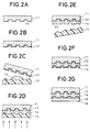
- Figs. 2A to 2G are cross-sectional views each illustrating a disk in each process for explanation of a method of manufacturing an optical disk shown in Fig. 1;
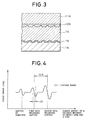
- Fig. 3 is a cross-sectional view illustrating a structure of a ROM type optical disk having a structure equivalent to that of the optical disk shown in Fig. 1;
- Fig. 4 is a graph showing a focus error level against a change amount of a distance between an objective lens and a disk in a focusing operation to the optical disk shown in Fig. 1 and Fig. 3;
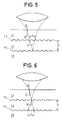
- Fig. 5 is a geometrical view showing a size of a light beam on a first data recording surface when a light beam is focusing onto a second data recording surface in the optical disk shown in Fig. 1 and Fig. 3;
- Fig. 6 is a geometrical view showing a size of a light beam on the second data recording surface when the light beam is focusing onto the first data recording surface in the optical disk shown in Fig. 1 and Fig. 3;
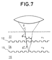
- Fig. 7 is a geometrical view showing a size of a light beam in the first data recording surface when the light beam is focusing on the second data recording surface in the optical disk shown in Fig. 1 and Fig. 3 when a refractive index between a transparent substrate and a first data recording surface is not equal to that between the first data recording surface and a second data recording surface;
- Fig. 8 is a graph showing the MTF characteristics of defocus and on-focus states of a light beam in the optical disk shown in Fig. 1 and Fig. 3;
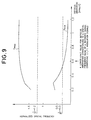
- Fig. 9 is a graph showing a maximum value and a minimum value of a normalized spacial frequency to a defocus aberration in a case where a reproduction level when defocusing is less than 1/N of a reproduction level when on-focusing;
- Fig. 10 is a simplified cross-sectional view of a disk having i pieces of data recording surfaces for explanation of an operation for guiding an upper limit value of a distance between data recording surfaces in an optical disk according to the present invention as well as for explanation of a difference in light energy density of a read light in each data recording surface;
- Fig. 11 is a chart illustrating an example of an operation for computing upper and lower limit values of a distance between data recording surfaces in the optical disk according to the present invention
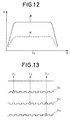
- Fig. 12 is a graph showing the refractive index characteristics of one data recording surface closer to a side where a read beam comes in and other data recording surface;
- Fig. 13 is a simplified cross-sectional view of a disk illustrating an operating for reading the first and third data recording surfaces with read beams each having a different wavelength respectively;
- Fig. 14 is a graph showing the refractive index characteristics of each data recording surface in the optical disk shown in Fig. 13;
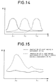
- Fig. 15 is a graph illustrating the refractive index characteristics of a photochromic material
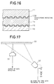
- Fig. 16 is a cross-sectional view of a multi-layered recording disk according to an embodiment of the present invention.
- Fig. 17 is a block diagram illustrating configuration of a reproducing system according to an embodiment of the present invention for reproducing recorded data in the disk shown in Fig. 16;
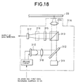
- Fig. 18 is a block diagram illustrating configuration of a reproducing system according to another embodiment of the present invention for reproducing recorded data in the disk shown in Fig. 16;
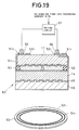
- Fig. 19 is a cross-sectional view as well as an appearance view of a multi-layered recording disk having a liquid crystal layer according to an embodiment of the present invention.
- Fig. 20 is a simulated view for explanation of a problem concerning a spiral direction of a recording track in each data recording surface in a multi-layered recording disk;
- Fig. 21 is a simulated view for explanation of a spiral direction of a recording track in each data recording surface in a multi-layered recording disk according to the present invention.
- Fig. 22 is a simulated view illustrating an example of recording state of TOC data in the multi-layered recording disk according to the present invention.
- Fig. 23 is a simulated view illustrating another example of recording state of TOC data in the
- Fig. 24 is a block diagram illustrating configuration of a reproducing system for reading recorded signals in the multi-layered disk according to the present invention.
- a ROM type optical disk having two light reflecting layers as data recording layers as shown in Fig. 1 are manufactured as described below.
- a transparent substrate 11 carrying a first recording pit P1 is prepared.
- the transparent substrate 11 is obtained by means of injection-molding of transparent resins such as PMMA (polymethaacrylate), or PC (Polycarbonate) using as a molding die a nickel stamper (not shown) with a first recording pit P1 arrayed in a screw or coaxial formed on the surface thereof.
- transparent resins such as PMMA (polymethaacrylate), or PC (Polycarbonate)
- a nickel stamper not shown
- arrayed pits on the nickel stamper are transcribed as embossed pits, namely first pits P1 onto the substrate 11.
- the transparent substrate 11 may be manufactured by etching a glass substrate to form embossed pits thereon.
- a first reflecting layer 12 is formed on the transparent substrate 11 as described above.
- a transparent stamper 13 is prepared, and is mounted on a transcription device.
- the transparent stamper 13 is made from glass or plastics which allows transmission of a light having a wavelength band required for curing the radioactive ray curing type resins (ultraviolet curing type resins) 14 applied in the next process.
- Arrayed on a surface of the transparent stamper are second recording pits in a screw or concentric form, and as shown in Fig. 2C, the transparent stamper 13 is set on the transcription device with the pit surface facing upward.
- the liquid phase radioactive ray curing type resins 14 is supplied onto the pit surface of the transparent stamper 13.
- the transparent substrate 11 is mounted on the pit surface of the transparent stamper 13 via the liquid phase radioactive ray curing type resins 14 with the first reflecting layer 12 facing downward.
- the radioactive ray curing type resins 14 is maintained between the first reflecting layer 12 and the transparent stamper 13 (Refer to Fig. 2D).
- a radioactive ray is irradiated from the side of the transparent stamper 13, namely from the bottom side in the figure to cure the radioactive curing type resins 14 on the first reflecting layer 12.
- the arrayed pits on the transparent stamper 13 are transcribed as second pits P2 onto to the carrying cured radioactive ray curing type resins 14.
- the transparent stamper 13 is separated from the layer of radioactive curing type resins 14.
- the resin layer 14 as described above can be formed with a thickness of tens of 10 ⁇ m.Also other materials may be used even if the materials are not ultraviolet ray curing resins on the condition that the materials can form a similar layer.
- silicon, aluminium or other various materials described later are deposited on the surface of the substrate 11 with embossed pits of the radioactive ray curing type resins 14, namely pits P2 carried thereon, by using a vacuum deposition unit to form a light reflecting layer 15.
- the second reflecting layer 15 is laminated and formed on the radioactive ray curing resins 14.
- a protecting layer 16 made from the radioactive ray curing type resins for protecting the second reflecting layer 15 is laminated, thus an optical disk having the first and second reflecting layers 12, 15 respectively being obtained.
- a protecting layer allowing transmission of light may be provided between the reflecting layer 12 (or 15) and the transparent resin layer 14, or between the reflecting layer 15 and the protecting layer 16.
- 3 or more reflecting layers (recording surface) can be formed by repeatedly using transparent stampers, radioactive ray curing type resins and light reflecting material.
- embossed pits are provided on a transparent substrate to form first pits, but as shown in Fig. 3, the embossed pits may be provided on a thin 2P layer (ultraviolet ray curing resin layer) 14 with a thickness of around 10 ⁇ m by using a flat glass substrate 11A. In this case, an interface between the reflecting layer 12A and the resin layers 14 becomes a first data recording surface.
- a thin 2P layer ultraviolet ray curing resin layer
- a read light for detecting a pit as recorded data is irradiated from an external surface side of the transparent substrate 11 to a data recording surface, and recorded data in the reflecting layer 15, namely in a second data recording surface is read.
- each of the transparent substrate 11, first light reflecting layer 12, transparent resin layer 14, and second light reflecting layer 15 has a different refractive index respectively, but herein it is assumed that all of them have the same refractive index n for simplifying the description.
- the read light is focused onto either a first or a second data recording surface via an objective lens to read recorded data.
- a red semiconductor laser is used as a read light source, and the laser beam is focused via an objective lens onto a beam spot with a size of around 1 ⁇ m.
- a focus error signal shows an S-shaped curve corresponding a change amount of a distance between the object lend and the disk on each of the surface 11, first data recording surface, and second data recording surface of the substrate. For this reason, the read light can be focused on the second data recording surface by executing in-focus of the focus servo at a third S-shaped curve from the beginning of the focusing operation.
- a size a of a read light (laser light beam) spot on the first data recording surface when the read light is focusing on the second data recording surface can be obtained by using a geometrical simulation diagram as shown in Fig. 5. As shown from Fig. 6, the size a is the same as a spot size of a light beam on the second data recording surface when the read light is focusing on the first data recording surface.
- n is an equivalent refractive index for a material between the first and second data recording surfaces; namely the transparent resin layer 14 (If there are a plurality of layers between the first and second data recording surfaces, t indicates a total thickness between these data recording surfaces, while n indicates an equivalent refractive index when the plurality of layers are substituted by an optically single layer.)
- Main features of the present invention are that, although, when a signal is read by focusing a read light onto a data recording layer, other data recording layers are set in the defocus state, a distance between the data recording layers and a signal band are set from a relation between the read characteristics (MTF characteristics) of each defocus state and a distance between data recording layers so that read elements of recording signals in other data recording layers will not generate noise (Matter 1); that signals are recorded in each recording surface according to a system in which low area elements are suppressed, assuming the matter 1 above as a precondition and taking into considerations the fact that a reproduction level rapidly drops in a high band area when defocusing (Matter 2); that a refractive index of a data recording surface closer to a side where a read light comes in is set at a smaller value than that of a data recording surface further from the incident side taking into considerations a degree of modulation of a read signal in each data recording surface (Matter 3); that a reflected light band on each data recording surface is displaced from each
- a data recording layer is formed with a light reflecting material generating a return light having a quantity of light or a wavelength corresponding to an energy density of a read light because an energy density of the read light differs for each data recording layer (Matter 9).
- the read light when a read light is irradiated being focused on one of two laminated data recording surfaces, the read light reads recorded data in the other data recording surface in a defocused state (namely all the reflected light components of a read light include reflected elements in a defocused state corresponding to recorded data in the other data recording surface.
- the MTF characteristics in the defocused state and the MTC characteristics in the on-focus state are shown in Fig. 8.
- the MTF characteristics described above are for a disk having the light transfer characteristics into which a read light is introduced and which reflects the incident light and based on the OTF characteristics according to a theory for image formation.
- a read signal (reflected light) for a data recording surface on which a read light is focused to read out recorded data stored therein follows a curve (bold line) for on-focus, while a read signal (reflected light) for the other data recording surface which is not an object for reading follows a curve (thin line) in a defocused state.
- a reproduction level level of a reflected light
- a frequency band of normalized spatial frequency namely recording signals is limited according to a defocus aberration rate to suppress a reproduction level during defocusing less than 1/10 of a reproduction level during on-focusing
- the graph as shown in Fig. 9 is obtained. Namely signals (pits) have only to be recorded on a data recording surface limiting a frequency band into a band having a normalized spatial frequency indicated by the curve f max in the graph as an upper limit and a normalized spatial frequency indicated by the curve f min as a lower limit.
- the normalized spatial frequency band is from 0.7 to 1.7.
- This type of operation for limiting a frequency band as described above can be realized, for instance, by forming recording signals with run length limited (RLL) code for suppressing DC elements to realize a limited band as described above, by shaping a recording signal band using a partial response for limiting the transfer characteristics, or by forming recording signals by means of executing carrier modulation such as FM, PM, QAM, QPSK, or VSB.
- RLL run length limited
- Reflected light elements due to defocused data recording surfaces in a read signal substantially follow OTF when defocused according to a distance between the first and second data recording layers from the on-focused recording surface (Refer to Fig. 5 and Fig. 6).
- At least W 20 rms above must be larger than 0.2 ⁇ (W 20 rms > 0.2 ⁇ ), so that the following relations are provided: 0.2 ⁇ ⁇ (1/ 48 ) ( NA 2 / n ) t t >0.2 ⁇ 48 n / NA 2 ⁇ t > 1.39 n ⁇ /NA
- the shortest inversion interval 2T (T: sampling cycle) is, for instance, 1.2 in terms of normalized spatial frequency, and the longest inversion interval 8T is 1/4 thereof, namely 0.3, it can be understood, from Fig. 9, that, if the defocus aberration is 0.6rms ⁇ or more, the requirement for a reproduction level during defocusing to be less than 1/10 of a reproduction level during on-focus is satisfied in a normalized spatial frequency band from 0.3 to 1.2.
- a thickness t between the first and second data recording layers has only to be 14 ⁇ m or more.
- W 20 rms is equal to 0.2 ⁇ ,n to 1.5, ⁇ to 680 nm, and NA to 0.55, from the expression (10) above, a lower limit value of 4.67 ⁇ m is obtained for a thickness t between the first and second data recording layers, and when taking into considerations a capture range of in-focus in a focus servo, it is desirable that the thickness t is set to 10 ⁇ m or more.
- an error signal is included in a focus error signal due to the reflected light from a defocus data recording surface, and to suppress the error signal to a substantially low level, 3 times or more of the capture range CR as shown in Fig. 4 is required.
- the capture range is required to be 3 to 4 ⁇ m or more, the value t is as shown below: ⁇ t ⁇ 10 ⁇ m
- the thickness against light when reading the first data recording surface S 1 is different by (i - 1) t from that when reading the i-th data recording surface Si (t: a distance between data recording surfaces, a distance between each data recording surface is identical).
- the spherical aberration is generated.
- the spherical aberration W 40 rms generated in each of the i pieces of recording layers is expressed as follows: Generally it is empirically known that, when reproducing W 40 rms ⁇ 1/(48 5 ) ⁇ ( n 2 -1)/ n 3 ⁇ NA 4 ⁇ ( i- 1) t /2 ⁇ recorded data from an optical disk, it is necessary to set the wave front aberration to less than the maréchal criterion (0.07 rms ⁇ ).
- each data recording surface is not required to have a different reflected light band respectively for achieving the Matters 1 and 2.
- a light having transmitted through the first data recording surface (recording surface 12) is reflected on the second data recording surface, the reflected light furthermore passes through the first data recording surface, the light returning to the light source side as a reflected light from the disk is received, and a read signal according to a quantity of received light is obtained.
- each data recording surface is not required to have a different reflection light band respectively.
- each data recording surface is required to have a different reflected light band respectively.
- a requirement for a reflection film when a plurality of data recording surfaces are read using a read light source emitting a light having a single wavelength is described, but idealistically it is desired, when one data recording surface is read, that the other data recording surfaces have no color and are transparent.
- a state close to what was described above can be realized by using a light source emitting a light having a plurality of wavelength is used and a reflection film corresponding to each wave length is employed for each data recording layer.
- a data recording surface can not be completely transparent, so that even in this case the expression (I) or preferably the expression (II) should be satisfied.
- the first data recording surface S 1 is read by a read light having a wavelength of ⁇ 1
- the second data recording surface S 2 by a read light having a wavelength of ⁇ 2
- the third data recording surface S 3 by a read light having a wavelength of ⁇ 3 .
- the characteristics is set so that a reflecting film for the first data recording surface shows a large reflection factor at a wavelength of ⁇ 1 , and its reflection factor becomes lower at wavelengths of ⁇ 2 and ⁇ 3 , and on the contrary the transmission factor thereof increases, while a reflecting film for the second data recording surface shows a larger reflection factor at a wavelength of ⁇ 2 , the reflection factor drops while the transmission factor goes up at the wavelengths of ⁇ 1 and ⁇ 3 , and furthermore a reflecting film for the third data recording surface shows a larger reflection factor at a wavelength of ⁇ 3 , and the reflection factor drops while the transmission factor goes up at the wavelengths of ⁇ 1 and ⁇ 2 .
- a read signal having an excellent S/N ratio can be obtained. It should be noted that, for instance, dye materials or the like are used and a light reflecting material with selectivity for wavelength is employed for the reflecting film as described above.
- a read light has a plurality of wavelengths, but a wavelength of a read light may be limited to only one type to read recorded data changing the reflection factor characteristics of a reflecting film of a data recording surface using a light source other than that described above.
- the reflection factor does not change for a single incident light having a wavelength of ⁇ 2 , but when, in addition to an incident light having a wavelength of ⁇ 2 , a light having a wavelength of ⁇ 1 is irradiated, the reflection factor goes up at a wavelength of ⁇ 2 and those around it.
- a reflecting film 12B for a data recording surface closer to the transparent substrate 11 is made of photochromic material.
- a light source for a read light is a red laser diode
- a recorded data reproducing system for the disk as described above As a recorded data reproducing system for the disk as described above, as shown in Fig. 17, only one unit of pick-up 31 for detecting data by means of irradiating a red laser bean read light is provided, and a lamp 32 different from this pick-up and emitting a green light is provided.
- the lamp 32 is lit for irradiating a light to a disk 33 manufactured as described above (at least data detecting point of the pick-up 31 and an area around the point) when the first data recording surface (12B) is read, and the green light lamp 32 is turned OFF when the second data recording surface (15) is read.
- the configuration is allowable, where a green light-emitting diode 310 is provided inside the pick-up 31A, and a light outputted from this diode is synthesized with a red read light emitted from the red laser light diode 311, and the synthesized light is irradiated to the disk 33.
- a light emitted from the red laser 311 for data detection passes through a green light reflecting plate 312 and goes into the disk 33 through a half mirror 313 as well as an objective lens 314.
- a red light reflected from the disk 33 is reflected on the half mirror 313 and is guided through a red light filter 315 and an optical system 316 into a photo detector 317.
- the optical system 316 as described above consists of, for instance, parallel flat plates and a lens, and the light having passed through the filter 315 is focused onto the photo detector 317.
- the light emitted from the green light emitting diode 310 as an additional light source goes through a lens 318 into the green light reflecting plate 312 and is reflected on the plate, and then goes into the disk 33 together with a red light from the laser 311 having passed through the reflecting plate 312.
- the green light emitting diode 310 When the first data recording surface is read, the green light emitting diode 310 is driven by a driving circuit to emit a light, a plurality type of light having both wavelengths for a red light and a green light are irradiated onto the disk 33, and a read operation is executed in the state for the characteristics as indicated by a dotted line in Fig. 15.
- the green light emitting diode 310 is turned OFF, and a light having only a wavelength for a red light is irradiated to the disk 33, and a read operation is executed in the state having the characteristics as indicated by a solid line in Fig. 15 executed. For this reason, the green light diode 310 is turned ON or OFF in response to a data recording surface to be read.
- the configuration is allowable in which a plurality of pick-ups each having the configuration as the pick-up 31A are used as a reproducing system with a high read transfer rate. For instance, 2 units of this type of pick-up are prepared, and a red light emitting laser and a green light emitting diode are driven for reading the first data recording surface with one of the pick-ups and also reading the second data recording surface with the other pick-up respectively.
- the two data recording surfaces can simultaneously be read out within a unit time, so that this type of system is advantageous for treating a large quantity of data.
- a read light and an additional light were a red light and a green light
- an invisible light such as an infrared light or a ultraviolet light
- an electromagnetic wave or X ray having different characteristics from a visible light may be used.
- the source for the additional light is not limited to a photodiode or a lamp, and also a laser diode may be used.
- a light emitted from the diode 310 shown in Fig. 18 is not required to be irradiated onto a data recording surface of the disk 33 as in a case of a laser, so that it does not become an additional load to optical components such as a lens.
- each data recording surface is not required to have a different reflect light band respectively.
- a reflecting layer which changes the reflection factor characteristics when an additional light is irradiated in addition to a read light but as shown in Fig. 19, a reflection factor of each data recording layer may be changed by using a liquid crystal layer held between transparent electrodes.
- a transparent and conductive reflecting layer 51 is laminated as a first data recording layer on the transparent substrate 11, and the reflecting layer 51 is connected to an external surface of the disk 50 so that it is electrically communicated to a conductive ring 51r provided near the utmost external periphery.
- a transparent electrode layer 52 is formed on the reflecting layer 15 as well as on the transparent resin layer 14 as a second data recording layer laminated on a protecting layer 16./ Between a pair of transparent electrode layers 51 and 52, a liquid crystal layer 54 surrounded by a space section is formed.
- the conductive ring 52 is provided at a space and an inner side from the conductive ring 51r, and each ring is exposed to outside.
- the disk When reading and reproducing recorded data from this disk 50, the disk is rotated being contacted to an exposed surface of each ring. And, when reading the first data recording surface, a read light is introduced loading a driving voltage to darken the liquid crystal layer 54 to between a brush 55 contacting one of the conductive rings 51r and a brush 56 contacting the other ring 52r with a driving circuit 57. With this operation, incidence of a read light to the second data recording layer 15 is shut off by the darkened liquid crystal layer 54, so that the first data recording surface is read. When reading the second data recording surface, the driving circuit 57 is turned OFF and the liquid crystal layer 54 is brightened, so that the read light reaches the second data recording layer, and the second data recording surface can be read.
- a spiral direction of a recording track in the first data recording surface is made contrary to that in the second data recording surface, signals in the first data recording surface are read from the inner side to the outer side, and after the final signal is read, a focus is re-established without changing a rotating direction or rpm of the disk, a read operation shifts as it is to the second data recording surface to read data from the outer side to the inner side.
- One of a plurality of data recording surfaces is regarded as an initial surface, and allocation data for all recorded data in the disk (the data equivalent to TOC data as used in an ordinary CD. Called TOC data hereinafter) is recorded in a specified recording area of this initial surface.
- This scheme is shown in Fig. 22, and for instance the first data recording layer is decided as the initial surface, and TOC data is recorded at a header section of the recording area. In this TOC data area, TOP data concerning all of the first to m-th data recording layers is recorded discretely.
- TOC data concerning all of the first to m-th data recording layers may be recorded in each of the TOC areas.
- ⁇ is 0.9 and i is 10, so that a quantity of obtained return light is only 12 % of a quantity of read light introduced into the disk when the latter is assumed as 100 %.
- a reflection factor of the data recording surface S 1 is 100 %, but if the data recording surface S 1 has the same reflection factor and transmission characteristics as those of other data recording surfaces, a quantity of return light from the substrate 11 is expressed by ⁇ i-1 ( ⁇ -1) ⁇ i-1 .
- a distance t between data recording surfaces is 200 ⁇ m
- numerical aperture NA of an objective lens is 0.5
- a refractive index n between each data recording surface is 1.5
- a diameter of a read light spot at a focused point is around 1 ⁇ m, so that an energy density of a read light on the data recording surface S 2 is less than 1/100 of that on the data recording surface S 3 , and thus it can be understood that a difference of energy density between adjoining data recording surfaces is quite large.
- each data recording layer is formed with a light reflecting material having the characteristics that, when a read light is focused thereon and the light energy density goes up to the maximum level, the reflection factor remarkably goes up and has a relatively transmission factor in other cases.
- a photochromic film, a thermochromic film, or a phase-changing film or the like can be enumerated.
- a desired data recording surface can be read out with a single read light.
- a data recording surface, on which a read light is being focused reflects an incident read light with a high reflection factor because of the characteristics as described above, and on the other hand, a data recording surface, on which a read light is not being focused currently, allows transmission of the incident read light with a higher transmission factor, so that a quantity of elements modulated by a data recording surface on which a read light is being focused is contained in a return light from the disk, and a quantity of elements modulated by data recording surfaces on which the read light is not being focused is quite small. For this reason, read signals in a data recording surface to be read can efficiently be read from the return light.
- a material showing a reflection band corresponding to a light energy density is used for reflecting layers constituting the data recording surfaces S 1 to Si.
- a data recording film is formed with a light-reflecting material having the characteristics that wavelength elements different from that of a read light are reflected when the read light is focused thereon and the light energy density goes up to the maximum level and reflects wavelength elements equivalent to that of the read light in other cases.
- a photoluminescence film, a luminescent dye film, a light semiconductor film or the like can be enumerated.
- a desired data recording surface can be read with a single read light.
- a light having a second wavelength different from that of an incident read light is reflected because of the characteristics described above, and at the same time on a data recording surface on which the read light is not being focused currently, a light having a first wavelength identical to that of the incident read light is reflected, so that a light having the second wavelength modulated by the data recording surface on which a read light is being focused and a light having the first wavelength modulated by data recording surfaces on which the read light is not being focuses are contained in the return light from the disk.
- the light having the second wavelength is extracted from the return light, and extracted elements are used as read signals from the data recording surface to be read.
- FIG. 24 An example of a reproducing system including a second wavelength extracting means is shown in Fig. 24, in which the same reference numerals are allocated to the same portions as those in Fig. 18.
- a laser beam having the wavelength of ⁇ 1 from a light source 311' is irradiated as a read light through the half mirror 313 and an objective lens 314 to an optical disk 33' in which a material showing a reflection band corresponding to a light energy density is employed for each of the reflecting layers forming the data recording surfaces S 1 , S 2 , and S 3 as described above.
- focus control is executed so that the read light to the optical disk 33' is focused on the central data recording surface S 2 , a light energy density on the data recording surface S 2 increases, and a portion of the read light having a wavelength of ⁇ 1 introduced onto the data recording surface S 2 is converted to a reflected light having a wavelength of ⁇ 2 .
- a return light having the wavelength of ⁇ 1 and a return light having the wavelength of ⁇ 2 can be obtained from the disk 33', and the light elements are guided via the objective lens 314 and a half mirror 313 to an optical filter 320.
- the filter 320 carries an extracting means allowing passage of only light element having the wavelength of ⁇ 2 , interrupts a return light having the wavelength of ⁇ 1 from the half mirror 313, and supplies only a return light having the wavelength of ⁇ 2 to a photodetector 317.
- the detector 317 can receive only the return light modulated by recording signals in the data recording surface S 2 to be read.
- the detector 317 can supply electrical signals each corresponding to a quantity of received light as read signals to a signal processing system not shown herein.
- Fig. 24 shows a simulated light path in a form different from the practical one to clearly show changes of wavelengths. Also it is desirable to use the objective lens 314 and half mirror 313 each showing the same optical characteristics to both the wavelength ⁇ 1 and wavelength ⁇ 2 . Furthermore a disk having data recording layers each corresponding to a light energy density is not limited to the reflecting type as described above, and also a transparent type is allowable.
- a ratio of a reproduction level obtained when the read light is defocusing on other data recording surfaces is 1/N (N is a real number larger than 1), and a distance t between each data recording surface, numerical aperture NA of an objective lens guiding the read light to any of the plurality of recording surface, a wavelength ⁇ of a read light, an equivalent refractive index n between each data recording surface, and a number i of laminated data recording surfaces satisfy the following relation: 1.4n ⁇ /(NA) 2 ⁇ t ⁇ 7.5n 3 ⁇ /(n 2 -1) (NA) 4 (i-1) ⁇ and a defocus aberration more than a specified value and at the same time a spherical aberration less than a specified value are maintained, so that it is possible to provide a multi-layered disk which can further improve a data recording density, record signals in good conditions,
Applications Claiming Priority (5)
| Application Number | Priority Date | Filing Date | Title |
|---|---|---|---|
| JP17451194 | 1994-07-26 | ||
| JP17451194 | 1994-07-26 | ||
| JP14890795A JP3558306B2 (ja) | 1994-07-26 | 1995-06-15 | 多層記録ディスク及びこれを用いた記録/再生システム |
| JP14890795 | 1995-06-15 | ||
| EP95305172A EP0694915B1 (fr) | 1994-07-26 | 1995-07-25 | Disque d'enregistrement à plusieurs couches et système d'enregistrement/de reproduction utilisant celui-ci |
Related Parent Applications (2)
| Application Number | Title | Priority Date | Filing Date |
|---|---|---|---|
| EP95305172.9 Division | 1995-07-25 | ||
| EP95305172A Division EP0694915B1 (fr) | 1994-07-26 | 1995-07-25 | Disque d'enregistrement à plusieurs couches et système d'enregistrement/de reproduction utilisant celui-ci |
Publications (2)
| Publication Number | Publication Date |
|---|---|
| EP1168313A2 true EP1168313A2 (fr) | 2002-01-02 |
| EP1168313A3 EP1168313A3 (fr) | 2004-05-06 |
Family
ID=26478958
Family Applications (2)
| Application Number | Title | Priority Date | Filing Date |
|---|---|---|---|
| EP95305172A Expired - Lifetime EP0694915B1 (fr) | 1994-07-26 | 1995-07-25 | Disque d'enregistrement à plusieurs couches et système d'enregistrement/de reproduction utilisant celui-ci |
| EP01119499A Withdrawn EP1168313A3 (fr) | 1994-07-26 | 1995-07-25 | Disque d'enregistrement à plusieurs couches |
Family Applications Before (1)
| Application Number | Title | Priority Date | Filing Date |
|---|---|---|---|
| EP95305172A Expired - Lifetime EP0694915B1 (fr) | 1994-07-26 | 1995-07-25 | Disque d'enregistrement à plusieurs couches et système d'enregistrement/de reproduction utilisant celui-ci |
Country Status (4)
| Country | Link |
|---|---|
| US (1) | US5608715A (fr) |
| EP (2) | EP0694915B1 (fr) |
| JP (1) | JP3558306B2 (fr) |
| DE (1) | DE69525571T2 (fr) |
Cited By (1)
| Publication number | Priority date | Publication date | Assignee | Title |
|---|---|---|---|---|
| WO2003063144A2 (fr) * | 2002-01-22 | 2003-07-31 | Matsushita Electric Industrial Co., Ltd. | Support d'enregistrement d'informations, dispositif et procede d'enregistrement, et procede de reproduction |
Families Citing this family (121)
| Publication number | Priority date | Publication date | Assignee | Title |
|---|---|---|---|---|
| US5864530A (en) * | 1993-01-04 | 1999-01-26 | U.S. Philips Corporation | Multiplane information storage system and record carrier for use in such a system |
| JPH09509776A (ja) * | 1994-12-19 | 1997-09-30 | フィリップス エレクトロニクス ネムローゼ フェンノートシャップ | 多層記録媒体及びこの記録媒体を走査する装置 |
| US5726969A (en) * | 1994-12-28 | 1998-03-10 | Matsushita Electric Industrial Co., Ltd. | Optical recording medium having dual information surfaces |
| JPH08248307A (ja) * | 1995-03-10 | 1996-09-27 | Sony Corp | 対物レンズ、光ヘッド装置及び光ディスク再生装置 |
| US5726970A (en) * | 1995-03-20 | 1998-03-10 | Sony Corporation | Multi-layer optical recording medium |
| JP3210549B2 (ja) * | 1995-05-17 | 2001-09-17 | 日本コロムビア株式会社 | 光情報記録媒体 |
| JP2871534B2 (ja) * | 1995-06-26 | 1999-03-17 | 株式会社日立製作所 | ディジタル信号記録方法、ディスク再生装置、及び、ディスク再生方法 |
| ATE225979T1 (de) * | 1995-07-31 | 2002-10-15 | Koninkl Philips Electronics Nv | Optisches abtastgerät für mehrschichtigen aufzeichnungsträger mit fokussierungssteuerschaltung |
| MY113615A (en) * | 1995-08-31 | 2002-04-30 | Sony Corp | Multi-layer optical disk |
| US5949751A (en) * | 1995-09-07 | 1999-09-07 | Pioneer Electronic Corporation | Optical recording medium and a method for reproducing information recorded from same |
| JPH0991700A (ja) * | 1995-09-25 | 1997-04-04 | Sony Corp | 光学記録媒体の初期化方法とこれに用いる初期化装置 |
| KR0183172B1 (ko) * | 1995-09-30 | 1999-04-15 | 김광호 | 복층 디스크 포커싱 장치 및 방법 |
| US5966362A (en) * | 1995-11-02 | 1999-10-12 | Konica Corporation | Optical system for recording and reproducing for use in optical information recording medium |
| US6160787A (en) * | 1996-01-11 | 2000-12-12 | Wea Manufacturing, Inc. | Multiple layer optical recording medium for use with two different wavelength laser beams |
| JP3717585B2 (ja) * | 1996-03-19 | 2005-11-16 | パイオニア株式会社 | 情報記録媒体及びその情報記録装置 |
| JPH09259470A (ja) * | 1996-03-21 | 1997-10-03 | Toshiba Corp | 貼合せ情報記録媒体 |
| KR100194040B1 (ko) * | 1996-04-19 | 1999-06-15 | 윤종용 | 광디스크 플레이어 시스템의 디스크 판별장치 |
| EP1345215A3 (fr) | 1996-07-10 | 2004-09-15 | Hitachi, Ltd. | Méthode et système d'accés aux données pour un appareil à disque optique |
| US5844876A (en) * | 1996-09-26 | 1998-12-01 | Victor Company Of Japan, Ltd. | Double-layer optical disk, recording method and manufacturing method of this optical disk |
| US5982723A (en) * | 1996-09-30 | 1999-11-09 | Laser Dynamics, Inc. | Data recording and reproducing method for multi-layered optical disk system |
| AU772323B2 (en) * | 1997-01-10 | 2004-04-22 | Wea Manufacturing Inc. | Multi-surfaced, single sided optical disc |
| CA2278772C (fr) * | 1997-11-29 | 2008-01-15 | Koninklijke Philips Electronics N.V. | Procede de stockage d'informations audio comportant un mecanisme de table des matieres (toc) a niveaux multiples, avec une toc maitresse et des sous-toc utiles pour divers formatsaudio, dispositif utilise avec ce mecanisme et support de donnees unitaire contenant ce mecanisme |
| KR100278786B1 (ko) * | 1998-06-18 | 2001-01-15 | 구자홍 | 광기록매체와 광 기록/재생 방법 및 장치 |
| JP4016155B2 (ja) * | 1998-04-10 | 2007-12-05 | ソニー株式会社 | 記録媒体、再生装置及び方法 |
| AU6125299A (en) * | 1998-10-21 | 2000-05-08 | Matsushita Electric Industrial Co., Ltd. | Optical information recording medium, and method and apparatus for recording andreproduction |
| US6724706B1 (en) * | 1999-02-26 | 2004-04-20 | Matsushita Electric Industrial Co., Ltd. | Digital adaptive equalizer for different quality signals |
| EP1111604A1 (fr) * | 1999-06-28 | 2001-06-27 | Sony Corporation | Support d'enregistrement optique et son procede de lecture |
| TW449085U (en) * | 1999-08-07 | 2001-08-01 | Ritek Corp | Disk with light emitting |
| JP3719075B2 (ja) * | 1999-12-13 | 2005-11-24 | 松下電器産業株式会社 | 光ディスク装置 |
| EP1187122A3 (fr) * | 2000-09-12 | 2007-11-28 | Matsushita Electric Industrial Co., Ltd. | Procédé et appareil de fabrication d'un support d'enregistrement optique d'informations, et support d'enregistrement optique d'informations |
| JP2002170276A (ja) * | 2000-12-01 | 2002-06-14 | Pioneer Electronic Corp | 光学式多層情報記録媒体 |
| TW486072U (en) | 2000-12-06 | 2002-05-01 | Ritek Corp | Night light with luminous disk |
| KR100385980B1 (ko) | 2000-12-28 | 2003-06-02 | 삼성전자주식회사 | 고밀도 광 기록 매체 및 이에 대한 데이터 기록방법 |
| TW583660B (en) * | 2001-01-25 | 2004-04-11 | Koninkl Philips Electronics Nv | Optical information medium and a method of manufacturing the medium |
| JP2002342980A (ja) * | 2001-05-14 | 2002-11-29 | Sharp Corp | 光情報記録媒体 |
| US20020191501A1 (en) * | 2001-05-14 | 2002-12-19 | Matsushita Electric Industrial Co., Ltd. | Optical recording medium, optical pickup apparatus, and recording and reproducing apparatus |
| JP2002352469A (ja) * | 2001-05-25 | 2002-12-06 | Pioneer Electronic Corp | 多層情報記録媒体及び情報記録再生装置 |
| JP2003016691A (ja) * | 2001-06-29 | 2003-01-17 | Toshiba Corp | 多層構造の情報媒体およびこの媒体を用いる装置 |
| US20050005284A1 (en) * | 2001-08-29 | 2005-01-06 | Petrus Helena Gerardus Maria Vromans | Optical storage medium and method of manufacturing same |
| JP2003168221A (ja) * | 2001-11-28 | 2003-06-13 | Tdk Corp | 多層光記録媒体、記録データの記録方法、および記録装置 |
| MXPA04001183A (es) * | 2002-06-05 | 2005-02-17 | Lg Electronics Inc | Disco optico de doble capa, de alta densidad. |
| KR100925213B1 (ko) | 2002-06-07 | 2009-11-06 | 엘지전자 주식회사 | 고밀도 멀티 레이어 광디스크와, 그에 따른 광 파워조절방법 |
| KR20030094855A (ko) * | 2002-06-08 | 2003-12-18 | 엘지전자 주식회사 | 고밀도 멀티 레이어 광디스크와, 그에 따른 포맷팅관리방법 |
| JP2004030776A (ja) * | 2002-06-25 | 2004-01-29 | Pioneer Electronic Corp | フォーカスサーボ装置 |
| US7649824B2 (en) * | 2002-07-01 | 2010-01-19 | Panasonic Corporation | Optical storage medium control data region |
| DE60229444D1 (de) * | 2002-07-16 | 2008-11-27 | Fujitsu Ltd | Mehrschichtiges optisches aufzeichnungsmedium und speicherung |
| JP4379726B2 (ja) * | 2002-08-21 | 2009-12-09 | 日本電気株式会社 | 光学的情報記録方法および光学的情報記録装置 |
| JP2004095095A (ja) * | 2002-09-02 | 2004-03-25 | Fuji Photo Film Co Ltd | 光情報記録媒体 |
| KR20050057253A (ko) * | 2002-09-06 | 2005-06-16 | 코닌클리케 필립스 일렉트로닉스 엔.브이. | 다중 적층체 광 정보매체 |
| US7532551B2 (en) | 2002-09-26 | 2009-05-12 | Lg Electronics Inc. | Method for managing defective area on write-once optical recording medium, and optical recording medium using the same |
| AU2003264977B2 (en) * | 2002-09-26 | 2009-03-26 | Lg Electronics Inc. | Optical disc, method and apparatus for managing a defective area on an optical disc of write once type |
| KR20040027259A (ko) * | 2002-09-26 | 2004-04-01 | 엘지전자 주식회사 | 1 회 기록 가능한 광디스크의 디펙트 영역 관리방법 |
| KR20040028469A (ko) * | 2002-09-30 | 2004-04-03 | 엘지전자 주식회사 | 1 회 기록 가능한 광디스크의 디펙트 영역 관리방법 |
| US7233550B2 (en) * | 2002-09-30 | 2007-06-19 | Lg Electronics Inc. | Write-once optical disc, and method and apparatus for recording management information on write-once optical disc |
| AU2003254960A1 (en) * | 2002-10-15 | 2004-05-04 | Matsushita Electric Industrial Co., Ltd. | Multi-layer information medium, reproduction method and reproduction device thereof |
| JP2004139672A (ja) | 2002-10-18 | 2004-05-13 | Funai Electric Co Ltd | 光ピックアップ装置及びそれを備えた光ディスク再生装置 |
| KR101008641B1 (ko) | 2002-12-11 | 2011-01-17 | 엘지전자 주식회사 | 1회 기록가능한 광디스크에 있어서의 중첩기록 관리방법 및장치 |
| ATE462184T1 (de) * | 2002-12-11 | 2010-04-15 | Lg Electronics Inc | Überschreibverfahren und informationsaufzeichnungsverfahren für eine einmalig beschreibbare optische diskette |
| AU2003289079A1 (en) * | 2002-12-20 | 2004-07-14 | Mitsubishi Chemical Corporation | Optical recording medium, method recording optical recording medium, and recorder |
| US7355934B2 (en) * | 2003-01-27 | 2008-04-08 | Lg Electronics Inc. | Optical disc of write once type, method, and apparatus for managing defect information on the optical disc |
| US7372788B2 (en) * | 2003-01-14 | 2008-05-13 | Lg Electronics Inc. | Method for managing defective area on write-once optical recording medium, and optical recording medium using the same |
| TWI334595B (en) * | 2003-01-27 | 2010-12-11 | Lg Electronics Inc | Optical disc, method and apparatus for managing a defective area on an optical disc |
| JP4792386B2 (ja) * | 2003-02-13 | 2011-10-12 | ダグ カーソン アンド アソシエーツ,インク. | 多層光ディスク内のトラック層の識別タグ |
| US20040160799A1 (en) * | 2003-02-17 | 2004-08-19 | Park Yong Cheol | Write-once optical disc, and method and apparatus for allocating spare area on write-once optical disc |
| US7643390B2 (en) | 2003-02-21 | 2010-01-05 | Lg Electronics Inc. | Write-once optical recording medium and defect management information management method thereof |
| US7499383B2 (en) * | 2003-02-21 | 2009-03-03 | Lg Electronics Inc. | Write-once optical disc and method for managing spare area thereof |
| TWI278851B (en) * | 2003-02-25 | 2007-04-11 | Lg Electronics Inc | Recording medium having data structure for managing at least a data area of the recording medium and recording and reproducing methods and apparatuses |
| US7188271B2 (en) * | 2003-02-25 | 2007-03-06 | Lg Electronics Inc. | Write-once optical disc, and method and apparatus for recording management information on write-once optical disc |
| TWI291168B (en) * | 2003-02-25 | 2007-12-11 | Lg Electronics Inc | Defect management method for optical recording medium and optical recording medium using the same |
| BRPI0318160B1 (pt) * | 2003-03-04 | 2016-05-31 | Lg Electronics Inc | método para gravação em meio de gravação óptica, aparelho para gravação em e reprodução de um meio de gravação óptica e meio de gravação óptica |
| TWI405196B (zh) | 2003-03-13 | 2013-08-11 | Lg Electronics Inc | 光學記錄媒體及其缺陷區域管理方法及其裝置 |
| MXPA05010078A (es) * | 2003-03-24 | 2005-11-23 | Koninkl Philips Electronics Nv | Control de potencia optima para discos opticos de capas multiples. |
| WO2004100155A1 (fr) * | 2003-05-09 | 2004-11-18 | Lg Electronics Inc. | Support d'enregistrement comportant une structure de donnees permettant de gerer au moins une zone de donnees du support d'enregistrement, et procedes et appareils d'enregistrement et de reproduction |
| MXPA05012044A (es) * | 2003-05-09 | 2006-02-03 | Lg Electronics Inc | Disco optico de una sola escritura, metodo y aparato par recuperacion de informacion de administracion de disco del disco optico de una sola escritura. |
| KR20050119703A (ko) | 2003-05-09 | 2005-12-21 | 엘지전자 주식회사 | 데이터영역을 관리하기 위한 데이터구조를 구비한기록매체와 기록재생 방법 및 장치 |
| EP2068322A3 (fr) * | 2003-05-09 | 2009-09-23 | LG Electronics Inc. | Disque optique non réinscriptible et procédé et appareil de récupération de l'information de gestion du disque à partir du disque optique non réinscriptible |
| EP1636795A1 (fr) * | 2003-06-11 | 2006-03-22 | Koninklijke Philips Electronics N.V. | Dispositif de balayage optique |
| CA2472075C (fr) * | 2003-06-25 | 2013-02-26 | Matsushita Electric Industrial Co., Ltd. | Disque optique, methode de fabrication de ce disque et methodes d'enregistrement et de lecture de donnees au moyen d'un disque optique |
| JP4533892B2 (ja) * | 2003-07-04 | 2010-09-01 | エルジー エレクトロニクス インコーポレイティド | 追記型光ディスクの上書きを管理する方法及び装置 |
| BRPI0412556A (pt) | 2003-07-14 | 2006-09-19 | Lg Electronics Inc | meio fìsico de gravação, método e aparelho para gravar informação de gerenciamento no mesmo |
| KR20050009031A (ko) * | 2003-07-15 | 2005-01-24 | 엘지전자 주식회사 | 1회 기록 가능한 광디스크 및 광디스크의 관리정보 기록방법 |
| KR101014703B1 (ko) * | 2003-07-15 | 2011-02-21 | 엘지전자 주식회사 | 광디스크의 결함영역 관리방법 및 광디스크의 기록방법과기록재생장치 |
| US7313065B2 (en) * | 2003-08-05 | 2007-12-25 | Lg Electronics Inc. | Write-once optical disc, and method and apparatus for recording/reproducing management information on/from optical disc |
| AU2004262242B2 (en) | 2003-08-05 | 2008-07-17 | Lg Electronics Inc. | Write-once optical disc, and method and apparatus for recording/reproducing management information on/from optical disc |
| US7369469B2 (en) * | 2003-09-02 | 2008-05-06 | Matsushita Electric Industrial Co., Ltd. | Laser power control apparatus and method, an optical disk apparatus and a recording method |
| JP4373441B2 (ja) * | 2003-09-08 | 2009-11-25 | エルジー エレクトロニクス インコーポレイティド | 追記型光ディスク及びその上に管理情報を記録するための方法 |
| KR101049137B1 (ko) * | 2003-09-08 | 2011-07-15 | 엘지전자 주식회사 | 1회 기록가능한 광디스크, 및 1회 기록가능한광디스크상에서 관리 정보를 기록하는 방법 및 장치 |
| EP1665261B1 (fr) | 2003-09-08 | 2013-11-27 | LG Electronics Inc. | Disque optique a ecriture unique, procede et appareil d'enregistrement d'informations de gestion sur ledit disque |
| US20050063293A1 (en) * | 2003-09-22 | 2005-03-24 | Smolovich Anatoly M. | Optical disk with tracking grooves similar to blazed grating |
| JP2005100534A (ja) * | 2003-09-25 | 2005-04-14 | Matsushita Electric Ind Co Ltd | 光学的情報記録方法、光学的情報記録装置および光学的情報記録媒体 |
| KR100769534B1 (ko) * | 2003-09-30 | 2007-10-23 | 파이오니아 가부시키가이샤 | 정보 기록 매체, 정보 기록 장치 및 방법 |
| KR100964685B1 (ko) * | 2003-10-20 | 2010-06-21 | 엘지전자 주식회사 | 1회 기록가능한 광디스크 및 광디스크의 기록재생방법과기록재생장치 |
| US20050111332A1 (en) * | 2003-11-20 | 2005-05-26 | Cookson Christopher J. | Method of reading data from the sides of a double-sided optical disc |
| US7512048B2 (en) * | 2003-11-20 | 2009-03-31 | Warner Bros. Entertainment Inc. | Method and apparatus for reading optical discs having different configurations |
| US20050111333A1 (en) * | 2003-11-20 | 2005-05-26 | Cookson Christopher J. | Method of reading data from a double sided multi-layered optical disc |
| US7738340B2 (en) | 2003-11-27 | 2010-06-15 | Ricoh Company, Ltd. | Optical disk apparatus with aberration correcting part, and optical disk |
| KR101113866B1 (ko) | 2004-03-19 | 2012-03-02 | 엘지전자 주식회사 | 기록매체내에 기록되는 데이터 구조 및 데이터 기록방법과기록장치 |
| KR101024916B1 (ko) * | 2004-03-19 | 2011-03-31 | 엘지전자 주식회사 | 1회 기록 가능한 고밀도 광디스크의 데이터 기록 방법 및장치 |
| JP4334414B2 (ja) | 2004-05-31 | 2009-09-30 | 株式会社リコー | 光再生方法、光ピックアップ装置、光再生装置、及び光記録媒体 |
| JP2005346785A (ja) | 2004-06-01 | 2005-12-15 | Ricoh Co Ltd | 記録方法、情報記録媒体、再生方法、情報記録装置及び情報再生装置 |
| KR101049117B1 (ko) * | 2004-06-08 | 2011-07-14 | 엘지전자 주식회사 | 1회 기록 가능한 광디스크 및 광디스크의 관리정보 기록방법, 디스크 클로징 방법 및 기록재생 장치 |
| TWM265641U (en) * | 2004-06-09 | 2005-05-21 | Rilite Corportation | Double shielded electroluminescent panel |
| KR101014727B1 (ko) * | 2004-06-23 | 2011-02-16 | 엘지전자 주식회사 | 1회 기록 가능한 광디스크의 중첩 기록 방법 및 장치 |
| KR101041811B1 (ko) | 2004-08-02 | 2011-06-17 | 엘지전자 주식회사 | 광 저장매체의 기록 재생 방법 및 장치 |
| KR101012378B1 (ko) * | 2004-08-16 | 2011-02-09 | 엘지전자 주식회사 | 광 저장매체의 기록 재생 방법 및 장치 |
| JP2006073053A (ja) * | 2004-08-31 | 2006-03-16 | Tdk Corp | 光記録媒体 |
| JP2006079795A (ja) * | 2004-09-13 | 2006-03-23 | Tdk Corp | 光記録媒体 |
| EP1789968A4 (fr) | 2004-09-14 | 2012-05-16 | Lg Electronics Inc | Support d'enregistrement, procede et appareil d'enregistrement et de reproduction de donnees sur ce support |
| US7613874B2 (en) | 2004-10-14 | 2009-11-03 | Lg Electronics, Inc. | Recording medium, and a method and apparatus for overwriting data in the same |
| JP2006155830A (ja) * | 2004-11-30 | 2006-06-15 | Memory Tec Kk | 光ディスク及び光ディスク装置及び光ディスク再生方法 |
| JP4297073B2 (ja) * | 2005-04-01 | 2009-07-15 | ソニー株式会社 | 画像生成装置、これらの装置の処理方法およびその方法をコンピュータに実行させるプログラム |
| KR101227485B1 (ko) * | 2005-11-25 | 2013-01-29 | 엘지전자 주식회사 | 기록매체 및 기록매체의 결함관리 정보 기록방법과기록장치 |
| KR20070058291A (ko) * | 2005-12-02 | 2007-06-08 | 엘지전자 주식회사 | 기록매체, 기록매체의 관리정보 기록방법 및 기록장치 |
| US7372216B2 (en) * | 2006-04-03 | 2008-05-13 | Ceelite Llc | Constant brightness control for electro-luminescent lamp |
| JP4905212B2 (ja) * | 2007-03-27 | 2012-03-28 | 株式会社日立製作所 | コンビネーション型光ディスク媒体及び、その再生方法、光ディスク装置 |
| JP4640378B2 (ja) * | 2007-06-01 | 2011-03-02 | 株式会社日立製作所 | 多層光ディスク |
| JP2008299982A (ja) * | 2007-06-01 | 2008-12-11 | Hitachi Ltd | 光ディスク、光ディスク装置および光ディスク装置の制御方法 |
| JP2009093707A (ja) * | 2007-10-04 | 2009-04-30 | Sony Corp | 記録装置、記録方法 |
| JP5072540B2 (ja) * | 2007-11-01 | 2012-11-14 | 三洋電機株式会社 | 光記録媒体、光記録装置および光再生装置 |
| US8274874B2 (en) * | 2008-02-04 | 2012-09-25 | International Business Machines Corporation | Apparatus, system, and method for locating and fast-searching units of digital information in volume, optical-storage disks |
| JP2011070709A (ja) * | 2009-09-24 | 2011-04-07 | Hitachi-Lg Data Storage Inc | 光ディスク、光ディスク装置、再生方法及び記録方法。 |
Citations (9)
| Publication number | Priority date | Publication date | Assignee | Title |
|---|---|---|---|---|
| US3999009A (en) * | 1971-03-11 | 1976-12-21 | U.S. Philips Corporation | Apparatus for playing a transparent optically encoded multilayer information carrying disc |
| US4875203A (en) * | 1986-01-16 | 1989-10-17 | Matsushita Electric Industrial Co., Ltd. | Tracking servo signal generating device for an optical disc |
| US4908813A (en) * | 1986-12-10 | 1990-03-13 | Hitachi, Ltd. | Wavelength multiplexing optical recording apparatus |
| EP0482645A2 (fr) * | 1990-10-25 | 1992-04-29 | Pioneer Electronic Corporation | Système d'enregistrement optique |
| EP0517490A2 (fr) * | 1991-06-04 | 1992-12-09 | International Business Machines Corporation | Système de stockage optique de données avec surfaces de données multiples et méthode |
| EP0520619A1 (fr) * | 1991-06-28 | 1992-12-30 | Pioneer Electronic Corporation | Milieu d'enregistrement d'information optique |
| US5251198A (en) * | 1992-05-29 | 1993-10-05 | Strickler James H | Reading device for multi-layered optical information carrier |
| US5257272A (en) * | 1992-04-15 | 1993-10-26 | International Business Machines Corporation | Time-varying modulo N trellis codes for input restricted partial response channels |
| EP0605924A2 (fr) * | 1993-01-04 | 1994-07-13 | Koninklijke Philips Electronics N.V. | Système multi-couches de stockage d'informations et support d'informations pour utiliser dans un tel système |
Family Cites Families (8)
| Publication number | Priority date | Publication date | Assignee | Title |
|---|---|---|---|---|
| JPH0823941B2 (ja) * | 1988-11-08 | 1996-03-06 | パイオニア株式会社 | 光学式情報記録担体及びその製造方法 |
| US5303225A (en) * | 1989-10-30 | 1994-04-12 | Matsushita Electrical Industrial Co., Ltd. | Multi-layered optical disk with track and layer identification |
| DE69122197T2 (de) * | 1990-03-24 | 1997-03-06 | Seiko Epson Corp | Magnetooptisches Aufzeichnungsmedium, und Verfahren zur magnetooptischen Aufzeichnung und Wiedergabe |
| US5485452A (en) * | 1991-06-28 | 1996-01-16 | Pioneer Electronic Corporation | Optical information recording medium |
| US5392262A (en) * | 1992-12-31 | 1995-02-21 | International Business Machines Corporation | Two-sided optical disks having recording layers disposed close to outer surfaces and spaced axially apart a greater distance and devices for using the disks |
| SG48111A1 (en) * | 1993-01-04 | 1998-04-17 | Koninkl Philips Electronics Nv | Multiplane information storage system and record carrier for use in such a system |
| US5373499A (en) * | 1993-07-22 | 1994-12-13 | International Business Machines Corporation | Multilayer optical disk and system having multiple optical paths include identical total disk substrate thickness |
| US5499231A (en) * | 1994-11-15 | 1996-03-12 | International Business Machines Corporation | Optical disk drive with multiple data layer disk and system for focusing the optical beam |
-
1995
- 1995-06-15 JP JP14890795A patent/JP3558306B2/ja not_active Expired - Fee Related
- 1995-07-20 US US08/504,793 patent/US5608715A/en not_active Expired - Lifetime
- 1995-07-25 EP EP95305172A patent/EP0694915B1/fr not_active Expired - Lifetime
- 1995-07-25 DE DE69525571T patent/DE69525571T2/de not_active Expired - Lifetime
- 1995-07-25 EP EP01119499A patent/EP1168313A3/fr not_active Withdrawn
Patent Citations (9)
| Publication number | Priority date | Publication date | Assignee | Title |
|---|---|---|---|---|
| US3999009A (en) * | 1971-03-11 | 1976-12-21 | U.S. Philips Corporation | Apparatus for playing a transparent optically encoded multilayer information carrying disc |
| US4875203A (en) * | 1986-01-16 | 1989-10-17 | Matsushita Electric Industrial Co., Ltd. | Tracking servo signal generating device for an optical disc |
| US4908813A (en) * | 1986-12-10 | 1990-03-13 | Hitachi, Ltd. | Wavelength multiplexing optical recording apparatus |
| EP0482645A2 (fr) * | 1990-10-25 | 1992-04-29 | Pioneer Electronic Corporation | Système d'enregistrement optique |
| EP0517490A2 (fr) * | 1991-06-04 | 1992-12-09 | International Business Machines Corporation | Système de stockage optique de données avec surfaces de données multiples et méthode |
| EP0520619A1 (fr) * | 1991-06-28 | 1992-12-30 | Pioneer Electronic Corporation | Milieu d'enregistrement d'information optique |
| US5257272A (en) * | 1992-04-15 | 1993-10-26 | International Business Machines Corporation | Time-varying modulo N trellis codes for input restricted partial response channels |
| US5251198A (en) * | 1992-05-29 | 1993-10-05 | Strickler James H | Reading device for multi-layered optical information carrier |
| EP0605924A2 (fr) * | 1993-01-04 | 1994-07-13 | Koninklijke Philips Electronics N.V. | Système multi-couches de stockage d'informations et support d'informations pour utiliser dans un tel système |
Cited By (14)
| Publication number | Priority date | Publication date | Assignee | Title |
|---|---|---|---|---|
| WO2003063144A2 (fr) * | 2002-01-22 | 2003-07-31 | Matsushita Electric Industrial Co., Ltd. | Support d'enregistrement d'informations, dispositif et procede d'enregistrement, et procede de reproduction |
| WO2003063144A3 (fr) * | 2002-01-22 | 2004-04-15 | Matsushita Electric Ind Co Ltd | Support d'enregistrement d'informations, dispositif et procede d'enregistrement, et procede de reproduction |
| US7170841B2 (en) | 2002-01-22 | 2007-01-30 | Matsushita Electric Industrial Co., Ltd. | Information recording medium, recording apparatus, reproduction apparatus, recording method, and reproduction method |
| US7212480B2 (en) | 2002-01-22 | 2007-05-01 | Matsushita Electric Industrial Co., Ltd. | Information recording medium, recording apparatus, reproduction apparatus, recording method, and reproduction method |
| US7230907B2 (en) | 2002-01-22 | 2007-06-12 | Matsushita Electric Industrial Co., Ltd. | Information recording medium, recording apparatus, reproduction apparatus, recording method and reproduction method |
| US7286455B2 (en) | 2002-01-22 | 2007-10-23 | Matsushita Electric Industrial Co., Ltd. | Information recording medium, recording apparatus, recording method and reproduction method utilizing test areas of respective layers provided at different radial positions |
| US7376072B2 (en) | 2002-01-22 | 2008-05-20 | Matsushita Electric Industrial Co., Ltd. | Information recording medium, recording apparatus, reproduction apparatus, recording method, and reproduction method |
| US7400571B2 (en) | 2002-01-22 | 2008-07-15 | Matsushita Electric Industrial Co., Ltd. | Information recording medium, recording apparatus, reproduction apparatus, recording method, and reproduction method |
| US7423951B2 (en) | 2002-01-22 | 2008-09-09 | Matsushita Electric Industrial Co., Ltd. | Information recording medium, recording apparatus, reproduction apparatus, recording method, and reproduction method |
| US7580339B2 (en) | 2002-01-22 | 2009-08-25 | Panasonic Corporation | Information recording medium, recording apparatus, reproduction apparatus, recording method, and reproduction method |
| US7688705B2 (en) | 2002-01-22 | 2010-03-30 | Panasonic Corporation | Information recording medium, recording apparatus, reproduction apparatus, recording method, and reproduction method |
| USRE41246E1 (en) | 2002-01-22 | 2010-04-20 | Panasonic Corporation | Information recording medium, recording apparatus, reproduction apparatus, recording method, and reproduction method |
| US7848197B2 (en) | 2002-01-22 | 2010-12-07 | Panasonic Corporation | Information recording medium, recording apparatus, reproduction apparatus, recording method, and reproduction method |
| US7924695B2 (en) | 2002-01-22 | 2011-04-12 | Panasonic Corporation | Information recording medium, recording apparatus, reproduction apparatus, recording method, and reproduction method |
Also Published As
| Publication number | Publication date |
|---|---|
| DE69525571D1 (de) | 2002-04-04 |
| JP3558306B2 (ja) | 2004-08-25 |
| DE69525571T2 (de) | 2002-08-22 |
| EP1168313A3 (fr) | 2004-05-06 |
| US5608715A (en) | 1997-03-04 |
| JPH0896406A (ja) | 1996-04-12 |
| EP0694915A1 (fr) | 1996-01-31 |
| EP0694915B1 (fr) | 2002-02-27 |
Similar Documents
| Publication | Publication Date | Title |
|---|---|---|
| EP0694915B1 (fr) | Disque d'enregistrement à plusieurs couches et système d'enregistrement/de reproduction utilisant celui-ci | |
| US5876823A (en) | Optical information medium, method for producing the optical information medium, and unit for producing the optical information medium | |
| KR20020071937A (ko) | 광학기록매체 및 광디스크장치 | |
| EP1132905A2 (fr) | Disque optique à plusieurs couches et son procédé d'initialisation | |
| CN1146877C (zh) | 聚焦伺服引入方法及聚焦伺服装置 | |
| US5883879A (en) | High density optical disc configuration | |
| CN1612233A (zh) | 信息记录方法及信息记录装置 | |
| EP1472686A1 (fr) | Support de stockage de donnees optique a ecriture unique | |
| JP3561711B2 (ja) | 多層記録ディスク及びこれを用いた記録/再生システム | |
| US7406023B2 (en) | Optical reproduction method, optical pickup device, optical reproduction device, and optical recording medium | |
| JP4028479B2 (ja) | 多層記録ディスク及び再生システム | |
| JP2000353338A (ja) | 光ディスク及び光ディスク再生装置 | |
| WO1998054704A1 (fr) | Systeme de lecture optique pour enregistrement/lecture de differents types de disques optiques | |
| JP2003242677A (ja) | 多層記録媒体及びそれを用いたシステム | |
| JP2596474B2 (ja) | 光情報記録媒体 | |
| JP2004127515A (ja) | 多層記録ディスク及び再生システム | |
| JP2007066522A (ja) | 多層記録ディスク及び再生システム | |
| JP2004127516A (ja) | 多層記録ディスク及び再生システム | |
| JP3422732B2 (ja) | 光ヘッド | |
| JP2001067727A (ja) | 光ディスク | |
| JP4306705B2 (ja) | 光ディスク及び光ディスクの製造方法 | |
| JP2596477B2 (ja) | 光情報記録媒体 | |
| JP2596475B2 (ja) | 光情報記録媒体 | |
| JPH09180248A (ja) | 光ディスク | |
| JP2005092927A (ja) | 多層光ディスク |
Legal Events
| Date | Code | Title | Description |
|---|---|---|---|
| PUAI | Public reference made under article 153(3) epc to a published international application that has entered the european phase |
Free format text: ORIGINAL CODE: 0009012 |
|
| 17P | Request for examination filed |
Effective date: 20010824 |
|
| AC | Divisional application: reference to earlier application |
Ref document number: 694915 Country of ref document: EP |
|
| AK | Designated contracting states |
Kind code of ref document: A2 Designated state(s): DE FR GB |
|
| PUAL | Search report despatched |
Free format text: ORIGINAL CODE: 0009013 |
|
| AK | Designated contracting states |
Kind code of ref document: A3 Designated state(s): DE FR GB |
|
| 17Q | First examination report despatched |
Effective date: 20041208 |
|
| AKX | Designation fees paid |
Designated state(s): DE FR GB |
|
| STAA | Information on the status of an ep patent application or granted ep patent |
Free format text: STATUS: THE APPLICATION IS DEEMED TO BE WITHDRAWN |
|
| 18D | Application deemed to be withdrawn |
Effective date: 20091118 |