EP1120749A1 - Vorrichtung zur gebührenerhebung - Google Patents
Vorrichtung zur gebührenerhebung Download PDFInfo
- Publication number
- EP1120749A1 EP1120749A1 EP99970491A EP99970491A EP1120749A1 EP 1120749 A1 EP1120749 A1 EP 1120749A1 EP 99970491 A EP99970491 A EP 99970491A EP 99970491 A EP99970491 A EP 99970491A EP 1120749 A1 EP1120749 A1 EP 1120749A1
- Authority
- EP
- European Patent Office
- Prior art keywords
- charge
- area
- information
- vehicle
- toll
- Prior art date
- Legal status (The legal status is an assumption and is not a legal conclusion. Google has not performed a legal analysis and makes no representation as to the accuracy of the status listed.)
- Granted
Links
Images


Classifications
-
- G—PHYSICS
- G07—CHECKING-DEVICES
- G07B—TICKET-ISSUING APPARATUS; FARE-REGISTERING APPARATUS; FRANKING APPARATUS
- G07B15/00—Arrangements or apparatus for collecting fares, tolls or entrance fees at one or more control points
-
- G—PHYSICS
- G07—CHECKING-DEVICES
- G07B—TICKET-ISSUING APPARATUS; FARE-REGISTERING APPARATUS; FRANKING APPARATUS
- G07B15/00—Arrangements or apparatus for collecting fares, tolls or entrance fees at one or more control points
- G07B15/06—Arrangements for road pricing or congestion charging of vehicles or vehicle users, e.g. automatic toll systems
- G07B15/063—Arrangements for road pricing or congestion charging of vehicles or vehicle users, e.g. automatic toll systems using wireless information transmission between the vehicle and a fixed station
-
- G—PHYSICS
- G06—COMPUTING; CALCULATING OR COUNTING
- G06Q—INFORMATION AND COMMUNICATION TECHNOLOGY [ICT] SPECIALLY ADAPTED FOR ADMINISTRATIVE, COMMERCIAL, FINANCIAL, MANAGERIAL OR SUPERVISORY PURPOSES; SYSTEMS OR METHODS SPECIALLY ADAPTED FOR ADMINISTRATIVE, COMMERCIAL, FINANCIAL, MANAGERIAL OR SUPERVISORY PURPOSES, NOT OTHERWISE PROVIDED FOR
- G06Q30/00—Commerce
- G06Q30/02—Marketing; Price estimation or determination; Fundraising
- G06Q30/0283—Price estimation or determination
- G06Q30/0284—Time or distance, e.g. usage of parking meters or taximeters
-
- G—PHYSICS
- G07—CHECKING-DEVICES
- G07B—TICKET-ISSUING APPARATUS; FARE-REGISTERING APPARATUS; FRANKING APPARATUS
- G07B15/00—Arrangements or apparatus for collecting fares, tolls or entrance fees at one or more control points
- G07B15/02—Arrangements or apparatus for collecting fares, tolls or entrance fees at one or more control points taking into account a variable factor such as distance or time, e.g. for passenger transport, parking systems or car rental systems
Definitions
- the present invention relates to a charging device. Specifically, the present invention relates to a charging device, and particularly, to a charging device for transferring information relating to the collection of a toll on a moving body traveling within a charge applicable area and the like and for implementing charge processing for the user of the moving body, and to a charging device that is mounted in a vehicle and that performs data processing for the payment of a toll arising from the use of a charge area at a point when predetermined conditions are met when a vehicle is driving through the charge area.
- a moving body such as vehicle that travels on a toll paying installation (such as a toll road) is charged in accordance with the type of the vehicle as well as the distance traveled on the toll road.
- a road - vehicle intercommunication system for performing wireless information transfer between an in-vehicle device and an on-road device is used.
- a communication device having an antenna for sending and receiving electrical waves i.e. the on-road device
- a communication device having an antenna is provided in the vehicle as a responder for responding to the sought information.
- JP-A Japanese Patent Application Laid-Open
- a toll is collected from a vehicle based on the entry to the toll road (which is a specific territory), the exit from the toll road, and the route between the two.
- the first object of the present invention is to provide a charge device having a simple structure that is capable of implementing charge processing for a user of a moving body.
- tollbooths are provided along the route of a toll road and vehicles are made to sop there so that the charging operation can be performed.
- vehicle passage detectors devices for determining the passage of a vehicle
- An example of this method is disclosed in Japanese Patent Application Laid-Open (JP-A) No. 9-212794.
- JP-A Japanese Patent Application Laid-Open
- interchanges there are few branching routes and entry and exit points (i.e. interchanges). Therefore, in a toll road network in which the distances between interchanges is comparatively long, there only needs to be a small number of vehicle passage detectors installed enabling the system to be set up easily.
- a prepaid card capable of having the balance thereof updated when the vehicle exits the toll road, information indicating the route traveled by the vehicle is transmitted to an antenna terminal, the antenna terminal calculates the toll for the route traveled and transmits this to the vehicle, and the vehicle then deducts this toll from the prepaid card, thereby doing away with the need for the vehicle to be stopped in order for the toll to be paid.
- a toll road network in which there is a large number of branching routes and entry and exit points (i.e.
- the charging for a specific area is performed by first installing in a vehicle a GPS position finder and/or a gyro navigation position finder by means of which it can be confirmed whether or not the vehicle is in the specific area, and deducting a charge amount determined by the controlling authority from the balance on a prepaid card for each passage of the vehicle through the specific area, or for the total distance traveled within the specific area, or for the length of time the vehicle was inside the specific area.
- the balance of the prepaid card is then updated as the new balance.
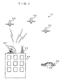
- Fig. 55A if the distance between neighboring charge areas is short, then not only is it automatically recognized that three entries have been made into charge area 1, but it is automatically recognized that two entries have been made into charge area 2.
- Fig. 55B by making the distance between neighboring charge areas wider, it is possible to avoid erroneously detecting that an entry has been made into a neighboring charge area when no such entry has actually been made. However, it is not possible to avoid erroneously detecting that charge area 1 has been entered three times.
- the second object of the present invention is to provide a charging device capable of regulating charging frequency for the passage of a vehicle near the outer edge of a charge area.
- the third object of the present invention is to stabilize this charging frequency.
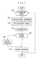
- the first aspect of the first invention is a charging device comprising: detecting means for detecting position information of a moving body; deciding means for determining a charge applicable area in predetermined map information and for determining a buffer area at a boundary between the charge applicable area and an area other than the charge applicable area, and matching the map information with the position information, and deciding an entry state indicating whether or not the moving body has at least entered into one of the charge applicable area or the buffer area; and generating means for generating charging information for the moving body based on a result of a decision by the deciding means.
- the second aspect is the charging device according to the first aspect, wherein the generating means is provided with storage means in which toll data that is determined in advance and corresponds to the entry state is stored in advance, and the charge information is generated using toll data of the storage means.
- the third aspect is the charging device according to the first or second aspect, wherein the charge applicable area is formed from at least a toll area and a non-toll area, and the buffer area is set between the toll area and the non-toll area.
- the fourth aspect is the charging device according to any of the first to third aspects, wherein the charge applicable area is formed from at least a plurality of toll areas, and the buffer area is set between adjacent toll areas.
- the fifth aspect is the charging device according to the fourth aspect, wherein the plurality of toll areas contain toll areas that have different toll systems.
- the sixth aspect is the charging device according to the fifth aspect, wherein the buffer area is provided for each plurality of toll areas.
- the seventh aspect is the charging device according to any of the first to sixth aspects, wherein a toll for the buffer area is set based on a toll of one of adjacent areas.
- the eighth aspect is the charging device according to any of the fourth to seventh aspects, wherein a toll for the buffer area is set based on a toll of an area selected from a plurality of areas surrounding the buffer area.
- the ninth aspect is the charging device according to any of the first to eighth aspects, wherein, when a history of the entry state is one in which the moving body moves from the charge applicable area to the buffer area and then back to the same charge applicable area again, generating of charge information relating to an entry into the charge applicable area is prohibited in the generating means.
- the tenth aspect is the charging device according to any of the first to ninth aspects, wherein the generating means generates charge information relating to tolls determined based on a distance traveled in the charge applicable area.
- the eleventh aspect is the charging device according to any of the first to ninth aspects, wherein the generating means is provided with storage means for storing a distance traveled in the charge applicable area when the distance traveled bridges a boundary between adjacent areas, and charge information is generated based on the stored distance traveled.
- the first aspect of the second invention is a charging device, comprising: host moving body position detecting means for detecting a position of a host moving body; storage means for storing data for charging relating to predetermined map information, charge applicable areas set in the map information, buffer areas set at boundaries between the charge applicable areas and areas other than the charge applicable areas, and the charge applicable areas; determining means for matching the map information with the position, and for determining whether or not the moving body has at least entered one of the charge applicable area and the buffer area; and charge processing means for performing charge processing for a host moving body relating to the charge applicable area based on a result of a determination by the determining means.
- the first aspect of the second invention is the charging device according to the first aspect, wherein the charge processing means performs charge processing using an IC card on which balance information is stored.
- detecting means detects position information concerning a moving body such as a vehicle or the like.
- a navigation system for mounting in a vehicle serving as the moving body which enables the display of a map for aiding traveling and providing instructions on a route to a destination can be used as this detecting means.
- this navigation system can use a GPS system to easily detect the position of the moving body in which it is mounted (i.e. the host moving body), for example, a position determined by latitude and longitude.
- a sending means such as a sender unit or the like for sending a signal that contains identifying data for identifying the moving body, and receiving on the ground the sent signal so that the position information is detected on the ground.
- the detection of the position of the moving body includes a measure of error in the detection.
- the true position of the moving body is a position within a specific range relative to the detected position, the extent of which range is determined in advance in accordance with the detection error. Accordingly, the possibility that the moving body is within a specific distance, determined in accordance with the detection error, from the detected position is included in the position information.
- a charge applicable area is determined in predetermined map information and a buffer area is set at a boundary between the charge applicable area and an area other than the charge applicable area.
- the size of this buffer area is preferably set at a size that corresponds to the detection error. It is possible to further provide map information storage means and store the map information, the charge applicable areas, and the buffer areas in this map information storage means.
- the deciding means firstly, matches the position information detected by the detecting means with the predetermined map information. Namely, because it is possible to specify the position of the moving body from the position information, this position, for example, a position set as a latitude and longitude, is able to be matched with a vehicle on predetermined map information such as a map of a predetermined area from among maps of Japan or maps of the Tokyo area. Based on the result of this matching, the deciding means decides whether or not the moving body has at least entered either one of the charge applicable area and the buffer area. The charge applicable areas and the buffer areas are set on the map information.
- the deciding means sets as the entry state this indication of whether or not the moving body has at least entered into the charge applicable area.
- the generating means generates charge information for a moving body based on the result of the deciding by the deciding means. For example, the toll that should be collected from a moving body within the charge applicable area is determined in advance. Accordingly, because a predetermined toll should be charged when a moving body enters into the charge applicable area, the toll that should be charged on the moving body that has entered into the charge applicable area is generated as charge information.
- the charge processing device of the present invention because buffer areas are provided at the boundaries of charge applicable areas, and the position of a moving body detected by detection means is matched with map information, and an entry state indicating whether or not the moving body has entered a charge applicable area is set, and charging information for the moving body is created based on this entry state, then even if there are detection errors in the detection of the position of the moving body, it is possible to accurately decide that the moving body is present within a charge applicable area, and it is possible to perform charge processing for the user of a moving body using a simple structure simply by generating charge information for a moving body in accordance with the entry state thereof, without having to install on-road devices in all the entry and exit locations such as entry and exit gates.
- the driver is unaware that the area in which the moving body is currently traveling is a charge applicable area or that the moving body is approaching and about to enter a charge applicable area. Therefore, in the charge processing device, by further providing a notification means for giving advance information, when the moving body is approaching a charge applicable area, namely, has entered a buffer area, expressing that the moving body is approaching a charge applicable area or has entered a charge applicable area based on the above position information, it is possible to notify the driver when the moving body has entered a charge applicable area or is approaching and is about to enter a charge applicable area, thereby making it easy for the driver to decide on a course of action relating to their entry into a charge applicable area or the like.
- the generating means is provided with a storage means for storing in advance toll data set in advance to correspond with the entry state. Consequently, charging information can be easily created using the toll data in the storage means.
- This toll data may be set in a plurality of levels for the type of vehicle, the travel time, and the like and these may be stored as charge tables.
- Non-toll areas such as public areas and the like may be contained inside the charge applicable area.
- the charge applicable area may comprise both areas where tolls are levied and areas where no toll is levied. Therefore, in the third aspect, a charge applicable area is formed from at least toll areas and non-toll areas and buffer areas are set between toll areas and non-toll areas.
- the toll may differ depending on which of the toll areas the position of the moving body was located in. Therefore, as in the fourth aspect, when the charge applicable area is formed from at least a plurality of toll areas, buffer areas are set between adjacent toll areas.
- a charge applicable area comprising a plurality of toll areas
- toll collection using the correct toll system can be reliably performed.
- the buffer areas are set at the boundaries between charge applicable areas and areas other than charge applicable areas.
- the toll is set for the charge applicable area, and it is also possible to set a toll for the buffer area provided at the boundary thereof.
- the moving body comes and goes between a charge applicable area and a buffer area.
- the moving body may be traveling in the vicinity of the boundary between a charge applicable area and a boundary area. Therefore, as in the ninth aspect, when a history of the entry state is one in which the moving body is shown as moving from the charge applicable area to the buffer area and then back to the same charge applicable area again, generating of charge information relating to an entry into the charge applicable area is prohibited in the generating means. If this method is employed, there is no generating of charge information for an entry into the same charge area and unnecessary toll collection can be avoided.
- the generating means to generate charge information relating to tolls determined based on a distance traveled in the charge applicable area as a category for toll collection other than a vehicle entry. Namely, a charge can be made in accordance with the distance traveled within a charge applicable area.
- the generating means is provided with storage means for storing a distance traveled in the charge applicable area when the distance traveled bridges a boundary between adjacent areas, and charge information is generated based on the stored distance traveled.
- the position of a host moving body is detected by host moving body position detecting means.
- the position of the host moving body can be specified by the moving body.
- An example of this host moving body position detecting means is the aforementioned navigation system.
- the storage means are stored predetermined map information, charge applicable areas set in the map information, buffer areas set at boundaries between the charge applicable areas and areas other than the charge applicable areas, and charge data relating to the charge applicable areas.
- the determining means matches the stored map information with the detected position, and determines whether or not the moving body has at least entered one of the charge applicable area and the buffer area.
- the charge processing means performs charge processing for a host moving body relating to the charge applicable area based on a result of a determination by the determining means.
- the charge processing means is able to perform charge processing using an IC card on which balance information is stored.
- buffer areas are provided at the boundaries of charge applicable areas, and charging information for the vehicle is created based on the position of a moving body detected by detection means and map information, then even if there are detection errors in the detection of the position of the vehicle, it is possible to accurately decide that the vehicle is present within a charge applicable area, and it is possible to generate charge information for a moving body in accordance with the entry state thereof and perform charge processing for the user of a moving body using a simple structure, without having to install on-road devices in all the entry and exit locations such as entry and exit gates.
- the first aspect of the third invention is a charging device, comprising: detecting means for detecting position information concerning the moving body; adding means for determining a buffer area in which a moving body may be expected to move to from a detected position based on position information concerning the detected moving body, and adding the buffer area to the position information; deciding means for deciding charge applicable areas in predetermined map information, for matching the position information to the map information, and for deciding an entry state indicating whether or not the moving body has at least entered the charge applicable area based on the charge applicable areas and the buffer areas; and generating means for generating charge information for the moving body based on a result of a decision by the deciding means.
- the second aspect is the charging device according to the first aspect, wherein the generating means is provided with storage means in which toll data that is determined in advance and corresponds to the entry state is stored in advance, and the charge information is generated using toll data of the storage means.
- the third aspect is the charging device according to the first or second aspects, wherein the detecting means detects position information concerning a moving body based on satellite data from a position finding satellite.
- the fourth aspect is the charging device according to any one of the first to third aspects, wherein the adding means sets the size of a buffer area based on a detection error by the detecting means.
- the fifth aspect is the charging device according to any of the first to fourth aspects, wherein the detecting means includes estimating means for estimating position information concerning a moving body based on at least one of a direction in which the moving body is traveling and a distance traveled by the moving body.
- the seventh aspect is the charging device according to the fifth aspect, wherein the adding means sets the size of a buffer area based on at least one of a direction in which the moving body is traveling and a distance traveled by the moving body used in the estimating means.
- the seventh aspect is the charging device according to any one of the first to sixth aspects, wherein the generating means generates charge information relating to tolls determined based on a distance traveled in the charge applicable area.
- detecting means detects position information concerning a moving body such as a vehicle or the like.
- a navigation system for mounting in a vehicle which enables the display of a map for aiding traveling and providing instructions on a route to a destination can be used as this detecting means.
- this navigation system can use a GPS system to easily detect the position of the host moving body, for example, a position determined by latitude and longitude.
- the detecting means it is also possible for the detecting means to detect position information concerning a moving body based on satellite data from a position finding satellite.
- a sending means such as a sender unit or the like for sending a signal that contains identifying data for identifying the host moving body, and receiving on the ground the sent signal so that the position information is detected on the ground.
- the detection of the position of the moving body includes a measure of error in the detection.
- the true position of the moving body is a position within a specific range relative to the detected position, the extent of which range is determined in advance in accordance with the detection error. Accordingly, there is a high likelihood that the position of the moving body as determined by the position information is within a specific distance, determined in accordance with the detection error. Therefore, the adding means determines a buffer area in which a moving body may be expected to move to from a detected position based on position information concerning the detected moving body. Namely, the buffer area is an area set as a range of positions specified by the position information and in which there is a high likelihood that the moving body will be located. This is added to the position information. As in the fourth embodiment, the size of this buffer area is preferably set on the basis of the detection error, for example, at a size that corresponds to the detection error.
- the deciding means firstly, matches the position information detected by the detecting means with the predetermined map information. Namely, because it is possible to specify the position of the moving body from the position information at the point when it is detected, this position, for example, a position set as a latitude and longitude, is able to be matched with a moving body on predetermined map information such as a map of a predetermined area from among maps of Japan or maps of the Tokyo area. Because the buffer areas are added to this position information, the buffer areas can be matched with the map information. The deciding means then decides an entry state indicating whether or not the moving body has at least entered the charge applicable area. The charge applicable areas are set on the map information.
- the buffer area that contains the position of the moving body that has been matched with the map information is inside a charge applicable area, it can be determined whether or not the moving body has at least entered a charge applicable area. For example, when the buffer area is completely contained inside the charge applicable area, it can be stated that the moving body is inside the charge applicable area even when the detection error is taken into account. Moreover, if a portion of the buffer area is contained inside the charge applicable area, the possibility is there that the moving body is not located inside the charge applicable area. Because of this, the deciding means decides an entry state indicating whether or not the moving body has at least entered the charge applicable area.
- the generating means generates charge information for a moving body based on the result of the deciding by the deciding means. For example, the toll that should be collected from a moving body within the charge applicable area is determined in advance. Accordingly, because a predetermined toll should be charged when a moving body enters into the charge applicable area, the toll that should be charged on the moving body that has entered into the charge applicable area is generated as charge information.
- the charge processing device of the present invention because buffer areas are added to the position information of a moving body, and the position of a moving body and the buffer zones are matched with map information, and an entry state indicating whether or not the moving body has entered a charge applicable area is set, and charging information for the moving body is created based on this entry state, then even if there are detection errors in the detection of the position of the moving body, it is possible to accurately decide that the moving body is present within a charge applicable area, and it is possible to perform charge processing for the user of a moving body using a simple structure simply by generating charge information for a moving body in accordance with the entry state thereof, without having to install on-road devices in all the entry and exit locations such as entry and exit gates.
- the driver is unaware that the area in which the moving body is currently traveling is a charge applicable area or that the moving body is approaching and about to enter a charge applicable area. Therefore, in the charge processing device, by further providing a notification means for giving advance information, when the moving body is approaching a charge applicable area, namely, when the buffer zone is approaching a charge applicable area or a portion thereof is contained within the charge applicable area, expressing that the moving body is approaching a charge applicable area or has entered a charge applicable area based on the above position information, it is possible to notify the driver when the moving body has entered a charge applicable area or is approaching and is about to enter a charge applicable area, thereby making it easy for the driver to decide on a course of action relating to their entry into a charge applicable area or the like.
- the generating means is provided with a storage means for storing in advance toll data set in advance to correspond with the entry state. Consequently, charging information can be easily created using the toll data in the storage means.
- This toll data may be set in a plurality of levels for the type of vehicle, the travel time, and the like and these may be stored as charge tables.
- the detecting means is unable to detect position information. Therefore, as in the fifth aspect, by including in the detecting means estimating means for estimating position information concerning a moving body based on at least one of a direction in which the moving body is traveling and a distance traveled by the moving body, it is possible for the detecting means to specify its own position from the distance traveled or direction of travel of the moving body or from a combination of these.
- the buffer area is set at the same size as when the position information was able to be detected by the detecting means, in some cases, the setting of the entry state into the charge applicable area may be irregular. Namely, the estimation of its position by the detecting means using the direction of travel or the distance traveled by the moving body or using a combination of these may contain errors as compared to the actual position and it may be erroneously determined that the moving body has entered the charge applicable area using the position found by estimation.
- the adding means sets the size of a buffer area based on at least one of a direction in which the moving body is traveling and a distance traveled by the moving body used in the estimating means, for example, at a size larger than the size previously set, it is possible to improve the reliability with which the entry state into the charge applicable area is decided.
- the moving body comes and goes between a charge applicable area and a buffer area.
- the moving body may be traveling in the vicinity of the boundary between a charge applicable area and a boundary area. Therefore, when the entry state is stored in a time series as history and this shows the moving body as moving from the charge applicable area to the buffer area and then back to the same charge applicable area again, generating of charge information relating to an entry into the charge applicable area is prohibited in the generating means. If this method is employed, there is no generating of charge information for an entry into the same charge area and unnecessary toll collection can be avoided.
- the generating means generates charge information relating to tolls determined based on a distance traveled in the charge applicable area. Namely, charging can be performed in accordance with the distance traveled inside a charge applicable area.
- the generating means is further provided with storage means for storing a distance traveled in the charge applicable area when the distance traveled bridges a boundary between adjacent areas, and charge information is generated based on the stored distance traveled.
- the charge processing means may perform charge processing using an IC card on which balance information is stored.
- buffer areas are determined and allocated from a detection of its own position by the detecting means, and charging information for the vehicle is created based on the position of a moving body as well as buffer areas and map information, then even if there are detection errors in the detection of the position of the vehicle, it is possible to accurately decide that the vehicle is present within a charge applicable area, and it is possible to generate charge information for a moving body in accordance with the entry state thereof and correctly perform charge processing for the user of a moving body using a simple structure, without having to install on-road devices in all the entry and exit locations such as entry and exit gates.
- the fourth invention whose aim is to provide a charging device for use in a vehicle capable of easily updating charge information is provided.
- the first aspect of the fourth invention is a charging device, comprising: detecting means for detecting a current position of a moving body; receiving means for receiving charge information including at least one of charge area data and charge data that corresponds to the charge area; storage means for storing the charge information; updating means for updating charge information stored in the storage means based on the charge information received by the receiving means; and charge processing means for performing charge processing for the moving body based on the current position of the moving body detected by the detecting means and on the charge information stored in the storage means.
- the second aspect of the fourth invention is the charge device according to the first aspect, wherein the charge information is delivered from a center by FM multiplex communication.
- the third aspect of the fourth invention is the charge device according to the first or second aspect, wherein the charge device includes deciding means for comparing the charge information stored in the storage means with the charge information received by the receiving means and deciding whether or not to update the charge information stored in the storage means.
- the detecting means detects the current position of the moving body.
- a navigation system for mounting in a vehicle which enables the display of a map for aiding traveling and providing instructions on a route to a destination can be used as this detecting means.
- this navigation system can use a GPS system to easily detect the position of the host moving body, for example, a position determined by latitude and longitude.
- the receiving means receives from the outside charge information including at least one of charge area data and charge data that corresponds to the charge area; storage means for storing the charge information.
- the charge information may be delivered from a center by FM multiplex communication.
- the charge data is data of the charge amount corresponding to the charge area. This data changes in accordance with the traffic conditions and also changes in accordance with the date, the time of day, or a combination of these.
- the updating means updates charge information stored in the storage means on the basis of the charge information received by the receiving means. It is possible, for example, for the updating of the charge information stored in the storage means to always be updated to the information received by the receiving means. Alternatively, as in the third aspect, it is also possible for the charge device to include deciding means for comparing the charge information stored in the storage means with the charge information received by the receiving means and deciding whether or not to update the charge information stored in the storage means. The updating is thus performed in accordance with the decision of the deciding means.
- the comparison of the charge information stored in the storage means and the charge information received by the receiving means may, for example, be performed by including in the charge information for comparing the age of information such as the version or date and time of transmission or the like, and by comparing the information for comparing the age that is included in the charge information received by the receiving means with the information for comparing the age that is included in the charge information stored in the storage means. It is also possible for the charge information itself to be compared and a determination made as to whether or not there is a difference therein and the information updated if there is a difference. Furthermore, it is also possible to include in the charge information the effective date and time which shows from when the charge information becomes valid (i.e. effective) and comparing the current date and time with the effective date and time included in the charge information received by the receiving means and updating the charge information if the effective date and time has already arrived.
- the charge processing means performs charge processing for the moving body on the basis of the current position of the moving body detected by the detecting means and the charge information stored in the storage means.
- the charge information stored in the storage means is updated by the updating means on the basis of charge information received by the receiving means and then charge processing is performed by the charge processing means, the effect is achieved that there is no need to read and update charge information from a storage medium or the like and it is possible to easily update all the charge information at one go.
- the fifth invention whose aim is to enable a driver to easily determine whether to enter or to avoid a charge applicable area when selecting a route is provided.
- the first aspect of the fifth invention is a charge area display device for use in a moving body, comprising: detecting means for detecting a current position of a moving body; storage means for storing information relating to a charge area; determining means for determining whether or not a charge area is included in a predetermined area that contains the current position of the moving body detected by the detecting means; notification means for making a notification that a charge area is located within the predetermined area when it is determined by the determining means that the charge area is contained within the predetermined area that includes the current position of the moving body; and charge processing means for performing charge processing for the moving body based on the current position of the moving body and information relating to the charge area stored in the storage means
- the detecting means detects the current position of the moving body.
- a navigation system for mounting in a vehicle which enables the display of a map for aiding traveling and providing instructions on a route to a destination can be used as this detecting means.
- this navigation system can use a GPS system to easily detect the position of the host moving body, for example, a position determined by latitude and longitude.
- Information relating to the charge area is stored in the storage means. It is possible to include data specifying the charge area and data on the charge amounts determined in accordance with the charge area in this information relating to the charge area.
- the determining means determines whether or not a charge area is included in a predetermined area that contains the current position of the moving body detected by the detecting means. This determination can be performed, for example, by measuring the distances to a charge applicable area in both the direction in which the vehicle is advancing and in a transverse direction substantially orthogonal to the direction in which the vehicle is advancing, and then determining whether or not these measured distances are within a predetermined distance. Note that the directions that are measured are not limited to the direction in which the vehicle is advancing and the transverse direction thereto. Alternatively, a determination may be made as to whether or not charge areas are contained within a range of 45 degrees on both sides centered on each direction.
- the notification means gives a notification that a charge area is located within the predetermined area.
- a notification may be displayed on a display screen or may be announced aurally.
- a notification is made that a charge area is located within a predetermined area when it is determined by the determining means that a charge area is contained within a predetermined area that includes the current position of a moving body, therefore, because it is possible to easily confirm that a moving body is approaching a charge area before the moving body enters the charge area, whether to enter or avoid the charge area can be easily decided.
- the second aspect of the fifth invention is the charge area display device for use in a moving body according to the first aspect, wherein the notification means makes a notification of the direction that the charge area is located using the current position as a reference.
- the notification means makes a notification of the direction that the charge area is located using the current position of the moving body as a reference, the direction in which the charge area is located can be easily confirmed and the determining of the direction of travel is simplified.
- the third aspect of the fifth invention is the charge area display device for use in a moving body according to the first or second aspect, wherein the notification means gives a notification by displaying the charge area in superposition on a map image of the vicinity of the current position of the moving body.
- the notification displays the charge area in superposition on a map image of the vicinity of the current position of the moving body.
- the color and brightness of the road of the charge area may be changed in the display, or a meshing pattern may be displayed over the entire charge area.
- the color, brightness, and halftone pattern may be altered in accordance with the remaining distance or with the amount of the charge.
- the fourth aspect is the charge area display device for use in a moving body according to the first to third aspects, wherein the notification means gives a further notification of the charge amount that corresponds to the charge area.
- the notification means gives a further notification of the charge amount that corresponds to the charge area, selecting a cheaper route is simplified.
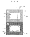
- CCD storage means
- reading and writing means (5) for reading credit information from the storage means (CRD) and for writing credit information (CRD) in the storage means
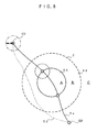
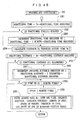
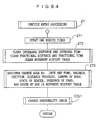
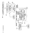
- area inside or outside detecting means (20 to 26; 2) for detecting whether its own position is inside or outside a charge area (i.e. the area j)
- information handling means (2) for generating the state information (i.e. RAEj
- RAEj 0
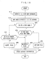
- this set time (TRj) is set at 24 hours, for example, then even if the vehicle makes repeated entries and exits into the charge area within that 24 hours, only one transit charge toll is levied. If the set time (TRj) is set at a time longer than the length of time between a departure change and an entry change when the vehicle is traveling within the charge area and close to the outer boundary of the charge area, then one transit is only recognized as one transit regardless of whether the vehicle is traveling near the outer boundary of the charge area or in the center of the charge area.
- the set time (TRj) is set at a time longer than the length of time between a departure change and an entry change when the vehicle is traveling within the charge area and close to the outer boundary of the charge area, then there is a high likelihood that travel close to the outer boundary of the charge area will be recognized as a plurality of transits through the charge area and the number of acknowledged charge transits increases. If the set time (TRj) is set to 0, for example, then for each entry and each exit detection in accordance with the inside and outside detection by the area inside or outside detecting means (20 to 26; 2), one transit charge toll payment is required and the number of acknowledged charge transits is at the maximum.
- the set time (TRj) i.e. to regulate the number of acknowledged transits. If it is desired that the volume of traffic be concentrated in the center of a charge area, the set time (TRj) can be shortened, while, if it is desired that the volume of traffic be uniform over the entire charge area, then the set time (TRj) can be lengthened.
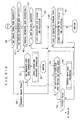
- STR set value
- this set value (STR) is set at 24 hours, for example, then even if the vehicle makes repeated entries and exits into the charge area within that 24 hours, only one transit charge toll is levied. If the set value (STR) is set at a time slightly longer than the length of time required to make one return trip through the charge area or to make one circuit around the charge area, then one transit is only recognized as one transit regardless of whether the vehicle is traveling near the outer boundary of the charge area or in the center of the charge area.
- the set value (STR) is set at a time longer than the length of time required to make one return trip through the charge area or to make one circuit around the charge area, then there is a high likelihood that travel close to the outer boundary of the charge area will be recognized as a plurality of transits through the charge area and the number of acknowledged charge transits increases. If the set value (STR) is set to 0, for example, then for each entry and each exit detection in accordance with the inside and outside detection by the area inside or outside detecting means (20 to 26; 2), one transit charge toll payment is required and the number of acknowledged charge transits is at the maximum.
- the set value (STR) i.e. to regulate the number of acknowledged transits. If it is desired that the volume of traffic be concentrated in the center of a charge area, the set value (STR) can be shortened, while, if it is desired that the volume of traffic be uniform over the entire charge area, then the set value (STR) can be lengthened.
- storage means for storing credit information (i.e. the balance); reading and writing means (5) for reading credit information (balance) from the storage means (CRD) and for writing credit information in the storage means (CRD); area inside or outside detecting means (20 to 26; 2) for detecting whether its own position is inside or outside a charge area; information handling means (2) for generating and holding the state
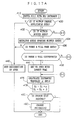
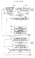
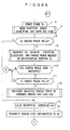
- the eighth invention is a charging device further comprising: notification means (2, 4B5, 10, SP) for urging that the storage means (CRD) be replaced when the updated value is a negative value; credit information processing means (2, 5) for updating, when there is a replacement, the credit information in the storage means after the replacement by the same amount as the negative value; and means (2, 4f2) for notifying the outside of the vehicle, when the storage means (CRD) has not been replaced, of an abnormality when set conditions are met.
- the eighth invention is a charging device, wherein a set condition is the repeating of the notification urging replacement a set two times or more.
- the eighth invention is a charging device, wherein a set condition is the passing of the set time (Tw).
- the eighth invention is a charging device, wherein a set condition is the traveling of the set distance (Lk).
- the notification means (2, 4B5, 10, SP) gives a notification urging that the storage means CRD be replaced. If the user (i.e. the driver) does not replace the storage means (CRD) at this time, then when the notification urging the replacement has been repeated a set number of times (2), abnormality notification means (2, 4f2) notifies the outside of the vehicle that there is an abnormality. Alternatively, if the set time (Tw) passes without the storage means (CRD) being replaced, the abnormality notification means (2, 4f2) notifies the outside of the vehicle that there is an abnormality. Alternatively, if the set distance (Lk) is reached without the storage means (CRD) being replaced, the abnormality notification means (2, 4f2) notifies the outside of the vehicle that there is an abnormality.
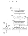
- This abnormality notification means that there has been a charging illegality or a charging violation and a person with controlling authority can on the basis of this notification, for example, stop the vehicle and require that the charge processing be completed.
- this abnormality notification is generated when, after the credit information (i.e. the balance thereof) has turned into a negative value, if there is no replacement after a replacement demand (involving repeating the notification that a replacement is required three times at predetermined time intervals - this is the first replacement demand), and thereafter, if there is still no replacement after a further replacement demand (the second replacement demand) that is made if the balance of the storage means when accessed in order to perform charge processing or to prepare for charge processing is still negative.
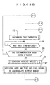
- the eighth invention is a charging device, wherein the credit information processing means (2) registers the minus value in memory (abnormality history memory) when the storage means (CRD) has not been replaced in spite of the updated value turning into a negative value.
- the eighth invention is a charging device, wherein, when the storage means (CRD) is replaced, the credit information processing means (2) updates the credit information to information in which the negative value in the memory has been paid. As a result, the demand for payment (i.e. the negative value) relating to the storage means (CRD) is paid by the storage means (CRD) that has just been inserted enabling payment of the previous amount due to be achieved with certainty.
- the eighth invention is a charging device, wherein, if the storage means (CRD) is not replaced in spite of the updated value being a negative value, the credit information processing means (2) registers the abnormality information in the abnormality history memory together with information concerning the point in time when the abnormality was generated. As a result, because information concerning the point in time (date and time) when the abnormality was generated is registered together with the charge avoidance in the abnormality history memory (2), it is possible to later pursue and confirm the charge avoidance.
- the eighth invention is a charging device, wherein the abnormality notification means (2, 4f2) includes a display means (4f2) for displaying an charging abnormality in the vehicle towards the outside of the vehicle.
- the eighth invention is a charging device, further comprising: abnormality information reading means (2) for outputting data of the abnormality history memory in accordance with a specific input; and abnormality data erasing means (2) for erasing data representing an abnormality in the abnormality history memory in response to an erasure instruction with the condition that the abnormality information reading means (2) has output data.
- a charging controller i.e. an employee of the charging system operating body or a member of the police forces with responsibility for the system
- who has stopped a vehicle whose display means (2, W4f2, W4f3) is displaying an abnormality gives a specific input to the abnormality information reading means and is thus able to output data of the abnormality history memory.
- this output data is displayed on the display in a vehicle and is also printed out on the printer of a data collector held by the charge controller. It is also registered on the storage means inside the data collector.
- the charge controller displays this printout and obtains an agreement on the contents of the printed data and is thus able to seek payment for the unpaid amount.
- the charge controller gives an erasure instruction (i.e. an instruction to clear) to the abnormality data erasing means (2). Because the data is output first, the abnormality data erasing means (2) erases data representing an abnormality in the abnormality history memory (2) in accordance with the erasure instruction. As a result, the illegality information for which payment has been received is erased from the memory.
- the data erasure of the abnormality history memory (2) is performed on the preconditions that the erasure instruction (instruction to clear) is input and data is output in response to a specific input, if only the charge controller is able to make the specific input, then the reliability of the protection of the abnormality (illegality) information in the abnormality history memory (2) is high.
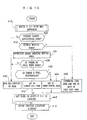
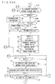
- the information handling means begins to measure how much time has passed, and if the detection of whether the position is inside or outside the charge area j changes from outside the charge area j to inside the charge area j, then the information handling means makes the measurement of how much time has passed invalid and holds the j state information (i.e.
- the information handling means (2) keeps retaining the state information showing that the vehicle is located in charge area 1. Therefore, even if the determination by the area inside or outside detecting means as to whether the vehicle is inside or outside an area swings between inside area 1 and inside area 2 within the set time (TRj), there is no changing of the state information. Moreover, if the vehicle travels the route shown in Fig. 55B, and even if the vehicle travels the route shown in Fig. 55A, there is no change in the state information (i.e.
- the fourth aspect of the ninth invention is a charging device further comprising: notification means (2, 4B5, 10, SP) for urging that the storage means (CRD) be replaced when the updated value is a negative value; credit information processing means (2, 5) for updating, when there is a replacement, the credit information in the storage means after the replacement by the same amount as the negative value; and means (2, 4f2) for notifying the outside of the vehicle, when the storage means (CRD) has not been replaced, of an abnormality when set conditions are met.
- the fifth aspect of the ninth invention is a charging device, wherein a set condition is the repeating of the notification urging replacement a set two times or more.
- the sixth aspect of the ninth invention is a charging device, wherein a set condition is the passing of the set time (Tw).
- the seventh aspect of the ninth invention is a charging device, wherein a set condition is the traveling of the set distance (Lk).
- the notification means (2, 4B5, 10, SP) gives a notification urging that the storage means CRD be replaced. If the user (i.e. the driver) does not replace the storage means (CRD) at this time, then when the notification urging the replacement has been repeated a set number of times (2), abnormality notification means (2, 4f2) notifies the outside of the vehicle that there is an abnormality. Alternatively, if the set time (Tw) passes without the storage means (CRD) being replaced, the abnormality notification means (2, 4f2) notifies the outside of the vehicle that there is an abnormality. Alternatively, if the set distance (Lk) is reached without the storage means (CRD) being replaced, the abnormality notification means (2, 4f2) notifies the outside of the vehicle that there is an abnormality.
- This abnormality notification means that there has been a charging illegality or a charging violation and a person with controlling authority can on the basis of this notification, for example, stop the vehicle and require that the charge processing be completed.
- this abnormality notification is generated when, after the credit information (i.e. the balance thereof) has turned into a negative value, if there is no replacement after a replacement demand (involving repeating the notification that a replacement is required three times at predetermined time intervals - this is the first replacement demand), and thereafter, if there is still no replacement after a further replacement demand (the second replacement demand) that is made if the balance of the storage means when accessed in order to perform charge processing or to prepare for charge processing is still negative. Moreover, if the balance is still negative when the set time Tw has passed after the first replacement demand, as well as if the set distance Lk has been reached after the first replacement demand, then the abnormality notification is made to the outside of the vehicle.
- the eighth aspect of the ninth invention is a charging device, wherein the credit information processing means (2) registers the minus value in memory (abnormality history memory) when the storage means (CRD) has not been replaced in spite of the updated value turning into a negative value.
- the balance of the storage means (CRD) becomes negative as a result of the charge processing and the payment thereof is not made, the demand for the payment (the negative value) is saved in memory. The demand for payment to be made is not deleted even if the storage means (CRD) is taken out.
- the ninth aspect of the ninth invention is a charging device, wherein, when the storage means (CRD) is replaced, the credit information processing means (2) updates the credit information to information in which the negative value in the memory has been paid. As a result, the demand for payment (i.e. the negative value) relating to the storage means (CRD) is paid by the storage means (CRD) that has just been inserted enabling payment of the previous amount due to be achieved with certainty.
- the tenth aspect of the ninth invention is a charging device, wherein, if the storage means (CRD) is not replaced in spite of the updated value being a negative value, the credit information processing means (2) registers the abnormality information in the abnormality history memory together with information concerning the point in time when the abnormality was generated.
- the eleventh aspect of the ninth invention is a charging device, wherein the abnormality notification means (2, 4f2) includes a display means (4f2) for displaying an charging abnormality in the vehicle towards the outside of the vehicle. A person with controlling authority can visually confirm vehicles with this abnormality display and stop the vehicle on the road and require that the charge processing be completed.
- the twelfth aspect of the ninth invention is a charging device, further comprising: abnormality information reading means (2) for outputting data of the abnormality history memory in accordance with a specific input; and abnormality data erasing means (2) for erasing data representing an abnormality in the abnormality history memory in response to an erasure instruction with the condition that the abnormality information reading means (2) has output data.
- a charging controller i.e. an employee of the charging system operating body or a member of the police forces with responsibility for the system
- W4f2, W4f3 is displaying an abnormality gives a specific input to the abnormality information reading means and is thus able to output data of the abnormality history memory.
- this output data is displayed on the display in a vehicle and is also printed out on the printer of a data collector held by the charge controller. It is also registered on the storage means inside the data collector.
- the charge controller displays this printout and obtains an agreement on the contents of the printed data and is thus able to seek payment for the unpaid amount.
- the charge controller gives an erasure instruction (i.e. an instruction to clear) to the abnormality data erasing means (2). Because the data is output first, the abnormality data erasing means (2) erases data representing an abnormality in the abnormality history memory (2) in accordance with the erasure instruction. As a result, the illegality information for which payment has been received is erased from the memory.
- the data erasure of the abnormality history memory (2) is performed on the preconditions that the erasure instruction (instruction to clear) is input and data is output in response to a specific input, if only the charge controller is able to make the specific input, then the reliability of the protection of the abnormality (illegality) information in the abnormality history memory (2) is high.
- charge processing it is possible to perform charge processing to achieve various objectives.
- This can be achieved by establishing various charge categories, for example, entry into an area, distance traveled within an area, travel time within an area, and time spent in congested traffic). For example, if an area in which the level of traffic congestion needs to be reduced is set as a charge area, and by measuring the length of time spent in this area when traffic is congested (for example, is traveling at less than 20 Km/h) and charging a toll based on time units for this length of time, then by increasing the cost of driving through such a congested area, drivers can be made to want themselves to avoid congested areas.
- charge processing is to be performed based on how much time a vehicle spends in an area in congested traffic
- measuring of the length of time that passes with the vehicle speed below a set value for example, 20 km/h
- payment processing of a charge amount proportional to the measured value is performed when the vehicle leaves the charge area.
- a charge device is provided with a processing algorithm which only performs a specific item from among various charging categories (for example, area entry, distance traveled in that area, travel time in that area, and time spent in congested traffic), then this device is unable to respond to future alterations to the charge system or charge area settings for other charge areas.
- various charging categories for example, area entry, distance traveled in that area, travel time in that area, and time spent in congested traffic
- the first aspect of the tenth invention is a charging device comprising: storage means (CRD) for storing credit information (i.e.
- reading and writing means (5) for reading credit information from the storage means (CRD) and for writing credit information in the storage means (CRD); area inside or outside detecting means (20 to 26; 2) for detecting whether its own position is inside or outside a charge area; and charge processing means (2) charge processing means (2) for calculating the toll (Y) for transit through a charge area and updating credit information (balance) in the storage means (CRD) by that amount via the reading and writing means (5) in accordance with a toll charged for a charge area (j, k), wherein there is further provided unit price memory means (2) for holding charge unit prices (A 1 , A 2 , A 3 , A 4 ) for each charge category (i.e.
- charge area No. 1 has a system where charges are based on number of entries into the area and distance traveled within the area.
- Charge area 2 has a system where charges are based on number of entries into the area and congested travel time.
- Charge area 3 has a system where charges are based only on distance traveled within the area.
- Charge area 4 has a system where charges are based on number of entries into the area and travel time within the area.
- each of the values A 1 , A 2 , A 3 , A 4 can be set so that the intended charge system is achieved.
- the unit price memory means (2) holds charge unit prices (A 1 , A 2 , A 3 , A 4 ) for each charge category of addresses of each charge area, and the charge variable measuring means (2) measures the actual values of each charge category (i.e.
- the charge system is changed, because the transit toll calculation processing is the same, there is a high degree of adaptability in the charge processing of each type of charge processing system and the data processing for the charge processing does not have to be complicated.
- the second aspect of the tenth invention is a charge device, wherein the charge unit prices (A 1 , A 2 , A 3 , A 4 ) include zero, which indicates that there is no charge (Table 2), and the charge variable measuring means (2) measures at least the values of the charge categories in order to obtain actual values of charge unit prices that are not zero (276 to 281 of Fig.
- the fifth aspect of the tenth invention is a charge device, wherein the charge unit prices include a per entry charge toll A 1 for each entry into a charge area, a distance charge toll A 2 for distance traveled inside a charge area, a time charge toll A 3 for travel time inside a charge area, and a time charge toll A 4 for congested travel time inside a charge area; and the charge variable measuring means (2) measures the number of entries into an area Z, the distance traveled within an area D, the amount of time spent in an area T, and the amount of time in congested traffic spent in an area C; and the charge processing means (2) calculates the transit toll (Y) for each charge area by applying the charge unit prices A 1 , A 2 , A 3 , A 4 of the charge areas for calculating transit tolls and the number of entries Z, the distance traveled D, the travel time T, and the congested travel time C measured by the charge variable measuring means (2) to a sum of products calculation calculated using the sum of the products of each charge unit price and each variable
- a charge processing system in a vehicle that uses a prepaid card in a vehicle to update and store on a card the remaining balance when a charge amount is deducted from the balance on the card, sometimes the card balance is changed into a negative value (i.e. into an unpaid amount), namely, the card balance is not sufficient to enable payment to be made by the charge processing.
- the user is notified of the card balance insufficiency, and that it be urged that the card be replaced.
- the balance thereof is updated to a value from which the previous insufficient amount has been deducted.
- a notification of a charging abnormality is made to the outside of the vehicle by a charging abnormality display and/or by wireless communication to a center station, thereby simplifying exposure of the negative value in order to enforce payment thereof.
- the balance of the prepaid card is insufficient, then if a new card is used even though there is a balance remaining on the old card, then the balance on the old card is wasted.
- the card is used with the balance thereof being too small, then the balance becomes a negative value while it is being used.
- warning of an illegality is given such as a charge abnormality display being made to the outside of the vehicle and/or a charge abnormality notification being given to the center station by wireless communication. Therefore, when the old card is replaced with the new card, warning of an illegality has already been given and the user is made to feel extremely uncomfortable.
- the eleventh invention is proposed which has as the first aim thereof the providing of sufficient time for the card replacement to be completed, and in addition, the aims of reliably performing charge collection, simplifying the exposing by a charge controller of vehicles that are unable to pay a charge, and simplifying the collection by a controller of unprocessed charges.
- the first aspect of the eleventh invention is a charge device, comprising: storage means (CRD) for storing (1) credit information (i.e.
- reading and writing means (5) for reading credit information from the storage means (CRD) and for writing credit information (CRD) in the storage means; charge processing means (2) for updating credit information in the storage means (CRD) via the reading and writing means (5) in accordance with a toll charged; notification means (2, 4B5, 10, SP) for urging that the storage means (CRD) be replaced when the updated value is a negative value; credit information processing means (2, 5) for updating, when there is a replacement, the credit information in the storage means after the replacement by the same amount as the negative value; abnormality notification means (2, 4f2) notifies the outside of the vehicle that there is an abnormality; and means (2, 4f2) for notifying the outside of the vehicle of an abnormality, when the storage means (CRD) has not been replaced and when at least one of: a notification urging a replacement has been repeated a set two times or more (2), a set time (Tw) has passed, and a set distance (Lk) has been reached has occurred.
- Tw set time
- Lk
- the notification means (2, 4B5, 10, SP) gives a notification urging that the storage means CRD be replaced. If the user (i.e. the driver) does not replace the storage means (CRD) at this time, then when the notification urging the replacement has been repeated a set number of times (2), abnormality notification means (2, 4f2) notifies the outside of the vehicle that there is an abnormality. Alternatively, if the set time (Tw) passes without the storage means (CRD) being replaced, the abnormality notification means (2, 4f2) notifies the outside of the vehicle that there is an abnormality. Alternatively, if the set distance (Lk) is reached without the storage means (CRD) being replaced, the abnormality notification means (2, 4f2) notifies the outside of the vehicle that there is an abnormality.
- This abnormality notification means that there has been a charging illegality or a charging violation and a person with controlling authority can on the basis of this notification, for example, stop the vehicle and require that the charge processing be completed.
- this abnormality notification is generated when, after the credit information (i.e. the balance thereof) has turned into a negative value, if there is no replacement after a replacement demand (involving repeating the notification that a replacement is required three times at predetermined time intervals - this is the first replacement demand), and thereafter, if there is still no replacement after a further replacement demand (the second replacement demand) that is made if the balance of the storage means when accessed in order to perform charge processing or to prepare for charge processing is still negative. Moreover, if the balance is still negative when the set time Tw has passed after the first replacement demand, as well as if the set distance Lk has been reached after the first replacement demand, then the abnormality notification is made to the outside of the vehicle.
- the second aspect of the eleventh invention is a charging device, wherein the credit information processing means (2) registers the minus value in memory (abnormality history memory) when the storage means (CRD) has not been replaced in spite of the updated value turning into a negative value.
- the credit information processing means (2) registers the minus value in memory (abnormality history memory) when the storage means (CRD) has not been replaced in spite of the updated value turning into a negative value.
- the third aspect of the eleventh invention is a charging device, wherein, when the storage means (CRD) is replaced, the credit information processing means (2) updates the credit information to information in which the negative value in the memory has been paid. As a result, the demand for payment (i.e. the negative value) relating to the storage means (CRD) is paid by the storage means (CRD) that has just been inserted enabling payment of the previous amount due to be achieved with certainty.
- the fourth aspect of the eleventh invention is a charging device, wherein, if the storage means (CRD) is not replaced in spite of the updated value being a negative value, the credit information processing means (2) registers the abnormality information in the abnormality history memory together with information concerning the point in time when the abnormality was generated.
- the fifth aspect of the eleventh invention is a charging device, wherein the abnormality notification means (2, 4f2) includes a display means (4f2) for displaying an charging abnormality in the vehicle towards the outside of the vehicle. A person with controlling authority can visually confirm vehicles with this abnormality display and stop the vehicle on the road and require that the charge processing be completed.
- the sixth aspect of the eleventh invention is a charging device, further comprising: abnormality information reading means (2) for outputting data of the abnormality history memory in accordance with a specific input; and abnormality data erasing means (2) for erasing data representing an abnormality in the abnormality history memory in response to an erasure instruction with the condition that the abnormality information reading means (2) has output data.
- a charging controller i.e. an employee of the charging system operating body or a member of the police forces with responsibility for the system
- who has stopped a vehicle whose display means (2, W4f2, W4f3) is displaying an abnormality gives a specific input to the abnormality information reading means and is thus able to output data of the abnormality history memory.
- this output data is displayed on the display in a vehicle and is also printed out on the printer of a data collector held by the charge controller. It is also registered on the storage means inside the data collector.
- the charge controller displays this printout and obtains an agreement on the contents of the printed data and is thus able to seek payment for the unpaid amount.
- the charge controller gives an erasure instruction (i.e. an instruction to clear) to the abnormality data erasing means (2). Because the data is output first, the abnormality data erasing means (2) erases data representing an abnormality in the abnormality history memory (2) in accordance with the erasure instruction. As a result, the illegality information for which payment has been received is erased from the memory.
- the data erasure of the abnormality history memory (2) is performed on the preconditions that the erasure instruction (instruction to clear) is input and data is output in response to a specific input, if only the charge controller is able to make the specific input, then the reliability of the protection of the abnormality (illegality) information in the abnormality history memory (2) is high.
- a charge processing system in a vehicle that uses a prepaid card in a vehicle to update and store on a card the remaining balance when a charge amount is deducted from the balance on the card, devices (i.e. hardware) for organizing information necessary for charge processing and programs (i.e. software) are necessary. It is possible that, due to breakdowns in these or else due to imperfect operation caused by a user tinkering with the hardware or software so as to avoid paying a charge, the charge processing might not be completed in the vehicle. Measures against this happening are therefore desirable.
- a GPS position finder is mounted in the vehicle and, based on the ground position of the vehicle, if charge processing to calculate the amount of the charge and update the card balance to a value from which that charge amount has been deducted is performed at the point when the vehicle enters a charge area or when a vehicle departs from a charge area or when a vehicle is in a charge area corresponding to each time the vehicle makes one transit through the area or corresponding to the distance traveled by the vehicle within the area or corresponding to the length of time spent by the vehicle in the area, then, for example, if the GPS antenna is intentionally shielded so that it is unable to receive radio signals from a GPS satellite, then the charge processing is not performed because it is not recognized that the vehicle has entered into the charge area.
- an angular velocity sensor and a movement distance calculating device are provided, and the ground position is ascertained by gyroscopic navigation in which the ground position information is updated by ascertaining the direction in which the vehicle is traveling by calculating the amount of change in the travel direction of the vehicle from the angular velocity detected by the angular velocity sensor, and at the same time, calculating the distance traveled by counting speed pulses one of which is generated each time a wheel of the vehicle rotates a predetermined minute angle or calculating the distance traveled by calculating the vehicle speed based on the speed pulses and then integrating the vehicle speed, then if either the vehicle speed pulse signal generator or a signal line thereof is broken, the vehicle ground position becomes unclear and the charge processing cannot be performed.
- the charge processing is based on the distance traveled within a charge area, then if the distance traveled by the vehicle is found from the integral value of the vehicle speed pulses or the integral value of the vehicle speed calculated on the basis of the vehicle speed pulses, if the vehicle speed pulses are cut off before they reach the counting device, then the charge processing cannot be carried out.
- the twelfth to sixteenth inventions are provided with the aims of automatically supervising the inability of a charging device mounted in a vehicle to perform charge processing, simplifying the exposing by a charge controller of vehicles that are unable to perform charge processing, and the simplifying of the collection by a controller of unpaid tolls.
- the twelfth invention is a charge device, comprising: storage means (CRD) for storing credit information (i.e.
- reading and writing means (5) for reading credit information from the storage means (CRD) and for writing credit information in the storage means (CRD); vehicle entry detecting means (20 to 26; 2) for detecting an entry of a vehicle into a charge area; charge processing means (2) for updating credit information in the storage means (CRD) via the reading and writing means (5) in accordance with a toll charged in response to a transit through the charge area; means for detecting at least one abnormality in each of the above means that causes a problem in the charge processing of the charge processing means (2); abnormality information registering means (2) for registering in abnormality history memory (2) an abnormality detected by the abnormality detecting means together with information (i.e. the date and time) on the point in time when it was generated; and display means (2, W4f2, W4f3) for displaying to the outside of a vehicle the fact that data indicating an abnormality is present in the abnormality history memory.
- an abnormality that causes a problem in the charge processing is registered in the abnormality history memory together with information (i.e. the date and time) on the point in time when it was generated, and the abnormality in the charge processing is displayed to the outside of the vehicle by the display means (2, W4f2, W4f3).
- the charge controller is able to distinguish vehicles on the road having a charging abnormality by the presence or otherwise of this display enabling the controller to easily expose vehicles unable to pay the charge.
- the charge controller can then stop vehicles with this display and require payment of the charge as well as requiring that measures to enable normal charge processing to be carried out be performed.
- the thirteenth invention is a charge device, comprising: GPS position finding means (ANTg, 20 to 22) for detecting a ground position of a vehicle; storage means (CRD) for storing credit information (i.e. the card balance); reading and writing means (5) for reading credit information from the storage means (CRD) and for writing credit information in the storage means (CRD); vehicle entry detecting means (20 to 26; 2) for detecting an entry of a vehicle into a charge area based on a ground position detected by the GPS position finding means (ANTg, 20 to 22); charge processing means (2) for updating credit information in the storage means (CRD) via the reading and writing means (5) in accordance with a toll charged in response to a transit through the charge area; means (2) for detecting at least one abnormality in each of the above means that causes a problem in the charge processing of the charge processing means (2); and abnormality information registering means (2) for registering in abnormality history memory (2) data indicating an abnormality together with information (i.e.
- the term "antenna shielding" means, for example, a state in which the reception level from all GPS satellites able to be normally received by a GPS receiver at a location open to the sky is 0 (i.e. absolutely no reception is possible). If this continuously shielded state continues for a set distance or more after the shielding first started, then it is considered that the GPS position finding has been intentionally disabled and a GPS abnormality is registered in the abnormality history memory.
- the value set for the distance traveled is determined by the travel distance over which the GPS radio waves are continuously cut off due to the maximum length and the like of natural or man made obstacles such as tunnels, mountains, blocks of buildings and the like existing in that region.
- the set value is determined as a predetermined time value TVa obtained by dividing a set travel distance value (e.g. 50 m) by the traveling speed of the vehicle which is obtained by a speed calculation using the vehicle speed pulses, and a GPS abnormality is registered in the abnormality history memory (2) when the GPS measurement is continuously impossible for TVa or longer.
- the measuring of how much time is passing also stops.
- the fourteenth invention is a charge device, comprising: storage means (CRD) for storing credit information (i.e. the card balance); reading and writing means (5) for reading credit information from the storage means (CRD) and for writing credit information in the storage means (CRD); vehicle entry detecting means (20 to 26; 2) for detecting an entry of a vehicle into a charge area; charge processing means (2) for updating in accordance with a toll charged credit information in the storage means (CRD) via the reading and writing means (5) in response to a transit through the charge area; means (2) for detecting an abnormality in the above storage means (CRD) or the reading and writing means (5) that causes a problem in the charge processing of the charge processing means (2); and means (2) for generating a warning (warning notification 1) when the abnormality detecting means (2) detects an abnormality either until the abnormality disappears or until the power that enables the vehicle to run is turned off (i.e. until IGsw is off).
- a warning warning
- the warning generating means (2) generates a warning (warning notification 1). Because this warning is continued until the storage means (CRD) can be read and written to correctly and the charge processing can be carried out (i.e. the balance is positive), or until the car is parked, the driver cannot simply persevere and put up with the noise.
- the above charge device (3) further provided with abnormality information registering means (2) for registering in the abnormality history memory an abnormality detected by the abnormality detecting means together with information on the point in time (i.e. the date and time) when it was generated.
- the fifteenth invention is a charge device, comprising: GPS position finding means (ANTg, 20 to 22) for detecting a ground position of a vehicle; storage means (CRD) for storing credit information (i.e.
- reading and writing means (5) for reading credit information from the storage means (CRD) and for writing credit information in the storage means (CRD); vehicle entry detecting means (2) for detecting an entry of a vehicle into a charge area based on a ground position detected by the GPS position finding means (ANTg, 20 to 22); charge processing means (2) for updating credit information in the storage means (CRD) via the reading and writing means (5) in accordance with a toll charged in response to a transit through the charge area; and abnormality information registering means (2) for registering in abnormality history memory (2) data indicating an abnormality together with information (i.e. the date and time) on the point in time when it was generated when the frequency of the generation of vehicle speed pulses is abnormally lower than the frequency of generation corresponding to the speed of the vehicle as calculated by the GPS position finding means (ANTg, 20 to 22).
- the vehicle speed pulses are used for calculating the distance traveled. Moreover, they are also used calculating distance and direction of travel in combination with direction detection by gyro when position finding by GPS position finding means (ANTg, 20 to 22) is not possible, such as in a tunnel or the like.
- position finding by GPS position finding means ANTg, 20 to 22
- the distance charge amount is 0 or only a very miniscule amount.
- the frequency at which the vehicle speed pulses are generated is abnormally lower than the frequency at which they would be generated if they corresponded to the vehicle speed as calculated by the GPS position finding means (ANTg, 20 to 22).
- the abnormality information registering means (2) registers the data indicating this abnormality together with information concerning the point in time (time of day) when the abnormality was generated in the abnormality history memory (2). As a result, it is thereafter possible to confirm the history of the vehicle speed pulses abnormality and pursue unpaid tolls.
- the sixteenth invention is a charge device, comprising: position finding means (20, 25) that include angular velocity detecting means (25) for detecting a ground position of a vehicle; storage means (CRD) for storing credit information (i.e. the card balance); reading and writing means (5) for reading credit information from the storage means (CRD) and for writing credit information in the storage means (CRD); vehicle entry detecting means (2) for detecting an entry of a vehicle into a charge area based on a ground position detected by the position finding means (20, 25); charge processing means (2) for updating credit information in the storage means (CRD) via the reading and writing means (5) in accordance with a toll charged in response to a transit through the charge area; and abnormality information registering means (2) for registering, in abnormality history memory (2) data indicating an abnormality together with information (i.e. the date and time) concerning the point in time when it was generated, when the frequency of the generation of vehicle speed pulses is abnormally low at a time when the angular velocity detected by the angular
- vehicle speed pulse abnormalities are determined using angular speed detection means (25). If the vehicle turns (i.e. if the vehicle turns left or right at an intersection or changes the line of driving), then the vehicle is moving and the angular velocity detecting means (25) detects a sizeable angular velocity.
- the abnormality information registering means (2) registers data indicating the vehicle speed pulse abnormality together with information (i.e. the date and time) concerning the point in time when it was generated in abnormality history memory (2). As a result, it is thereafter easy to confirm the history of the vehicle speed pulses abnormality and track the state of abnormality.
- the charge device according to any of the above (39), (41), (42), or (43), further comprises display means (2, W4f2, W4f3) for displaying to the outside of a vehicle the fact that data indicating an abnormality is present in the abnormality history memory (2).
- An abnormality in the charge processing is displayed to the outside of the vehicle by the display means (2, W4f2, W4f3).
- the charge controller is thus able to distinguish vehicles on the road having a charging abnormality by the presence or otherwise of this display enabling the controller to easily expose vehicles unable to pay the charge.
- the charge controller can then stop vehicles with this display and require payment of the charge as well as requiring that measures to enable normal charge processing to be carried out be performed.
- the charge device further comprises: abnormality information reading means (2) for outputting data of the abnormality history memory (2) in accordance with a specific input; and abnormality data deleting means (2) for deleting data indicating an abnormality in the abnormality history memory (2) in response to a delete instruction (i.e. an instruction to clear) on the precondition that the abnormality information reading means (2) has output data.
- abnormality information reading means (2) for outputting data of the abnormality history memory (2) in accordance with a specific input
- abnormality data deleting means (2) for deleting data indicating an abnormality in the abnormality history memory (2) in response to a delete instruction (i.e. an instruction to clear) on the precondition that the abnormality information reading means (2) has output data.
- a charging controller i.e. an employee of the charging system operating body or a member of the police forces with responsibility for the system
- who has stopped a vehicle whose display means (2, W4f2, W4f3) is displaying an abnormality gives a specific input to the abnormality information reading means and is thus able to output data of the abnormality history memory.
- this output data is displayed on the display in a vehicle and is also printed out on the printer of a data collector held by the charge controller. It is also registered on the storage means inside the data collector.
- the charge controller displays this printout and obtains an agreement on the contents of the printed data (i.e. that there has been a breakdown or an illegal action) and is thus able to seek payment for the unpaid amount or demand the repair of the charge processing system.
- the charge controller gives an erasure instruction (i.e. an instruction to clear) to the abnormality data erasing means (2). Because the data is output first, the abnormality data erasing means (2) erases data representing an abnormality in the abnormality history memory (2) in accordance with the erasure instruction. As a result, the illegality information for which payment has been received is erased from the memory.
- the data erasure of the abnormality history memory (2) is performed on the preconditions that the erasure instruction (instruction to clear) is input and data is output in response to a specific input, if only the charge controller is able to make the specific input, then the reliability of the protection of the abnormality (illegality) information in the abnormality history memory (2) is high.
- Fig. 1 is a block diagram showing the conceptual structure of an automatic charging system according to an embodiment of the present invention.
- Fig. 2 is a block diagram showing the schematic structure of a general center established on the ground side in the automatic charging system of the first embodiment.
- Fig. 3 is a block diagram showing the schematic structure of an in-vehicle device in the automatic charging system of the first embodiment.
- Figs. 4A through 4C are perspective views showing the schematic structure of a display device.
- Fig. 5 is a flow chart showing the flow of information transmission processing executed in the general center of the first embodiment.
- Fig. 6 is a flow chart showing the flow of processing to fix a charge applicable area executed in the in-vehicle device of the first embodiment.
- Fig. 7 is a flow chart showing the flow of charge processing executed in the in-vehicle device of the first embodiment.
- Fig. 8 is an image diagram showing a charge applicable area.
- Fig. 9 is an explanatory view for explaining an example for determining a charge applicable area.
- Fig. 10 is an explanatory view for explaining a detection error of the first embodiment.
- Figs. 11A through 11D are explanatory views for explaining the area determination around a buffer area of the first embodiment.
- Fig. 12 is a line drawing showing the basic structure of a charge applicable area of the second embodiment.
- Fig. 13 is a line drawing showing a charge applicable area of the second embodiment.
- Fig. 14 is a flow chart showing the flow of processing of the second embodiment.
- Fig. 15 is a line drawing showing the path traveled by a vehicle through the charge applicable area of the third embodiment.
- Fig. 16 is a flow chart showing the flow of processing of the third embodiment.
- Figs. 17A and 17B are flow charts showing the flow of processing of the fourth embodiment:
- Fig. 18 is a line drawing showing the path traveled by a vehicle through the charge applicable area of the fourth embodiment.
- Fig. 19 is a flow chart showing the flow of processing to fix a charge applicable area executed in the in-vehicle device of the fifth embodiment.
- Fig. 20 is an explanatory view showing detection errors of the fifth embodiment.
- Figs. 21A through 21D are explanatory views for explaining the area determination around a buffer area of the fifth embodiment.
- Fig. 22 is a flow chart showing the flow of charge processing executed in the in-vehicle device of the sixth embodiment.
- Fig. 23 is a block diagram showing the schematic structure of an in-vehicle device in the automatic charging system of the seventh embodiment.
- Fig. 24 is a flow chart showing the flow of information transmission processing executed in a general center.
- Fig. 25 is an image diagram showing a charge applicable area.
- Fig. 26 is a flow chart showing the flow of processing to determine a charge applicable area executed in an in-vehicle device.
- Figs. 27A and 27B are flow charts showing the flow of information reception processing executed in an in-vehicle device.
- Fig. 28 is a flow chart showing the flow of charge processing executed in an in-vehicle device.
- Fig. 29 is a block diagram showing the schematic structure of an in-vehicle device in the automatic charging system of the eighth embodiment.
- Fig. 30 is an image diagram showing a charge applicable area.
- Fig. 31 is a flow chart showing the flow of processing to determine a charge applicable area executed in an in-vehicle device.
- Fig. 32 is a flow chart showing the flow of the processing operation of an in-vehicle device.
- Figs. 33A and 33B show examples of the display when a vehicle is approaching a charge applicable area.
- Fig. 34 shows an example of the display when a vehicle is approaching a charge applicable area.
- Fig. 35 is a block diagram showing an outline of the structure of the system of the ninth embodiment of the present invention.
- Fig. 36 is a block diagram showing the structure of the in-vehicle charging device 1 shown in Fig. 35.
- Fig. 37 is a perspective view showing the exterior of the case housing the main portions of the in-vehicle charging device 1 shown in Fig. 36.
- Fig. 38 is a block diagram showing the structure of the notification station 30 shown in Fig. 35.
- Figs. 39A and 39B are flow charts showing a portion of the charge control operation of the charge control ECU 2 shown in Fig. 37.
- Figs. 40A and 40B are flow charts showing the remaining portions of the charge control operation of the ECU 2 shown in Fig. 37.
- Figs. 41A and 41B are flow charts showing the content of the "card check" 4 shown in Figs. 39A and 39B.
- Fig. 42 is a flow chart showing the content of the "vehicle entry processing" 27 shown in Figs. 40A and 40B.
- Fig. 43 is a flow chart showing a portion of the content of the "charge abnormality check" CCU1 shown in Fig. 42.
- Fig. 44 is a flow chart showing another portion of the content of the "charge abnormality check" CCU1 shown in Fig. 42.
- Fig. 45 is a flow chart showing the remaining portions of the content of the "charge abnormality check" CCU1 shown in Fig. 42.
- Fig. 46 is a flow chart showing the content of the "intermediate processing" 28 shown in Figs. 40A and 40B.
- Fig. 47 is a flow chart showing the content of the "vehicle exit processing" 30 shown in Figs. 40A and 40B.
- Fig. 48 is a flow chart showing a portion of the interrupt processing 1 DRI1 by the charge control ECU 2 shown in Fig. 37 in response to the reception of a radio signal.
- Fig. 49 is a flow chart showing the remaining portions of the interrupt processing 1 DRI1 by the charge control ECU 2 shown in Fig. 37 in response to the reception of a radio signal.
- Fig. 50 is a flow chart showing the content of the "abnormality history memory data processing" MDP shown in Figs. 39A and 39B.
- Figs. 51A and 51B are flow charts showing the content of interrupt processing 2 DRI2 by the controller unit 32 shown in Fig. 38 in response to the arrival of a signal from the energizing device 31 or the modem unit 34.
- Fig. 52 is a flow chart showing the content of "toll collection & movement history collection" CRC performed repeatedly by the controller unit 32 shown in Fig. 38.
- Figs. 53A and 53B are flow charts showing a portion of the charge control operation of the charge control ECU 2 of the tenth embodiment.
- Figs. 54A and 54B are flow charts showing a portion of the charge control operation of the charge control ECU 2 of the eleventh embodiment.
- Figs. 55A and 55B are plan views showing charge areas set in a road network.
- Figs. 56A and 56B are flow charts showing the remaining portions of the charge control operation of the charge control ECU 2 in the twelfth embodiment.
- Figs. 57A and 57B are flow charts showing the content of interrupt processing 2 DRI2 by the controller unit 32 in response to the arrival of a signal from the energizing device 31 or the modem unit 34.
- Figs. 58A and 58B are flow charts showing a portion of the charge control operation of the charge control ECU 2 in the thirteenth embodiment.
- Figs. 59A and 59B are flow charts showing the remaining portions of the charge control operation of the charge control ECU 2 of the fourteenth embodiment.
- Fig. 60 is a flow chart showing the content of the "vehicle entry processing" 27 shown in Figs. 59A and 59B.
- Figs. 61A and 61B are flow charts showing a portion of the interrupt processing 1 DRI1 by the charge control ECU 2 of the fourteenth embodiment in response to the reception of a radio signal.
- Fig. 62 is a plan view showing charge areas set in a road network.
- Figs. 63A and 63B are flow charts showing the remaining portions of the charge control operation of the charge control ECU 2 of the fifteenth embodiment.
- Fig. 64 is a flow chart showing the content of the "vehicle entry processing" 27 shown in Figs. 63A and 63B.
- Fig. 65 is a flow chart showing the content of the "vehicle exit processing" 30 shown in Figs. 63A and 63B.
- Figs. 66A and 66B are flow charts showing a portion of the interrupt processing 1 DRI 1 by the charge control ECU 2 of the fifteenth embodiment in response to the reception of a radio signal.
- Fig. 67 is a plan view showing charge areas set in a road network.
- Figs. 68A and 68B are flow charts showing a portion of the charge control operation of the charge control ECU 2 of the sixteenth embodiment.
- Figs. 69A and 69B are flow charts showing a portion of the content of the "charge abnormality check" CCU 1 of the sixteenth embodiment.
- Figs. 70A and 70B are flow charts showing the content of the interrupt processing 1 DRI1 by the charge control ECU 2 of the sixteenth embodiment in response to the reception of a radio signal.
- the present invention is applied to an automatic charging system for performing charge processing automatically for a vehicle that has entered (i.e. driven into) a toll facility (i.e. an area where a charge is applied - referred to below as a charge applicable area) using road - vehicle intercommunication carried out between an in-vehicle device and an on-road device.
- a toll facility i.e. an area where a charge is applied - referred to below as a charge applicable area
- the automatic charging system used in the present embodiment is a system for settling a toll or the like through communication between an in-vehicle device mounted in a vehicle and an on-road device installed on the road.
- Fig. 1 shows the concept of the structure of an automatic charging system 10 of the present embodiment.
- the automatic charging system 10 of the present embodiment comprises: an in-vehicle device 30 mounted in a vehicle 32 and provided with a GPS antenna for receiving signals from GPS satellites 20, 22, and 24, and a ground wave antenna for ground wave communication (described below in detail); and a general center 40 serving as an on-road device that is fixed on the ground and is provided with a GPS antenna 42 for receiving GPS signals from the GPS satellites 20, 22, and 24.
- the general center 40 also has a ground wave antenna 44 for ground wave communication.
- the in-vehicle device 30 pinpoints the position of the vehicle 32 in which it is mounted (i.e. the host vehicle) using GPS signals from the GPS satellites 20, 22, and 24, and transmits this via ground wave communication to the general center.
- the general center 40 performs the charge processing (calculations) for the charge applicable area based on the received position of the vehicle 32, and transmits the result thereof to the in-vehicle device 30.
- the in-vehicle device 30 performs toll collection based on the received result of the charge processing. Note that it is also possible for the toll collection to be performed at the general center, and only the result of the toll collection transmitted.
- the general center 40 established on the ground has a center control device 100.
- the center control device 100 is structured from a microcomputer comprising a CPU 102, RAM 104, ROM 106, and an input / output port (I/O) 108. Each of these is connected together by a bus 110 so that commands and data can be transferred between each. Note that a processing routine that is described below is stored in the ROM106.
- a GPS communication device 120 having a GPS antenna 42 is connected to the input / output port 108, as is a ground wave communication device 122 having a ground wave antenna 44.
- the GPS communication device 120 is intended to pinpoint its own position, namely, the position of the general center 40 using the GPS signals from the GPS satellites 20, 22, and 24.
- the ground wave communication device 122 is intended to exchange signals or to provide information by communicating with the in-vehicle device 30 mounted in the vehicle, and employs a wireless communication device.
- this wireless communication device is an FM broadcast or an FM character broadcast, a known wave communication, and telephone circuit communication such as in a moving body communication device.
- Memory 124 is also connected to the input / output port 108.
- This memory 124 includes a toll table 124A in which toll information representing tolls of the charge applicable area is stored, a map database 124B in which map information for determining the charge applicable area is stored, and a user control database 124C which is connectable to the general center and in which individual information of the user to be controlled is stored.
- a floppy disk unit (FDU) 112 into which a floppy disk (referred to below as FD) can be inserted as a recording medium and also removed is connected to the center control device 100.
- the processing routine described below is able to be written to or read from an FD using the FDU 112. Accordingly, it is also possible to record in advance the processing routine described below on an FD without storing it inside the center control device 100, and to execute the processing program recorded on the FD via the FDU 112.
- an (unillustrated) large volume storage device such as a hard disk
- a processing program recorded on the FD on the (unillustrated) large volume storage device and then execute the processing program.
- disks such as optical disks such as CD-ROMs and the like, and magneto optic disks such as MD, MO and the like, and DVD that are used as the recording medium, and if these are used, a CD-ROM device, an MD device, an MO device, a DVD device or the like may be used instead of or in conjunction with the above FDU.
- the in-vehicle device 30 used in the present embodiment is one in which the present invention has been applied to a navigation system for route assistance information using images and sound to a driver.
- the in-vehicle device 30 including a navigation system is mounted on the instrument panel of the vehicle 32 in order to exchange signals with the on-road device.
- the in-vehicle device 30 including a navigation system of the present embodiment is provided with a device main body 200 formed from a microcomputer comprising a CPU 202, RAM 204, ROM 206, and an input / output (I/O) port 208 each of which is connected together by a bus 210 such that commands and data can be transferred between each.
- the RAM 204 is backup RAM so that, even if the power supply thereto is cut, the contents of the information stored therein are backed up (stored).
- a floppy disk unit 236 (FD device) into which a floppy disk (FD) can be inserted and also removed is connected to the input / output port 208. Note that the processing routine described below and various image data are stored in the ROM 206.
- This various data and the processing routine described below are able to be written to or read from an FD using the FD device 236. Accordingly, it is also possible to record in advance the processing routine described below on an FD without storing it ROM 206, and to execute the processing program recorded on the floppy disk FD via the FD device 236. Alternatively, it is also possible to connect an (unillustrated) large volume storage device such as a hard disk to the control main body 200, and to store (install) a processing program recorded on the floppy disk FD on the (unillustrated) large volume storage device and then execute the processing program.
- an (unillustrated) large volume storage device such as a hard disk
- the in-vehicle device 30 including a navigation system of the present embodiment can be connected via an input / output port to an unillustrated local area network for vehicles.
- a GPS device 220 for mounting on a vehicle and having a GPS antenna 220A mounted on the vehicle is connected to the input / output port 208, as is a ground wave communication device 222 having a ground wave antenna 222A.
- the GPS device 220 for mounting on a vehicle is intended to pinpoint the position of its host vehicle 32 using GPS signals from the GPS satellites 20, 22, and 24.
- the ground wave communication device 222 is intended to exchange signals or to provide information by communicating with the ground, and employs a wireless communication device. Note that an example of this wireless communication device is an FM broadcast or an FM character broadcast, a known wave communication, and telephone circuit communication such as in a moving body communication device.
- a communication device for a moving body such as a portable telephone or a car phone or the like may be used as the ground wave communication device 222, so that wireless communication (conversation via a telephone circuit) can be made possible via the in-vehicle device 30 between the vehicle and a telephone device outside the vehicle.
- Memory 230 is also connected to the input / output port 208.
- This memory 230 includes a toll table 230A in which toll information representing tolls of the charge applicable area is stored, and a map database 230B in which map information for providing route information as images to assist the driver is stored.
- a display device 224 for providing route assistance information images to the driver
- a speaker device comprising a sound device 228 provided with a speaker 228A for providing sound information to the driver
- an input device 226 such as a keyboard or switch device.
- the display device 224 can display map information.
- the sound device 228 converts either a digital or analog sound signal output from the device main body 12 into a drive signal for the speaker 228A.
- the data and the like to be stored in the above memory 230 may also be stored on a storage medium such as the floppy disk FD using the floppy disk device 236 or on a hard disk device.
- an IC card read / write device 234 capable of receiving an IC card on which toll balance information and the like is stored is provided for the input / output port 208.
- an ID code comprising a vehicle number and the like as well as fixed data such as information on the vehicle model and the like is stored in advance in the RAM 204 and ROM 206.
- the in-vehicle device 30 refers to the toll balance information on the IC card 232 loaded into the IC card read / write device 234, and writes toll balance information on the IC card 232.
- the IC card may comprise a prepaid card or a credit card.
- a display device 229 is connected to the input / output 208. This display device 229 gives notification to the inside and the outside of the vehicle that the vehicle has entered a area, or about the state of the charge processing, or the like.
- an observation lamp 227 is provided in the front surface portion 229A of the display device 229.
- the display device 229 can be installed on a vehicle dashboard such that light from the observation lamp 227 is emitted to the outside of the vehicle. This enables easy confirmation from outside the vehicle that the observation lamp 227 is flashing.
- a display panel 227S is installed in the rear surface portion 229B of the display device 229 thus providing a structure in which it is an easy matter for the occupant of the vehicle to confirm state of the area in which the vehicle is currently in and the current state of the charge processing.
- the current state namely, that the vehicle is approaching a charge applicable area, a standard charge amount for the charge applicable area, the current amount of the charge processing (see Fig. 4C), the fact that charge processing has begun, the fact that charge processing has ended, that charge processing cannot be performed (i.e. that a violation has been committed), and the like.
- the mounting position (attachment position) of the in-vehicle device 30 is not limited to being on the vehicle instrument panel as described above, and it is sufficient if it is in a position where it is able to exchange signals with the ground using the antenna.
- it may be mounted inside the vehicle in the rear seat or the like.
- the in-vehicle device 30 may be formed with separate structures comprising an in-vehicle device main body and an antenna. If the in-vehicle device is structured in this way with a separate in-vehicle device main body and antenna, it is possible to install the antenna only on the instrument panel or at a position towards the rear seat or the like, as described above, and the mounting position information is taken as information recording the position where the antenna has been mounted.
- the in-vehicle device when the ignition is on, power is supplied at all times from the vehicle battery to the in-vehicle device. It is also possible to enable the in-vehicle device to acquire date and time information such as the year, month, date, as well as the current time from an unillustrated clock built into the vehicle 32.
- toll tables are stored in memory in both the in-vehicle device 30 and the general center 40, however, it is also possible for the toll tables to be stored in the device that performs the calculation of the toll to be charged or to be stored in another device when toll information is obtained by communication, or for the toll tables to be stored in the memory of one of the in-vehicle device 30 and the general center 40.
- the general center 40 transmits information for charge processing to the in-vehicle device 30 mounted on a vehicle 32.
- the general center 40 receives GPS signals from GPS satellites 20, 22, and 24.
- the general center 40 determines its own reference position (a reference latitude and longitude Po), and generates GPS correction information.
- the GPS correction information is used to correct the error. Because the general center 40 is fixed in place, the GPS correction information is able to pinpoint any variation in the GPS signals of the GPS satellites 20, 22, and 24.
- next step 304 information of a predetermined charge applicable area is read, and the GPS correction information is transmitted together with the charge applicable area information in the next step 306.
- This transmission can be performed by FM broadcast or by a telephone circuit.
- the charge applicable area is formed from a core area which becomes substantially the area where the charge is applied and a buffer area which corresponds to the position recognition error when GPS is used.
- the charge applicable area information is determined in a charge applicable area Z that comprises a core area and a buffer area.
- a charge applicable area Z that comprises a core area and a buffer area.
- the ground side around the charge applicable area Z is one that is divided into three areas comprising the core area 50, the buffer area 52, and the non-applicable area C which is outside the core area 50 and the buffer area 52.
- Each of these areas can be specified by its latitude and longitude as well as by its shape.
- the area A can be fixed by forming a closed space by setting a plurality of positions on the boundaries of the area A with the area B, and setting a direct line passing through adjacent point positions.
- a i a Xi , a Yi
- the charge amount is set for (the core area 50 of) the charge applicable area.
- the calculation conditions for determining the charge amount i.e. the charge calculation conditions
- the conditions given below are used for these charge calculation conditions.
- charge calculation conditions may include a congestion charge the amount of which varies in accordance with the level of congestion within the area and a speed charge the amount of which varies in accordance with the speed at which the vehicle travels inside the area (the average vehicle speed may also be used).
- the charge applicable area Z is taken as a single area, however, the charge applicable area information may also be set for a charge applicable area formed from a plurality of areas. In this case, the charge amount may be changed for each area. For example, it is possible for the charge to be increased the closer to the city center, or for the initial charge amount to be altered for a predetermined area.
- step 400 information is received from the ground side, namely, from the general center 40.
- the information from the general center 40 is charge applicable area information and GPS correction information, and in step 402, a determination is made as to whether or not the received information is the most recent information. If the received information is the most recent information, the determination in step 402 is affirmative and, in the next step 404, the charge applicable area is brought out and the GPS correction data is stored.
- step 402 determines whether the received information is the most recent information. If, however, the received information is not the most recent information, the determination in step 402 is negative and, in the next step 406, GPS signals from the GPS satellites 20, 22, and 24 are received.
- the next step 408 the current date and time (year, month, date, time) are read and, in step 410, the in-vehicle device's own position, namely, the position of the host vehicle 32 (latitude and longitude P (t)) is determined. Note that the when determining the latitude and longitude P (t), the stored GPS correction information can be used.
- step 406 it is also possible to detect and read the traveling state of the vehicle such as the distance traveled or speed of the vehicle.
- the determined latitude and longitude P (t) is matched with a map database stored in advance and, in the next step 414, the area to which the latitude and longitude P (t) belongs is decided. Namely, whether P (t) belongs to the buffer area 52 (area B), the core area 50 (area A), or the area outside these (area C) is decided.
- next step 415 a determination is made as to whether or not the area decided in step 414 is contained in the charge applicable area Z, namely, whether or not it is the buffer area 52 (area B) or the core area 50 (area A). If the determination in step 415 is affirmative, then the vehicle has either entered the charge applicable area Z or is continuing to travel inside the area Z. Therefore, in the next step 417, the current state is displayed on the display panel 227S (see Fig. 4B). If, however, the determination in step 415 is negative, then the vehicle has either left the charge applicable area Z or is continuing to travel outside the charge applicable area Z. Therefore, in the next step 416, if the current state was being displayed on the display panel 227S, this is cleared.
- the above information namely, the latitude and longitude p (t), the time (t), and the area are stored as vehicle location history.
- the charge processing is executed as described below.
- An example of a vehicle location history list is shown in Table 1 below.
- Time t Latitude and Longitude P (t) Area Charge Year Month Date Time Longitude Latitude 1998 10 03 15:12 135-30-35 35-20-13 C 1998 10 03 15:13 135-30-55 35-19-50 B 1998 10 03 15:14 135-31-15 35-19-45 A * ... ... ... ... ... ... ... ... ... ...
- the "charge" column in the above table is an identifier representing whether or not the charge processing described below has been performed. The [*] symbol indicates that the charge processing has been performed.
- the area in which the vehicle 32 was present every predetermined time is stored together with the date and time as history.
- the charge applicable area is a area in which a charge may be applied to a vehicle that has entered into that area. A charge may not be applied to any vehicle when it is outside that area.
- GPS it is understood that there will be a position recognition error of a predetermined amount. Therefore, as is shown in Fig. 10, for example, when a vehicle 32 is actually positioned outside the charge applicable area Z, the current position thereof as detected by the GPS is an optional point within a recognized position existence probability circle 54 that has the position recognition error distance R as the radius thereof. Accordingly, if it is detected at a position within the area of overlap 56 (the area indicated by the cross net pattern in Fig. 10) between the recognized position existence probability circle 54 and the charge applicable area Z, a charge is levied regardless of the fact that the vehicle has not actually entered into the charge applicable area. Namely, the overlap area 56 becomes the erroneous charge area.
- the charge applicable area is formed from a core area 50 and a buffer area 52 that has a width r which is longer than the position recognition error distance R (R ⁇ r).
- Fig. 11A if the position 33 of the vehicle detected by the GPS is outside the charge applicable area Z (i.e. in area C), because it is possible that, although the actual position of the vehicle is an arbitrary point within the recognized position existence probability circle 54, the vehicle is not in fact inside the charge applicable area, the determination of whether or not the vehicle is within the charge applicable area is negative.
- Fig. 11B even when the detected vehicle position 33 is within the buffer area 52 and is moving in a direction towards the charge applicable area Z, there is still a possibility that the vehicle is not present within the charge applicable area.
- Fig. 11A if the position 33 of the vehicle detected by the GPS is outside the charge applicable area Z (i.e. in area C), because it is possible that, although the actual position of the vehicle is an arbitrary point within the recognized position existence probability circle 54, the vehicle is not in fact inside the charge applicable area, the determination of whether or not the vehicle is within the charge applicable area is negative.
- Fig. 11B even when the detected vehicle position 33 is within the buffer area 52 and is
- the charge processing in the in-vehicle device 30 (i.e. the processing of step 419 in Fig. 6) will be described.
- the charge processing is executed at predetermined times, for example. These predetermined times when the processing may be performed include every hour, a predetermined day of every week, a predetermined date and time of every month, or a predetermined year, month, date, and time. Note that the execution of this charge processing may also be performed in response to an instruction from the general center 40. In the present embodiment, the timings of the performing of the charge processing are described as a condition.
- step 420 by making a determination as to whether or not it is the above predetermined time or whether or not an instruction has been given by the general center 40, it is possible to determine whether or not the conditions are matched. If the conditions do not match, the determination in step 420 is negative, and the routine is ended.
- step 420 If, however, the conditions do match, the determination in step 420 is affirmative and, in step 422, the history information is acquired.
- This history information is the vehicle location history list (Table 1) stored in step 416 in Fig. 6.
- a calculation formula (charge calculation formula) is set.
- the charge calculation formula is determined by the above calculation conditions. These calculation conditions are conditions for determining a charge amount (charge calculation conditions) and may be made up of the number of entries into a area, the length of time in a area, or the like.
- the charge calculation formula is determined by the calculation conditions. In Formula (2) below, a charge calculation formula is shown as a general formula for areas.
- step 426 the charge is calculated using the calculation formula set above and the history information.
- the routine proceeds to step 427 where a determination is made as to whether or not an IC card 232, on which toll balance information and the like is stored, is loaded in a card read / write device 234. When there is no IC card 232 loaded in the IC card read / write device 234, the charge processing cannot be accomplished, therefore, the determination in step 427 is negative.
- the routine then proceeds to step 428 where the toll calculated above is stored in memory. Because it is possible that previous unpaid tolls are included therein, the storing of the toll is a cumulative processing.
- step 427 is affirmative and the charge processing is carried out in step 429.
- This charge processing is a processing to subtract the above determined charge from the balance of the IC card 232.
- the position of a host vehicle is specified using GPS signals and when the vehicle has entered into a charge applicable area, this fact is notified to the vehicle occupants.
- the charge applicable area is formed from a buffer area that is based on the amount of error in the GPS and a core area which serves as the area in which a charge is actually levied.
- the present embodiment has substantially the same structure as the above described embodiment, the same descriptive symbols are given to the same portions and a detailed description thereof is omitted.
- a plurality of core areas are provided inside the charge applicable area.
- the charge applicable area Z is formed from a core area 50 and an inner buffer area 60.
- An outer buffer area 62 is provided at the outer periphery of the charge applicable area Z.
- a buffer area 53 is provided comprising the inner buffer area 60 and the outer buffer area 62 with the outer border of the charge applicable area Z set as the boundary between the two.
- the inner buffer area 60 and the outer buffer area 62 have the width r (wherein the position recognition error distance R ⁇ r) determined in accordance with the error in the GPS signals.
- a charge applicable area Zabc is formed based on the basic structure shown in Fig. 12 by placing the charge applicable area Za, the charge applicable area Zb, and the charge applicable area Zc adjacent to each other.
- the charge applicable area Za is formed from the three elements of the outer buffer area 62A, the inner buffer area 60A, and the core area 50A forming the area A.
- the charge applicable area Zb is formed from the outer buffer area 62B, the inner buffer area 60B, and the core area 50B forming the area B.
- the charge applicable area Zc is formed from the outer buffer area 62C, the inner buffer area 60C, and the core area 50C forming the area C.
- a portion of the inner buffer area 60A of the charge applicable area Za includes the overlap buffer area 60Ab that overlaps with the outer buffer area of the charge applicable area Zb, the overlap buffer area 60Ac that overlaps with the outer buffer area of the charge applicable area Zc, and the overlap buffer area 60Abc that overlaps with the outer buffer areas of the charge applicable area Zb and the charge applicable area Zc.
- a portion of the outer buffer area 62A of the charge applicable area Za includes the overlap buffer area 62ab that overlaps with the outer buffer area of the charge applicable area Zb, and the overlap buffer area 62ac that overlaps with the outer buffer area of the charge applicable area Zc
- a portion of the inner buffer area 60B of the charge applicable area Zb includes the overlap buffer area 60Ba that overlaps with the outer buffer area of the charge applicable area Za, the overlap buffer area 60Bc that overlaps with the outer buffer area of the charge applicable area Zc, and the overlap buffer area 60Bac that overlaps with the outer buffer areas of the charge applicable area Za and the charge applicable area Zc.
- a portion of the inner buffer area 60C of the charge applicable area Zc includes the overlap buffer area 60Ca that overlaps with the outer buffer area of the charge applicable area Za, the overlap buffer area 60Cb that overlaps with the outer buffer area of the charge applicable area Zb, and the overlap buffer area 60Cab that overlaps with the outer buffer areas of the charge applicable area Za and the charge applicable area Zb.
- a portion of the outer buffer area 62B of the charge applicable area Zb includes the overlap buffer area 62bc that overlaps with the outer buffer area of the charge applicable area Zc.
- the general center 40 transmits information for charge processing to the in-vehicle device 30 mounted on a vehicle 32.
- the charge applicable area information determined in advance in the above embodiment is read (step 304 in Fig. 5), and the GPS correction information is transmitted together with this charge applicable area information (step 306 in Fig. 5), the charge applicable area information shown in Fig. 2 is used in addition to this.
- the rest of this embodiment is the same as in the above embodiment and a detailed description thereof is omitted.
- step 413 the processing of steps 400 to 412 shown in Fig. 6 are executed.
- the area in which the vehicle is located is determined in the following way. Firstly, in step 430, a determination is made as to whether or not the current latitude and longitude P (t) is contained in the charge applicable area Zabc. If the determination in step 430 is negative, no area designation is required and, in step 440, area designation processing is prohibited. The routine then moves to step 418.
- step 430 determines whether or not the latitude and longitude P (t) is contained in one of the buffer areas. Namely, a determination is made as to whether or not the latitude and longitude P (t) is contained in any of the inner buffer areas 60A, 60B, or 60C. If the determination in step 432 is negative, the latitude and longitude P (t) is determined to be located within a core area. Therefore, the routine advances to step 446 where the relevant core area is set as the area in which the latitude and longitude P (t) is located. The routine then moves to step 448 where the area in which the latitude and longitude P (t) is located is fixed.
- step 432 determines whether the buffer area contains an overlap area. If the determination in step 432 is affirmative, because it is determined that the buffer area contains an overlap area, in the next step 434, the areas overlapping the relevant buffer area, namely, the common areas are retrieved. In the next step 436, a determination is made as to whether or not a toll free area is contained in the areas that were obtained as a result of the retrieval in step 434. This is because no charges are applied in buffer areas for toll free areas. If a toll free area does exist, the determination in step 436 is negative and the routine moves to step 440 where the area designation is not performed.
- step 438 a determination is made as to whether or not a plurality of areas was retrieved in step 434 and if there is a difference in the tolls of each of the plurality of areas. If only one area was retrieved in step 434 or if there is no difference in the tolls, the determination in step 438 is negative and, in the next step 444, either the single area or the inner buffer area from out of the plurality of areas resulting from the retrieval is set as the area in which the latitude and longitude P (t) is located. The routine then proceeds to step 448.
- step 438 determines whether the determination in step 438 is affirmative. If, however, the determination in step 438 is affirmative, the routine proceeds to step 442 where the area with the lowest toll from out of the plurality of areas is set as the area in which the latitude and longitude P (t) is located, and the routine then proceeds to step 448.
- the latitude and longitude P (t), the date and time t thereof, and the area are stored as vehicle location history and charge processing is performed (steps 418 and 419 of Fig. 6).
- the area set as the charge applicable area Za comprises the core area 50A and the overlap buffer areas 60A, 60Ab, 60Abc, 60Ac, 60Ba, 60Bca, 60Cab, and 60Ca.
- the area set as the charge applicable area Zb comprises the core area 50B, the inner buffer area 60B that does not include an overlap buffer area, and the overlap buffer areas 60Bc and 60Cb.
- the area set as the charge applicable area Zc comprises the core area 50C and the inner buffer area 60C that does not include an overlap buffer area.
- the areas as well as the areas in which the vehicle 32 was located at each predetermined time are stored as history together with the date and time, and charge processing is performed for charge applicable areas.
- an outer buffer area and an inner buffer area that have the outer border of the charge applicable area as the boundary between the two are set as the buffer area, and a determination is made as to which of these buffer areas contains the detected position.
- the charge applicable area with the lowest toll from among the charge applicable areas belonging to the determined buffer area is set as the relevant area enabling the charge applicable area that gives precedence to the benefit of the user to be designated. It is also possible to give precedence to the benefit of the user when toll free areas are included as these are given precedence.
- both visual and aural notification is made to user when the vehicle enters a charge applicable area, when a vehicle is approaching a charge applicable area, when a vehicle enters a area in which a parking toll is levied, and when a vehicle is approaching a area in which a parking toll is levied.
- the estimated charge amount or actual charge amount is notified to the user at approximately the same time as the charge processing.
- a charge applicable area is formed from a core area and a buffer area, and processing to make no charge is carried out for a vehicle that is outside the charge applicable area.
- a vehicle may be moving around in the boundary area between a core area and a buffer area or be moving around in the boundary area between adjacent charge applicable areas. In this case, there are times when the assumption is that the vehicle has entered a charge applicable area several times creating overlapping charging, in spite of the vehicle only traveling within the charge applicable area.
- entries into the same charge applicable area can be reliably detected and overlapping charges can be prevented. Note that, because the structure of the present embodiment is substantially the same as that of the above embodiment, the same portions are given the same descriptive symbols and a detailed description thereof is omitted.
- the charge applicable areas of the present embodiment are formed by the charge applicable area Za comprising the core area 50A which is the area A and the buffer area 52A which is the area a, and the charge applicable area Zb comprising the core area 50B which is the area B and the buffer area 52B which is the area b.
- the width r of each of the buffer areas 52A and 52B is set in accordance with the error in the GPS signals (wherein the position recognition error distance R ⁇ r).
- information to which flags have been added is stored as the vehicle location history information. These flags represent the charge applicable area in which the vehicle is located and the value representing that area is set when the vehicle first enters the core area of the charge applicable area. This value is maintained until the vehicle moves into the core area of the next charge applicable area.
- the operation of the in-vehicle device 30 will now be described. Note that, because the processing on the ground side is the same as that of the above embodiments, a detailed description thereof is omitted.
- the area determination processing from out of the processings performed by the in-vehicle device 30 is the same as in the above embodiments, and only those portions thereof that are different, namely, the setting of the flags shown in Table 3 and the storing of the information with the addition of the flag in the processing to store the vehicle location history are described in detail.
- step 450 a determination is made as to whether or not the latitude and longitude P (t) is contained within the core area of the charge applicable area. If the determination in step 450 is negative, the latitude and longitude P (t) is either in the buffer area or outside the charge applicable area, therefore, a further determination is made in the next step 452 as to whether or not the latitude and longitude P (t) is inside the charge applicable area.
- step 452 If the determination in step 452 is negative, because there is no need for a flag to be set for the charge processing, the flag F is reset in step 456 and the routine moves to step 462. In step 462, history information including the flag is stored. If, however, the determination in step 452 is affirmative, the latitude and longitude P (t) is within the buffer area, therefore, the routine moves to step 458 where the flag is maintained. The routine then moves to step 462.
- step 454 a determination is made as to whether or not the charge applicable area represented by the currently set flag F is the same area as the charge applicable area that contains the area set in the above step 414. If the determination in step 454 is affirmative, then it is determined that the vehicle has already entered and has remained in the core area and, in the next step 458, the flag is maintained. The routine then moves to step 462. If, however, the determination in step 454 is negative, then it is determined that the vehicle has entered the current core area by traveling from a different core area. Accordingly, in step 460, the flag F representing the charge applicable area that contains the area set in the above step 414 is set to a new flag and, in the next step 462, the history information including the flag is stored and the current routine is ended.
- the charge processing is performed at predetermined times.
- the processing may be performed at predetermined times such as every hour, a predetermined day of every week, a predetermined date and time of every month, or a predetermined year, month, date, and time. Note that the execution of this charge processing may also be performed when a vehicle enters into or exits from a core area or may be performed in response to an instruction from the general center 40.
- the charge processing of the present embodiment is substantially the same as the charge processing of Fig. 7, the following description refers to the processing in Fig. 7.
- the history information is acquired (step 422).
- This history information is the vehicle location history list (Table 3) that includes the flag F stored in step 462 in Fig. 16.
- the calculation formula charge calculation formula
- the charge calculation formula is determined by the above calculation conditions. In the present embodiment, a description is given of when the number of entries into a area is used as the calculation condition, namely, as the charge calculation condition. The charge calculation formula is set using this calculation condition (a charge based on the number of entries into each area). This charge calculation formula is the same as the above formula (2). An example of the calculation of the evaluation values is given below.
- the number of entries is converted to 1 regardless of how many entries have been made into the core area.
- the number of groups containing the core area A and comprising a record of continuous flags A equates to the number of entries into the charge applicable area Za on which a charge can be levied.
- the number of groups containing the core area B and comprising a record of continuous flags B equates to the number of entries into the charge applicable area Zb on which a charge can be levied.
- the toll is determined.
- the toll is calculated (step 426) using the history information and the set calculation formula and, when no IC card 232 is loaded in the IC card read / write device 234, the calculated toll is stored in memory in the adding process (i.e. step 428 after a negative determination has been made in step 427). If, however, an IC card 232 is loaded in the card read / write device 234, charge processing is performed to subtract the charge amount from the balance on the card 232 (i.e. step 428 after a positive determination has been made in step 427).
- the history information is for the route from the start point STP to the end point EDP, then even if several entries are made into the core area 50A, there is only one entry into the charge applicable area Za, therefore, the charge amount is calculated for one entry into the charge applicable area Za and one entry into the charge applicable area Zb.
- a flag representing the relevant charge applicable area is maintained in a set state when a vehicle is traveling through that charge applicable area, when a vehicle is traveling through the charge applicable area, even if there is really a plurality of entries into the core area that are to be charged, it is possible to levy a charge for only one entry. Therefore, there is no overlapping of charges in the same charge applicable area.
- the present embodiment can also be easily applied when charge processing is performed at the point of entry.
- the relevant flag representing that charge applicable area is maintained and a charge only needs to be levied when no flag representing the relevant charge applicable area has been set.
- processing to apply a charge is performed for the charge applicable areas, however, when a state in which a complete toll unit is not reached, the toll is discarded. Therefore, in the present embodiment, the toll is integrated when the state where a unit is not reached is maintained and held over until the next time in a continuous manner . Note that, because the present embodiment is substantially the same as the above embodiments, the same descriptive symbols are given to the same portions and a detailed description thereof is omitted.
- These integration memories may be formed from separate memories or may be formed using memory variables.
- the general center 40 transmits information for charge processing to the in-vehicle device 30 mounted on a vehicle 32.
- the charge applicable area information determined in advance in the above embodiments is read (step 304 in Fig. 5), and the GPS correction information is transmitted together with this charge applicable area information (step 306 in Fig. 5), the charge applicable area information is used in addition to the charge applicable area information shown in Fig 4.
- the rest of the structure is the same as in the above embodiments and a detailed description thereof is omitted.
- step 413 when the current latitude and longitude P (t) is matched with the map database, the area in which the vehicle is located is determined in the following way. Firstly, if the current latitude and longitude P (t) is not contained in the charge applicable area Zabc (i.e. the determination in step 430 is negative), no area designation is performed (step 440) and the current routine is ended. If, however, the current latitude and longitude P (t) is contained in the charge applicable area Zabc (i.e.
- step 430 a determination is made as to whether or not the latitude and longitude P (t) is contained in one of the buffer areas, namely, a determination is made as to whether or not the latitude and longitude P (t) is contained in any of the inner buffer areas 60A, 60B, or 60C (step 432). If the determination in step 432 is negative then, in step 470, the integration memories (Xi and Ti) are checked and, in the next step 472, a determination is made as to whether or not data is stored in integration memory (Xi, Ti) other than for the relevant area. If this is not the case, the determination in step 472 is negative and the routine moves to step 446.
- step 474 the integration memory (Xi, Ti) other than in the relevant area is reset and the routine moves to step 446.
- the relevant core area is set as the area in which the latitude and longitude P (t) is located.
- step 432 If the determination in step 432 is affirmative, as described above, the common areas are retrieved (step 434). A determination is then made as to whether or not a toll free area is contained in the areas that were obtained as a result of the retrieval (step 436). If a toll free area does exist (i.e. if the determination in step 436 is negative), area designation is not performed (step 440) and the current routine is ended.
- step 438 a determination is made as to whether or not there is a difference in the tolls (step 438). If only one area was retrieved or if there is no difference in the tolls (i.e. the determination in step 438 is negative), either the single area or the inner buffer area from out of the plurality of areas resulting from the retrieval is set as the area in which the latitude and longitude P (t) is located (step 444). If, however, the determination in step 438 is affirmative, the area with the lowest toll from out of the plurality of areas is set as the area in which the latitude and longitude P (t) is located (step 442).
- the current distance traveled ⁇ and the travel time ⁇ in the relevant area are calculated and, in the next step 478, the integration calculation of the distance traveled and travel time in the relevant area is performed and the result stored in the integration memory (Xi, Ti).
- the distance traveled ⁇ and the travel time ⁇ may be determined using a function of the navigation system itself or may be determined from the odometer and clock installed in the vehicle.
- a determination is made as to whether or not the values in the stored integration memory have reached a charge unit. If they do not reach a charge unit, the current routine is ended. If they do reach a charge unit, then, in the next step 490, charge processing is performed for the toll for the charge unit.
- the history information is for the route from the start point STP to the end point EDP, and the points of the boundary portions between the buffer areas and the core areas that the vehicle passes through are taken as the points P1, P2, P3, P4, P5, P6, P7, P8, P9, and P10.
- the area between the start point STP and the point P1 is not a charge applicable area, therefore, the area is not set.
- the integration memory is reset.
- the integration memory is reset.
- the integration memories (X A , T A ) of the charge applicable area Za are integrated and the other integration memories (X B , T B , X C , and T C ) are maintained.
- these integration memories are reset because no charge can yet be applied in the charge applicable areas Zb and Zc.
- the integration memories (Xc, Tc) of the charge applicable area Zc are intergrated and the other integration memories (X B , T B , X A , and T A ) are maintained.
- the integration memories (X A , T A ) of the charge applicable area Za are intergrated and the other integration memories (X B , T B , X C , and T C ) are maintained.
- the integration memories (X B , T B ) of the charge applicable area Zb are intergrated and the other integration memories (X C , T C , X A , and T A ) are maintained.
- the integration memories (X C , T C , X A , and T A ) other than the integration memories (X B , T B ) of the charge applicable area Zb are reset.
- the integration memories (X B , T B ) of the charge applicable area Zb are integrated and a charge is levied according to the distance traveled and the travel time.
- the integration memories (X B , T B ) of the charge applicable area Zb are integrated and the other integration memories (X A , T A , X C , and T C ) are maintained.
- the integration memory is reset.
- the structure of the fifth embodiment is the same as that of the above described first embodiment, therefore a description thereof is omitted.
- a charge applicable area is formed from a core area which is essentially the area in which the charge is levied and a buffer area that is provided around the core area and corresponds to the size of any error in the position recognition when GPS is being used.
- the area peripheral to the core area 50 is defined as the peripheral area 52, and a predetermined range from the position detected as the position of the vehicle is set as a buffer area. Essentially, charge processing is performed only when the entire buffer area is contained in the area in which a charge is applied.
- the charge amount is fixed for (the core area 50 and the peripheral area 52 of) the charge applicable area.
- the steps 400 to 410 are performed and then, in the next step 411, the position of the in-vehicle device 30 itself as determined in the above step 410 is set as a center point.
- a buffer area 54 having a radius r having a predetermined length (for example 100 meters) that is determined on the basis of the amount of error in the GPS detection.
- the determined latitude and longitude P (T) and the buffer area 54 are matched with a map database that has been stored in the in-vehicle device 30 in advance.
- the area in which the latitude and longitude P (T) and the buffer area 54 belong is set.
- the area in which the host vehicle is located is set as either the peripheral area 52 (i.e. area B), the core area 50 (i.e. area A), or another area (i.e. area C) (this is described below in detail).
- Steps 415 to 419 are then performed. Note that it is also possible to store information relating to the above determined buffer area 54 in the vehicle location history in step 418.
- a charge applicable area is a area in which a charge may be levied on a vehicle that has entered into that area.
- a charge may not be applied to any vehicle when it is outside that area.
- GPS it is understood that there will be a position recognition error of a predetermined amount. Therefore, as is shown in Fig. 10, for example, when a vehicle 32 is actually positioned outside the charge applicable area Z, the current position thereof as detected by the GPS is an undefined point within a recognized position existence probability circle 54 that has the position recognition error distance R as the radius thereof. Accordingly, if it is detected at a position within the area of overlap 56 (the area indicated by the cross net pattern in Fig. 10) between the recognized position existence probability circle 54 and the charge applicable area Z, a charge is levied regardless of the fact that the vehicle has not actually entered into the charge applicable area. Namely, the overlap area 56 becomes the erroneous charge area.
- the recognized position existence probability circle is set as the buffer area 54.
- a buffer area 54 is set so as to have a radius r which is longer than the position recognition error distance R (R ⁇ r).
- Fig. 21A if the position 33 of the vehicle detected by the GPS is outside the charge applicable area Z (i.e. in area C), because it is possible that, although the actual position of the vehicle is an arbitrary point within the buffer area 54, the vehicle is not in fact inside the charge applicable area, the determination of whether or not the vehicle is within the charge applicable area is negative.
- Fig. 21B even when the detected vehicle position 33 is within the core area 50 and is moving in a direction towards the charge applicable area Z, there is still a possibility that the vehicle is not present within the charge applicable area.
- Fig. 21A if the position 33 of the vehicle detected by the GPS is outside the charge applicable area Z (i.e. in area C), because it is possible that, although the actual position of the vehicle is an arbitrary point within the buffer area 54, the vehicle is not in fact inside the charge applicable area, the determination of whether or not the vehicle is within the charge applicable area is negative.
- Fig. 21B even when the detected vehicle position 33 is within the core area 50 and is moving in a direction towards
- the position of a host vehicle is specified using GPS signals and when the vehicle has entered into a charge applicable area, this fact is notified to the vehicle occupants.
- a buffer area that is based on the amount of error in the GPS is set as the position of the host vehicle and a charge is levied based on the relationship between buffer area and the core area which serves as the area in which a charge is actually levied only when the entire buffer area is contained within the core area.
- the present embodiment has substantially the same structure as the above described fifth embodiment, the same descriptive symbols are given to the same portions and a detailed description thereof is omitted.
- a description is given of the processing performed in locations where communication is difficult such as when the vehicle is traveling through as tunnel or the like.
- the buffer area 54 In order to set the buffer area 54, it is necessary to specify the current position using GPS signals. However, in an area where communication is difficult such as when the vehicle is traveling through a tunnel or the like, the current position of the host vehicle may become unclear. Therefore, in the present embodiment, the buffer area and the like are determined on the basis of the direction in which the vehicle is traveling and the distance traveled by the vehicle.
- the following interrupt processing is performed at predetermined times (for example, every 1 minute) in the in-vehicle device 30 mounted in a vehicle.
- Information is received from the ground side, namely, from the general center 40 (step 400). If it is not possible to receive information from the general center 40, the routine moves to step 406 without further processing (i.e. the determination in step 402 is negative).
- step 406 GPS signals from the GPS satellites 20, 22, and 24 are received.
- step 407 a determination is made as to whether or not the signals were able to be received. If the signals were able to be received, the routine moves to step 408 without further processing. If, however, signals were not able to be received, the determination in step 407 is negative.
- step 407A the direction in which the vehicle is traveling and the distance traveled are read and the routine then moves to step 408.
- step 408 the current date and time (year, month, date, time) are read and, in step 410, the in-vehicle device's own position, namely, the position of the host vehicle 32 (latitude and longitude P (t)) is determined.
- the latitude and longitude P (t) when GPS signals cannot be received, the current position is estimated from the previously stored vehicle position using the direction in which the vehicle is traveling and the distance traveled read in step 407A.
- step 411 the determined or estimated position of the in-vehicle device 30 is set as a center point and around this center point is set a buffer area 54 having a radius r having a predetermined length (for example 100 meters) that is determined on the basis of the amount of error in the GPS detection.
- the determined latitude and longitude P (t) and the buffer area 54 are then matched with a map database (step 412), and the area in which the latitude and longitude P (t) and the buffer area 54 are located are then set (step 414).
- the position of the host vehicle can be estimated from the direction in which the vehicle is traveling and the distance traveled and the buffer area thus determined. Therefore, even if reception of a portion of the signals becomes difficult while the vehicle is traveling, it is possible to prevent the system from stopping and processing for toll collection can be performed continuously.
- portions of the structure of the present embodiment are the same as the structure of the above described first embodiment, a description of these identical portions is omitted and only those portions that are different are described.
- An example of a wireless communication device used in the ground wave communication device 122 of the general center 40 according to the present embodiment is one that uses FM multiplex communication or optical communication.
- the in-vehicle device 30 specifies the position of the host vehicle 32 using GPS signals from the GPS satellites 20, 22, and 24 and charge processing (i.e. calculation) is performed based on information for the specified position and charge information including data such as the charge applicable area, the charge amount, and the like transmitted from the general center 40.
- the charge processing is performed based on the results of this processing.
- An example of a wireless communication device used as the ground wave communication device 222 of the in-vehicle device 30 is one that uses FM multiplex communication.
- memory 230 is connected to the input / output port 208 of the in-vehicle device 30.
- This memory 230 includes storage areas 230A and 230B for storing charge information transmitted from the general center 40, and a map database 230C in which map information for providing route information as images to assist the driver is stored. Note that, in the present embodiment, it is possible to omit the display 229 of the above described first embodiment.
- the general center 40 transmits information used for charge processing to the in-vehicle device 30 installed in a vehicle 32.
- step 304 charge information is read from the memory 124, and GPS correction information is transmitted together with this charge information in the next step 306.
- This transmission may be performed using FM multiplex communication or using telephone circuitry, for example, and it is possible to transmit charge information using the same communication protocol as the GPS correction information.
- the charge information is fixed as data representing a charge area Area formed from a plurality of predetermined areas and charge amounts corresponding to this data.
- An example of the charge applicable area Area is shown in Fig. 25. As can be seen in Fig. 25, this area is divided into five segments, namely, a rectangular area A, an area B adjacent to the area A, an area C adjacent to the area B, and areas D and adjacent to the area C. Each of these areas can be designated by data indicating both the latitude and longitude and the shape thereof. Note also that the surface area and shape of each area can be altered if necessary.
- charge calculation conditions for a charge (charge calculation conditions) used for charging. Charge calculation conditions are shown below.
- the first charge calculation conditions uses the distance traveled and the number of entries into the area in accordance with the time of day shown in Table 5 below which indicates the tolls for each area.
- Time of Day Area A Area B Area C Per entry Per 500m Per entry Per 500m Per entry Per 500m 1:00-5:00 20 10 30 20 40 30 ⁇ 5:00-7:00 40 20 50 30 60 40 ⁇ 7:00-9:00 60 30 80 40 90 50 ⁇ 9:00-12:00 40 20 50 30 60 60 ⁇ 12:00-13:00 20 10 40 20 50 50 50 ⁇ 13:00-16:00 40 20 50 30 60 60 ⁇ 16:00-18:00 60 30 80 40 90 90 ⁇ ... ... ... ... ... ... ... ... ... ... ... ... ... ...
- the charge amount increases as the distance traveled (every 500 meters) and the number of entries in accordance with the time of day into the charge applicable area increases.
- the second charge condition uses the length of stay in the area shown in a table representing the toll for each area.
- the third condition uses the level of congestion in the area shown in a table indicating the tolls for each area, while the fourth charge calculation condition uses the speed at which a vehicle travels inside an area (alternatively, the average speed within the area) shown in a table indicating the tolls for each area.
- the charge information By including at least one table based on the above charge calculation conditions in the charge information, it is possible to specify both the area and the toll for the charge applicable area. Moreover, when the charge information is altered, there are cases when the charge information before the alteration and the charge information after the alteration are both sent together. Namely, there are cases in which a plurality of groups of charge information each having different contents are transmitted. Therefore, data such as version numbers and the transmission time and date and the like is included in the charge information so that old and new charge information received by the in-vehicle device 30 can be identified. In addition, an effective date which shows when the charge information is valid from is also included. Note that the above charge information may be stored in advance on the IC card 232 as may the charge information transmitted from the general center 40.
- the charge information stored in advance on the IC card 232 is read and stored in advance in the memory 232A.
- the following interrupt processing is performed at predetermined times (for example, every 1 minute) in the in-vehicle device 30 mounted in a vehicle.
- Processing to receive information from the ground side, namely, from the general center 40 such as is shown in Figs. 27A and 27B is performed in step 400.
- the information from the general center 40 is charging information and GPS correction information.
- step 500 shown in Fig. 27A the information transmitted from the general center 40 is received.
- a determination is made as to whether or not charging information is included therein.
- step 502 If charging information is included therein, the determination in step 502 is affirmative and the charging information is compared in step 504 with the charging information currently in use stored in the memory 232A and a determination is made as to whether or not the received charging information is the newer. If the received charging information is not the newer information, the determination in step 504 is negative and the routine returns. If the received charging information is the newer information, the determination in step 504 is affirmative and a determination is then made in step 506 as to whether the next charging information is present in the memory 230B. If the next charging information is not present, the determination in step 506 is negative and, in step 510, the received charging information is stored in the memory 230B and the routine returns.
- step 506 If the next charging information is present, the determination in step 506 is affirmative and, in step 508, the received charging information is compared with the next charging information stored in the memory 230B and a determination is made as to whether or not the received charging information is the newer. If the received charging information is not the newer information, the determination in step 508 is negative and the routine returns. If the received charging information is the newer information, in step 510, the received charging information is rewritten and stored in the memory 230B and the routine returns. Note that the determination of which information is the newer in steps 504 and 510 is performed on the basis of the transmission time and data and the version number included in the charging information. Note also that it is also possible to compare the actual contents of the charging information and determine whether or not there is a difference.
- step 502 determines whether or not the next charging information is present in the memory 230B. If the next charging information is not present, the determination in step 512 is negative and the routines returns. If the next charging information is present, the determination in step 512 is affirmative and, in step 514, the effective date of the next charging information is compared with the current date and a determination is made as to whether or not the current date already passes the effective date, namely, whether or not the next charging information is valid. If the current date does not already pass the effective date, the determination in step 514 is negative and the routine returns.
- step 514 If the current date is already past the effective date, the determination in step 514 is affirmative and the next charging information stored in the memory 230B is rewritten in the memory 230A. Thereafter, in step 518, the next charging information stored in the memory 230B is erased.
- the charge applicable area Area is brought out from the charging information stored in the storage area 230A of the memory 230 and the received GPS correction information is stored.
- next step 406 GPS signals from the GPS satellites 20, 22, and 24 are received.
- the current date and time (year, month, date, time) are read and, in step 410, the in-vehicle device's own position, namely, the position of the host vehicle 32 (latitude and longitude P (t)) is determined. Note that the when determining the latitude and longitude P (t), the stored GPS correction information can be used.
- the determined latitude and longitude P (t) is matched with a map database stored in advance and, in the next step 414, the area to which the latitude and longitude P (t) belongs is decided.
- the charge applicable area information read from the storage area 230A of the memory 230 is used.
- the latitude and longitude P (t) and the date and time t and area are stored as vehicle location information. Accordingly, the area where the vehicle is located at predetermined times is stored as history together with the date and time. Table 6 below shows an example of a list of the vehicle location history.
- the area in which the vehicle 32 was present every predetermined time is stored together with the date and time as history.
- the charge processing is performed at predetermined times.
- the predetermined times when the processing may be performed include every hour, a predetermined day of every week, a predetermined date and time of every month, or a predetermined year, month, date, and time. Note that the execution of this charge processing may also be performed in response to an instruction from the general center 40.
- step 420 by making a determination as to whether or not it is the above predetermined time or whether or not an instruction has been given by the general center 40, it is possible to determine whether or not the conditions are matched. If the conditions do not match, the determination in step 420 is negative, and the routine is ended.
- step 420 If, however, the conditions do match, the determination in step 420 is affirmative and, in the next step 422, the history information is acquired.
- This history information is the vehicle location history list (Table 6) stored in step 416 in Fig. 26.
- a calculation formula (charge calculation formula) is set.
- the charge calculation formula is determined by the above calculation conditions. These calculation conditions are conditions for determining a charge amount (charge calculation conditions) and may be made up of the distance traveled in an area and the number of entries into an area in accordance with the time of day and the like.
- the charge calculation formula is determined by the calculation conditions. In formula (3) below, a charge calculation formula is shown as a general formula considering areas.
- the charge is calculated using the calculation formula set above and the history information. For example, in the case of the first charge condition in which the charge amount is determined in accordance with distance traveled in an area and the number of entries into an area in accordance with the time of day, because the unit price is determined for every 500 meters traveled and for the number of entries in accordance with the time of day in each area using tables read from the memory 230, it is possible to multiply the number of entries by the unit price for each entry in the table read from the memory 230, and then to calculate the amount of the toll to be charged by adding to the above multiplication value a value obtained by multiplying by the unit price for every 500 meters traveled a value obtained by dividing the distance traveled by 500.
- the routine proceeds to step 428 where the charge processing is performed. This charge processing is processing to subtract the charge amount determined above from the balance of the IC card 232.
- charging information is transmitted from the general center 40 and charge processing is performed in the in-vehicle device 30 based on this charge information, it is possible not only to easily alter the charge applicable area and toll tables in the general center 40 when traffic conditions have changed due to various environmental factors or the like, but it is also possible to update the charging information immediately and in a single operation in the in-vehicle device 30.
- a separate memory for storing the next charging information is provided and updated when the effective date is arrived at, however, the present embodiment is not limited to this and it is also possible to use without any special conditions attached thereto charging information transmitted from the general center 40, or to compare the effective date of the transmitted charging information with the current date and to use the transmitted charging information if the effective date has already been passed.
- the present invention is applied to an automatic charge system for performing charge processing automatically for a vehicle that has entered (a vehicle that has driven into) a toll facility (i.e. a charge applicable area).
- a toll facility i.e. a charge applicable area.
- the automatic charge system used in the present embodiment is a system in which the position of a vehicle is detected using the in-vehicle device, and the usage toll (driving toll) is settled on the basis of the result of the detection.
- the memory 230 connected to the input / output port 208 of the in-vehicle device 30 includes a storage area 230A for storing charging information transmitted from the general center 40, and a map database 230C in which map information for providing route information as images to assist the driver is stored.
- the example of the charge applicable area Area is divided into two areas and is formed from a rectangular area A and the area B adjacent to the area A.
- the first charge calculation condition is the distance traveled and the number of entries into the area in accordance with the time of day shown in Table 7 below showing the tolls for each area.
- Time of Day Area A Area B Per entry Per 500m Per entry Per 500m 1:00-5:00 20 10 30 20 ⁇ 5:00-7:00 40 20 50 30 ⁇ 7:00-9:00 60 30 80 40 ⁇ 9:00-12:00 40 20 50 30 ⁇ 12:00-13:00 20 10 40 20 ⁇ 13:00-16:00 40 20 50 30 ⁇ 16:00-18:00 60 30 80 40 ⁇ ... ... ... ... ... ... ... ... ... ...
- step 400 information is received from the ground side, namely, from the general center 40.
- the information from the general center 40 is charging information and GPS correction information
- step 402 a determination is made as to whether or not the received information is the most recent information. If the received information is the most recent information, the determination in step 402 is affirmative and, in the next step 404, data representing the charge applicable area Area is brought out from the received charging information and the GPS correction data together with the received charging information is stored in the storage area 230A of the memory 230.
- step 402 determines whether the received information is the most recent information. If, however, the received information is not the most recent information, the determination in step 402 is negative and steps 406 to 416 are performed.
- Table 8 shows an example of a list of the vehicle location history.
- Time t Latitude and Longitude P (t) Area Charge Year Month Date Hour Minute Longitude Latitude 1997 11 05 08 13 E135-30-25 N35-20-13 A * 1997 11 05 08 14 E135-30-49 N35-19-58 A * 1997 11 05 08 15 E135-30-55 N35-19-32 A * 1997 11 05 08 16 E135-31-01 N35-19-25 A ... ... ... ... ... ... ... ... ... ... ... ... ... ... ... ... ...
- step 500 when the power supply of the in-vehicle device is turned on, the routine moves to step 500 and a determination is made as to the area in which the vehicle is currently located.
- this step 500 the above described area determination processing is performed (see Fig. 6).
- a determination is made as to whether or not the area determined in step 500 is a charge applicable area. If it is a charge applicable area, the determination in step 502 is affirmative and, in the next step 504, a determination is made as to whether or not the previous area (the area determined the previous time this routine was executed) was a charge applicable area.
- step 504 determines whether the previous area was a charge applicable area, the current instance is the first time the vehicle has entered a charge applicable area, therefore, the determination in step 504 is negative.
- charge area entry processing is executed and the routine proceeds to step 516.
- This charge area entry processing is processing that is performed when a vehicle enters into a charge applicable area and the fact that the vehicle has entered the charge applicable area is displayed on the display device 224. If, however, the previous area was a charge applicable area, the determination in step 504 is affirmative and the routine proceeds without change to step 516.
- step 508 a determination is made as to whether or not the vehicle is approaching a charge applicable area.
- This determination as to whether or not the vehicle is approaching a charge applicable area can be performed, as is shown in Fig. 30, for example, by measuring the distance a and the distance b to the charge applicable area in both the direction in which the vehicle is advancing (the direction indicated by the arrow S in Fig. 30) and in a transverse direction substantially orthogonal to the direction in which the vehicle is advancing, and then determining whether or not these measured distances are within a predetermined distance. As a result, it is possible to determine whether or not a charge area is present within a predetermined area.
- the measured directions are not limited to the direction in which the vehicle is advancing and the transverse direction thereto.
- areas for determining whether or not a vehicle is within a predetermined distance may be centered on each direction with a range of 45 degrees on either side.
- step 508 is affirmative and, in the next step 514information indicating the fact that the vehicle is approaching a charge applicable area is displayed as an image and also provided aurally.
- the routine then returns to step 500. Note that it is possible to change the contents of the display and the like in accordance with the distance to the charge applicable area. For example, at the point when the distance to the charge applicable area drops to under a first predetermined distance (preferably, approximately 500 meters), the fact that the vehicle is approaching the charge applicable area is displayed as is shown in Fig. 33A. In Fig.
- the vehicle marker 225 showing the direction in which the vehicle 32 is advancing is displayed, and both the direction in which the vehicle marker 225 is advancing and the symbol 227 showing that the charge applicable area is located in the leftwards direction are displayed.
- a second predetermined distance preferably, approximately 100 meters
- the fact that the vehicle is even closer to the charge applicable area is displayed as is shown in Fig. 33B.
- Fig. 33B by inverting the display of the symbol 227, the symbol can be emphasized.
- step 508 determines whether or not the previous area was a charge applicable area. If it is determined that the previous area was not a charge applicable area, the routine returns to step 500. If, however, it is determined that the previous area was a charge applicable area, the conclusion is that currently, the vehicle has exited from a charge applicable area and the determination in step 510 is affirmative. In the next step 512, the charge area exit processing is executed and the routine proceeds to step 516. This charge area exit processing is processing performed when the vehicle exits the charge applicable area and the fact that the vehicle has exited the charge applicable area is displayed on the display device 224 and the like.
- step 516 a determination is made as to whether or not the power source of the in-vehicle device has been interrupted. If the power is still on, the determination in step 516 is negative and the routine returns to step 500. If, however, the power supply has been interrupted, the determination in step 516 is affirmative and the current routine is ended.
- step 514 at the point PS1 on the route RtO shown in Fig. 30, the information that the vehicle is approaching the charge applicable area is provided.
- the fact that the vehicle is approaching the charge applicable area is displayed as is shown in Fig. 33A.
- the fact that the vehicle is even closer to the charge applicable is displayed as shown in Fig. 33B. Therefore, the fact that the vehicle is even closer to the charge applicable area can be easily recognized.
- a navigation image For example, as is shown in Fig. 34, it is possible to display the route through the charge applicable area A by changing the color or brightness thereof and to display the name of the charge applicable area, and to display the entire area of the charge applicable area B in halt tone meshing pattern and to display the name thereof.
- the distance to the charge applicable area either the distance in a straight line or the distance via the shortest route
- These displayed contents may also be provided using aural means. Note that the color, brightness, and halftone pattern may be altered in accordance with the remaining distance or with the amount of the charge.
- the driver can easily select the most appropriate route. For example, as is shown in Fig. 30, if the fact that the vehicle is approaching the charge applicable areas A and B is displayed at the partway point PS1, the driver can change from the initially planned route Rt0 to the route Rt1 shown as a dash line in Fig. 30, thereby enabling the vehicle to reach the destination EDP by only passing through the charge applicable area A. Thus the driver can avoid having to pay unnecessary tolls.
- the system structure of the ninth embodiment of the present invention is shown in Fig. 35.
- the in-vehicle charging device 1 mounted in a vehicle communicates with a notification station 30 via an inbuilt telephone unit 8 (described below) and an antenna ANTt thereby exchanging data.
- the in-vehicle charging device 1 receives radio waves from satellites via the GPS antenna ANTg, and recognizes the position and traveling direction of the vehicle using an inbuilt GPS position measuring device (20 to 28: described below) and displays this together with a map indicating the area through which the vehicle is traveling.
- the insufficient information is supplemented by vehicle position calculation by addition of the traveling speed and detection of the direction using a gyro.
- vehicle position recognition can be performed.
- Fig. 37 shows the structure of the in-vehicle charging device 1.
- direct voltage +B from the battery in the vehicle is constantly supplied to the in-vehicle charging device 1.
- a power supply circuit PSC supplies operating voltage to the CPUs of the GPS information processing ECU 20 and the charge control ECU 702. As a result, data is always held (saved) in the internal memory of the CPU of the charge control ECU 2 and in the internal memory of the charge control ECU 2 which is, in fact, outside of the ECU but inside the ECU 2.
- the power supply circuit PSC supplies operating voltage to all circuits of the in-vehicle charging device 1.
- the GPS position measuring device (20 - 28) is provided with a receiving antenna ANTg, a GPS receiver 21, a GPS demodulator 22, a display device 24, a piezoelectric vibrating gyro 25, an altitude sensor 26, a GPS information processing ECU (Electronic Control Unit) 20, an operating board 23, a map search engine 27, and a map database 28.
- the 1.57542 GHz radio waves transmitted from each of the GPS satellites are received by the GPS receiver 721 via the receiving antenna ANTt, and the information contained in the radio waves, namely, information such as a coefficient indicating the trajectory of the satellites and the time and the like is demodulated by the GPS demodulator 22, and input into the GPS information processing ECU 20.
- the GPS information processing ECU 720 is a computer system based around a microprocessor (CPU) and provided with almanac data memory and memory for a data buffer as well as an input / output interface (an electric or electronic circuit).
- the CPU generates information indicating the position of its host vehicle (latitude, longitude, altitude) based on the information transmitted from the GPS satellites and calculates the direction in which the vehicle is traveling and the speed of the advance based on the time series transition of this position information.
- the search engine 27 reads map data of a page (i.e. a screen) that includes the position from the map database 28 and displays this on the display device 24.
- a current position index that also shows the direction of travel is also displayed as well as the current position on the display device 24.
- the basic structures of the reception antenna ANTg, the GPS receiver 21, the GPS demodulator 22, and the display device 24, as well as the basic operation of the GPS information processing ECU 20 are the same as the structural elements of known devices already available on the market.
- a program is added to the operating program of the GPS information processing ECU 20 that performs the following. Namely, the current position (ground position) of the vehicle (i.e. the in-vehicle charging device 1), the direction of travel, the speed of travel, and the current date and time are transmitted to the charge control ECU 2 in response to a data transmission request from the charge control ECU 2. Moreover, The charge control ECU 2 reads the incoming charge area information transmission and stores it in internal memory. The charge area is then displayed in superposition (as a half-tone dot meshing) in the area stipulated by the charge area information, namely, the charge area on the map displayed on the display device 24.
- Analog signals output by the piezoelectric vibrating gyro 25 and the altitude sensor 26 are each input into the GPS information processing ECU 20, and the CPU of the ECU 20 reads the signals after converting them into digital data via an A/D converter.
- Information output from the GPS demodulator 22 and information for controlling the GPS demodulator 22 is input into or output from the CPU via the I/O port of the GPS information processing ECU 20.
- the GPS information processing ECU 20 calculates three-dimensional coordinates Ux, Uy, Uz of the position of its host vehicle with a "3 satellite position measuring calculation” or a "4 satellite position measuring calculation”.
- the "3 satellite position measuring calculation” in a predetermined simultaneous equation three sets of data received from three satellites are each substituted as parameters, and by solving this simultaneous equation, any error in the latitude and longitude of the reception point, which are unknown numbers, as well as in the clock on the receiving side is determined.
- the altitude of the reception point is determined, in this example, by calculation from the signal output from the altitude sensor 26, and is substituted into the simultaneous equation as known data.
- the "4 satellite position measuring calculation” in a predetermined simultaneous equation four sets of data received from four satellites are each substituted as parameters, and by solving this simultaneous equation, any error in the latitude, longitude, and altitude of the reception point, which are unknown numbers, as well as in the clock on the receiving side is determined.
- any error in the clock on the receiving side can be determined by performing the position measuring calculation of any of these, the time of the internal clock can be corrected based on this error information.
- the GPS information processing ECU 20 calculates the direction in which the vehicle is traveling and the speed of the travel by a comparison with the previously calculated ground position.
- map data of the one page (one screen) that includes the current position is read from the map data memory 28 and is displayed on the display device 24.
- a current position index that also shows direction of travel is displayed at the current position on the display.
- the charge area information namely the charge area
- the charge control ECU 2 and saved in the internal memory is included in the area displayed on the display device 24
- the charge area is displayed in superposition (in half-tone dot meshing) over the area on the display screen. This additional display allows the driver to recognize charge applicable areas on the display screen of the display device 24.
- the charge control ECU 2 is also a computer system centered around a microprocessor (CPU) and provided with an input / output interface (an electric or electronic circuit).
- the CPU is able to exchange transmissions of various types of information with the notification station 30 via the antenna ANTt, the telephone unit 8, and the modem 7.
- the extension serial input / output board 6 performs the serial input and output of data, as well as serial / parallel conversion input and output.
- the voice of the driver that is input using the microphone MIC is converted into digital data indicating letters of words via a voice recognition unit 9, and is input into the CPU of the charge control ECU 2. Furthermore, the CPU notifies (aurally informs) the driver when necessary of messages (output information) using the in-vehicle speaker SP via the voice synthesizing unit 10 and the switching switch SW11.
- the switching switch SW11 switches the connection between the in-vehicle audio and the speakers SP to a connection between the voice synthesizing unit 10 and the speakers SP.
- the CPU simultaneously displays the message conveyed to the driver by voice via the vehicle speaker SP using alphabetical characters on the display device 4. As a result, the driver is able to confirm a message from the CPU both aurally and visually.
- a card reader 5 (i.e. a reading and writing means) for reading and writing data on an IC card CRD (i.e. a storage means) is connected to the charge control ECU 2.
- the card reader 5 reads the data stored on the card CRD and transmits it to the charge control ECU 2.
- the card reader 5 receives writing data from the charge control ECU 2, it overwrites (i.e. updates with this new data) this data in the IC card CRD.
- the information stored on the IC card is shown in Table 9.
- the amount for a single issue of a card is ⁇ 10,000.
- the balance of the card is ⁇ 10,000 (i.e. the card is unused) and the card ID allocated by the issuer of the card is MYCAR003.
- the classification of the vehicle for which the card is applied for is a light vehicle and the vehicle ID (in this example, the number displayed on the vehicle number plate) is A123B568.
- the data in the charge table is for the charge area which the driver requested (applied for) directly after the issue of the card, and this data is written on the card by the issuer in accordance with the driver's application. If there is no such application (i.e. a charge table data writing request), then there is no such writing.
- Table 10 An example of the data in a charge table is shown in Table 10. This charge table is a table showing the tolls when a charge is levied for each entry, and is used to charge a toll that corresponds to the number of entries (or times used). Charge table Information category Content of information Charge Table No.
- the data of one set (one point) of the charge area information in the charge table is positional information indicating one point on an outline of the charge area.
- each set of data means the positions of opposite corners in a rectangle (square), and the charge area is rectangular. An example thereof is shown in Fig. 55A.
- the positions (point) indicated by each group of data are joined in order of the writing of the data groups, and the polygonal area that emerges when the last point is joined with the first point indicates the charge area. Because there are two sets of position (point) data in the example shown in Table 10, the charge area is quadrangular (square).
- the toll information is differentiated by time slot and by type of vehicle.
- the term of validity of the table indicates the term of validity of the data.
- the information of the area in which the table is valid shows an outline that is shaped substantially the same as the charge area extended by approximately 600 meters outside the outline of a charge area prescribed in the charge area information. When a plurality of charge areas are set, this information of the area in which the table is valid is for allowing a charge table of a charge area that is similar to be selected in the vehicle. Note that Fig. 55A shows a situation in which the four charging areas 1 to 4 are adjacent and a charge table is allocated to each charging area.
- the card issuing and toll settlement spots (card issuing and toll settlement booths) 71 -73 shown in Fig. 35 issue IC cards CRD.
- These spots are provided in locations that provide easy access for a driver and that are as close as possible to areas where the charge areas are set, such as in the vicinity of the notification station 30, in the area under the jurisdiction of the notification station 30, outside the area under the jurisdiction of the notification station 30, or the like. For example, they may be provided in local government buildings or branches thereof in the area in which the charge area is set.
- new IC cards an be issued, lost or damaged cards can be reissued, unpaid tolls (card balances in arrears) can be settled, and prepaid deposits can be increased (i.e.
- the processing data is transmitted to the notification station 30 via a public phone network and an exchange 60.
- the notification station 30 updates the data in the observation database WDB when a new card is issued, a lost or damaged card is reissued, or a prepaid deposit is increased, and updates the data in the arrears database CDB when an unpaid toll is settled.
- Fig. 37 shows the exterior of a case housing the main portions of the in-vehicle charging device 1.
- the operation and display board 3 of the in-vehicle charging device 1 shown surrounded by the two-dot dash line in Fig. 36 is outside the case shown in Fig. 37 and is close to the operation board 23 of the GPS measurement device 20 - 28, and is connected to the charge control ECU 2 inside the case shown in Fig. 37 via an electrical cord.
- the case housing the main portions of the in-vehicle charging device 1 is fixed to a position in front of the drivers seat inside the vehicle where it can be easily seen from outside the vehicle through the windscreen.
- Four apertures are formed in the surface of the case that forms the front surface thereof when the case is seen from the front of the vehicle. These four apertures are enclosed respectively by red transparent plates W4f1 and W4f2 each having a high level of transparency, a yellow transparent plate W4f3 having a high level of transparency, and a blue transparent plate W4f4 having a high level of transparency.
- a curved mirror for reflecting light is provided inside the case facing each of the window plates and high intensity lamps 4f1 to 4f4 are placed in the center of each mirror (see Fig. 37). When the high intensity lamps 4f1 to 4f4 are turned on, the transparent plates W4f1 to W4f4 placed in the front of each lamp appear shining brightly in their respective colors.
- This turning on of the lights is in order to enable a charging controller (i.e. an employee of the charging system operating body or a member of the police forces with responsibility for the system) to visually confirm from a position in front of the vehicle while the charging device 1 in the vehicle is moving whether or not the charging is being performed correctly, and to enable photography by a camera for notifying the condition (i.e. for displaying the fact that the light is on).
- Light emitting diodes 4B1 1 to 4B4 are provided on the vehicle inner side (the side facing the driver) surface (the rear surface thereof when looked at from the front of the vehicle) of the charging device 1 to match the high intensity lamps 4f1 to 4f4.
- a character display 4B5 is also provided for displaying charge area information.
- an IC card insertion slot 5i is provided for the card reader 5.
- the notification station 30 transmits data for flashing patterns (i.e. activation cycle and activation duty) for the high intensity lamp 4f1 to the charging device 1 using wireless communication.
- the charging device 1 repeatedly flashes the light emitting diode 4B1 and the monitor lamp 4f1 in accordance with the activation pattern data.
- the monitor lamp 4f1 is used by the charging controller to perform observation from outside the vehicle, while the light emitting diode 4B 1 is used by the driver of the vehicle for confirmation.
- the cycle signal data included in the flashing pattern data is read, the flashing of the activation pattern is begun. Namely, the actual flashing is synchronized with the timing planned by the notification station 30.
- a regulatory device installed above the road or else a portable regulatory device receives a flashing pattern transmitted from the notification station 30 when a check is being made as to whether or not the charging device 1 in the vehicle is operating correctly, and the vehicle number plate as well as the front portion of the vehicle with the window plates W4f1 to W4f4 included therein are photographed by a camera both in the period when the lights are activated and the period when the lights are not activated.
- This photography is performed at least twice in the light activation pattern so that at least four frame images are obtained. If the charging device 1 is operating correctly, the window plate W4f1 appears shining in the odd numbered frame images, while in the even numbered frame images, even when the high intensity lamp W4f1 of the charging device 1 is lit continuously (i.e.
- the charging device cannot be used), or if the charging device 1 performs a flashing operation which is not a response to the notification station 30 (i.e. if the device has been illegally modified) even though the flashing is temporarily being repeated, because the window plate W4f1, for example, appears dark in an image in which it should appear shining, or appears shining in an image in which it should appear dark, it is possible to obtain a photograph that proves the charging device 1 has been illegally used (i.e. is not being used or has been modified).
- the charge control ECU 2 attaches the date and time to the "card error" data (i.e. data indicating an abnormality) and writes this in the abnormality history reading / writing area (this will be referred to below as abnormality history memory) allocated in the area 1 in non-volatile semiconductor memory in the charge control ECU 2.
- the notification station 1 continuously lights the high intensity lamp 4f2 and the light emitting diode 4B2 thereby causing the window plate W4f2 to shine red.
- a synthesized voice also announces, "this card is abnormal - please load a correct card” using the speaker SP in the vehicle.
- the charge control ECU 2 attaches the time and date thereto and writes "GPS position measurement error" data in the abnormality history memory and also generates a warning notification 2.
- the warning notification 2 is given by leaving the high intensity lamps 4f2 and 4f3 as well as the light emitting diodes 4B2 and 4B3 continuously lit, by causing the window plate W4f2 to shine red and the window plate W4f3 to shine yellow, and also by causing the synthesized voice to announce "GPS position measurement is abnormal - please service” using the speaker SP inside the vehicle.
- the charge control ECU 2 attaches the time and date thereto and writes "speed pulse error" data in the abnormality history memory and also generates a warning notification 3.
- the warning notification 3 is given by leaving the high intensity lamps 4f2 and 4f3 as well as the light emitting diodes 4B2 and 4B3 continuously lit, by causing the window plate W4f2 to shine red and the window plate W4f3 to shine yellow, and also by causing the synthesized voice to announce "vehicle speed detection is abnormal - please service" using the speaker SP inside the vehicle.
- the high intensity lamp 4f4 and the light emitting diode 4B4 are used to indicate the fact that the charging device 1 is currently in operation.
- the charge control ECU 2 leaves the high intensity lamp 4f4 and the light emitting diode 4B4 continuously lit when the unillustrated main power source for the charge control ECU 2 is on while the vehicle ignition key switch IGsw is on.
- the turning on of the high intensity lamp 4f4 causes the window plate W4f4 to shine brightly in a blue color.
- the structure of the notification station 30 is shown in Fig. 38.
- a wireless communication device 31 that modulates transmission data from a controller 32 into radio wave signals which it sends to an antenna 40, and also receives radio waves via the antenna 40, demodulates the received data and feeds it to the controller 32.
- the controller 32 is a computer system that is centered around a microprocessor (MPU) and is provided with an input / output interface.
- a terminal PC (a complete set comprising a personal computer, display device, keyboard, mouse, printer), a charge database (memory) FDB, and an information control unit 33 are connected to the controller 32.
- the arrears database CDB, the observation database WDB, and the entry / exit vehicle database TDB are connected to the information control unit 33.
- a modem 34 is connected to the controller 32.
- the controller 32 is able to perform sound and data transmission with the control center 50 (Fig. 35) via this modem and the public communication circuit exchange 60 (Fig. 35).
- Figs. 39A and 39B as well as Figs. 40A and 40B show outlines of the charging control operation of the (CPU of the) charge control ECU 2.
- Figs. 39A and 39B will be looked at first.
- the charge control ECU 2 waits for the ignition switch IGsw to be closed (Si : H), and when the ignition switch is closed, the lamp 4f4 and the light emitting diode 4B4 are lit (steps 1, 2a, and 2b). Note that in the description below, the word step is omitted and only the step number itself is given.
- the charge control ECU 2 registers the data of the card CRD in its internal memory via the card reader 5 (3, 4). If no card CRD has been loaded, the routine waits for a card to be loaded and then registers the data of the card CRD in internal memory once it has been loaded. The card balance from among the read card data is displayed on the display 4B5 of the display device 4. The contents of the "card check" (4) will be described below with reference to Figs. 41A and 41B.
- the charge control ECU 2 After the "card check” (4), the charge control ECU 2 starts the timer Tc for the time limit Tc (6). A data transmission request is then made to the GPS information processing ECU 20, and data of the current position (ground position), the direction of travel, the speed of travel, and the date and time is received from the GPS information processing ECU 20 and written to internal memory (7).
- the charge control ECU 2 checks whether the date and time received from the GPS information processing ECU 20 are within the period in which the table is valid in the charge table registered in internal memory, or whether the current position received from the GPS information processing ECU 20 is within the area in which the table is valid shown in the information of the area in which the table is valid in the charge table registered in internal memory (8). If the date and time are outside the period in which the table is valid, or if the current position is outside the area in which the table is valid, then in this case, the charge table does not fit the current area or the current date and time. Therefore, a charge table request is transmitted via the antenna ANTt (9). At this time, the charge table request is transmitted together with the vehicle ID, balance (i.e.
- the notification station 30 receives the charge table request, it saves the card ID, the balance, the vehicle ID, the current position, and the direction of travel data in the card ID address in internal memory, and transmits the charge table (Table 2) in the charge database FDB (41 - 44 in Figs. 51A to 51B).
- the charge control ECU 2 checks whether the date and time received from the GPS information processing ECU 20 are within the period in which the table is valid in the charge table, or whether the current position received from the GPS information processing ECU 20 is within the area in which the table is valid shown in the information of the area in which the table is valid (10, 11). If the date and time are within the period in which the table is valid, and if the current position is within the area in which the table is valid, the charge control means 2 registers (replaces with new data) the received charge table in internal memory and in the IC card CRD (12). Reception interruption is then allowed (13).
- reception interruption is executed as a response when a radio signal arrives at the antenna ANTt and an unillustrated receiver of the telephone unit 8 generates an arrival signal "signal received” showing that a transmission has been made.
- the contents of the reception interruption processing will be explained below with reference to Fig. 48.
- the charge control ECU 2 gives chare area information in the charge tables to the GPS information processing ECU 20 (14).
- the GPS information processing ECU 20 adds the charge area display (i.e. in half tone) to the area of the map displayed on the display device 24 that corresponds to the charge area represented by the charge area information.
- the charge control ECU 2 checks at the time cycle Tc whether the current position is within a charge area indicated by the charge area information in the charge table or outside the charge areas (A13 to 32 - 1 to 11 - 13A). If it is outside a charge area, and if the direction of travel is one that is approaching a charge area, then when the position is within 500 meters from the charge area, "charge area 500 meters ahead" is displayed on the display device 24 along with charge table information (however, the charge area information and the information of the area in which the table is valid are excluded). At the same time, notification such as "charge area is 500 meters ahead" is made by voice synthesis via the voice synthesizing unit 10 and the speaker SP (A13 - 19).
- the display "charge area 500 meters ahead" on the display device 24 is altered to “charge area 400 meters ahead”, and a notification of "charge area is 400 meters ahead” is also made (13A to 16 - 20 to 23).
- the charge area is displayed in superposition on the map displayed on the display device 24 in the step 14 that is repeated at the cycle Tc. Moreover, because the current position of the vehicle is shown on the displayed map as a direction attached index, the driver can recognize the position and the direction of travel of the vehicle relative to the charge area from the display on the display device 24.
- a timer trj having a time limit trj of a few seconds (for example, 2 seconds) is started.
- this time limit has ended, namely, when the set time trj has passed after the measurement of the passing time was begun, "1" is registered in the register RAEj to show that the vehicle has entered into the charge area j.
- the "1" of the register rtfj which shows that the above measurement of the predetermined time is being performed is then cleared, and information showing that the vehicle outside the charge area has come to within 500 meters and 400 meters of the charge area (i.e. the data of the registers RPF and RPS) is cleared (24a to 24d, 25). If the current position is detected to be outside the charge area j between the starting of the timer trj and the point when the time limit is ended, at that point the clock is cancelled (29e) and the timer trj is set once again after the vehicle is again detected within the charge area j.
- the charge control ECU 2 notifies the notification station 30 that the vehicle has entered the charge area j with the message "vehicle entry" (26).
- the vehicle ID, balance, and the card ID in the card data, as well as the various data indicating the time and date, current position and direction of travel obtained from the GPS information processing ECU 20 are added to the vehicle entry notification and these are transmitted to the notification station 30.
- the notification station 30 receives this vehicle entry notification, the time and date, the card ID, the vehicle ID, the position, the direction, and the balance are saved in the internal memory, and a movement history table for the control station is prepared and registered at the relevant card address in the vehicle entry and exit database TDB.
- the charge control ECU 2 next performs "vehicle entry processing" (27).
- the contents of this processing are shown in Fig. 42.
- a one minute timer for setting the sampling cycle of the movement history data is started (271).
- the integral distance register, the fractional distance register, the integral time register, the fractional time register, and the movement history table are cleared (272).
- the charge area No., time and date, balance, position, distance traveled (the data in the integral distance register and fractional distance register), the length of stay (the data in the integral time register and fractional time register), the state of the card reader 5 (i.e. ready, normal, not ready, abnormal), the existence or otherwise of a card CRD loaded in the card reader 5, and the state of the GPS (i.e. whether or not position data has been generated) are written in the movement history table (274). Note that, as is described below, after the first writing, this writing is performed in cycles of one minute while the vehicle is in the charge area. An example of the contents of a movement history table is shown in Table 11.
- Figs. 40A and 40B will now be referred to again.
- the charge control ECU 2 After a vehicle has entered a charge area and notification of a "vehicle entry" is transmitted to the notification station 30, the charge control ECU 2 repeatedly performs the “intermediate processing” (28) at the cycle Tc while the vehicle is inside the charge area. The contents of this "intermediate processing” (27) are shown in Fig. 46.
- the data of the fractional distance register (fractional value) is then updated to a value larger by the amount of the distance traveled Dc during the time Tc (285).
- a check is then made as to whether the updated fractional value is now greater than one kilometer (286). If it is greater than one kilometer, the data in the integral distance register is incremented by one, and the data of the fractional distance register is updated to a value that is smaller by one kilometer (287).
- the one minute timer is restarted (289), and the charge area No., time, balance, position, distance traveled (the data in the integral distance register and fractional distance register), the length of stay (the data in the integral time register and fractional time register), the state of the reader (i.e. ready, normal, not ready, abnormal), the existence or otherwise of a card (i.e. loaded or not
- Figs. 40A and 40B will now be looked at once again.
- the charge control ECU 2 goes through steps A13 and A14, starts the timer with a time limit value of TRj (for example, 5 seconds), and then, when the time limit has ended, namely, when the set time TRj has passed after the measurement of the elapsed time was begun, the data of the register RAEj is updated to "1" to show that the vehicle is outside the charge area j.
- the "1" of the register FTRj which shows that the above measurement of the predetermined time is being performed is then cleared (29a to 29d).
- the clock is cancelled (24e) and the timer TRj is set once again after the vehicle is again detected outside the charge area j. Therefore, even if the detection results swing between inside and outside the charge area j in an interval less than the set time TRj, "1" which shows the vehicle entry is not deleted from the vehicle register RAEj. If the detection results are continuously within the charge area j over the set time TRj, the data of the vehicle register RAEj is updated to "0" which shows the vehicle has entered the charge area j.
- the charge control ECU 2 performs "vehicle departure processing” (30).
- the contents of the “vehicle departure processing” (30) are shown in Fig. 47.
- the "vehicle departure processing” (30) adds the timing values of the elapsed time during the period Tc (301 to 303) and adds the traveling distances of the distance traveled during the time Tc (305 to 307), performs the "charge abnormality check" CCU2, and lastly registers the final history inside the area in the movement history table (308).
- the register RAEj is allocated to the memory capable of keeping data even while the ignition key switch IGsw is off, the "1" in the data of the register RAEj is not deleted even when the ignition key switch IGsw is turned off. Accordingly, when a vehicle parks inside the charge area j and the ignition key switch IGsw is turned off, and then turned on again when the vehicle begins moving again, there is no problem such as another charge having to be paid for the charge area j.
- the register RAEj may also be allocated to non-volatile memory which retains data when any of the external power sources for the charge control ECU 2 is cut off.
- the “charging abnormality check” CCU2 should be considered with regard to the fact that it is executed in the "" 30 when a vehicle leaves the charge area j.
- the contents of this processing are the same as the contents of the "charging abnormality check” CCU1 shown in Figs. 43 to 45. Namely, the “charging abnormality checks” CCU 1 and CCU2 are performed when a vehicle enters a charge area and exits a charge area.
- the charge control ECU 2 transmits "vehicle departed", which means that the vehicle has left the charge area, to the notification station 30 (31).
- vehicle ID, the balance and the card ID in the card data, as well as the data in the movement history table are also transmitted to the notification station 730.
- the notification station 730 adds the received history data to the control history table of the vehicle entry database TDB, which table was allocated to the card ID at the time of the "vehicle entry".
- the charge control ECU 2 registers a second charge table transmitted from an unillustrated second notification station in internal memory and in the IC card CRD and charge control is performed in the manner described above in accordance with the data therein. Moreover, when there are a plurality of adjacent or overlapping charge areas, "1" may be retained in a plurality of registers RAEj simultaneously and the respective charges for the plurality of areas may each be paid.
- the (CPU of the) charge control ECU 2 checks a condition signal from a card loading condition sensor in the card reader 5 thereby checking whether or not an IC card CRD is loaded (131). If an IC card CRD is loaded, the data thereon is read (132, 133) and, if data reading has been possible, the balance AOC on the card is displayed on the display unit 4B5 (134). If the balance AOC here is a positive value, any unpaid charges (unpaid amount due: negative value data) ASCm in the abnormality history memory are read and added to the balance AOC.
- a notification to replace the card is displayed on the display unit 4B4 and a notification announcement is made using the synthesized voice (141).
- the wait time timer is then started and the device waits for the wait time to expire (143). If the card is replaced, the card is read once again (133). If the card is not replaced, when the wait time has expired, a further notification announcement is made. This notification announcement is made three times if the card is not replaced. This is a single "card replacement notification”. If the card is still not useable after three notification announcements, the "card check" 4 ends there.
- Fig. 43 will be looked at first.
- the (CPU of the) charge control ECU 2 performs processing whose contents are the same as in the card reading processing of the above "card check” 4.
- the unpaid amount due ASCm that was rewritten as described above of the abnormality history memory is subtracted from the card balance. If the balance is sufficient for the transaction to be completed, the unpaid amount due ASCm in the abnormality history memory is cleared and the balance on the card CRD is updated to a new value minus the subtracted amount.
- a "0" in the condition register FCR means that the present "inadequate card” recognition is the first time (excluding the recognition of the inadequate card in the "card check” 4). At this time, the generation of the abnormality notification "warning notification 1" to the outside of the vehicle is held back and "1" is registered in the condition register FRC (152).
- a wait time value (a set value or a fixed value) Tw which provides sufficient leeway to give the driver plenty of time to load a new card in the card reader 5 is registered in the timer register ITR.
- a vehicle travel distance value (a set value or a fixed value) Lk which provides sufficient leeway to give the driver plenty of time to load a new card in the card reader 5 is registered in the distance measuring register IRD.
- the program timer for the time value of the register ITR is then started and the program counter for counting the number of speed pulses for the distance value of the register IRD is also started.
- Internal interruption (timer interruption) for responding to the expiry of the timing by the timer and internal interruption (counter interruption) for responding to the end of counting by the counter are then permitted (153).
- the charge control ECU 2 requests a data transmission from the GPS information processing ECU 20.
- the charge control ECU receives data concerning whether or not GPS position measurement is possible, current position (ground position), direction of travel, speed of travel, and date and time (102) from the GPS information processing ECU 20. It then checks the data on whether or not GPS position measurement is possible (103) and if the data indicates that GPS position measurement is possible, the lamps 4f2, 4f3, and the light emitting diodes 4B2 and 4B3 are extinguished (112).
- a clock for measuring the passage of time
- This time measurement is stopped while the vehicle is stopped (i.e. while the vehicle gear shift lever is in the neutral position N or in the park position P) (106, 107), and is started again when the vehicle begins to move again.
- the time value Tva that is in inverse proportion to the vehicle calculated on the basis of the speed pulses is then calculated, and whether or not the measured time value is equal to or more than the time value Tva is checked.
- ⁇ is set at approximately 10 seconds. If there is no defect in the GPS position finder, then even if the GPS position measurement becomes impossible, if the vehicle travels after that point for the time Tva at the speed Vv, GPS position measurement can definitely be performed.
- the charge control ECU 2 performs steps 108 and 109, generates warning notification 2 (110), and registers "GPS error" and the date and time in the abnormality history memory (111).
- the charge control ECU 2 begins observation of electrical signals of a pulse signal line of a vehicle speed pulse generator for generating one electrical speed pulse each time the vehicle wheel rotates for a predetermined minute angle, in other words, for generating a speed pulse.
- the charge control ECU 2 also starts the time period value Tp timer.
- the time period value Tp is a value that equals a pulse cycle corresponding to an extremely low vehicle speed at which the angular velocity sensor of the gyro 25 is not able to practically detect the angular velocity of a turning vehicle. If a vehicle speed pulse appears before the time limit of the timer has expired, measurement of the pulse cycle (i.e. measurement of elapsed time) is begun.
- the gyro 25 is detecting the angular velocity above a set value is checked. Angular velocity is not generated unless the vehicle is both moving and turning (i.e. changing course while advancing), therefore, the fact that the gyro 25 is generating angular velocity means that the vehicle is in fact moving. If this angular velocity is above a set value that shows the vehicle is moving, warning notification 3 is generated (118) and the time and date as well as the vehicle speed pulse abnormality are registered in the abnormality history memory (119).
- the charge control ECU 2 performs a "charging abnormality check" CCU2 whose contents are the same as the above “charging abnormality check” CCU1 when a vehicle departs from a charge applicable area as well.
- the notification station 30 When a charge table request is received from the charging device 1, the notification station 30 transmits "charge tables" of the addresses of each charge area around the current position of the charging device 1 to the ID address of the charging device 1. Furthermore, in a fixed cycle of approximately several minutes, it transmits a “charge request” to all vehicle addresses. It then issues a "movement history request” either in a fixed cycle of approximately several minutes or in an irregular cycle to each ID address in sequence, and collects the data of the movement history tables from each ID. Moreover, when a "vehicle departure” notification is received, when there is uncharged traveling distance or staying time, a charge request is issued to the ID address of the charge device ID that supplied the "vehicle departure” notification. Furthermore, a check for errors in the charge processing is made when the "vehicle departure” notification is received and, if charge errors are discovered, these are pointed out and message data urging measures to deal with them is transmitted to the relevant ID address.
- Fig. 48 shows the contents of "reception interruption 1" DRI1 executed by the charge control ECU 2 as a response when a radio wave signal arrives in the antenna ANTt, and an unillustrated receiver in the telephone unit 8 generates a transmission arrival signal showing that a transmission has arrived (i.e. that it has received a signal).
- the charge control ECU 2 proceeds to the reception interruption DRI1, it checks whether the address belongs to the host card ID (including when all vehicles are specified) (402). If this is the case, a determination is made as to whether the received data is a charge request, a movement history request, a charge table, or a message (403).
- the charge control ECU 2 moves to the "card reading processing" CDP of Fig. 49.
- the contents of the "card reading processing” CDP and the "card insertion / card replacement notification" AFC of Fig. 49 as well as the contents of the processing of steps 161 to 165 are the same as those already shown in Fig. 43.
- check is made as to whether or not there is a card error. For example, if the above described prior charge processing (273 + CCU1) has ended with no card being inserted or with the card balance being negative, the possibility exists that thereafter a proper card with a sufficient balance will be correctly installed in the card reader 5.
- the current "charge request” serves to cause the unpaid amount due ASCm stored until that point in the abnormality history memory to be paid.
- the card insertion / card replacement notification AFC is activated and the driver is given a warning.
- warning notification 1 which notifies the outside of the vehicle that there is an abnormality is activated by the steps 407 to 411 of Fig. 49 being performed. Accordingly, the "charge request" here is a payment request for any unpaid amounts that are due.
- the charge control ECU 2 transmits the data in the abnormality history memory as well as the data in the movement history table to the notification station 30 (414), and the movement history table is cleared (415).
- the routine advances to the updating of the card data explained in step 12 above (Fig. 39B). If the received data is a "message”, that message is displayed on a display unit and reported by voice synthesis.
- the charge control ECU 2 calculates the flashing cycle and flashing time from the flashing pattern data (flashing cycle and on duty) and updates these in the output latch to the lamp controller that controls the flashing of the lamp 4f1.
- the lamp controller turns on the lamp 4f1 and the light emitting diode 4B1, and also starts the cycle timer and the on time timer which set time period values for the flashing cycle and the on time respectively.
- the time limit for the on time timer expires, the lamp 4f1 and the light emitting diode 4B1 are extinguished.
- the plurality of charging devices that have received the same transmission information at the same point in time repeat the flashing of the lamp 4f1 in the same phase and in the same pattern.
- the notification station 30 transmits updated flash pattern data when necessary or at set intervals.
- the charge control ECU 2 displays the message on the display 4B5 and makes an announcement by synthesized voice over the speakers SP (416).
- Figs. 51A and 51B show the contents of interrupt processing of the controller unit 32 of the notification station 30.
- This interrupt processing DRI2 is executed in response to the arrival of a message in the modem unit 34 or the detection of the arrival a radio wave signal (message arrival) in the antenna 40 in the communication device 31.
- the unit 32 When the incoming message is received, if the message is from the charge control ECU 2 of the in-vehicle charge device 1 of a vehicle, the unit 32 receives the message (42), and, if it is a charge table request, saves the data indicating the date and time, the card ID, the balance, the vehicle ID, the position, and the direction that is attached to the message in internal memory, and, in response to the request, transmits the charge tables in the database FDB via the antenna 40 (41 to 44). A search is then made (45) via the control unit 33 as to whether or not the received card ID or vehicle ID is the ID of a vehicle that has been in a collision, or has been stolen, or whether the card is a problem card (i.e.
- the charge control ECU 2 of the in-vehicle charge device 1 transmits vehicle departure notification data showing that a vehicle has departed from a charge area.
- the controller 32 of the notification station 30 receives this, the controller 32 saves the date and time, the card ID, the vehicle ID, the current position, the distance traveled (the portion that has not been charge processed), the length of stay (the portion that has not been charge processed), the direction, and the card balance in internal memory.
- a check is then made as to whether or not there is any usage error information for the charge device in the history table on the control side at the relevant ID address in the vehicle entry and departure database TDB, or whether or not the card balance is negative (minus).
- the history table on the control side at the relevant ID address is erased.
- the usage error information is written in the control history tables in the "Toll collection and movement history collection" CRC (Fig. 52) described below, based on the history data in the control history table when that shows a usage error.
- a departure road area entry / exit
- the number of departed vehicles at the relevant departure road address in the vehicle entry and departure database TDB is incremented by one (48).
- this data (card ID, vehicle ID, current position, direction, and card balance) is supplied to the terminal PC and displayed on the display unit and printed out.
- a check is then made via the control unit 33 as to whether the card ID or vehicle ID are in the arrears database CDB. If they are in the arrears database, the card balance of the relevant item in the arrears database CDB is updated to the new value. If they are not in the arrears database, this newly acquired data (card ID, vehicle ID, current position, direction, and card balance) is registered for the first time in the arrears database CDB (49, 50). The ID check and the like described above (45, 46) are then performed.
- An emergency notification switch is formed in an operation / display board 3 connected to the charge control ECU 2 of the in-vehicle charge device 1.
- the charge control ECU transmits in a predetermined cycle emergency data that includes the vehicle ID, the current position, and the direction via the antenna ANTt.
- the notification station 30 displays the fact that an emergency has occurred, the vehicle ID, the current position, and the direction on the terminal PC and prints out this information. It also transmits the emergency data to the control center 50 (51, 52).
- the charge control ECU 2 of the in-vehicle charge device 1 transmits vehicle entry notification data showing that a vehicle has entered a charge area.
- the controller 32 of the notification station 30 receives this (53)
- the controller 32 generates the control movement history table addressed at the card ID of the in-vehicle charge device 1 in the vehicle entry / departure database TDB, and writes therein the received date and time, the balance, the position, the distance traveled (0), the length of stay (0), the state of the reader, the existence or otherwise of a card, and the state of the GPS. It then specifies the entry road (the entrance / exit to the area) based on the position data, and increments by one the number of vehicles that have entered at this entry road address in the entry and departure vehicle database TDB (54). The ID check and the like described above (45, 46) are then performed.
- the controller 32 erases the data of the relevant ID in the arrears database CDB (erases the arrears register). If the card balance is still negative (minus), the card balance of the relevant ID is updated to the received card balance (41, 55 to 57).
- the data of the databases CDB, FDB, WDB, and TDB can be controlled (i.e. read, transferred, output, written, and erased) by the terminal PC and the control center 50.
- the controller 32 accesses the controller 32, the controller 32 performs data processing (i.e. reading, transferring, outputting, writing, and erasure) in accordance with the instruction thereof (58).
- the control center 50 is intended to carry out traffic control and charge collection control inside and outside the charge area, as well as observation and tracking of problem cards and vehicles.
- the control center 50 regularly, and also when appropriate, refers to the data in the vehicle entry and departure database TDB, and calculates the number of vehicles present within the charge area (the sum of the number of vehicles that have entered each charge area minus the number of vehicles that have exited each charge area) and differential values thereof (congestion trends, easing trends) for predetermined time spots so as to ascertain the trends in the traffic volume.
- the control center 50 publicly reports traffic information over short time periods, and over long time periods corrects or abolishes the charge tables.
- the task of collecting an unpaid toll from (the owner of) the vehicle for which the absolute value of the negative value of the card balance in the arrears database CDB is the largest is performed. Data of the observation database WDB is used for finding vehicles and problem cards.
- the controller unit 32 of the notification station 30 executes the "Toll collection and movement history collection" CRC shown in Fig. 52 in a fixed cycle when the reception interruption 2 (DRI2) fails to start up.
- the unit 32 transmits charge requests via the communication device 31 and the antenna 40 at a toll collection timing that is set either in a fixed cycle (of approximately several minutes) or in a cycle that is not fixed but does have a pitch of approximately several minutes in order to make it more difficult for a fraudulent user to avoid a charge (61, 62).
- movement history data requests are transmitted in sequence to each ID address where a control movement history table is generated in the vehicle entry / departure database TDB.
- the movement history data of each ID is received in sequence and registered in the movement history table on the control side at each ID address (64 to 70).
- control side movement history tables of each ID address are generated in "vehicle entry" date and time sequence in the vehicle entry and departure database TDB.
- the movement history data request is transmitted to the ID address having the earliest date and time (64, 65), and the timer Tw is started (66).
- a reply i.e.
- the history table on the movement side is then awaited from the ID (67, 68) until the time on the timer is up. If a reply is received, it is added to the movement history table on the control side in the ID address (69). Once this is completed, or if time is up on the timer without a reply being received, a movement history data request is transmitted to the ID address having the next earliest writing date and time. (70, 65).
- control movement history table If there is usage error information present, it is accumulated by being recorded in the control movement history table each time it is collected without a data erasure such as that above being performed.
- the relevant vehicle card ID
- the control movement history table at the ID address is transferred to the observation database WDB and is removed from the vehicle entry / departure database. TDB.
- the data processing for toll collection by the controller unit 32 of the notification station 30 through the execution of the "toll collection and movement history collection" CRC described above requires the charging device 1 in the vehicle to be proper and to be operating properly as a prerequisite. If the power supply to the charging device 1 has been cut off, or if either of the antennas ANTt or ANTg have been cut off, or if the card reader 5 or IC card have been made to function imperfectly in order to avoid having to pay the charge, the data processing for collecting a toll is not performed by the notification station 30.
- the lamps 4f1 to 4f4 and the abnormality history memory have been added, and each of the functions of the notification to the vehicle (steps 2b to 2h in Fig. 39A) and the "charging abnormality check" CCU1 and CCU2 in the vehicle for abnormalities which are mainly related to charge dodging are provided in the charge control ECU 2 of the charging device 1.
- the abnormality history memory is allocated to one area of the non-volatile reading and writing memory in the charge control ECU 2 and generally, the reading and writing of the data thereof cannot be performed by a user. However, it is preferable if a controller, who needs to expose improper use, is able to access the data in the memory. Moreover, if a user corrects an impropriety and pays an unpaid toll, it is necessary to erase the abnormality data in the abnormality history memory.
- a two way (i.e. for both transmitting and receiving) photocoupler 20 for data conversion which uses an infrared laser as a medium via an interface 19 is connected to the charge control ECU 2.
- "abnormality history memory data processing" MDP is added to the charge control ECU 2.
- the controller possesses a regulatory device.
- This regulatory device is provided with a two way photocoupler for data conversion which uses an infrared laser as a medium and forms a pair with the photocoupler 20, a transmission and reception communication controller, high volume data memory, a character display for displaying data, a printer, and an input / output operations board.
- the regulatory device is able to exchange data with the charge control ECU 2.
- a traffic enforcement official with the power of the charging authority holds the regulatory device and observes passing vehicles while stationed near the side of a road.
- the warning notifications 1, 2, or 3 are generated and the lamps 4f2 and 4f3 as well as the light emitting diodes 4B2 and 4B3 are turned on. These stay lit until the abnormality disappears.
- the ignition key switch IGsw is returned to the open (i.e. off) position, namely, when the vehicle is stopped and the engine is no longer running, the lamps and diodes are extinguished (step 33).
- the enforcement official is able to order the vehicle to stop.
- the vehicle is stopped and the engine turned off (i.e. when the ignition key switch IGsw is turned off)
- an instruction is given to the photocoupler of the regulatory device to output data to the photocoupler 20 of the charging device 1 installed in the vehicle.
- the charge control ECU 2 of the charging device 1 in the vehicle stops the light emission from the abnormality display element (step 33) and the routine moves to the "abnormality history memory data processing" MDP.
- the contents of the "abnormality history memory data processing" MDP are shown in Fig. 50.
- a check is made as to whether or not a signal has been input (i.e. whether or not an infrared laser beam of a predetermined wavelength has arrived) into the photocoupler 20 (81). If the signal has been input, data reading is carried out (82) and a check is made as to whether or not data coinciding with a first controller ID registered in the "abnormality history memory data processing" MDP is present in the read data (83). If the ID is present, the abnormality history memory data is read starting from the most recent data and is displayed on the display 4B5. The abnormality history memory data and the ID of the first charge device 1 are then transmitted to the photocoupler 20 (84 to 86).
- the regulatory device registers the data received by the photocoupler 20 in data memory and the data is printed out by the printer.
- the traffic enforcement official then acts according to the contents of the printout and if the official's actions are satisfactorily concluded, an instruction to clear the memory data is given to the charge control CPU 2 via the regulatory device and the photocoupler 20.
- a second controller ID is automatically simultaneously given to the charge control CPU 2 from the regulatory device. If the input ID matches the second controller ID in the "abnormality history memory data processing" program, and if the input data matches the clearing instruction data on the program, the charge control CPU 2 clears the abnormality history memory (87, 88) and the fact that the abnormality history data has been cleared is displayed on the display 4B5. Note that the display 4B5 is then turned off after a set time period.
- the memory data is not cleared, therefore, even if a clearing instruction is given without the exterior device being coupled for communication with the photocoupler 20 or with a communication device that does not match the data communication algorithms of the communication device of the regulatory device is coupled with the photocoupler 20, the abnormality history memory data is not erased.
- the traffic enforcement official is also able to access data using the regulatory device for vehicle whose lamps 4F1 to 4f4 are not lit.
- the structure of the hardware of the tenth embodiment and the majority of the data processing of the charge control ECU 2 are identical to those of the above described first embodiment, however, as is shown in Figs. 53A and 53B, the data processing of the register RAEj indicating entries into and departures from charge areas by the charge control ECU 2 of the second embodiment is different in several corresponding places to that of the first embodiment (Figs 40A and 40B). Namely, when the "vehicle entry processing" 27 is ended, the charge control ECU 2 of the second embodiment starts a timer STRj whose time period value is STRj (29a). This time period value STRj can be set from various perspectives, however, here it is set at a sufficient time for a single journey through the charge area j.
- the structure of the hardware of the eleventh embodiment and the majority of the data processing of the charge control ECU 2 are identical to those of the above described ninth embodiment, however, as is shown in Figs. 54A and 54B, the data processing of the register RAEj indicating entries into and departures from charge areas by the charge control ECU 2 of the eleventh embodiment is different in several corresponding places to that of the first embodiment (Figs 40A and 40B). Namely, when the "vehicle entry processing" 27 is ended, the charge control ECU 2 of the third embodiment saves the date data of the calendar IC (i.e. the date of the current day) in the register DATE (29a). In the same way as with the register RAEj, this register DATE is addressed in memory which holds data even when the ignition key switch IGsw is turned off. It may also be addressed in non-volatile memory.
- the "1" of the register FTRk showing that the time period operation of the timer TRk has started is cleared, and the "1" of the register Ftrj showing that the above measuring of the passing of time is being carried out is cleared.
- the information i.e. the data of the registers RPF and RPS
- the register RAEk addressed at the charge area k in which the vehicle was located until that time is also cleared (25b).
- the charge control ECU 2 When data processing is performed to shown that the area through which the vehicle is traveling has changed, the charge control ECU 2 notifies the notification station 30 that the vehicle has entered the charge area j, namely, that there has been a "vehicle entry" into a new area (26). At this time, when the vehicle entry notification is transmitted to the notification station 30, the vehicle ID, card ID, and balance from among the card data as well as data indicating the direction of movement, the current position, and the date and time obtained from the GPS information processing ECU 20 are attached thereto and also transmitted.
- the notification station 30 When it receives the vehicle entry notification, the notification station 30 saves the date and time, the card ID, the vehicle ID, the position, and the direction in internal memory, and creates a movement history table for the control station at the address of the card ID in the vehicle entry and departure database TDB. It then registers the above received information in this movement history table.
- the charge control ECU 2 goes through steps A13 and A14 and starts the timer with a time limit value of TRj (for example, 5 seconds). Because this timer is thereafter cancelled when it is detected that the vehicle has again entered the charge area j, the timer TRj continues for the duration of the time period value TRj and ends when the position is again detected outside the charge area j.
- TRj time limit value
- the registers RAEj, k, and L are allocated to the memory capable of keeping data even while the ignition key switch IGsw is off, the "1" in the data of the registers RAEj, k, and L is not deleted even when the ignition key switch IGsw is turned off. Accordingly, when a vehicle parks inside the charge area j, for example, and the ignition key switch IGsw is turned off, and then turned on again when the vehicle begins moving again, there is no problem such as another charge having to be paid for the charge area j.
- the register RAEj may also be allocated to non-volatile memory which retains data when any of the external power sources for the charge control ECU 2 is cut off.
- the structure of the hardware of the thirteenth embodiment and the majority of the data processing of the charge control ECU 2 are identical to those of the above described twelfth embodiment, however, as is shown in Figs. 58A and 58B, the data processing of the register RAEj indicating entries into and departures from charge areas by the charge control ECU 2 of the thirteenth embodiment is different in several corresponding places to that of the first example (Figs 56A and 560B). Namely, when a vehicle leaves the charge area k and enters the charge area j, the charge control ECU 2 clears the register RAEk and registers "1" in the register RAEj (24a to 24d, 25a, 25b).
- the charge control ECU 2 clears the register RAEj and registers "1" in the register RAE L. Because the timers TRk, j, and L of the first example are omitted, when the charge areas are close to each other or partially overlap each other, as shown in Fig. 55A, the data of the register RAEj does change to say that the vehicle passes several times through areas 1 and 2 while making a single journey through area 1, however, as is shown in Fig. 55B, this problem does not occur when a wide gap is placed between areas so that there is no error detection to say that the vehicle has passed through another area while it was traveling through one area. The remaining functions of the thirteenth example are the same as those in the ninth example.
- the charge table shown in Table 12 is used instead of the charge table (Table 10) of the above described ninth embodiment.
- This charge table commonly allocates charge items and charge unit prices valid for each of a charge system that charges per day for entry, a charge system that charges for distance traveled, a charge system that charges for length of time traveled, and a charge system that charges for traveling time in rush hour to all of the charge areas 1 to 4 of a regional group of charge areas.
- Time unit charge table Charge Area Area Information Charge Per Entry A 1 (/entry) Distance Charge A 2 (/km) Time Charge A 3 (/min) Congestion Charge A 4 (/min) 1 [N350000, E1360000] (First point) [N345900, E1360100] (Second point) ⁇ 70 ⁇ 50 0 0 2 ⁇ 150 0 0 ⁇ 50 3 0 ⁇ 20 0 0 4 ⁇ 80 0 ⁇ 10 0 Table valid period 10 - 11 October 1997 Table valid area information ... (First point) ⁇ (Second point)
- the term of validity of the table indicates the term of validity of the data.
- the information of the area in which the table is valid shows an outline that is shaped substantially the same as the charge area group extended by approximately 600 meters outside the outline of a charge area group prescribed in the charge area information.
- the charge control ECU 2 checks at the cycle Tc whether the current position is within the area for which the table is valid (i.e. the area prescribed by the information for the area for which the table is valid in Table 2), and if this is the case, whether the current position is inside or outside each of the charge areas 1 to 4 (A11 to 32 - 1 to 11 - A11).
- the data of the registers RPF and RPS) showing that the vehicle is within 500 meters and within 400 meters of the charge area is cleared (24a to 24e, 25a, 25b).
- the register RAEk addressed at the charge area k in which the vehicle was located until that time is also cleared (25b). Note that, the route from step A17 directly to step 25a is used when the vehicle has entered any one charge area from a state in which the vehicle was not in any of the charge area group (i.e. charge areas 1 to 4) (in other words, when the vehicle enters a charge area for the first time). At this time, the data of each of the registers RAE 1 to 3 allocated to each of the charge areas 1 to 4 is set at "0".
- the charge control ECU 2 of the present embodiment performs the processing shown in Fig. 60 as the "vehicle entry processing" (27).
- this vehicle entry processing (27) is performed at the position P1 where the vehicle first enters charge area 1, at the position P2 where the vehicle enters charge area 2, at the position P3 where the vehicle enters charge area 3, at the position P4 where the vehicle enters charge area 4, and at the position P5 where the vehicle exits the table valid area.
- processing to organize the data for charging for a trip through charge area 1 is begun at the position P1.
- a charge amount Y for the trip through charge area 1 is calculated at the position P2, and processing is performed to update the balance of the card CRD to a value decreased by that amount.
- processing to organize the data for charging for a trip through charge area 2 is begun at the position P2.
- a charge amount Y for the trip through charge area 2 is calculated at the position P3, and processing is performed to update the balance of the card CRD to a value decreased by that amount.
- processing to organize the data for charging for a trip through charge area 3 is begun at the position P3.
- a charge amount Y for the trip through charge area 3 is calculated at the position P4, and processing is performed to update the balance of the card CRD to a value decreased by that amount.
- processing to organize the data for charging for a trip through charge area 4 is begun at the position P4.
- a charge amount Y for the trip through charge area 4 is calculated at the position P5, and processing is performed to update the balance of the card CRD to a value decreased by that amount.
- the payment processing at the position P5 is performed in A12, however, the contents of the processing are the same as in the "vehicle entry processing" (27) described next. The above is described further below.
- Fig. 62 when the routine moves to the "vehicle entry processing" (27), the charge unit prices A 1 to A 4 for the charge areas just passed through by the vehicle are read from the charge table and registered in an accumulator register (271). The charge amount for the areas just passed through is then calculated as shown below (272).
- Y A 1 x Z + A 2 x D + A 3 x T + A 4 x
- C Z is the value of the data of the register Z where the number of entries into an area is registered.
- D is the value of the data of the register D where the distance traveled inside an area is registered.
- T is the value of the register T where the length of time in an area is registered.
- C is the value of the register C where the length of time of congested travel within an area is registered.
- the charge control ECU 2 registers the charge amount Y in the charge amount register ATP (273), clears the registers Z, D, T, and C for registering measurement values (274), and increments the data of the register Z by 1 (275).
- a check is then made as to whether or not the travel distance charge unit price A 2 for the charge area just entered is greater than the 0 showing that there is a travel distance charge (276). If it is a value exceeding 0, the measuring of the distance D is begun (277). Furthermore, if the travel time charge unit price A 3 is a value exceeding 0, the measuring of the length of time T spent in the area is begun (278, 279). If the congested travel time C charge unit price A 4 is a value exceeding 0, the measuring of the length of time C spent in the area at which the vehicle speed is less than 20 Km/h is begun (280, 281).
- Figs. 59A and 59B will now be looked at once again.
- the charge control ECU 2 goes through steps A13 and A14 and starts the timer with a time limit value of TRj (for example, 5 seconds). Because this timer is thereafter cancelled when it is detected that the vehicle has again entered the charge area j, the timer TRj continues for the duration of the time period value TRj and ends when the position is again detected outside the charge area j.
- the registers RAEj, k, and L are allocated to the memory capable of keeping data even while the ignition key switch IGsw is off, the "1" in the data of the registers RAEj, k, and L is not deleted even when the ignition key switch IGsw is turned off. Accordingly, when a vehicle parks inside the charge area j, for example, and the ignition key switch IGsw is turned off, and then turned on again when the vehicle begins moving again, there is no problem such as another charge having to be paid for the charge area j.
- the register RAEj may also be allocated to non-volatile memory which retains data when any of the external power sources for the charge control ECU 2 is cut off.
- the "reception interruption 1" DRI1 executed by the charge control ECU 2 will now be described with reference to Figs. 61A and 61B.
- the charge control ECU 2 proceeds to the reception interruption DRI1, it checks whether the address belongs to the host card ID (including when all vehicles are specified) (402). If this is the case, a determination is made as to whether the received data is a charge request, a movement history request, a charge table, or a message (403).
- the charge control ECU 2 If the received data is a "charge request", the charge control ECU 2 reads the charge unit prices A 1 to A 4 of the charge area the vehicle is currently traveling through and registers them in an accumulator register (404). The charge amount for the areas just passed through is then calculated as shown below (405).
- Y A 1 x Z + A 2 x D + A 3 x T + A 4 x
- C Z is the value of the data of the register Z where the number of entries into an area is registered.
- D is the value of the data of the register D where the distance traveled inside an area is registered.
- T is the value of the register T where the length of time in an area is registered.
- C is the value of the register C where the length of time of congested travel within an area is registered.
- the charge control ECU 2 registers the charge amount Y registers the charge amount Y in the charge amount register ATP (406) and clears the registers Z, D, T, and C for registering measurement values (407).
- the measured value of the variable being measured is returned here to zero, and from this point the variable is again counted up (i.e. measured again) beginning from zero.
- the data ATP (a positive value) of the charge amount register ATP in which the charge amount Y has been registered is added to the unpaid amount due (a negative value) in the abnormality history memory.
- the unpaid amount due in the abnormality history memory is then updated (rewritten) to this new value (a negative value) ASCm - ATP and the charge amount register ATP is cleared (408).
- the routine then moves to the "card reading processing" CDP shown in Fig. 49.
- the contents of the "card reading processing” CDP and the "card insertion / card replacement notification" AFC of Fig. 49 as well as the contents of the processing of steps 161 to 165 are the same as those already described. Note that, for example, when the prior charge processing (282 + CCU1) that is described above ends because there is no card loaded or because the card balance is negative, the possibility exists that thereafter a proper card with a sufficient balance will be correctly installed in the card reader 5. In that case, the current "charge request" serves to cause the unpaid amount due ASCm stored until that point in the abnormality history memory to be paid.
- the card insertion / card replacement notification AFC is activated.
- warning notification 1 which notifies the outside of the vehicle that there is an abnormality is activated by the steps 407 to 411 of Fig. 49 being performed.
- the controller unit 32 of the notification station 30 executes this interrupt processing DRI2 in response to the arrival of a message in the modem unit 34 or the detection of the arrival a radio wave signal (message arrival) in the antenna 40 in the communication device 31.
- the unit 32 receives the message, and, if it is a charge table request, saves the data indicating the date and time, the card ID, the balance, the vehicle ID, the position, and the direction that is attached to the message in internal memory, and, in response to the request, transmits the charge tables in the database FDB via the antenna 40.
- the charge amount Y for the charge area 1 is calculated using Formula (3).
- Z is then set at 1 and the measuring of the travel time in congested traffic C within the charge area 2 is begun in order to calculate the charge for charge area 2. Because the measuring of the distance D and the time T is not started, T and D remain at 0 even as time passes.
- the charge amount Y for charge area 1 is paid using the card CRD (282 + CCU1).
- the charge amount Y for the charge area 2 is calculated using Formula (3).
- Z is then set at 1 and the measuring of the distance traveled D within the charge area 3 is begun in order to calculate the charge for charge area 3. Because the number of times Z is not counted and the measuring of the times T and C is not started, Z, T, and C remain at 0 even as time passes.
- the charge amount Y for charge area 2 is paid using the card CRD (282 + CCU1).
- the charge amount Y for the charge area 3 is calculated using Formula (3).
- Z is then set at 1 and the measuring of the travel time T within the charge area 4 is begun in order to calculate the charge for charge area 4. Because the measuring of the distance traveled D and the time C is not started, D and C remain at 0 even as time passes.
- the charge amount Y for charge area 3 is paid using the card CRD (282 + CCU1). A little later, because the vehicle departs the area where the table is valid at the position P5, the charge amount Y for the charge area 4 is calculated using Formula (3).
- the charge amount Y for charge area 4 is paid using the card CRD (282 + CCU1).
- the measuring of those categories whose unit price for the charge area entered by the vehicle is zero i.e. the variables Z, D, T, C
- the counting of all categories can be started and the charge amount Y calculated using Formula (3).
- each time the vehicle leaves the charge area the charge amount for the charge area through which the vehicle has just traveled is calculated and payment made using the card, however, it is also possible to sequentially record itemized charge information on either the card or the internal memory of the ECU 2 of the charge device, and when predetermined conditions have been met, payment can be made from the card by calculating the total amount of the charge recorded in the internal memory.
- a card on which itemized charge information has been sequentially recorded to be brought to a payment center or, using communication, for the information on the card to be transmitted to a control station and for the payment to be made in cash or by withdrawal from a bank account at the payment center or control station.
- a charge log is recorded using the calculation below based on a single entry into charge area 1 at the position P1; 1.
- the amount of the balance is recorded in the above charge log. For example, if the amount of the balance is ⁇ 850, then the charge log changes as shown below. 0. ⁇ 850 1. ⁇ 70, charge area 1, balance: ⁇ 780 2. ⁇ 50, charge area 1, balance: ⁇ 730 3. ⁇ 50, charge area 1, balance: ⁇ 680 4. ⁇ 150, charge area 2, balance: ⁇ 530 5. ⁇ 50, charge area 2, balance: ⁇ 480 6. ⁇ 50, charge area 2, balance: ⁇ 430 7. ⁇ 20, charge area 3, balance: ⁇ 410 8. ⁇ 20, charge area 3, balance: ⁇ 390 9. ⁇ 80, charge area 4, balance: ⁇ 310 10. ⁇ 10, charge area 4, balance: ⁇ 300 11. ⁇ 10, charge area 4, balance: ⁇ 290 12. ⁇ 10, charge area 4, balance: ⁇ 280
- the load on the CPU is small and high speed calculation processing is possible.
- the advantages in the charge calculation are that the number of addition processings and multiplication processings are constant and there is little unevenness in the processing load.
- the way in which the charge system is implemented can be easily understood simply by looking at the charge coefficients as shown in Table 2. For example, it is possible to see at a glance that, for charge area 1, a combination of charging for distance and charging for each entry is used. For charge area 2, a combination of charging for congested traffic and charging for each entry is used.
- charge area 3 For charge area 3, a distance charge only is made, while for charge area 4, a combination of charging for travel time and charging for each entry is used. Note that, in the above example, the charge areas were set at four (charge area 1 to charge area 4) and four types of charging category were set (number of entries, distance traveled, travel time, and congested travel time), however, the present embodiment is not limited to these numbers.
- charge tables 13 and 14 are also used. Namely, charge table 13 which is based on distance units is used for charging a toll corresponding to the distance traveled within a charge area. Charge table 14 which is based on number of entries is used to charge a toll corresponding to the number of times a vehicle enters (i.e. uses) a charge area.
- Figs. 63A and 63B will now be referred to again. If the (current position of the) vehicle departs from the charge area, the charge control ECU 2 advances from steps A13 and A14 to step 29. In step 29, the data in the register RAE is altered to "0" which indicates that the vehicle has left the charge area, and the "vehicle departure processing" (30) is performed. The contents of the "vehicle departure processing" (30) are shown in Fig. 65.
- the "vehicle departure processing” (30) adds the timing values of the elapsed time during the period Tc (301 to 303) and adds the traveling distances of the distance traveled during the time Tc (305 to 307), and registers the final history data inside the area in the movement history table (308).
- the charge control ECU 2 moves from step 8 to 9 and transmits a charge table request.
- This transmission wave is received by a first notification station (30) addressed in the first charge area, and the first notification station transmits the first charge table.
- the charge control ECU 2 receives the first charge table, the charge table received in step 10 is determined to be invalid.
- the charge control ECU 2 When the (current position of the) vehicle enters the area where the table of the second charge area is valid, the charge control ECU 2 writes the second charge table transmitted by an unillustrated second notification station in internal memory and on the IC card CRD, and notification control is performed in the manner described above according to the data.
- charge abnormality check CCU1 is performed in the "vehicle entry processing" 27 shown in Fig. 64 that is performed when a vehicle enters a charge applicable area. Because one of the toll deduction processings using a card is performed when the vehicle enters the charge area, it is necessary that the card is capable of being used for charge processing.
- Fig. 64 will be referred to.
- the (CPU of the) charge control ECU2 firstly performs processing whose contents are the same as that of the card reading processing CDP in the above described "card check” 4. If there is no card loaded or if the balance is a negative value, processing whose contents are the same as the above "card insertion / replacement notification" AFC in the "card check” 4 is performed from the card reading processing CDP.
- the above notification is repeated three times at predetermined intervals with the notification comprising "card insertion notification” or "card replacement notification”.
- the routine moves to the next check of whether or not there is a GPS measurement error shown in Fig. 10.
- a "charge table” is transmitted to the ID address thereof. Moreover, the “charge request” is transmitted to all vehicle addresses at a fixed cycle of a few minutes and at either the fixed cycle of a few minutes or in an irregular cycle, a "movement history request” is sent sequentially to each ID address and the data of the movement history tables sent from each ID is collected. Further, when notification of a "vehicle departure" is received, when there is an unpaid distance traveled or an unpaid travel time in the charge device ID (i.e. the card ID) which sent the notification, a charge request is transmitted to that ID address.
- the charge device ID i.e. the card ID
- Figs. 66A and 66B show the contents of "reception interruption 1" DRI1 executed by the charge control ECU 2 as a response when a radio wave signal arrives in the antenna ANTt, and an unillustrated receiver in the telephone unit 8 generates a transmission arrival signal showing that a transmission has arrived (i.e. that it has received a signal).
- the charge control ECU 2 proceeds to the reception interruption DRI1, it checks whether the address belongs to the host card ID (including when all vehicles are specified) (402). If this is the case, a determination is made as to whether the received data is a charge request, a movement history request, a charge table, or a message (403).
- the charge control ECU 2 extracts the toll (a positive value) from the table corresponding to the vehicle classification in the card data and registers this in the payment amount register ATP (404, 405). This register ATP value is then added as a negative value to the required payment amount (a negative value) ASCm in the abnormality history memory and the overall amount to be paid ASCm - ATP is calculated for the current time. The required payment amount in the abnormality history memory is then updated to this value (413). The routine then moves to the "card reading processing" CDP shown in Fig. 15.
- the contents of the "card reading processing" CDP and the "card insertion / card replacement notification" AFC of Fig. 15 as well as the contents of the processing of steps 161 to 165 are the same as those already shown in the above described Fig. 9.
- the required payment amount ATP generated this time is added to the past required payment amount ASCm in the abnormality history memory and the overall required payment amount thus obtained is set as the required payment amount ASCm in the abnormality history memory (413). Therefore, the calculation processing in step 136 (Fig. 7) in the "card reading processing" CDP to add the required payment amount ASCm (a negative value) in the abnormality history memory to the card balance ends up as processing to pay the above overall required payment amount.
- the charge table is one based on charging for distance traveled (Table 3)
- the toll is extracted from the table for each kilometer corresponding to the vehicle classification in the card data and is multiplied by the value in the integral distance register.
- the product thus obtained is then registered in the payment amount register ATP (406, 407) and the integral distance register is cleared (408). Thereafter, the processing is the same as has been described above (i.e. step 413 and after).
- the charge table is one based on charging for length of stay (Table 2)
- a check is made as to whether or not the value of the data in the integral time register is equal to more than 60 (i.e. one hour) (410), if this is the case, the toll is extracted from the table for time units corresponding to the vehicle classification in the card data and registered in the payment amount register ATP (411).
- the contents of the integral time register are then updated to a value smaller by the amount of 60 (412). Thereafter, the processing is the same as has been described above (i.e. step 413 and after).
- the charge control ECU 2 transmits the data from the movement history table and the data from the abnormality history memory to the notification station 30 (414) and the movement history table is cleared (415). If the received data is a "charge table”, the routine moves to the updating of the card data of step 12 (Fig. 5) described above. If the received data is a message, then the message is displayed on the display unit and notification is given by synthesized sound.
- the notification station 30 registers a charge completion in the control station movement history tables generated at each card ID address in the vehicle entry and exit database TDB when a "vehicle entry" notification was received. Thereafter, charge requests are transmitted only to ID addresses for which a charge completion has not been registered and does not send a charge request to the ID which has completed the charging. If the charge table is one based on charging for distance traveled, the notification station 30 repeatedly transmits a charge request to all IDs either in a fixed cycle of approximately several minutes or in an irregular cycle.
- the charge devices that receive this perform charge processing, when the value of their integral distance register is equal to or more than 1 (kilometer), of this value multiplied by the toll for one kilometer and then clear the integral distance register. Therefore, each time the notification station 30 issues a charge request, the charge device only performs charge processing for the integral value portion (representing kilometer units) of the distance traveled between when the previous charge request was received until the present charge request was received. The fractional distances are carried over for the next time. In the same way, when the charge table is one based on charging for the length of time spent in a charge area, the notification station 30 repeatedly transmits a charge request to all IDs either in a fixed cycle of approximately several minutes or in an irregular cycle.
- the charge devices that receive this perform charge processing, when the value of their integral time register is equal to or more than 60 (i.e. 1 hour), of the toll for one hour and then update the data of the integral time register to a value that is smaller by the amount of 60 minutes. Therefore, each time the notification station 30 issues a charge request, the charge device only performs charge processing for the integral time portion of the length of time between when the previous charge request was received until the present charge request was received. The fractional times are carried over for the next time.
- the notification station 30 receives a "vehicle departure notification" it checks the integral distance data and the integral time data and, if the data is equal to or more than 1 (km) or 60 (1 hour) respectively, a charge request is transmitted to the ID address that gave the "vehicle departure notification".
- the charge control ECU 2 of the charge device 1 transmits vehicle departure information showing that the vehicle has left the charge area to the notification station 30.
- the controller 32 of the notification station 30 receives this, it saves the time and date, the card ID, the vehicle ID, the current position, the distance traveled (the portion that has not undergone charge processing), the length of stay (the portion that has not undergone charge processing), the direction and the card balance in internal memory.
- the charge table is one which charges based on the distance traveled, a check is made as to whether or not the distance traveled is equal to or more than 1 kilometer and if this is the case, a charge request is transmitted to the card ID address.
- the charge table is one which charges based on the length of stay in a charge area
- a check is made as to whether or not the length of stay is equal to or more than 60 minutes and if this is the case, a charge request is transmitted to the card ID address.
- a check is then made as to whether or not there is any usage error information for the charge device in the history table on the control side at the relevant ID address in the vehicle entry and departure database TDB, or whether or not the card balance is negative (minus). If there is no usage error information and if the card balance is positive, the history table on the control side at the relevant ID address is erased. Note that the usage error information is written in the control history tables in the "Toll collection and movement history collection" CRC (Fig.
- a departure road (area entry / exit) is specified based on the position data, and the number of departed vehicles at the relevant departure road address in the vehicle entry and departure database TDB is incremented by one (48).
- the traffic enforcement official is also able to access data using the regulatory device for vehicle whose lamps 4F1 to 4f4 are not lit.
- a check is made as to whether or not data representing an abnormality is present in the abnormality history memory. If "card error” data is present, the above described warning notification 1 is generated (2c, 2d). If "GPS error” is present, then the above described warning notification 2 is generated and if "GPS error” is present, then the above described warning notification 3is generated (2e to 2h).
- the data of the card CRD is registered in internal memory via the card reader 5 (3, 4). If no card CRD has been loaded, the charge control. ECU 2 waits for one to be loaded and when one is loaded, the data of the card CRD is registered in internal memory.
- the card balance of the card data that is read next is displayed on the display device 4 (5).
- the charge control ECU 2 starts the Tc time period timer Tc (6).
- it requests the GPS information processing ECU 20 to transmit data and when it receives the data for the current position (ground position, the direction of travel, the speed of travel, and the date and time, it registers these in the internal memory (7).
- the "charge abnormality check" CCU1 in the present embodiment performs the processing shown in Figs 69A and 69B instead of the processing in the above described fifteenth embodiment (which equates to Fig. 43). Namely, (the CPU of) the charge control ECU 2 checks the condition signal of a card loading condition sensor of the card reader 5 and checks whether an IC card CRD is loaded (91). If a card is loaded, an attempt is made at data reading and if the data reading is successful, a check is made of the read data (92). If all the data is correct, the light emitting diodes 4f2 and 4B2 are extinguished (98). If the card balance is a negative value (i.e.
- a notification announcement urging that a card be inserted is made using the synthesized voice (93).
- the wait time timer is then started and the device waits for the wait time to expire (94).
- the card is checked again (91, 92). If the abnormality is still present, an announcement is made urging that a card be inserted. This announcement is made three times if the card is not replaced. If the card is still not useable after three notification announcements, warning notification 1 is generated and "card error" is registered together with the date and time in the abnormality history memory (97).
- the charge control ECU 2 extracts the toll (a positive value) from the table corresponding to the vehicle classification in the card data and updates the card balance in the card data in internal memory to a value from which the toll amount has been deducted (404, 405). In the same way, the data of the IC card CRD is also updated and the new balance is displayed on the display. A check is then made as to whether the card balance is a negative value (i.e.
- the charge table is one based on charging for length of stay (Table 13)
- a check is made as to whether or not the value of the data in the integral time register is equal to more than 60 (i.e. one hour) (410), if this is the case, the toll is extracted from the table for time units corresponding to the vehicle classification in the card data and the card balance in the card data in the internal memory is then updated to a value from which the toll has been deducted (409 to 411).
- the contents of the integral time register are then updated to a value that is smaller by the amount of 60 (412). Thereafter, the data of the IC card CRD is updated in the same way and the updated balance is also displayed (413).
Applications Claiming Priority (19)
| Application Number | Priority Date | Filing Date | Title |
|---|---|---|---|
| JP28830298A JP3434217B2 (ja) | 1998-10-09 | 1998-10-09 | 移動体用課金領域表示装置 |
| JP28830298 | 1998-10-09 | ||
| JP28830198 | 1998-10-09 | ||
| JP28830198A JP3394456B2 (ja) | 1998-10-09 | 1998-10-09 | 移動体用課金処理装置 |
| JP29430798A JP3352036B2 (ja) | 1998-10-15 | 1998-10-15 | 移動体用課金処理装置 |
| JP29430798 | 1998-10-15 | ||
| JP33921998A JP3358158B2 (ja) | 1998-11-30 | 1998-11-30 | 車上課金装置 |
| JP33921898 | 1998-11-30 | ||
| JP33921698 | 1998-11-30 | ||
| JP33921698A JP3358157B2 (ja) | 1998-11-30 | 1998-11-30 | 車上課金装置 |
| JP33922098A JP2000163612A (ja) | 1998-11-30 | 1998-11-30 | 車上課金装置 |
| JP33921798 | 1998-11-30 | ||
| JP33921998 | 1998-11-30 | ||
| JP33922098 | 1998-11-30 | ||
| JP33921798A JP3393597B2 (ja) | 1998-11-30 | 1998-11-30 | 車上課金装置 |
| JP33921898A JP3393598B2 (ja) | 1998-11-30 | 1998-11-30 | 車上課金装置 |
| JP16834099 | 1999-06-15 | ||
| JP16834099A JP3352054B2 (ja) | 1999-06-15 | 1999-06-15 | 移動体用課金処理装置 |
| PCT/JP1999/005580 WO2000022579A1 (fr) | 1998-10-09 | 1999-10-08 | Dispositif de taxation |
Publications (3)
| Publication Number | Publication Date |
|---|---|
| EP1120749A1 true EP1120749A1 (de) | 2001-08-01 |
| EP1120749A4 EP1120749A4 (de) | 2007-07-11 |
| EP1120749B1 EP1120749B1 (de) | 2012-11-28 |
Family
ID=27577512
Family Applications (1)
| Application Number | Title | Priority Date | Filing Date |
|---|---|---|---|
| EP99970491A Expired - Lifetime EP1120749B1 (de) | 1998-10-09 | 1999-10-08 | Vorrichtung zur gebührenerhebung |
Country Status (8)
| Country | Link |
|---|---|
| US (1) | US6959282B2 (de) |
| EP (1) | EP1120749B1 (de) |
| KR (1) | KR100423779B1 (de) |
| CN (1) | CN1316436C (de) |
| ES (1) | ES2399827T3 (de) |
| HK (1) | HK1041960A1 (de) |
| NO (1) | NO20011648L (de) |
| WO (1) | WO2000022579A1 (de) |
Cited By (13)
| Publication number | Priority date | Publication date | Assignee | Title |
|---|---|---|---|---|
| DE10205453A1 (de) * | 2002-02-08 | 2003-08-28 | Albert Renftle | Positionsbestimmungsverfahren für ein Verkehrsgebühren-Erhebungssystem |
| WO2004097747A2 (en) * | 2003-05-02 | 2004-11-11 | John Graham King | Congestion charge payment device |
| EP1519322A2 (de) * | 2003-09-27 | 2005-03-30 | Jonathan Wallach | Zahlungssystem und -Verfahren |
| EP1701322A2 (de) | 2005-03-11 | 2006-09-13 | Vodafone Holding GmbH | Verfahren und System zum Erfassen eines Objekts |
| EP1736932A1 (de) * | 2005-06-24 | 2006-12-27 | Vodafone Holding GmbH | Verfahren und Anordung zum Bestimmen eines zurückgelegten Wegs eines Fahrzeugs |
| DE102005041068A1 (de) * | 2005-08-30 | 2007-03-01 | Siemens Ag | Prüfverfahren zur Erkennung von Abweichungen von Geoobjekten |
| GB2430065A (en) * | 2005-09-09 | 2007-03-14 | Kelem Ashley Iregbulem | Device for alerting a driver that they have entered a specific area, storing details about the entry with follow up warnings based on the stored data |
| EP1909231A1 (de) * | 2006-10-06 | 2008-04-09 | Deutsche Telekom AG | Straßenbenutzungserfassung |
| EP2005405A1 (de) * | 2006-03-21 | 2008-12-24 | Skymeter Corporation | Privates auditierbares fahrzeugpositionsbestimmungssystem und onboard-einheit dafür |
| EP2034450A1 (de) * | 2006-06-29 | 2009-03-11 | Mitsubishi Heavy Industries, Ltd. | Gebühreneinholsystem |
| US7778941B2 (en) | 2000-09-29 | 2010-08-17 | Toyota Jidosha Kabushiki Kaisha | Position recognition device and position recognition method, and accounting processor and accounting processing method |
| EP2511892A1 (de) * | 2011-04-15 | 2012-10-17 | Kapsch TrafficCom AG | Verfahren zum Detektieren eines Grenzübertritts |
| GB2568401B (en) * | 2016-09-07 | 2022-06-22 | Mitsubishi Heavy Ind Mach Systems Ltd | Travel distance calculation device, charging system, travel distance calculation method, program, and storage medium |
Families Citing this family (92)
| Publication number | Priority date | Publication date | Assignee | Title |
|---|---|---|---|---|
| US9691188B2 (en) | 1997-10-22 | 2017-06-27 | Intelligent Technologies International, Inc. | Tolling system and method using telecommunications |
| US9595139B1 (en) | 1997-10-22 | 2017-03-14 | Intelligent Technologies International, Inc. | Universal tolling system and method |
| US9053633B2 (en) | 1997-10-22 | 2015-06-09 | Intelligent Technologies International, Inc. | Universal tolling system and method |
| JP3698004B2 (ja) * | 2000-03-15 | 2005-09-21 | 株式会社デンソー | 自動料金収受システムに使用される移動体無線通信装置 |
| US7249039B2 (en) * | 2000-07-06 | 2007-07-24 | Hitachi, Ltd. | Processing system for providing services and processing method therefor |
| JP3791314B2 (ja) | 2000-09-14 | 2006-06-28 | 株式会社デンソー | 車載装置、及びサービス提供システム |
| EP1333405A4 (de) | 2000-09-29 | 2007-03-28 | Aisin Seiki | Fahrzeugsammlungsgebührenverteilungssystem |
| WO2002033662A1 (fr) * | 2000-10-16 | 2002-04-25 | Toyota Jidosha Kabushiki Kaisha | Systeme comptable automatique et procede correspondant |
| JP3922518B2 (ja) * | 2000-11-21 | 2007-05-30 | 富士通株式会社 | 広告情報配信方法 |
| NZ513910A (en) * | 2001-08-31 | 2001-09-28 | John David Bell | System for electronic payment and monitoring of fees |
| US20030084005A1 (en) * | 2001-11-01 | 2003-05-01 | Palm, Inc. | Product selling and pricing system and method |
| JP3786601B2 (ja) * | 2001-12-18 | 2006-06-14 | 富士通株式会社 | 携帯端末を利用した有料道路料金支払方法、そのプログラム |
| AT414281B (de) * | 2002-09-12 | 2006-11-15 | Siemens Ag Oesterreich | Verfahren zur feststellung des befahrens zumindest eines mautpflichtigen strassenabschnitts |
| AT414280B (de) * | 2002-09-12 | 2006-11-15 | Siemens Ag Oesterreich | Verfahren zur identifikation eines mautpflichtigen strassenabschnittes |
| JP2005157724A (ja) * | 2003-11-26 | 2005-06-16 | Matsushita Electric Ind Co Ltd | 車両管理システム |
| US20050134710A1 (en) * | 2003-12-18 | 2005-06-23 | Toshiaki Nomura | Imaging systems for use with patrol cars and patrol cars having such imaging systems |
| AU2005242715B2 (en) * | 2004-05-10 | 2009-12-03 | Ats Tolling Llc | Toll fee system and method |
| US20060049982A1 (en) * | 2004-09-03 | 2006-03-09 | Telefonaktiebolaget L M Ericsson (Publ) | Method of and system for reducing a time to fix in a location-enabled receiver |
| US20060069609A1 (en) * | 2004-09-16 | 2006-03-30 | Chiou Ta-Gang | Automatic handset toll collection mechanism using a mobile communication system |
| US7456757B2 (en) * | 2004-11-26 | 2008-11-25 | Denso Corporation | Navigation apparatus and program of the same |
| US8768753B2 (en) | 2005-09-07 | 2014-07-01 | Rent A Toll, Ltd. | System, method and computer readable medium for billing tolls |
| US7851758B1 (en) | 2005-09-29 | 2010-12-14 | Flir Systems, Inc. | Portable multi-function inspection systems and methods |
| WO2007044961A2 (en) | 2005-10-13 | 2007-04-19 | Rent-A-Toll, Ltd. | System, method, and computer readable medium for toll service activation and billing |
| US7697672B2 (en) * | 2005-11-29 | 2010-04-13 | Accenture Global Services Gmbh | Configurable rating system for a telecommunications service provider |
| CA2874887A1 (en) | 2006-01-09 | 2007-07-19 | Rent A Toll, Ltd. | Billing a rented third party transport including an on-board unit |
| US8768754B2 (en) * | 2006-01-09 | 2014-07-01 | Rent-A-Toll, Ltd. | Billing a rented third party transport including an on-board unit |
| PT1811480E (pt) * | 2006-01-18 | 2008-05-23 | Gmv Aerospace And Defence S A | Sistema de cobrança rodoviária automática com base apenas na navegação por satélite que tem em consideração a precisão da posição e o método do mesmo |
| JP2007249425A (ja) * | 2006-03-14 | 2007-09-27 | Fujifilm Corp | 接続認証システム、通信装置、画像プリント装置又は画像データ記憶装置、制御プログラム、及び接続認証方法 |
| US8315905B1 (en) | 2006-03-30 | 2012-11-20 | Navadi, Inc. | Location based advertising systems |
| US20070265872A1 (en) * | 2006-05-10 | 2007-11-15 | Rent-A-Toll, Ltd. | Paying tolls utilizing a financial service provider and paying a subscription or license fee |
| CA2652141C (en) * | 2006-05-18 | 2015-11-03 | Rent A Toll, Ltd. | Determining a toll amount |
| US20080010102A1 (en) * | 2006-07-06 | 2008-01-10 | Todd Williamson | Database for storing historical travel information |
| US8688485B2 (en) * | 2006-07-06 | 2014-04-01 | Google Inc. | Low fare search for ticket changes using married segment indicators |
| US20080041945A1 (en) * | 2006-07-06 | 2008-02-21 | Todd Williamson | Ticket reconstruction |
| US20080010101A1 (en) * | 2006-07-06 | 2008-01-10 | Todd Williamson | Determining reissue methods for ticket changes |
| US8731980B2 (en) * | 2006-07-06 | 2014-05-20 | Google Inc. | Low fare search for ticket changes |
| JP4853256B2 (ja) * | 2006-11-27 | 2012-01-11 | 株式会社デンソー | 車載用ナビゲーション装置 |
| GB0624191D0 (en) * | 2006-12-04 | 2007-01-10 | Nxp Bv | Road toll system |
| US7774228B2 (en) | 2006-12-18 | 2010-08-10 | Rent A Toll, Ltd | Transferring toll data from a third party operated transport to a user account |
| US20080270226A1 (en) * | 2007-04-30 | 2008-10-30 | Archibald Robert J | Electronic toll collection and rental vehicles |
| JP4957640B2 (ja) * | 2007-05-11 | 2012-06-20 | 株式会社デンソー | 車載装置及び制御装置 |
| US20080306868A1 (en) * | 2007-06-07 | 2008-12-11 | Rent-A-Toll, Ltd. | Unlimited toll utilization |
| US20090083185A1 (en) * | 2007-09-24 | 2009-03-26 | Rent-A-Toll, Ltd. | Reassigning toll violation information |
| US8527415B2 (en) * | 2007-12-27 | 2013-09-03 | Mastercard International, Inc. | Techniques for conducting financial transactions using mobile communication devices |
| US20090278509A1 (en) * | 2008-05-06 | 2009-11-12 | Samuel Boyles | Battery charging and isolation system for gas engine |
| US8363899B2 (en) | 2008-10-10 | 2013-01-29 | Rent A Toll, Ltd. | Method and system for processing vehicular violations |
| US7979292B2 (en) * | 2008-12-17 | 2011-07-12 | International Business Machines Corporation | Travel fee rate setting based upon travel mode and convenience |
| US20100153191A1 (en) * | 2008-12-17 | 2010-06-17 | International Business Machines Corporation | Variable toll fee selection from geographic indicia |
| US8478603B2 (en) * | 2009-06-24 | 2013-07-02 | International Business Machines Corporation | Method and system for monitoring and reporting to an operator greenhouse gas emission from a vehicle |
| ATE544135T1 (de) * | 2009-07-28 | 2012-02-15 | Nxp Bv | INTEGRATION VON POSITIONS- UND STRAßENGEBÜHRDATEN |
| IES20100609A2 (en) * | 2009-09-22 | 2011-03-02 | Kenneth Christopher Fogarty | Electronic toll charge payment system and method |
| US20110087524A1 (en) * | 2009-10-14 | 2011-04-14 | International Business Machines Corporation | Determining travel routes by using fee-based location preferences |
| US20110087430A1 (en) | 2009-10-14 | 2011-04-14 | International Business Machines Corporation | Determining travel routes by using auction-based location preferences |
| US8812352B2 (en) * | 2009-10-14 | 2014-08-19 | International Business Machines Corporation | Environmental stewardship based on driving behavior |
| SI2325807T1 (sl) * | 2009-11-23 | 2012-06-29 | Kapsch Trafficcom Ag | Postopek in naprave za generiranje cestninskih informacij v sistemu cestninjenja |
| US8493234B2 (en) * | 2009-12-07 | 2013-07-23 | At&T Mobility Ii Llc | Devices, systems and methods for detecting a traffic infraction |
| US20110137772A1 (en) * | 2009-12-07 | 2011-06-09 | At&T Mobility Ii Llc | Devices, Systems and Methods for SLA-Based Billing |
| US8706349B2 (en) | 2009-12-07 | 2014-04-22 | At&T Mobility Ii Llc | Devices, systems and methods for controlling permitted settings on a vehicle |
| DE112011100923B4 (de) * | 2010-03-15 | 2018-12-20 | Toyota Jidosha Kabushiki Kaisha | Stromladestationsadministrationsvorrichtung |
| US8174931B2 (en) | 2010-10-08 | 2012-05-08 | HJ Laboratories, LLC | Apparatus and method for providing indoor location, position, or tracking of a mobile computer using building information |
| US20120215594A1 (en) * | 2011-02-18 | 2012-08-23 | Amtech Systems, LLC | System and method for gps lane and toll determination and asset position matching |
| DK2541502T3 (da) * | 2011-06-29 | 2013-11-18 | Kapsch Trafficcom Ag | Fremgangsmåde til bestemmelse af afgiftsgebyrer i et vejafgiftssystem |
| US9183551B2 (en) * | 2011-07-26 | 2015-11-10 | Paypal, Inc. | Location-based payer charging system |
| US8816637B2 (en) * | 2011-10-06 | 2014-08-26 | Ford Global Technologies, Llc | Vehicle guidance system with interface |
| US8483899B2 (en) | 2011-10-06 | 2013-07-09 | Ford Global Technologies, Llc | Vehicle guidance system |
| US20140025444A1 (en) * | 2012-07-23 | 2014-01-23 | Payurtoll LLC | Universal Toll Tag Device and Systems and Methods to Automate Toll Payments |
| NZ630116A (en) * | 2012-11-30 | 2017-01-27 | Taxiprop Pty Ltd | Taximeter, system and method for a taxi |
| KR101438199B1 (ko) * | 2013-01-09 | 2014-09-11 | 주식회사 엘지씨엔에스 | 교통 요금 관리 방법, 이를 수행하는 교통 요금 관리 서버 및 이를 수행하는 교통 요금 관리 시스템 |
| CA2843287C (en) * | 2013-02-21 | 2021-02-23 | Applied Telemetrics Inc. | Method of using virtual gantries to optimize the charging performance of in-vehicle parking systems |
| US20140278838A1 (en) * | 2013-03-14 | 2014-09-18 | Uber Technologies, Inc. | Determining an amount for a toll based on location data points provided by a computing device |
| GB2518128B (en) * | 2013-06-20 | 2021-02-10 | Nokia Technologies Oy | Charging rechargeable apparatus |
| NO336505B1 (no) * | 2013-12-20 | 2015-09-14 | Q Free Asa | Sonedeteksjon i et GNSS-system |
| US10121289B1 (en) | 2014-04-11 | 2018-11-06 | Amtech Systems, LLC | Vehicle-based electronic toll system with interface to vehicle display |
| US10424036B2 (en) | 2014-06-02 | 2019-09-24 | Uber Technologies, Inc. | Maintaining data for use with a transport service during connectivity loss between systems |
| KR20150139368A (ko) * | 2014-06-03 | 2015-12-11 | 엘지전자 주식회사 | 차량 충전 보조장치 및 이를 구비한 차량 |
| US11023928B2 (en) | 2014-09-26 | 2021-06-01 | Square, Inc. | Appointment and payment handling |
| US9875471B1 (en) | 2014-09-26 | 2018-01-23 | Square, Inc. | Appointment and payment handling |
| US10621795B2 (en) | 2015-01-15 | 2020-04-14 | Applied Telemetrics Holdings Inc. | Method of autonomous lane identification for a multilane vehicle roadway |
| JP6332884B2 (ja) | 2015-01-16 | 2018-05-30 | 三菱重工機械システム株式会社 | 監視計画の評価システムおよび監視計画の評価方法 |
| US11039284B1 (en) | 2015-03-03 | 2021-06-15 | Amtech Systems, LLC | Vehicle tracking system using smart-phone as active transponder |
| US10997565B2 (en) | 2015-06-10 | 2021-05-04 | Square, Inc. | Consolidation of calendar appointments |
| US10134210B1 (en) | 2016-05-17 | 2018-11-20 | Amtech Systems, LLC | Vehicle tracking system using smart-phone as active transponder |
| KR20180058348A (ko) * | 2016-11-24 | 2018-06-01 | 삼성전자주식회사 | 무선 통신 장치를 이용한 사용자의 재/부재 검출 방법 및 장치와 그를 이용한 서비스 제공 시스템 및 방법 |
| US10059255B1 (en) * | 2017-06-16 | 2018-08-28 | Hyundai Motor Company | Systems and methods for vehicle recognition using mobile device |
| GB2583607B (en) * | 2017-12-27 | 2022-04-13 | Mitsubishi Heavy Ind Mach Systems Ltd | Vehicle-mounted device, waiting time management method, and waiting time management program |
| US10741063B2 (en) * | 2018-02-18 | 2020-08-11 | Roderick McConnell | Traffic metering system |
| US10666071B2 (en) * | 2018-07-03 | 2020-05-26 | Xentris Wireless, Llc | Inertial user interface portable power bank and method of operation |
| US11393333B2 (en) * | 2019-11-22 | 2022-07-19 | At&T Intellectual Property I, L.P. | Customizable traffic zone |
| US11836569B1 (en) | 2019-12-06 | 2023-12-05 | Amtech Systems, LLC | Vehicle tracking system using smart-phone as active transponder |
| US11417916B2 (en) * | 2020-01-13 | 2022-08-16 | Ford Global Technologies, Llc | Intelligent vehicle battery charging for high capacity batteries |
| CN113313846B (zh) * | 2021-04-23 | 2023-01-06 | 北京万集科技股份有限公司 | 防止车辆误交易的方法、装置、设备和存储介质 |
| CN113362460B (zh) * | 2021-04-28 | 2022-08-30 | 北京理工大学 | 全域新能源汽车充电地图构建与推荐方法 |
Citations (2)
| Publication number | Priority date | Publication date | Assignee | Title |
|---|---|---|---|---|
| US5694322A (en) * | 1995-05-09 | 1997-12-02 | Highwaymaster Communications, Inc. | Method and apparatus for determining tax of a vehicle |
| US5721678A (en) * | 1993-03-23 | 1998-02-24 | Mannesmann Aktiengesellschaft | Arrangement for a use billing system |
Family Cites Families (41)
| Publication number | Priority date | Publication date | Assignee | Title |
|---|---|---|---|---|
| JPH01137400A (ja) | 1987-11-25 | 1989-05-30 | Sony Corp | 電子地図装置 |
| JPH02298813A (ja) * | 1989-03-03 | 1990-12-11 | Mitsubishi Electric Corp | 車載用ナビゲーションシステム |
| JPH06231390A (ja) | 1993-01-28 | 1994-08-19 | Kenwood Corp | 車載用ナビゲーション装置 |
| WO1994027256A1 (de) * | 1993-05-18 | 1994-11-24 | Siemens Aktiengesellschaft | Gebührenerfassungssystem für die benutzung innerstädtischer strassen bzw. verkehrsflächen |
| US5563608A (en) * | 1993-07-27 | 1996-10-08 | Matsushita Electric Industrial Co., Ltd. | Position measuring system and method therefor |
| DE4402614A1 (de) * | 1994-01-28 | 1995-08-03 | Deutsche Telekom Mobil | Verfahren zur Ermittlung von Gebühren für die Nutzung von Verkehrswegen durch Fahrzeuge |
| JPH07253330A (ja) | 1994-03-16 | 1995-10-03 | Toshiba Corp | 有料道路料金表示装置及び有料道路料金表示方法 |
| DE4415993A1 (de) * | 1994-05-06 | 1995-11-09 | Bosch Gmbh Robert | Korrekturverfahren und Navigationssystem für die Koppelortung eines Kraftfahrzeuges |
| SE509862C2 (sv) * | 1994-06-23 | 1999-03-15 | Sisu Logging Ab | Matarvals |
| JP2891136B2 (ja) * | 1994-07-19 | 1999-05-17 | 株式会社デンソー | 自動料金徴収システムの車載機 |
| JP3009593B2 (ja) * | 1994-09-29 | 2000-02-14 | 三菱重工業株式会社 | 道路課金システム |
| JPH08138193A (ja) | 1994-11-09 | 1996-05-31 | Ekushingu:Kk | サービス施設情報表示機能付カーナビゲーションシステム及びカーナビゲーション端末 |
| JP3008802B2 (ja) * | 1995-02-17 | 2000-02-14 | 株式会社デンソー | 車両用通信装置 |
| JP2907048B2 (ja) * | 1995-02-17 | 1999-06-21 | 株式会社デンソー | 移動体通信用路上機、移動体通信用移動体搭載機および移動体通信システム |
| JP3750822B2 (ja) | 1995-03-28 | 2006-03-01 | カシオ計算機株式会社 | 地図表示装置、地図表示方法およびプログラムを記録した記録媒体 |
| CN1137138A (zh) * | 1995-05-30 | 1996-12-04 | 谭顺成 | 全方位定位监控系统 |
| JPH08338735A (ja) * | 1995-06-14 | 1996-12-24 | Sumitomo Electric Ind Ltd | 車載用料金表示装置 |
| AUPN437395A0 (en) | 1995-07-24 | 1995-08-17 | D & E Consulting Pty Ltd | System and method for determining the distance travelled by a vehicle |
| JPH09101161A (ja) | 1995-10-05 | 1997-04-15 | Denso Corp | 車両用ナビゲーション装置 |
| JP3050105B2 (ja) * | 1995-10-27 | 2000-06-12 | 松下電器産業株式会社 | 自動課金装置 |
| US5745868A (en) * | 1995-12-26 | 1998-04-28 | Motorola, Inc. | Method for rapid recovery from dead reckoning system heading loss |
| JPH09212794A (ja) | 1996-01-30 | 1997-08-15 | Oki Electric Ind Co Ltd | 車両の通過経路判定システム |
| JP3745444B2 (ja) * | 1996-04-02 | 2006-02-15 | 富士通テン株式会社 | 車載用ナビゲーション装置 |
| JPH09319904A (ja) * | 1996-05-31 | 1997-12-12 | Mitsubishi Heavy Ind Ltd | 料金収受システム及び料金徴収用車載機 |
| JP3776516B2 (ja) | 1996-07-24 | 2006-05-17 | 三菱重工業株式会社 | コンバインドサイクル発電プラント |
| JP3132999B2 (ja) | 1996-08-19 | 2001-02-05 | 三菱重工業株式会社 | 料金自動収受装置 |
| JP3211674B2 (ja) * | 1996-08-22 | 2001-09-25 | 株式会社デンソー | 車両用通信装置 |
| JPH10103988A (ja) | 1996-09-30 | 1998-04-24 | Mazda Motor Corp | ナビゲーション装置 |
| SE516089C2 (sv) * | 1996-10-24 | 2001-11-19 | Combitech Traffic Syst Ab | Förfarande och system för registrering av trafikavgifter |
| US5864306A (en) * | 1997-01-17 | 1999-01-26 | Raytheon Company | Detection regions for transponder tracking |
| WO1998037468A1 (fr) * | 1997-02-20 | 1998-08-27 | Komatsu Ltd. | Systeme de surveillance de vehicules |
| JPH10243438A (ja) * | 1997-02-28 | 1998-09-11 | Sumitomo Electric Ind Ltd | 車載データ通信装置 |
| JPH113445A (ja) * | 1997-06-11 | 1999-01-06 | Nec Corp | 有料道路通行システム |
| US5853500A (en) * | 1997-07-18 | 1998-12-29 | Symetrix Corporation | Method for fabricating thin films of barium strontium titanate without exposure to oxygen at high temperatures |
| JPH11142175A (ja) | 1997-11-10 | 1999-05-28 | Matsushita Electric Ind Co Ltd | 料金情報を提供するナビゲーションシステム |
| JPH11183185A (ja) | 1997-12-25 | 1999-07-09 | Kenwood Corp | 車載用ナビゲーション装置 |
| JPH11185073A (ja) * | 1997-12-25 | 1999-07-09 | Mitsubishi Heavy Ind Ltd | 有料道路の料金収受システム |
| JPH11258981A (ja) | 1998-03-11 | 1999-09-24 | Alpine Electronics Inc | ナビゲーション装置の地図データ更新方法 |
| JPH11257975A (ja) | 1998-03-11 | 1999-09-24 | Alpine Electronics Inc | ナビゲーション装置のデータ転送方法 |
| JP3142269B2 (ja) * | 1999-02-05 | 2001-03-07 | 松下電器産業株式会社 | 有料道路料金収受システムでの重複課金防止方法 |
| JP3482173B2 (ja) * | 2000-02-28 | 2003-12-22 | 株式会社日立製作所 | 料金収受装置及びその通信方法 |
-
1999
- 1999-10-08 CN CNB998119415A patent/CN1316436C/zh not_active Expired - Fee Related
- 1999-10-08 WO PCT/JP1999/005580 patent/WO2000022579A1/ja not_active Application Discontinuation
- 1999-10-08 KR KR10-2001-7004176A patent/KR100423779B1/ko not_active IP Right Cessation
- 1999-10-08 EP EP99970491A patent/EP1120749B1/de not_active Expired - Lifetime
- 1999-10-08 ES ES99970491T patent/ES2399827T3/es not_active Expired - Lifetime
-
2001
- 2001-03-29 US US09/819,827 patent/US6959282B2/en not_active Expired - Fee Related
- 2001-04-02 NO NO20011648A patent/NO20011648L/no not_active Application Discontinuation
-
2002
- 2002-05-17 HK HK02103754A patent/HK1041960A1/xx not_active IP Right Cessation
Patent Citations (2)
| Publication number | Priority date | Publication date | Assignee | Title |
|---|---|---|---|---|
| US5721678A (en) * | 1993-03-23 | 1998-02-24 | Mannesmann Aktiengesellschaft | Arrangement for a use billing system |
| US5694322A (en) * | 1995-05-09 | 1997-12-02 | Highwaymaster Communications, Inc. | Method and apparatus for determining tax of a vehicle |
Non-Patent Citations (1)
| Title |
|---|
| See also references of WO0022579A1 * |
Cited By (23)
| Publication number | Priority date | Publication date | Assignee | Title |
|---|---|---|---|---|
| US7778941B2 (en) | 2000-09-29 | 2010-08-17 | Toyota Jidosha Kabushiki Kaisha | Position recognition device and position recognition method, and accounting processor and accounting processing method |
| DE10205453A1 (de) * | 2002-02-08 | 2003-08-28 | Albert Renftle | Positionsbestimmungsverfahren für ein Verkehrsgebühren-Erhebungssystem |
| WO2004097747A2 (en) * | 2003-05-02 | 2004-11-11 | John Graham King | Congestion charge payment device |
| WO2004097747A3 (en) * | 2003-05-02 | 2005-05-26 | John Graham King | Congestion charge payment device |
| GB2401284B (en) * | 2003-05-02 | 2007-04-11 | John Graham King | Congestion charge payment device |
| EP1519322A2 (de) * | 2003-09-27 | 2005-03-30 | Jonathan Wallach | Zahlungssystem und -Verfahren |
| EP1519322A3 (de) * | 2003-09-27 | 2006-01-25 | Jonathan Wallach | Zahlungssystem und -Verfahren |
| EP1701322A2 (de) | 2005-03-11 | 2006-09-13 | Vodafone Holding GmbH | Verfahren und System zum Erfassen eines Objekts |
| EP1701322A3 (de) * | 2005-03-11 | 2007-10-10 | Vodafone Holding GmbH | Verfahren und System zum Erfassen eines Objekts |
| EP1736932A1 (de) * | 2005-06-24 | 2006-12-27 | Vodafone Holding GmbH | Verfahren und Anordung zum Bestimmen eines zurückgelegten Wegs eines Fahrzeugs |
| DE102005041068B4 (de) * | 2005-08-30 | 2007-06-06 | Siemens Ag | Prüfverfahren zur Erkennung von Abweichungen von Geoobjekten |
| DE102005041068A1 (de) * | 2005-08-30 | 2007-03-01 | Siemens Ag | Prüfverfahren zur Erkennung von Abweichungen von Geoobjekten |
| US8255272B2 (en) | 2005-08-30 | 2012-08-28 | Siemens Aktiengesellschaft | Test method for detecting deviations of geoobjects |
| GB2430065A (en) * | 2005-09-09 | 2007-03-14 | Kelem Ashley Iregbulem | Device for alerting a driver that they have entered a specific area, storing details about the entry with follow up warnings based on the stored data |
| EP2005405A1 (de) * | 2006-03-21 | 2008-12-24 | Skymeter Corporation | Privates auditierbares fahrzeugpositionsbestimmungssystem und onboard-einheit dafür |
| EP2005405A4 (de) * | 2006-03-21 | 2010-12-29 | Skymeter Corp | Privates auditierbares fahrzeugpositionsbestimmungssystem und onboard-einheit dafür |
| EP2034450A1 (de) * | 2006-06-29 | 2009-03-11 | Mitsubishi Heavy Industries, Ltd. | Gebühreneinholsystem |
| EP2034450A4 (de) * | 2006-06-29 | 2010-11-24 | Mitsubishi Heavy Ind Ltd | Gebühreneinholsystem |
| EP1909231A1 (de) * | 2006-10-06 | 2008-04-09 | Deutsche Telekom AG | Straßenbenutzungserfassung |
| EP1993075A1 (de) | 2006-10-06 | 2008-11-19 | Deutsche Telekom AG | Strassenbenutzungsauswertung |
| EP2511892A1 (de) * | 2011-04-15 | 2012-10-17 | Kapsch TrafficCom AG | Verfahren zum Detektieren eines Grenzübertritts |
| US8560219B2 (en) | 2011-04-15 | 2013-10-15 | Kapsch Trafficcom Ag | Method for detecting a boundary crossing |
| GB2568401B (en) * | 2016-09-07 | 2022-06-22 | Mitsubishi Heavy Ind Mach Systems Ltd | Travel distance calculation device, charging system, travel distance calculation method, program, and storage medium |
Also Published As
| Publication number | Publication date |
|---|---|
| EP1120749A4 (de) | 2007-07-11 |
| EP1120749B1 (de) | 2012-11-28 |
| US6959282B2 (en) | 2005-10-25 |
| ES2399827T3 (es) | 2013-04-03 |
| NO20011648D0 (no) | 2001-04-02 |
| NO20011648L (no) | 2001-05-31 |
| KR100423779B1 (ko) | 2004-03-22 |
| WO2000022579A1 (fr) | 2000-04-20 |
| US20030189498A1 (en) | 2003-10-09 |
| CN1316436C (zh) | 2007-05-16 |
| HK1041960A1 (en) | 2002-07-26 |
| CN1323428A (zh) | 2001-11-21 |
| KR20010085874A (ko) | 2001-09-07 |
Similar Documents
| Publication | Publication Date | Title |
|---|---|---|
| US6959282B2 (en) | Charging device for transferring information relating to the collection of a toll on a moving body | |
| US7127413B1 (en) | Charge processing device charge processing system and charge processing card | |
| US6493676B1 (en) | System and method for charging for vehicle parking | |
| US6845362B2 (en) | Charging system which carries out data processing for fee payment | |
| RU2117991C1 (ru) | Система расчетов за пользование | |
| EP2034450A1 (de) | Gebühreneinholsystem | |
| JP2008033402A (ja) | Etc利用履歴照会装置 | |
| CN100538747C (zh) | 计费装置 | |
| JP3393598B2 (ja) | 車上課金装置 | |
| JP3682753B2 (ja) | 報知装置およびシステム | |
| JP3358157B2 (ja) | 車上課金装置 | |
| JP3358158B2 (ja) | 車上課金装置 | |
| JP3353683B2 (ja) | 課金装置およびシステム | |
| JPH11238152A (ja) | 対車両用課金処理装置及び課金処理システム | |
| JP3454412B2 (ja) | 課金装置およびシステム | |
| AU2007201029B2 (en) | Automatic extras recording on taximeters | |
| JP3393597B2 (ja) | 車上課金装置 | |
| JP2022157813A (ja) | 通行料金再計算システム、通行料金再計算装置、事前精算装置及びプログラム | |
| JP2007114850A (ja) | 車載装置及びプログラム | |
| JP2000163612A (ja) | 車上課金装置 | |
| JP2000348224A (ja) | 料金履歴照会装置および料金履歴照会方法 | |
| JP2004355478A (ja) | 自動料金支払いシステムを利用する有料道路の通行を一経路として含むパークアンドライドシステムの管理サーバ及びicカード |
Legal Events
| Date | Code | Title | Description |
|---|---|---|---|
| PUAI | Public reference made under article 153(3) epc to a published international application that has entered the european phase |
Free format text: ORIGINAL CODE: 0009012 |
|
| 17P | Request for examination filed |
Effective date: 20010411 |
|
| AK | Designated contracting states |
Kind code of ref document: A1 Designated state(s): AT BE CH CY DE DK ES FI FR GB GR IE IT LI LU MC NL PT SE |
|
| A4 | Supplementary search report drawn up and despatched |
Effective date: 20070611 |
|
| 17Q | First examination report despatched |
Effective date: 20090119 |
|
| REG | Reference to a national code |
Ref country code: DE Ref legal event code: R079 Ref document number: 69944501 Country of ref document: DE Free format text: PREVIOUS MAIN CLASS: G07B0015000000 Ipc: G07B0015060000 |
|
| RIC1 | Information provided on ipc code assigned before grant |
Ipc: G07B 15/06 20110101AFI20120224BHEP |
|
| GRAP | Despatch of communication of intention to grant a patent |
Free format text: ORIGINAL CODE: EPIDOSNIGR1 |
|
| GRAC | Information related to communication of intention to grant a patent modified |
Free format text: ORIGINAL CODE: EPIDOSCIGR1 |
|
| GRAS | Grant fee paid |
Free format text: ORIGINAL CODE: EPIDOSNIGR3 |
|
| GRAA | (expected) grant |
Free format text: ORIGINAL CODE: 0009210 |
|
| AK | Designated contracting states |
Kind code of ref document: B1 Designated state(s): AT BE CH CY DE DK ES FI FR GB GR IE IT LI LU MC NL PT SE |
|
| REG | Reference to a national code |
Ref country code: GB Ref legal event code: FG4D |
|
| REG | Reference to a national code |
Ref country code: CH Ref legal event code: EP |
|
| REG | Reference to a national code |
Ref country code: AT Ref legal event code: REF Ref document number: 586510 Country of ref document: AT Kind code of ref document: T Effective date: 20121215 |
|
| REG | Reference to a national code |
Ref country code: IE Ref legal event code: FG4D |
|
| REG | Reference to a national code |
Ref country code: DE Ref legal event code: R096 Ref document number: 69944501 Country of ref document: DE Effective date: 20130124 |
|
| RAP2 | Party data changed (patent owner data changed or rights of a patent transferred) |
Owner name: TOYOTA JIDOSHA KABUSHIKI KAISHA Owner name: AISIN SEIKI KABUSHIKI KAISHA |
|
| REG | Reference to a national code |
Ref country code: ES Ref legal event code: FG2A Ref document number: 2399827 Country of ref document: ES Kind code of ref document: T3 Effective date: 20130403 |
|
| REG | Reference to a national code |
Ref country code: AT Ref legal event code: MK05 Ref document number: 586510 Country of ref document: AT Kind code of ref document: T Effective date: 20121128 |
|
| REG | Reference to a national code |
Ref country code: NL Ref legal event code: VDEP Effective date: 20121128 |
|
| PG25 | Lapsed in a contracting state [announced via postgrant information from national office to epo] |
Ref country code: SE Free format text: LAPSE BECAUSE OF FAILURE TO SUBMIT A TRANSLATION OF THE DESCRIPTION OR TO PAY THE FEE WITHIN THE PRESCRIBED TIME-LIMIT Effective date: 20121128 Ref country code: FI Free format text: LAPSE BECAUSE OF FAILURE TO SUBMIT A TRANSLATION OF THE DESCRIPTION OR TO PAY THE FEE WITHIN THE PRESCRIBED TIME-LIMIT Effective date: 20121128 |
|
| PG25 | Lapsed in a contracting state [announced via postgrant information from national office to epo] |
Ref country code: GR Free format text: LAPSE BECAUSE OF FAILURE TO SUBMIT A TRANSLATION OF THE DESCRIPTION OR TO PAY THE FEE WITHIN THE PRESCRIBED TIME-LIMIT Effective date: 20130301 Ref country code: PT Free format text: LAPSE BECAUSE OF FAILURE TO SUBMIT A TRANSLATION OF THE DESCRIPTION OR TO PAY THE FEE WITHIN THE PRESCRIBED TIME-LIMIT Effective date: 20130328 Ref country code: BE Free format text: LAPSE BECAUSE OF FAILURE TO SUBMIT A TRANSLATION OF THE DESCRIPTION OR TO PAY THE FEE WITHIN THE PRESCRIBED TIME-LIMIT Effective date: 20121128 Ref country code: CY Free format text: LAPSE BECAUSE OF FAILURE TO SUBMIT A TRANSLATION OF THE DESCRIPTION OR TO PAY THE FEE WITHIN THE PRESCRIBED TIME-LIMIT Effective date: 20121128 |
|
| PG25 | Lapsed in a contracting state [announced via postgrant information from national office to epo] |
Ref country code: AT Free format text: LAPSE BECAUSE OF FAILURE TO SUBMIT A TRANSLATION OF THE DESCRIPTION OR TO PAY THE FEE WITHIN THE PRESCRIBED TIME-LIMIT Effective date: 20121128 |
|
| PG25 | Lapsed in a contracting state [announced via postgrant information from national office to epo] |
Ref country code: DK Free format text: LAPSE BECAUSE OF FAILURE TO SUBMIT A TRANSLATION OF THE DESCRIPTION OR TO PAY THE FEE WITHIN THE PRESCRIBED TIME-LIMIT Effective date: 20121128 |
|
| PG25 | Lapsed in a contracting state [announced via postgrant information from national office to epo] |
Ref country code: NL Free format text: LAPSE BECAUSE OF FAILURE TO SUBMIT A TRANSLATION OF THE DESCRIPTION OR TO PAY THE FEE WITHIN THE PRESCRIBED TIME-LIMIT Effective date: 20121128 |
|
| PLBE | No opposition filed within time limit |
Free format text: ORIGINAL CODE: 0009261 |
|
| STAA | Information on the status of an ep patent application or granted ep patent |
Free format text: STATUS: NO OPPOSITION FILED WITHIN TIME LIMIT |
|
| PGFP | Annual fee paid to national office [announced via postgrant information from national office to epo] |
Ref country code: ES Payment date: 20130911 Year of fee payment: 15 |
|
| 26N | No opposition filed |
Effective date: 20130829 |
|
| REG | Reference to a national code |
Ref country code: DE Ref legal event code: R097 Ref document number: 69944501 Country of ref document: DE Effective date: 20130829 |
|
| PG25 | Lapsed in a contracting state [announced via postgrant information from national office to epo] |
Ref country code: MC Free format text: LAPSE BECAUSE OF FAILURE TO SUBMIT A TRANSLATION OF THE DESCRIPTION OR TO PAY THE FEE WITHIN THE PRESCRIBED TIME-LIMIT Effective date: 20121128 |
|
| REG | Reference to a national code |
Ref country code: CH Ref legal event code: PL |
|
| GBPC | Gb: european patent ceased through non-payment of renewal fee |
Effective date: 20131008 |
|
| REG | Reference to a national code |
Ref country code: DE Ref legal event code: R119 Ref document number: 69944501 Country of ref document: DE Effective date: 20140501 |
|
| REG | Reference to a national code |
Ref country code: IE Ref legal event code: MM4A |
|
| PG25 | Lapsed in a contracting state [announced via postgrant information from national office to epo] |
Ref country code: CH Free format text: LAPSE BECAUSE OF NON-PAYMENT OF DUE FEES Effective date: 20131031 Ref country code: LI Free format text: LAPSE BECAUSE OF NON-PAYMENT OF DUE FEES Effective date: 20131031 Ref country code: GB Free format text: LAPSE BECAUSE OF NON-PAYMENT OF DUE FEES Effective date: 20131008 |
|
| REG | Reference to a national code |
Ref country code: FR Ref legal event code: ST Effective date: 20140630 |
|
| PG25 | Lapsed in a contracting state [announced via postgrant information from national office to epo] |
Ref country code: IT Free format text: LAPSE BECAUSE OF NON-PAYMENT OF DUE FEES Effective date: 20131008 Ref country code: DE Free format text: LAPSE BECAUSE OF NON-PAYMENT OF DUE FEES Effective date: 20140501 Ref country code: FR Free format text: LAPSE BECAUSE OF NON-PAYMENT OF DUE FEES Effective date: 20131031 |
|
| PG25 | Lapsed in a contracting state [announced via postgrant information from national office to epo] |
Ref country code: IE Free format text: LAPSE BECAUSE OF NON-PAYMENT OF DUE FEES Effective date: 20131008 |
|
| PG25 | Lapsed in a contracting state [announced via postgrant information from national office to epo] |
Ref country code: LU Free format text: LAPSE BECAUSE OF NON-PAYMENT OF DUE FEES Effective date: 20131008 |
|
| REG | Reference to a national code |
Ref country code: ES Ref legal event code: FD2A Effective date: 20160303 |
|
| PG25 | Lapsed in a contracting state [announced via postgrant information from national office to epo] |
Ref country code: ES Free format text: LAPSE BECAUSE OF NON-PAYMENT OF DUE FEES Effective date: 20141009 |