EP1099786B1 - Procédé et dispositif pour reporter des mailles dans un métier à tricoter - Google Patents
Procédé et dispositif pour reporter des mailles dans un métier à tricoter Download PDFInfo
- Publication number
- EP1099786B1 EP1099786B1 EP00123699A EP00123699A EP1099786B1 EP 1099786 B1 EP1099786 B1 EP 1099786B1 EP 00123699 A EP00123699 A EP 00123699A EP 00123699 A EP00123699 A EP 00123699A EP 1099786 B1 EP1099786 B1 EP 1099786B1
- Authority
- EP
- European Patent Office
- Prior art keywords
- needle
- stitch
- transfer
- transfer element
- needles
- Prior art date
- Legal status (The legal status is an assumption and is not a legal conclusion. Google has not performed a legal analysis and makes no representation as to the accuracy of the status listed.)
- Expired - Lifetime
Links
- 238000009940 knitting Methods 0.000 title claims description 34
- 238000000034 method Methods 0.000 title claims description 27
- 230000015572 biosynthetic process Effects 0.000 claims 2
- 210000000038 chest Anatomy 0.000 description 2
- 239000004744 fabric Substances 0.000 description 2
- 238000004519 manufacturing process Methods 0.000 description 2
- 230000005540 biological transmission Effects 0.000 description 1
- 210000000481 breast Anatomy 0.000 description 1
- 238000006073 displacement reaction Methods 0.000 description 1
- 238000009944 hand knitting Methods 0.000 description 1
- 238000003780 insertion Methods 0.000 description 1
- 230000037431 insertion Effects 0.000 description 1
- 239000007787 solid Substances 0.000 description 1
Images


Classifications
-
- D—TEXTILES; PAPER
- D04—BRAIDING; LACE-MAKING; KNITTING; TRIMMINGS; NON-WOVEN FABRICS
- D04B—KNITTING
- D04B1/00—Weft knitting processes for the production of fabrics or articles not dependent on the use of particular machines; Fabrics or articles defined by such processes
- D04B1/22—Weft knitting processes for the production of fabrics or articles not dependent on the use of particular machines; Fabrics or articles defined by such processes specially adapted for knitting goods of particular configuration
-
- D—TEXTILES; PAPER
- D04—BRAIDING; LACE-MAKING; KNITTING; TRIMMINGS; NON-WOVEN FABRICS
- D04B—KNITTING
- D04B15/00—Details of, or auxiliary devices incorporated in, weft knitting machines, restricted to machines of this kind
- D04B15/02—Loop-transfer points
Definitions
- the present invention relates to a method for transferring stitches on a knitting machine by means of transfer elements and a stitching device for a flat knitting machine and at least one needle bed for carrying out the method.
- a hand-operated cover device for hand knitting apparatuses which has a plurality of rigidly arranged transmission members with which lying on the needle tongue mesh can be taken.
- the present invention has for its object to provide a method and apparatus for transferring stitches, which avoids a higher yarn load and an increase in the production times of the knitted fabric.
- the stitch can be placed on the closed tongue of the needle by a needle advancing and then needle retraction movement. It is sufficient that the needle is driven so far only that the mesh is behind the open tongue. However, the stitch may also be placed on the open tongue of the needle by a needle advancing movement. Both with open and closed tongue, the mesh is stretched enough to pierce the transfer element in the mesh can.
- the stitch can be placed over the closed slider by a needle advancing movement with the slider open, followed by a needle retraction movement with the slider closed. It then results in similar conditions for the Um feelingvorgang as when placing the stitch on the closed tongue of a latch needle.
- the method according to the invention can be applied both to flat knitting machines and to circular knitting machines.
- the Maschenum suvoroplasty invention has the features of claim 5. With this Blattfeder dictate it is possible to stab into the held on the tongue or the slide mesh. The leaf spring dips into the thread space of the needle and moves between the legs of the stitch ...
- the transfer elements may comprise a tip formed by two leaf springs, one leaf spring being slidable over the left side and the other leaf spring slidable over the right side of the needle tongue or needle pusher and insertable between the loop legs.
- the mesh is detected symmetrically on the left and right of the needle shaft, whereby the acquisition of the mesh on the transfer element is even safer.
- the two leaf spring elements spring together and together form the tip of the transfer element.
- the transfer elements can be longitudinally displaceably mounted in at least one bar arranged above the at least one needle bed of the flat knitting machine.
- the at least one bar can be provided with grooves in which the transfer elements are mounted longitudinally displaceable, wherein the transfer elements have the same mutual distance as the needles of the at least one needle bed. This ensures that each needle is assigned a transfer element exactly.
- the at least one needle bed of the flat knitting machine is not mounted longitudinally displaceable, the at least one bar can be mounted longitudinally displaceable on the knitting machine. As a result, a lateral displacement of the stitches is possible by the transfer operation.
- the bars with the transfer elements can also be fixedly arranged.
- the barre can be provided over its entire length with transfer elements or even only in sections.
- the transfer elements can preferably be controlled by control cams, similar to the needles of the flat knitting machine, in which projections arranged on the transfer elements engage. It is expedient if these cams are arranged on the carriage or carriages for needle control of the flat knitting machine. There is then no separate drive for the selection of the transfer elements required.
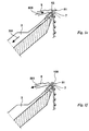
- Fig. La shows the front needle bed 1 and the rear needle bed 2 of a flat knitting machine.
- latch needles 3 and in the rear needle bed 2 also latch needles 4 are mounted longitudinally displaceable.
- transfer elements 5 and 6 are arranged for transferring stitches.
- the needle 3 holds a stitch 7 in its thread space 33, which is formed by needle hook 31 and the closed needle tongue 32.
- the transfer element 5 assigned to the needle 3 is part of a stitch transfer device 150, which is not shown in greater detail here.
- the transfer element 5 has a tip 51 with a breast surface 53.
- the needle 3 is in its home position, d. H. the mesh 7 is due to the action of the fabric take-off in the direction of the arrow 71 at the tee-off ground 11 of the front needle bed 1 at.
- the needle 3 is retracted in the direction of the arrow 301 until the loop 7 closes the tongue 32 when sliding forward on the needle 3 again and comes to lie on the closed tongue 32.
- This position is shown in FIG. 1d.
- the needle 3 has been withdrawn in the direction of the arrow 301 so far that the stitch is just before its knock-off position (transfer position).
- the mesh 7 is now through the needle head with the closed Tongue 32 stretched so far that the transfer element 5 can be expelled in the direction of arrow 500 and pushed into the mesh 7.
- the tip 51 of the transfer element 5 thereby slides laterally past the back of the tongue 32 and into the thread space 33 (FIG. 1 a) of the needle 3 so far that it protrudes on the inside of the legs of the loop 7.
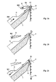
- the needle 3 is withdrawn in the direction of arrow 301 in its basic position and thereby the mesh 7 released (Fig le).
- the transfer element 5 is driven so far in the direction of the arrow 500 until the loop 7 rests against the chest area 53.
- the mesh 7 has now been taken over by the transfer element 5.
- the stitch transfer element 5 can be withdrawn in the direction of arrow 501 so that the loop 7 continues to hang on the tip 51, but the tip 51 hangs behind the center axis 100 the knitting machine is located.
- the transfer element 5 can be displaced laterally over the needle 3 by half a pitch, so that the needle 3 can continue to participate in the knitting process without the loop 7 located on the transfer element 5 hindering the knitting process (FIG. 1f).
- Figs. 2, 3 and 4 now show the transfer of the stitch 7 hanging on the transfer element 5 onto the same needle 3 or another needle of the same needle bed 1 (Fig. 2), onto the needle 4 of the opposite needle bed 2 (Fig. 3) and on an opposite transfer element 6 ( Figure 4).
- the stitch transfer element 5 has been driven in the direction of the arrow 500 in its transfer position for needles 3 of the same needle bed 1.
- the needle 3 is driven so far in the direction of the arrow 300 until the needle hook 31 in the mesh transfer element 5 is immersed in the region 52 and thus is in the region of the tip 51.
- the needle hook 31 slides through the legs of the mesh 7 therethrough.
- the stitch transfer element 5 is subsequently completely withdrawn in the direction of the arrow 501, so that the loop 7 now hangs on the needle 3.
- the needle 3 moves in the direction of arrow 301 back to its basic position, so that the loop 7 hangs in the needle hook 31 and abuts the tee-off ground 11 (Fig. 2c).
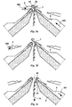
- the needle 4 according to FIG. 3 a is driven in the direction of the arrow 400 so far that it dives with its needle hook 41 into a section 52 of the stitch transfer element 5 which extends in the transfer position for needles of the opposite needle bed.
- the needle hook 41 also slides through the legs of the loop 7.
- the transfer element 5 is retracted in the direction of the arrow 501 so that the loop 7 now hangs solely on the needle 4.
- the needle 4 is subsequently retracted (FIG. 3 c) in the direction of the arrow 401 into its basic position so that the stitch 7 rests against the bottom of the rear needle bed 2.
- both transfer elements 5 and 6 are driven in the direction of the arrows 500 and 600 as far as shown in FIG. 4 so that the stitch transfer element 6 penetrates the section 52 of the stitch transfer element 5 dips and thereby passes with its tip 61 through the legs of the mesh 7.
- the stitch transfer element 5 is completely withdrawn in the direction of the arrow 501, so that the loop 7 now hangs solely on the transfer element 6.
- the transfer element 6 can then be withdrawn so far in the direction of the arrow 601 are that the mesh 7 while still hanging on the top 61, the tip 61 but is located behind the central axis 100 of the knitting machine.
- the needle 4 which is associated with the transfer element 6, take part in the further knitting process, but the loop 7 is held on the transfer element 6 for some time, then the needles 4 and the transfer element 6 can be offset from one another by half a pitch, so that the stitch 7 the Austriebsraum the needle 4 is free.
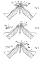
- Fig. 5 illustrates the acquisition of the mesh 7 of a needle 35.
- the slider 35 of the needle 30 and thus also the thread space 36 are closed.
- the needle 30 has been retracted so far in the direction of arrow 331 that it is in the transfer position, d. H. the mesh 7 rests on the closed slide 35.
- the transfer element 5 has been driven so far in the direction of the arrow 500 that its tip 51 pierces into the thread space 36 and thus between the legs of the stitch 7.
- Fig. 6 shows a further variant of the acquisition of a stitch 7 through the stitch transfer element 5 for latch needles 3.
- the needle 3 is driven in the direction of arrow 300 in its stitch transfer position in which the stitch 7 now comes to rest on the open tongue 32. Also in this position, the mesh 7 is stretched.
- a space is formed between the open tongue spoon 32 and the needle shaft.
- the transfer element 5 has been driven in the direction of arrow 500 with its tip 51. The tip 51 thus now pierces between the legs of the mesh 7 and thus can take over the stitch.
- FIGS. 7a, 7b and 8 illustrate a preferred embodiment of a transfer element 5.
- FIG. 7a shows the side view and
- FIG. 7b shows the top view of the transfer element 5.
- FIG. 7b illustrates that the tip 51 of the transfer element 5 is actually a double tip of two Leaf spring elements 51 and 51 'is.
- the leaf spring elements 51 and 51 ' abut each other. In their rear area, they enclose a cavity 52 into which the needle head of a needle 3, 4 can dip in order to take over the loop 7 hanging on the transfer element 5.
- the mesh 7 is supported after the acquisition.
- the transfer element 5 also has a solid shaft 54 which can be longitudinally slidably guided in a groove of a bar, not shown, and driven by a control cam.
- Fig. 8 illustrates in perspective view the acquisition of the mesh 7 of the needle 3 by the transfer element 5.
- the tip 51, 51 'of the transfer element 5 protrudes into the thread space of the needle 3 inside.
Claims (10)
- Procédé pour transporter des mailles (7) sur une machine à tricoter à l'aide d'éléments de transfert (5, 6), d'après lequel un élément de transfert (5, 6) est associé à toutes les aiguilles (3, 4, 30) à partir desquelles on doit transporter des mailles (7), les mailles (7) à transporter et maintenues dans l'aiguille (3, 4, 30) sont placées sur le clapet d'aiguille (32) ou sur le pousse-aiguille s'il s'agit d'aiguilles glissantes (30) par des mouvements d'expulsion de l'aiguille et/ou des mouvements de retrait tels qu'ils sont nécessaires à une opération normale de formation des mailles sans expulser plus loin les aiguilles qui transmettent des mailles,
caractérisé en ce qu'ensuite la pointe de l'élément de transfert (5, 6) qui peut se déplacer en sens longitudinal est insérée dans l'espace du fil (33, 36) et est introduite dans la maille (7) par l'avancée de l'élément de transfert (5, 6) et ensuite l'aiguille (3, 4, 30) est retirée de la maille (7) de sorte que seule la maille (7) est accrochée sur l'élément de transfert (5, 6) et est disponible pour la remettre à la même aiguille (3, 4, 30) ou à une autre aiguille ou à un autre élément de transfert (5, 6). - Procédé selon la revendication 1, caractérisé en ce que la maille (7) est placée sur le clapet (32) fermé de l'aiguille (3) par un mouvement d'avance de l'aiguille et par un mouvement ultérieur de retrait de l'aiguille.
- Procédé selon la revendication 1, caractérisé en ce que la maille (7) est placée sur le clapet (32) ouvert de l'aiguille (3) par un mouvement d'avance de l'aiguille.
- Procédé selon la revendication 1, caractérisé en ce que si on utilise des aiguilles glissantes (30) la maille (7) est placée sur le pousse-aiguille (35) fermé par un mouvement d'avance de l'aiguille alors que le pousse-aiguille (35) est ouvert et par un mouvement ultérieur de retrait de l'aiguille alors que le pousse-aiguille (35) est fermé.
- Dispositif transporteur de mailles pour une machine à tricoter rectiligne munie d'au moins une fonture (1, 2) afin d'exécuter le procédé selon l'une des revendications 1 à 4, comportant d'une part des aiguilles à clapet ou des aiguilles glissantes (3, 4, 30) à partir desquelles doivent être transportées des mailles (7) à chacune desquelles est associé un élément de transfert (5, 6) et d'autre part des cames de commande pour les aiguilles (3, 4, 30), dans ce dispositif les cames de commande pour les aiguilles (3, 4, 30) sont conçues de telle manière que les mailles (7) à transporter et maintenues dans l'aiguille (3, 4, 30) sont placées sur le clapet d'aiguille (32) ou sur le pousse-aiguille s'il s'agit d'aiguilles glissantes (30) par des mouvements d'expulsion de l'aiguille et/ou des mouvements de retrait tels qu'ils sont nécessaires à une opération normale de formation des mailles sans expulser plus loin les aiguilles qui transmettent des mailles, les éléments de transfert (5, 6) sont montés pour pouvoir se déplacer en sens longitudinal dans au moins une barre placée au-dessus de l'au moins une fonture (1, 2) et un entraînement est prévu pour les éléments de transfert (5, 6), caractérisé en ce que l'entraînement des éléments de transfert (5, 6) est conçu de telle manière qu'ensuite la pointe de l'élément de transfert (5, 6) est introduite dans la maille (7) par l'avancée de l'élément de transfert (5, 6) et que les cames de commande des aiguilles sont conçues de telle manière que les aiguilles (3, 4, 30) sont retirées de la maille (7), de sorte que la maille (7) seule est accrochée sur l'élément de transfert (5, 6) et qu'elle est disponible pour être remise à la même aiguille (3, 4, 30) ou à une autre aiguille ou à un d'autre élément de transfert (5, 6) et que les éléments de transfert (5, 6) comportent une pointe formée par au moins un ressort à lames (51, 51') qui peut être insérée dans l'espace de fil (33, 36).
- Dispositif selon la revendication 5, caractérisé en ce que l'au moins une barre est munie de rainures dans lesquelles les éléments de transfert (5, 6) sont montés pour pouvoir se déplacer en sens longitudinal, les éléments de transfert (5, 6) ayant le même écart mutuel que les aiguilles (3, 4, 30) de l'au moins une fonture (1, 2).
- Dispositif selon la revendication 5 ou 6, caractérisé en ce que l'au moins une barre est montée dans la machine à tricoter pour pouvoir se déplacer en sens longitudinal.
- Dispositif selon l'une des revendications 5 à 7, caractérisé en ce qu'au moins une barre équipée d'éléments de transfert (5, 6) est prévue pour chaque fonture (1, 2) de la machine à tricoter rectiligne.
- Dispositif selon l'une des revendications 5 à 8, caractérisé en ce que les éléments de transfert (5, 6) peuvent être commandés par des cames de commande dans lesquelles pénètrent des saillies situées sur les éléments de transfert (5, 6).
- Dispositif selon la revendication 9, caractérisé en ce que les cames de commande sont placées sur le ou les chariots pour commander les aiguilles de la machine à tricoter rectiligne.
Applications Claiming Priority (2)
| Application Number | Priority Date | Filing Date | Title |
|---|---|---|---|
| DE19954477A DE19954477A1 (de) | 1999-11-12 | 1999-11-12 | Verfahren und Vorrichtung zum Umhängen von Maschen auf einer Strickmaschine |
| DE19954477 | 1999-11-12 |
Publications (3)
| Publication Number | Publication Date |
|---|---|
| EP1099786A2 EP1099786A2 (fr) | 2001-05-16 |
| EP1099786A3 EP1099786A3 (fr) | 2002-07-03 |
| EP1099786B1 true EP1099786B1 (fr) | 2007-08-15 |
Family
ID=7928821
Family Applications (1)
| Application Number | Title | Priority Date | Filing Date |
|---|---|---|---|
| EP00123699A Expired - Lifetime EP1099786B1 (fr) | 1999-11-12 | 2000-10-31 | Procédé et dispositif pour reporter des mailles dans un métier à tricoter |
Country Status (6)
| Country | Link |
|---|---|
| US (1) | US6381992B1 (fr) |
| EP (1) | EP1099786B1 (fr) |
| JP (1) | JP3870332B2 (fr) |
| CN (1) | CN1195912C (fr) |
| DE (2) | DE19954477A1 (fr) |
| ES (1) | ES2288827T3 (fr) |
Families Citing this family (9)
| Publication number | Priority date | Publication date | Assignee | Title |
|---|---|---|---|---|
| TW575705B (en) * | 2000-03-30 | 2004-02-11 | Shima Seiki Mfg | Weft knitting machine with transferring mechanism and transferring method |
| TW584684B (en) * | 2000-05-18 | 2004-04-21 | Shima Seiki Mfg | Weft knitting machine with transfer mechanism |
| EP1616982B1 (fr) * | 2004-07-14 | 2008-07-23 | Groz-Beckert KG | Système pour la formation de maille et un élément pour un tel système |
| CN100485105C (zh) * | 2004-11-26 | 2009-05-06 | H.斯托尔两合公司 | 用于针织机的移圈针 |
| CN100500968C (zh) * | 2004-11-26 | 2009-06-17 | H.斯托尔两合公司 | 在针织机的移圈针上的部件的固定装置 |
| FR2986242B1 (fr) * | 2012-01-26 | 2014-02-14 | Steiger Participations Sa | Procede de tricotage pour machine a tricoter rectiligne et machine a tricoter rectiligne |
| CN105133168B (zh) * | 2014-06-09 | 2017-12-12 | 冯加林 | 一种横编织机 |
| CN109056176A (zh) * | 2018-10-11 | 2018-12-21 | 宁波慈星股份有限公司 | 针织横机中的移圈针 |
| CN109056177A (zh) * | 2018-10-11 | 2018-12-21 | 宁波慈星股份有限公司 | 横编机中的移圈针 |
Citations (3)
| Publication number | Priority date | Publication date | Assignee | Title |
|---|---|---|---|---|
| GB1110695A (en) * | 1964-07-22 | 1968-04-24 | Erba Maschb Ag | A stitch transfer device for hand knitting machines |
| DE1635965A1 (de) * | 1963-12-23 | 1973-04-12 | Schieber Universal Maschf | Einrichtung zum umhaengen von maschen von einer nadel zur nachbarnadel des gleichen nadelbettes |
| SU1652401A1 (ru) * | 1989-04-03 | 1991-05-30 | Ленинградское Специальное Конструкторское Бюро По Проектированию Трикотажных Машин | Движкова игла дл переноса петель на трикотажной машине |
Family Cites Families (17)
| Publication number | Priority date | Publication date | Assignee | Title |
|---|---|---|---|---|
| DE687091C (de) * | 1937-12-19 | 1940-01-22 | Walter & Co | Jacquard-Flachstrickmaschine zur selbsttaetigen Herstellung von einbettiger Petinetstrickware |
| DE705199C (de) * | 1939-01-22 | 1941-04-19 | Reutlinger Strickmaschinenfabr | Strickmaschine, insbesondere Flachstrickmaschine, zum UEberhaengen von Maschen |
| DE1773828U (de) * | 1957-02-20 | 1958-09-11 | Stoll & Co Strickmaschinenfabr | Vorrichtung zur selbsttaetigen herstellung von strickstuecken mit veraenderlicher breite auf flachstrickmaschinen. |
| BE793454A (fr) * | 1972-07-20 | 1973-04-16 | Abril Cullell | Perfectionnements apportes aux mecanismes de transfert lateral automatique des mailles dans les machines a tricoter |
| EP0103033A1 (fr) * | 1982-09-09 | 1984-03-21 | COMET MARTINELLI S.r.l. | Dispositif pour reporter des mailles d'aiguilles à des métiers rectilignes |
| DE3327093C2 (de) * | 1983-07-27 | 1986-05-22 | Universal Maschinenfabrik Dr. Rudolf Schieber GmbH & Co KG, 7081 Westhausen | Kombiniertes Strick-Umhhängeschloß für R-R-Flachstrickmaschinen mit V-förmig angeordneten Nadelbetten und mit Schiebernadeln |
| IT1208272B (it) * | 1987-04-10 | 1989-06-12 | Martinelli Comet Srl | Apparato di trasporto laterale per le macchine rettilinee da maglieria |
| US5305619A (en) * | 1990-03-26 | 1994-04-26 | Shima Seiki Mfg. Ltd. | Stitch increasing method and cams for flat knitting machine having stitch increasing function |
| JP2700203B2 (ja) * | 1991-10-04 | 1998-01-19 | 株式会社島精機製作所 | 横編機におけるトランスファーの方法およびその装置 |
| JP2794144B2 (ja) * | 1992-10-22 | 1998-09-03 | 株式会社島精機製作所 | 目移し装置を有する横編機 |
| JP3498270B2 (ja) * | 1994-04-28 | 2004-02-16 | 株式会社島精機製作所 | 横編機における糸案内方法及び装置 |
| DE4437583C1 (de) * | 1994-10-20 | 1996-03-21 | Schieber Universal Maschf | Flachstrickmaschine |
| US6047569A (en) * | 1997-05-27 | 2000-04-11 | Shima Seiki Manufacturing, Ltd. | Method for holding a stitch loop |
| US6018966A (en) * | 1997-07-11 | 2000-02-01 | Shima Seiki Manufacturing, Ltd. | Stitch forming method and a flat knitting machine therefor |
| JP3408735B2 (ja) * | 1997-12-19 | 2003-05-19 | 株式会社島精機製作所 | トランスファージャック目移し機構を備えた横編機 |
| JP2995464B2 (ja) * | 1998-05-15 | 1999-12-27 | 株式会社島精機製作所 | 横編機における編目ループの預け置き装置 |
| JP3158109B2 (ja) * | 1999-02-12 | 2001-04-23 | 株式会社島精機製作所 | 横編機による編目係止方法 |
-
1999
- 1999-11-12 DE DE19954477A patent/DE19954477A1/de not_active Withdrawn
-
2000
- 2000-10-31 EP EP00123699A patent/EP1099786B1/fr not_active Expired - Lifetime
- 2000-10-31 DE DE50014566T patent/DE50014566D1/de not_active Expired - Lifetime
- 2000-10-31 ES ES00123699T patent/ES2288827T3/es not_active Expired - Lifetime
- 2000-11-07 US US09/707,533 patent/US6381992B1/en not_active Expired - Fee Related
- 2000-11-08 JP JP2000378135A patent/JP3870332B2/ja not_active Expired - Fee Related
- 2000-11-11 CN CN00135522.8A patent/CN1195912C/zh not_active Expired - Lifetime
Patent Citations (3)
| Publication number | Priority date | Publication date | Assignee | Title |
|---|---|---|---|---|
| DE1635965A1 (de) * | 1963-12-23 | 1973-04-12 | Schieber Universal Maschf | Einrichtung zum umhaengen von maschen von einer nadel zur nachbarnadel des gleichen nadelbettes |
| GB1110695A (en) * | 1964-07-22 | 1968-04-24 | Erba Maschb Ag | A stitch transfer device for hand knitting machines |
| SU1652401A1 (ru) * | 1989-04-03 | 1991-05-30 | Ленинградское Специальное Конструкторское Бюро По Проектированию Трикотажных Машин | Движкова игла дл переноса петель на трикотажной машине |
Also Published As
| Publication number | Publication date |
|---|---|
| CN1296091A (zh) | 2001-05-23 |
| JP3870332B2 (ja) | 2007-01-17 |
| EP1099786A3 (fr) | 2002-07-03 |
| JP2001200453A (ja) | 2001-07-27 |
| EP1099786A2 (fr) | 2001-05-16 |
| ES2288827T3 (es) | 2008-02-01 |
| DE19954477A1 (de) | 2001-06-07 |
| CN1195912C (zh) | 2005-04-06 |
| DE50014566D1 (de) | 2007-09-27 |
| US6381992B1 (en) | 2002-05-07 |
Similar Documents
| Publication | Publication Date | Title |
|---|---|---|
| EP1099786B1 (fr) | Procédé et dispositif pour reporter des mailles dans un métier à tricoter | |
| WO2009092352A2 (fr) | Textile à côtes 1/1, procédé et machine à tricoter appropriés pour le produire | |
| EP1321552B1 (fr) | Aiguille pour métiers à mailles cueillies ou mailles jetées et machine à tricoter équipé avec celle-ci | |
| DE2909963C2 (de) | Verfahren zur maschinellen Maschenbildung | |
| DE10335464B4 (de) | Verfahren zum maschinellen Maschenbilden mit zugehörigen Maschenbildungselementen | |
| DE102010017946B4 (de) | Schlosssystem für eine Flachstrickmaschine | |
| EP1522617B1 (fr) | Métier à tricoter rectiligne comprenant au moins une fonture | |
| EP1262585A1 (fr) | Procédé pour retenir des boucles | |
| EP1757721B1 (fr) | Aiguille de transfert et méthode pour le transfert de maille | |
| EP2666896B1 (fr) | Machine à tricoter rectiligne dotée d'éléments de découpe | |
| DE3928986C2 (de) | Strickmaschine | |
| EP0179072B1 (fr) | Procede de fabrication d'un tissu a motifs tricote en chaine et metier chaine pour sa mise en o euvre | |
| DE1635861B2 (de) | Mehrsystemige doppelzylinder-rundstrickmaschine mit mustereinrichtung zur herstellung gemusterter links/linksgestricke | |
| DE2853819C2 (de) | Links + Links-Flachstrickmaschine | |
| DE4437583C1 (de) | Flachstrickmaschine | |
| EP1464746B1 (fr) | Aiguille pour métiers à tricoter et procédé pour la partition d'une maille | |
| DD145117A1 (de) | Strickmaschine,insbesondere flachs rickmaschine | |
| DE19508756A1 (de) | Flachstrickmaschine | |
| DE3629791C2 (fr) | ||
| DE2130130B2 (de) | Raschelmaschine mit einer Ein richtung zur Legung von Schußfaden | |
| DE1560935C (de) | Rundstrickmaschine | |
| DE2414890C2 (de) | Verfahren und Flachstrickmaschine zum Herstellen eines Strickrandes und Vereinigen des Strickrandes mit einem Warenteil | |
| AT214041B (de) | Verfahren zur Herstellung laufmaschenfester Strickware und Vorrichtung zur Durchführung desselben | |
| DE170736C (fr) | ||
| DE586101C (de) | Verfahren und Vorrichtung zur Herstellung von Filetware auf flachen Kulierwirkmaschinen |
Legal Events
| Date | Code | Title | Description |
|---|---|---|---|
| PUAI | Public reference made under article 153(3) epc to a published international application that has entered the european phase |
Free format text: ORIGINAL CODE: 0009012 |
|
| AK | Designated contracting states |
Kind code of ref document: A2 Designated state(s): AT BE CH CY DE DK ES FI FR GB GR IE IT LI LU MC NL PT SE |
|
| AX | Request for extension of the european patent |
Free format text: AL;LT;LV;MK;RO;SI |
|
| PUAL | Search report despatched |
Free format text: ORIGINAL CODE: 0009013 |
|
| AK | Designated contracting states |
Kind code of ref document: A3 Designated state(s): AT BE CH CY DE DK ES FI FR GB GR IE IT LI LU MC NL PT SE |
|
| AX | Request for extension of the european patent |
Free format text: AL;LT;LV;MK;RO;SI |
|
| 17P | Request for examination filed |
Effective date: 20021214 |
|
| AKX | Designation fees paid |
Designated state(s): DE ES IT |
|
| 17Q | First examination report despatched |
Effective date: 20040802 |
|
| GRAP | Despatch of communication of intention to grant a patent |
Free format text: ORIGINAL CODE: EPIDOSNIGR1 |
|
| GRAS | Grant fee paid |
Free format text: ORIGINAL CODE: EPIDOSNIGR3 |
|
| GRAA | (expected) grant |
Free format text: ORIGINAL CODE: 0009210 |
|
| AK | Designated contracting states |
Kind code of ref document: B1 Designated state(s): DE ES IT |
|
| REF | Corresponds to: |
Ref document number: 50014566 Country of ref document: DE Date of ref document: 20070927 Kind code of ref document: P |
|
| REG | Reference to a national code |
Ref country code: ES Ref legal event code: FG2A Ref document number: 2288827 Country of ref document: ES Kind code of ref document: T3 |
|
| PLBE | No opposition filed within time limit |
Free format text: ORIGINAL CODE: 0009261 |
|
| STAA | Information on the status of an ep patent application or granted ep patent |
Free format text: STATUS: NO OPPOSITION FILED WITHIN TIME LIMIT |
|
| 26N | No opposition filed |
Effective date: 20080516 |
|
| PGFP | Annual fee paid to national office [announced via postgrant information from national office to epo] |
Ref country code: ES Payment date: 20081029 Year of fee payment: 9 |
|
| PGFP | Annual fee paid to national office [announced via postgrant information from national office to epo] |
Ref country code: IT Payment date: 20091005 Year of fee payment: 10 |
|
| PGFP | Annual fee paid to national office [announced via postgrant information from national office to epo] |
Ref country code: DE Payment date: 20101102 Year of fee payment: 11 |
|
| REG | Reference to a national code |
Ref country code: ES Ref legal event code: FD2A Effective date: 20110325 |
|
| PG25 | Lapsed in a contracting state [announced via postgrant information from national office to epo] |
Ref country code: ES Free format text: LAPSE BECAUSE OF NON-PAYMENT OF DUE FEES Effective date: 20110314 |
|
| PG25 | Lapsed in a contracting state [announced via postgrant information from national office to epo] |
Ref country code: ES Free format text: LAPSE BECAUSE OF NON-PAYMENT OF DUE FEES Effective date: 20091101 |
|
| PG25 | Lapsed in a contracting state [announced via postgrant information from national office to epo] |
Ref country code: IT Free format text: LAPSE BECAUSE OF NON-PAYMENT OF DUE FEES Effective date: 20101031 |
|
| PG25 | Lapsed in a contracting state [announced via postgrant information from national office to epo] |
Ref country code: DE Free format text: LAPSE BECAUSE OF NON-PAYMENT OF DUE FEES Effective date: 20120501 |
|
| REG | Reference to a national code |
Ref country code: DE Ref legal event code: R119 Ref document number: 50014566 Country of ref document: DE Effective date: 20120501 |