EP1099786B1 - Method and device for transfering stitches on a knitting machine - Google Patents
Method and device for transfering stitches on a knitting machine Download PDFInfo
- Publication number
- EP1099786B1 EP1099786B1 EP00123699A EP00123699A EP1099786B1 EP 1099786 B1 EP1099786 B1 EP 1099786B1 EP 00123699 A EP00123699 A EP 00123699A EP 00123699 A EP00123699 A EP 00123699A EP 1099786 B1 EP1099786 B1 EP 1099786B1
- Authority
- EP
- European Patent Office
- Prior art keywords
- needle
- stitch
- transfer
- transfer element
- needles
- Prior art date
- Legal status (The legal status is an assumption and is not a legal conclusion. Google has not performed a legal analysis and makes no representation as to the accuracy of the status listed.)
- Expired - Lifetime
Links
- 238000009940 knitting Methods 0.000 title claims description 34
- 238000000034 method Methods 0.000 title claims description 27
- 230000015572 biosynthetic process Effects 0.000 claims 2
- 210000000038 chest Anatomy 0.000 description 2
- 239000004744 fabric Substances 0.000 description 2
- 238000004519 manufacturing process Methods 0.000 description 2
- 230000005540 biological transmission Effects 0.000 description 1
- 210000000481 breast Anatomy 0.000 description 1
- 238000006073 displacement reaction Methods 0.000 description 1
- 238000009944 hand knitting Methods 0.000 description 1
- 238000003780 insertion Methods 0.000 description 1
- 230000037431 insertion Effects 0.000 description 1
- 239000007787 solid Substances 0.000 description 1
Images


Classifications
-
- D—TEXTILES; PAPER
- D04—BRAIDING; LACE-MAKING; KNITTING; TRIMMINGS; NON-WOVEN FABRICS
- D04B—KNITTING
- D04B1/00—Weft knitting processes for the production of fabrics or articles not dependent on the use of particular machines; Fabrics or articles defined by such processes
- D04B1/22—Weft knitting processes for the production of fabrics or articles not dependent on the use of particular machines; Fabrics or articles defined by such processes specially adapted for knitting goods of particular configuration
-
- D—TEXTILES; PAPER
- D04—BRAIDING; LACE-MAKING; KNITTING; TRIMMINGS; NON-WOVEN FABRICS
- D04B—KNITTING
- D04B15/00—Details of, or auxiliary devices incorporated in, weft knitting machines, restricted to machines of this kind
- D04B15/02—Loop-transfer points
Definitions
- the present invention relates to a method for transferring stitches on a knitting machine by means of transfer elements and a stitching device for a flat knitting machine and at least one needle bed for carrying out the method.
- a hand-operated cover device for hand knitting apparatuses which has a plurality of rigidly arranged transmission members with which lying on the needle tongue mesh can be taken.
- the present invention has for its object to provide a method and apparatus for transferring stitches, which avoids a higher yarn load and an increase in the production times of the knitted fabric.
- the stitch can be placed on the closed tongue of the needle by a needle advancing and then needle retraction movement. It is sufficient that the needle is driven so far only that the mesh is behind the open tongue. However, the stitch may also be placed on the open tongue of the needle by a needle advancing movement. Both with open and closed tongue, the mesh is stretched enough to pierce the transfer element in the mesh can.
- the stitch can be placed over the closed slider by a needle advancing movement with the slider open, followed by a needle retraction movement with the slider closed. It then results in similar conditions for the Um feelingvorgang as when placing the stitch on the closed tongue of a latch needle.
- the method according to the invention can be applied both to flat knitting machines and to circular knitting machines.
- the Maschenum suvoroplasty invention has the features of claim 5. With this Blattfeder dictate it is possible to stab into the held on the tongue or the slide mesh. The leaf spring dips into the thread space of the needle and moves between the legs of the stitch ...
- the transfer elements may comprise a tip formed by two leaf springs, one leaf spring being slidable over the left side and the other leaf spring slidable over the right side of the needle tongue or needle pusher and insertable between the loop legs.
- the mesh is detected symmetrically on the left and right of the needle shaft, whereby the acquisition of the mesh on the transfer element is even safer.
- the two leaf spring elements spring together and together form the tip of the transfer element.
- the transfer elements can be longitudinally displaceably mounted in at least one bar arranged above the at least one needle bed of the flat knitting machine.
- the at least one bar can be provided with grooves in which the transfer elements are mounted longitudinally displaceable, wherein the transfer elements have the same mutual distance as the needles of the at least one needle bed. This ensures that each needle is assigned a transfer element exactly.
- the at least one needle bed of the flat knitting machine is not mounted longitudinally displaceable, the at least one bar can be mounted longitudinally displaceable on the knitting machine. As a result, a lateral displacement of the stitches is possible by the transfer operation.
- the bars with the transfer elements can also be fixedly arranged.
- the barre can be provided over its entire length with transfer elements or even only in sections.
- the transfer elements can preferably be controlled by control cams, similar to the needles of the flat knitting machine, in which projections arranged on the transfer elements engage. It is expedient if these cams are arranged on the carriage or carriages for needle control of the flat knitting machine. There is then no separate drive for the selection of the transfer elements required.
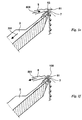
- Fig. La shows the front needle bed 1 and the rear needle bed 2 of a flat knitting machine.
- latch needles 3 and in the rear needle bed 2 also latch needles 4 are mounted longitudinally displaceable.
- transfer elements 5 and 6 are arranged for transferring stitches.
- the needle 3 holds a stitch 7 in its thread space 33, which is formed by needle hook 31 and the closed needle tongue 32.
- the transfer element 5 assigned to the needle 3 is part of a stitch transfer device 150, which is not shown in greater detail here.
- the transfer element 5 has a tip 51 with a breast surface 53.
- the needle 3 is in its home position, d. H. the mesh 7 is due to the action of the fabric take-off in the direction of the arrow 71 at the tee-off ground 11 of the front needle bed 1 at.
- the needle 3 is retracted in the direction of the arrow 301 until the loop 7 closes the tongue 32 when sliding forward on the needle 3 again and comes to lie on the closed tongue 32.
- This position is shown in FIG. 1d.
- the needle 3 has been withdrawn in the direction of the arrow 301 so far that the stitch is just before its knock-off position (transfer position).
- the mesh 7 is now through the needle head with the closed Tongue 32 stretched so far that the transfer element 5 can be expelled in the direction of arrow 500 and pushed into the mesh 7.
- the tip 51 of the transfer element 5 thereby slides laterally past the back of the tongue 32 and into the thread space 33 (FIG. 1 a) of the needle 3 so far that it protrudes on the inside of the legs of the loop 7.
- the needle 3 is withdrawn in the direction of arrow 301 in its basic position and thereby the mesh 7 released (Fig le).
- the transfer element 5 is driven so far in the direction of the arrow 500 until the loop 7 rests against the chest area 53.
- the mesh 7 has now been taken over by the transfer element 5.
- the stitch transfer element 5 can be withdrawn in the direction of arrow 501 so that the loop 7 continues to hang on the tip 51, but the tip 51 hangs behind the center axis 100 the knitting machine is located.
- the transfer element 5 can be displaced laterally over the needle 3 by half a pitch, so that the needle 3 can continue to participate in the knitting process without the loop 7 located on the transfer element 5 hindering the knitting process (FIG. 1f).
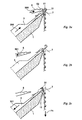
- Figs. 2, 3 and 4 now show the transfer of the stitch 7 hanging on the transfer element 5 onto the same needle 3 or another needle of the same needle bed 1 (Fig. 2), onto the needle 4 of the opposite needle bed 2 (Fig. 3) and on an opposite transfer element 6 ( Figure 4).
- the stitch transfer element 5 has been driven in the direction of the arrow 500 in its transfer position for needles 3 of the same needle bed 1.
- the needle 3 is driven so far in the direction of the arrow 300 until the needle hook 31 in the mesh transfer element 5 is immersed in the region 52 and thus is in the region of the tip 51.
- the needle hook 31 slides through the legs of the mesh 7 therethrough.
- the stitch transfer element 5 is subsequently completely withdrawn in the direction of the arrow 501, so that the loop 7 now hangs on the needle 3.
- the needle 3 moves in the direction of arrow 301 back to its basic position, so that the loop 7 hangs in the needle hook 31 and abuts the tee-off ground 11 (Fig. 2c).
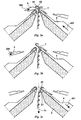
- the needle 4 according to FIG. 3 a is driven in the direction of the arrow 400 so far that it dives with its needle hook 41 into a section 52 of the stitch transfer element 5 which extends in the transfer position for needles of the opposite needle bed.
- the needle hook 41 also slides through the legs of the loop 7.
- the transfer element 5 is retracted in the direction of the arrow 501 so that the loop 7 now hangs solely on the needle 4.
- the needle 4 is subsequently retracted (FIG. 3 c) in the direction of the arrow 401 into its basic position so that the stitch 7 rests against the bottom of the rear needle bed 2.
- both transfer elements 5 and 6 are driven in the direction of the arrows 500 and 600 as far as shown in FIG. 4 so that the stitch transfer element 6 penetrates the section 52 of the stitch transfer element 5 dips and thereby passes with its tip 61 through the legs of the mesh 7.
- the stitch transfer element 5 is completely withdrawn in the direction of the arrow 501, so that the loop 7 now hangs solely on the transfer element 6.
- the transfer element 6 can then be withdrawn so far in the direction of the arrow 601 are that the mesh 7 while still hanging on the top 61, the tip 61 but is located behind the central axis 100 of the knitting machine.
- the needle 4 which is associated with the transfer element 6, take part in the further knitting process, but the loop 7 is held on the transfer element 6 for some time, then the needles 4 and the transfer element 6 can be offset from one another by half a pitch, so that the stitch 7 the Austriebsraum the needle 4 is free.
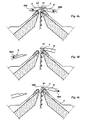
- Fig. 5 illustrates the acquisition of the mesh 7 of a needle 35.
- the slider 35 of the needle 30 and thus also the thread space 36 are closed.
- the needle 30 has been retracted so far in the direction of arrow 331 that it is in the transfer position, d. H. the mesh 7 rests on the closed slide 35.
- the transfer element 5 has been driven so far in the direction of the arrow 500 that its tip 51 pierces into the thread space 36 and thus between the legs of the stitch 7.
- Fig. 6 shows a further variant of the acquisition of a stitch 7 through the stitch transfer element 5 for latch needles 3.
- the needle 3 is driven in the direction of arrow 300 in its stitch transfer position in which the stitch 7 now comes to rest on the open tongue 32. Also in this position, the mesh 7 is stretched.
- a space is formed between the open tongue spoon 32 and the needle shaft.
- the transfer element 5 has been driven in the direction of arrow 500 with its tip 51. The tip 51 thus now pierces between the legs of the mesh 7 and thus can take over the stitch.
- FIGS. 7a, 7b and 8 illustrate a preferred embodiment of a transfer element 5.
- FIG. 7a shows the side view and
- FIG. 7b shows the top view of the transfer element 5.
- FIG. 7b illustrates that the tip 51 of the transfer element 5 is actually a double tip of two Leaf spring elements 51 and 51 'is.
- the leaf spring elements 51 and 51 ' abut each other. In their rear area, they enclose a cavity 52 into which the needle head of a needle 3, 4 can dip in order to take over the loop 7 hanging on the transfer element 5.
- the mesh 7 is supported after the acquisition.
- the transfer element 5 also has a solid shaft 54 which can be longitudinally slidably guided in a groove of a bar, not shown, and driven by a control cam.
- Fig. 8 illustrates in perspective view the acquisition of the mesh 7 of the needle 3 by the transfer element 5.
- the tip 51, 51 'of the transfer element 5 protrudes into the thread space of the needle 3 inside.
Landscapes
- Engineering & Computer Science (AREA)
- Textile Engineering (AREA)
- Knitting Machines (AREA)
Description
Die vorliegende Erfindung betrifft ein Verfahren zum Umhängen von Maschen auf einer Strickmaschine mittels Transferelementen und eine Maschenumhängevorrichtung für eine Flachstrickmaschine und mindestens einem Nadelbett zur Durchführung des Verfahrens.The present invention relates to a method for transferring stitches on a knitting machine by means of transfer elements and a stitching device for a flat knitting machine and at least one needle bed for carrying out the method.
Bei bekannten Verfahren zum Umhängen von Maschen werden die Nadeln, die die umzuhängenden Maschen halten, so weit ausgefahren, dass die Maschen über die geöffnete Zunge oder den Schieber der Nadel bis zu einem Absatz am Nadelschaft gleiten. Dort wird die Masche von einer Spreizfeder aufgespreizt, sodass sie anschließend von einer Nadel des gegenüberliegenden Nadelbetts oder aber auch von Umhängefingern aufgenommen werden kann. Solche Verfahren sind beispielsweise in der
Die bekannten Verfahren haben den Nachteil, dass ein großer Nadelaustrieb notwendig ist. Die dafür notwendigen Steuerkurven bedingen entsprechend breite Strickschlösser. Außerdem führt der weite Nadelaustrieb zu einer Reduktion der Produktionsgeschwindigkeit des Gestrickstücks.The known methods have the disadvantage that a large needle ejection is necessary. The necessary cams require correspondingly wide knitting locks. In addition, the wide Nadelaustrieb leads to a reduction in the production speed of the knitted piece.
Aus der
Der Hauptnachteil der bekannten Verfahren für Industrie-Strickmaschinen liegt jedoch darin, dass die Maschen vor der Übergabe an eine benachbarte Nadel oder einen Umhängefinger weit aus dem Maschenverbund herausgezogen und aufgespreizt werden, wodurch es bei empfindlichen Garnen zum Platzen der Masche kommen kann. Die umgehängten Maschen werden außerdem durch den Umhängevorgang vergrößert, was bei Glattgestricken im Gesamtgestrickbild sichtbar ist und somit die Qualität des Gestrickstücks einschränkt.The main drawback of the known methods for industrial knitting machines, however, is that the stitches are pulled out and spread far out of the stitching prior to transfer to an adjacent needle or cape finger, which can cause delicate stitches to burst the stitch. The stitched stitches are also increased by the Umhängevorgang, which is visible in smooth knit in Gesamtgestrickbild and thus limits the quality of the knitted piece.
Der vorliegenden Erfindung liegt die Aufgabe zugrunde, ein Verfahren und eine Vorrichtung zum Umhängen von Maschen vorzuschlagen, das eine höhere Garnbelastung und eine Erhöhung der Produktionszeiten des Gestricks vermeidet.The present invention has for its object to provide a method and apparatus for transferring stitches, which avoids a higher yarn load and an increase in the production times of the knitted fabric.
Die Aufgabe wird mit einem Verfahren mit dem Merkmalen des Anspruchs 1 gelöst.The object is achieved by a method having the features of
Zur Platzierung der Masche auf der Zunge oder dem Schieber sind höchstens Nadelbewegungen erforderlich, wie sie auch zum normalen Maschenbildungsvorgang nötig sind. Der bei den bekannten Verfahren übliche weitere Austrieb der die Masche übergebenden Nadel entfällt hier also. Dennoch wird auch beim erfindungsgemäßen Verfahren die Masche durch die Nadelzunge oder den Nadelschieber ausreichend gespannt, damit die Spitze des Transferelements in die Masche eingeführt werden kann. Es wird jedoch kein zusätzliches Aufspreizen der Masche im Vergleich zu den übrigen, nicht umgehängten Maschen vorgenommen, sodass es auch zu keiner nennenswerten Vergrößerung der umgehängten Maschen kommt, die später im Gestrickbild zu sehen wäre.For the placement of the stitch on the tongue or the slider needle movements are required at most, as they are also necessary for normal stitching process. The usual in the known methods further expulsion of the mesh transferring needle is omitted here so. Nevertheless, in the method according to the invention, too, the stitch is sufficiently tensioned by the needle tongue or the needle slider, so that the tip of the transfer element can be inserted into the stitch. It However, no additional spreading of the stitch is made in comparison to the other, not umgehängten stitches, so that there is no significant increase in the stitched stitches, which would be seen later in the knitted image.
Für die Platzierung der Masche gibt es unterschiedliche Möglichkeiten. Die Masche kann durch eine Nadelvortriebs- und anschließende Nadelrückzugsbewegung auf der geschlossenen Zunge der Nadel platziert werden. Dabei genügt es, dass die Nadel nur so weit vorgetrieben wird, dass die Masche hinter der geöffneten Zunge liegt. Die Masche kann jedoch auch durch eine Nadelvortriebsbewegung auf der geöffneten Zunge der Nadel platziert werden. Sowohl bei geöffneter als auch bei geschlossener Zunge wird die Masche genügend gespannt, um das Transferelement in die Masche einstechen zu können.For the placement of the mesh there are different possibilities. The stitch can be placed on the closed tongue of the needle by a needle advancing and then needle retraction movement. It is sufficient that the needle is driven so far only that the mesh is behind the open tongue. However, the stitch may also be placed on the open tongue of the needle by a needle advancing movement. Both with open and closed tongue, the mesh is stretched enough to pierce the transfer element in the mesh can.
Bei der Verwendung von Schiebernadeln kann die Masche durch eine Nadelvortriebsbewegung bei geöffnetem Schieber und einer anschließenden Nadelrückzugsbewegung bei geschlossenem Schieber über dem geschlossenen Schieber platziert werden. Es ergeben sich dann ähnliche Verhältnisse für den Umhängevorgang wie beim Platzieren der Masche auf der geschlossenen Zunge einer Zungennadel.When using slider needles, the stitch can be placed over the closed slider by a needle advancing movement with the slider open, followed by a needle retraction movement with the slider closed. It then results in similar conditions for the Umhängevorgang as when placing the stitch on the closed tongue of a latch needle.
Das erfindungsgemäße Verfahren lässt sich sowohl auf Flachstrickmaschinen als auch auf Rundstrickmaschinen anwenden.The method according to the invention can be applied both to flat knitting machines and to circular knitting machines.
Die erfindungsgemäße Maschenumhängevorrichtung weist die Merkmale des Anspruches 5 auf. Mit dieser Blattfederspitze ist es möglich, in die auf der Zunge oder dem Schieber gespannt gehaltene Masche einzustechen. Die Blattfeder taucht dabei in den Fadenraum der Nadel ein und fährt zwischen die Schenkel der Masche...The Maschenumhängevorrichtung invention has the features of
.,
Bei einer bevorzugten Ausführungsform können die Transferelemente eine von zwei Blattfedern gebildete Spitze aufweisen, wobei die eine Blattfeder über die linke Seite und die andere Blattfeder über die rechte Seite der Nadelzunge oder des Nadelschiebers schiebbar und zwischen die Maschenschenkel einführbar ist. Bei einer solchen Ausgestaltung der Spitze wird die Masche symmetrisch links und rechts des Nadelschafts erfasst, wodurch die Übernahme der Masche auf das Transferelement noch sicherer wird. Nach dem Rückzug der Nadel aus der Masche heraus federn die beiden Blattfederelemente zusammen und bilden gemeinsam die Spitze des Transferelements.In a preferred embodiment, the transfer elements may comprise a tip formed by two leaf springs, one leaf spring being slidable over the left side and the other leaf spring slidable over the right side of the needle tongue or needle pusher and insertable between the loop legs. In such an embodiment of the tip, the mesh is detected symmetrically on the left and right of the needle shaft, whereby the acquisition of the mesh on the transfer element is even safer. After the withdrawal of the needle out of the loop, the two leaf spring elements spring together and together form the tip of the transfer element.
Bei einer Umhängevorrichtung für eine Flachstrickmaschine können die Transferelemente in mindestens einer über dem mindestens einen Nadelbett der Flachstrickmaschine angeordneten Barre längs verschiebbar gelagert sein. Dazu kann die mindestens eine Barre mit Nuten versehen sein, in denen die Transferelemente längs verschiebbar gelagert sind, wobei die Transferelemente den gleichen gegenseitigen Abstand aufweisen wie die Nadeln des mindestens einen Nadelbetts. Dadurch ist gewährleistet, dass jeder Nadel ein Transferelement exakt zugeordnet wird.In a capping device for a flat knitting machine, the transfer elements can be longitudinally displaceably mounted in at least one bar arranged above the at least one needle bed of the flat knitting machine. For this purpose, the at least one bar can be provided with grooves in which the transfer elements are mounted longitudinally displaceable, wherein the transfer elements have the same mutual distance as the needles of the at least one needle bed. This ensures that each needle is assigned a transfer element exactly.
Falls das mindestens eine Nadelbett der Flachstrickmaschine nicht längs verschiebbar gelagert ist, kann die mindestens eine Barre längs verschiebbar an der Strickmaschine gelagert sein. Dadurch ist ein seitliches Versetzen der Maschen durch den Umhängevorgang möglich. Bei längs verschieblichen Nadelbetten können die Barren mit den Transferelementen auch fest angeordnet sein.If the at least one needle bed of the flat knitting machine is not mounted longitudinally displaceable, the at least one bar can be mounted longitudinally displaceable on the knitting machine. As a result, a lateral displacement of the stitches is possible by the transfer operation. In the case of longitudinally displaceable needle beds, the bars with the transfer elements can also be fixedly arranged.
Bei mehrbettigen Flachstrickmaschinen ist es vorteilhaft, wenn für jedes Nadelbett der Flachstrickmaschine mindestens eine Barre mit Transferelementen vorgesehen ist. Die Barre kann dabei über ihre ganze Länge mit Transferelementen versehen sein oder aber auch nur in Teilabschnitten. Außerdem ist es selbstverständlich möglich, für jedes Nadelbett mehrere Barren in denjenigen Bereichen vorzusehen, in denen Umhängevorgänge vorgenommen werden sollen.In multi-bed flat knitting machines, it is advantageous if at least one bar with transfer elements is provided for each needle bed of the flat knitting machine. The barre can be provided over its entire length with transfer elements or even only in sections. In addition, it is of course possible to provide for each needle bed several bars in those areas in which Umhängevorgänge should be made.
Die Transferelemente können vorzugsweise ähnlich wie die Nadeln der Flachstrickmaschine durch Steuerkurven ansteuerbar sein, in die an den Transferelementen angeordnete Vorsprünge eingreifen. Dabei ist es zweckmäßig, wenn diese Steuerkurven an dem oder den Schlitten zur Nadelansteuerung der Flachstrickmaschine angeordnet sind. Es ist dann kein separater Antrieb für die Auswahl der Transferelemente erforderlich.The transfer elements can preferably be controlled by control cams, similar to the needles of the flat knitting machine, in which projections arranged on the transfer elements engage. It is expedient if these cams are arranged on the carriage or carriages for needle control of the flat knitting machine. There is then no separate drive for the selection of the transfer elements required.
Nachfolgend werden anhand der Zeichnung Maschenumhängevorgänge nach dem erfindungsgemäßen Verfahren sowie eine bevorzugte Ausführungsform eines Transferelements einer erfindungsgemäßen Vorrichtung näher beschrieben.Hereinafter, looping operations according to the inventive method and a preferred embodiment of a transfer element of a device according to the invention will be described in more detail with reference to the drawing.
Es zeigen:
- Fig. 1a - 1f
- Teilquerschnitte durch das vordere und hintere Nadelbett einer Flachstrickmaschine mit einer erfindungsgemäßen Umhängevorrichtung mit unterschiedlichen Nadel- und Transferelementstellungen während der Übernahme einer Masche auf das Transferelement nach einem erfindungsgemäßen Verfahren;
- Fig. 2a - 2c
- einen Teilquerschnitt durch das vordere Nadelbett einer Flachstrickmaschine mit einer erfindungsgemäßen Umhängevorrichtung mit unterschiedlichen Nadelpositionen und Transferelementpositionen bei der Übergabe einer Masche auf eine Nadel des vorderen Nadelbetts;
- Fig. 3a - 3c
- Teilquerschnitte durch das vordere und hintere Nadelbett einer Flachstrickmaschine mit einer erfindungsgemäßen Umhängevorrichtung mit unterschiedlichen Nadel- und Transferelementpositionen während des Übergebens einer Masche auf eine Nadel des hinteren Nadelbetts;
- Fig. 4a - 4c
- Teilquerschnitte durch das vordere und hintere Nadelbett einer Flachstrickmaschine mit einer erfindungsgemäßen Umhängevorrichtung mit verschiedenen Transferelementpositionen während der Übergabe einer Masche von einem Transferelement auf ein anderes Transferelement;
- Fig. 5
- einen Teilquerschnitt durch das vordere Nadelbett einer Flachstrickmaschine mit Schiebernadeln und einer erfindungsgemäßen Umhängevorrichtung;
- Fig. 6
- einen Teilquerschnitt durch das vordere Nadelbett einer Flachstrickmaschine mit einer erfindungsgemäßen Umhängevorrichtung bei Übernahme einer auf einer geöffneten Zungennadel liegenden Masche auf ein Transferelement;
- Fig. 7a, 7b
- Detailansichten eines Transferelements;
- Fig. 8
- schematische perspektivische Darstellung der Maschenübernahme durch das Transferelement gemäß Fig. 7.
- Fig. 1a - 1f
- Partial cross sections through the front and rear needle bed of a flat knitting machine with a capping device according to the invention with different needle and transfer element positions during the acquisition of a stitch on the transfer element according to a method of the invention;
- Fig. 2a - 2c
- a partial cross section through the front needle bed of a flat knitting machine with a capping device according to the invention with different needle positions and transfer element positions in the transfer of a stitch on a needle of the front needle bed;
- Fig. 3a - 3c
- Partial cross sections through the front and rear needle bed of a flat knitting machine with a capping device according to the invention with different needle and transfer element positions during the transfer of a stitch to a needle of the rear needle bed;
- Fig. 4a - 4c
- Partial cross-sections through the front and rear needle bed of a flat knitting machine with a capping device according to the invention with different transfer element positions during the transfer of a stitch from one transfer element to another transfer element;
- Fig. 5
- a partial cross section through the front needle bed of a flat knitting machine with slide needles and a capping device according to the invention;
- Fig. 6
- a partial cross section through the front needle bed of a flat knitting machine with a capping device according to the invention upon adoption of a lying on an open latch needle mesh on a transfer element;
- Fig. 7a, 7b
- Detailed views of a transfer element;
- Fig. 8
- schematic perspective view of the mesh takeover by the transfer element according to FIG. 7.
Fig. la zeigt das vordere Nadelbett 1 und das hintere Nadelbett 2 einer Flachstrickmaschine. Im vorderen Nadelbett 1 sind Zungennadeln 3 und im hinteren Nadelbett 2 ebenfalls Zungennadeln 4 längs verschieblich gelagert. Über den Nadelbetten 1 und 2 mit den Nadeln 3 und 4 sind Transferelemente 5 und 6 zum Umhängen von Maschen angeordnet. Im dargestellten Beispiel hält die Nadel 3 eine Masche 7 in ihrem Fadenraum 33, der von Nadelhaken 31 sowie der geschlossenen Nadelzunge 32 gebildet wird. Das der Nadel 3 zugeordnete Transferelement 5 ist Teil einer Maschentransfervorrichtung 150, die hier nicht näher dargestellt ist. Das Transferelement 5 weist eine Spitze 51 mit einer Brustfläche 53 auf. In Fig. la befindet sich die Nadel 3 in ihrer Grundposition, d. h. die Masche 7 liegt durch die Wirkung des Gestrickabzugs in Richtung des Pfeils 71 am Abschlaggrund 11 des vorderen Nadelbetts 1 an.Fig. La shows the
In Fig. 1b ist die Nadel 3 in Richtung des Pfeils 300 ausgetrieben worden, sodass die Nadelzunge 32 durch die Masche 7 geöffnet wurde und sich die Masche 7 nun auf dem Nadelschaft hinter der geöffneten Zunge 32 befindet.In Fig. 1b, the
Anschließend wird, wie in Fig. 1c gezeigt ist, die Nadel 3 in Richtung des Pfeils 301 zurückgezogen, bis die Masche 7 beim Vorwärtsgleiten auf der Nadel 3 die Zunge 32 wieder schließt und auf der geschlossenen Zunge 32 zu liegen kommt. Diese Position ist in Fig. ld gezeigt. Die Nadel 3 ist in Pfeilrichtung 301 so weit zurückgezogen worden, dass sich die Masche kurz vor ihrer Abschlagposition befindet (Übergabeposition). Die Masche 7 wird jetzt durch den Nadelkopf mit der geschlossenen Zunge 32 so weit gespannt, dass das Transferelement 5 in Pfeilrichtung 500 ausgetrieben und in die Masche 7 eingestoßen werden kann. Die Spitze 51 des Transferelements 5 gleitet dabei seitlich am Rücken der Zunge 32 vorbei und so weit in den Fadenraum 33 (Fig. la) der Nadel 3 ein, dass sie an der Innenseite der Schenkel der Masche 7 hindurchragt.Subsequently, as shown in Fig. 1c, the
Anschließend wird die Nadel 3 in Pfeilrichtung 301 in ihre Grundposition zurückgezogen und dadurch die Masche 7 freigegeben (Fig. le). Gleichzeitig wird das Transferelement 5 in Pfeilrichtung 500 so weit vorgetrieben, bis die Masche 7 am Brustbereich 53 anliegt. Die Masche 7 ist jetzt also vom Transferelement 5 übernommen worden.Subsequently, the
Wenn die Masche 7, die jetzt auf dem Transferelement 5 hängt, zeitweilig nicht am Strickvorgang teilnehmen soll, kann das Maschentransferelement 5 in Pfeilrichtung 501 zurückgezogen werden, sodass die Masche 7 weiterhin auf der Spitze 51 hängt, sich die Spitze 51 aber hinter der Mittelachse 100 der Strickmaschine befindet. Außerdem kann das Transferelement 5 seitlich über der Nadel 3 um eine halbe Teilung versetzt werden, sodass die Nadel 3 weiterhin am Strickvorgang teilnehmen kann, ohne dass die sich auf dem Transferelement 5 befindende Masche 7 den Strickvorgang behindert (Fig. lf).If the
Die Fig. 2, 3 und 4 zeigen nun die Übergabe der auf dem Transferelement 5 hängenden Masche 7 auf die gleiche Nadel 3 oder eine andere Nadel des gleichen Nadelbetts 1 (Fig. 2), auf die Nadel 4 des gegenüberliegenden Nadelbetts 2 (Fig. 3) und auf ein gegenüberliegendes Transferelement 6 (Fig. 4).Figs. 2, 3 and 4 now show the transfer of the
In Fig. 2a ist das Maschentransferelement 5 in Richtung des Pfeils 500 in seine Übergabeposition für Nadeln 3 des gleichen Nadelbetts 1 vorgetrieben worden. Die Nadel 3 wird in Richtung des Pfeils 300 so weit vorgetrieben, bis der Nadelhaken 31 in das Maschentransferelement 5 im Bereich 52 eintaucht und sich somit im Bereich der Spitze 51 befindet. Durch diesen Vorgang gleitet der Nadelhaken 31 durch die Schenkel der Masche 7 hindurch. Gemäß Fig. 2b wird anschließend das Maschentransferelement 5 in Pfeilrichtung 501 vollständig zurückgezogen, sodass die Masche 7 jetzt auf der Nadel 3 hängt. Anschließend verfährt die Nadel 3 in Pfeilrichtung 301 wieder in ihre Grundposition, sodass die Masche 7 im Nadelhaken 31 hängt und am Abschlaggrund 11 anliegt (Fig. 2c).In Fig. 2a, the
Bei dem in Fig. 3 gezeigten Übergabevorgang der Masche 7 auf die Nadel 4 des gegenüberliegenden Nadelbetts wird die Nadel 4 gemäß Fig. 3a in Pfeilrichtung 400 so weit ausgetrieben, dass sie mit ihrem Nadelhaken 41 in eine Sektion 52 des Maschentransferelements 5 eintaucht, das sich in der Übergabeposition für Nadeln des gegenüberliegenden Nadelbetts befindet. Bei diesem Vorgang gleitet der Nadelhaken 41 auch durch die Schenkel der Masche 7 hindurch. Anschließend wird, wie Fig. 3b zeigt, das Transferelement 5 in Pfeilrichtung 501 zurückgezogen, sodass nun die Masche 7 allein auf der Nadel 4 hängt. Die Nadel 4 wird anschließend (Fig. 3c) in Pfeilrichtung 401 in ihre Grundposition zurückgezogen, sodass die Masche 7 am Abschlaggrund des hinteren Nadelbetts 2 anliegt.In the transfer operation of the
Bei der Übergabe der Masche 7 vom Transferelement 5 auf ein gegenüberliegendes Transferelement 6 werden gemäß Fig. 4 beide Transferelemente 5 und 6 in Richtung der Pfeile 500 und 600 so weit ausgetrieben, dass das Maschentransferelement 6 mit seiner Spitze 61 in die Sektion 52 des Maschentransferelements 5 eintaucht und dadurch mit seiner Spitze 61 durch die Schenkel der Masche 7 hindurchgleitet. Anschließend wird gemäß Fig. 4b das Maschentransferelement 5 in Pfeilrichtung 501 vollständig zurückgezogen, sodass die Masche 7 nun allein auf dem Transferelement 6 hängt. Gemäß Fig. 4c kann anschließend das Transferelement 6 in Richtung des Pfeils 601 so weit zurückgezogen werden, dass die Masche 7 zwar weiterhin auf der Spitze 61 hängt, sich die Spitze 61 aber hinter der Mittelachse 100 der Strickmaschine befindet. Soll die Nadel 4, der das Transferelement 6 zugeordnet ist, am weiteren Strickvorgang teilnehmen, die Masche 7 aber einige Zeit auf dem Transferelement 6 gehalten werden, so können die Nadeln 4 und das Transferelement 6 um eine halbe Teilung gegeneinander versetzt werden, sodass die Masche 7 den Austriebsraum der Nadel 4 frei gibt.When transferring the
Fig. 5 illustriert die Übernahme der Masche 7 von einer Schiebernadel 30. Der Schieber 35 der Nadel 30 und somit auch der Fadenraum 36 sind geschlossen. Die Nadel 30 wurde so weit in Pfeilrichtung 331 zurückgezogen, dass sie sich in Übergabeposition befindet, d. h. die Masche 7 liegt auf dem geschlossenen Schieber 35 auf. Das Transferelement 5 wurde in Pfeilrichtung 500 so weit vorgetrieben, dass seine Spitze 51 in den Fadenraum 36 und damit zwischen die Schenkel der Masche 7 einsticht. Durch dieses Einstechen der Spitze 51 des Transferelements 5 in den Fadenraum 36 lässt sich das erfindungsgemäße Umhängeverfahren und die erfindungsgemäße Umhängevorrichtung sowohl für Zungen- als auch für Schiebernadeln anwenden.Fig. 5 illustrates the acquisition of the
Fig. 6 zeigt eine weitere Variante der Übernahme einer Masche 7 durch das Maschentransferelement 5 für Zungennadeln 3. Die Nadel 3 ist in Richtung des Pfeils 300 in ihre Maschenübergabeposition vorgetrieben, in der die Masche 7 jetzt auf der geöffneten Zunge 32 zu liegen kommt. Auch in dieser Position wird die Masche 7 gespannt. Außerdem bildet sich ein Freiraum zwischen dem geöffneten Zungenlöffel 32 und dem Nadelschaft. In diesem Freiraum ist das Transferelement 5 in Pfeilrichtung 500 mit seiner Spitze 51 vorgetrieben worden. Die Spitze 51 sticht somit jetzt zwischen die Schenkel der Masche 7 und kann damit die Masche übernehmen.Fig. 6 shows a further variant of the acquisition of a
Die Fig. 7a, 7b und 8 illustrieren eine bevorzugte Ausführungsform eines Transferelements 5. Fig. 7a zeigt die Seitenansicht und Fig. 7b die Draufsicht auf das Transferelement 5. Fig. 7b verdeutlicht, dass die Spitze 51 des Transferelements 5 eigentlich eine Doppelspitze aus zwei Blattfederelementen 51 und 51' ist. An der Spitze liegen die Blattfederelemente 51 und 51' aneinander an. In ihrem hinteren Bereich schließen sie einen Hohlraum 52 ein, in den der Nadelkopf einer Nadel 3, 4 eintauchen kann, um die auf dem Transferelement 5 hängende Masche 7 zu übernehmen. An der Brustfläche 53 stützt sich die Masche 7 nach der Übernahme ab. Das Transferelement 5 weist außerdem einen massiven Schaft 54 auf, der längs verschieblich in einer Nut einer nicht näher dargestellten Barre geführt und von einer Steuerkurve angesteuert sein kann.FIGS. 7a, 7b and 8 illustrate a preferred embodiment of a
Fig. 8 illustriert in perspektivischer Darstellung die Übernahme der Masche 7 von der Nadel 3 durch das Transferelement 5. Die Spitze 51, 51' des Transferelements 5 ragt dabei in den Fadenraum der Nadel 3 hinein.Fig. 8 illustrates in perspective view the acquisition of the
Claims (10)
- Method for transferring stitches (7) on a knitting machine by means of transfer elements (5, 6), wherein a transfer element (5, 6) is associated with all needles (3, 4, 30) on which stitches (7) are intended to be transferred and wherein the stitch (7) to be transferred, which is held in the needle (3, 4, 30), is positioned on the needle latch (32) or, when using slide needles (30), on the needle slider (35), by needle raising and/or withdrawal movements as are necessary for normal stitch formation without further raising of the needle which transfers the stitch, characterised in that the tip of the transfer element (5, 6), which is arranged so as to be longitudinally displaceable, is subsequently inserted into the yarn chamber (33, 36) and into the stitch (7) by advancing the transfer element (5, 6) and the needle (3, 4, 40) is then pulled out of the stitch (7) so the stitch (7) is suspended solely from the transfer element (5, 6) and is available for transfer onto the same or another needle (3, 4, 30) or another transfer element (5, 6).
- Method according to claim 1, characterised in that the stitch (7) is positioned on the closed latch (32) of the needle (3) by an advancing needle movement and subsequent needle withdrawal movement.
- Method according to claim 1, characterised in that the stitch (7) is positioned on the open latch (32) of the needle (3) by an advancing needle movement.
- Method according to claim 1, characterised in that, when using slide needles (30), the stitch (7) is positioned by an advancing needle movement for an open slider (35) and, for a closed slider (35), by a subsequent needle withdrawal movement over the closed slider (35).
- Device (7) for transferring stitches on a flat knitting machine comprising at least one needle bed (1, 2) for carrying out the method according to any one of claims 1 to 4, having latch or slide needles (3, 4, 30) from which stitches (7) are intended to be transferred and with each of which needles a transfer element (5, 6) is associated and having cams for the needles (3. 4, 30), the cams for the needles (3, 4, 30) being designed such that the stitch (7) to be transferred, which is held in the needle (3, 4, 30), is positioned on the needle latch (32) or, when using slide needles (30), on the needle slider (35), by needle raising and/or withdrawal movements as are necessary for normal stitch formation without further raising of the needle which transfers the stitch, the transfer elements (5, 6) being mounted so as to be longitudinally displaceable in at least one bar arranged above the at least one needle bed (1, 2) and a drive for the transfer elements (5, 6) being provided, characterised in that the drive for the transfer elements is designed such that the tip of the transfer element (5, 6), is subsequently inserted into the stitch (7) by advancing the transfer element (5,6) and the cams of the needles are designed such that the needle (3, 4, 30) is pulled out of the stitch (7) so the stitch (7) is suspended solely from the transfer element (5, 6) and is available for transfer to the same or another needle (3, 4, 30) or to another transfer element (5, 6) and in that the transfer elements (5, 6) have a tip which is formed from at least one leaf spring (51, 51') and can be inserted into the yarn chamber (33, 36).
- Device according to claim 5, characterised in that the at least one bar is provided with grooves in which the transfer elements (5, 6) are mounted so as to be longitudinally displaceable, the transfer elements (5, 6) having the same spacing from one another as the needles (3, 4, 30) of the at least one needle bed (1, 2).
- Device according to either claim 5 or claim 6, characterised in that the at least one bar is mounted on the knitting machine so as to be longitudinally displaceable.
- Device according to any one of claims 5 to 7, characterised in that at least one bar with transfer elements (5, 6) is provided for each needle bed (1, 2) of the flat knitting machine.
- Device according to any one of claims 5 to 8, characterised in that the transfer elements (5, 6) can be activated via cams with which projections arranged on the transfer elements (5, 6) engage.
- Device according to claim 9, characterised in that the cams are arranged on the carriage(s) for controlling the needles of the flat knitting machine.
Applications Claiming Priority (2)
| Application Number | Priority Date | Filing Date | Title |
|---|---|---|---|
| DE19954477 | 1999-11-12 | ||
| DE19954477A DE19954477A1 (en) | 1999-11-12 | 1999-11-12 | Method and device for transferring stitches on a knitting machine |
Publications (3)
| Publication Number | Publication Date |
|---|---|
| EP1099786A2 EP1099786A2 (en) | 2001-05-16 |
| EP1099786A3 EP1099786A3 (en) | 2002-07-03 |
| EP1099786B1 true EP1099786B1 (en) | 2007-08-15 |
Family
ID=7928821
Family Applications (1)
| Application Number | Title | Priority Date | Filing Date |
|---|---|---|---|
| EP00123699A Expired - Lifetime EP1099786B1 (en) | 1999-11-12 | 2000-10-31 | Method and device for transfering stitches on a knitting machine |
Country Status (6)
| Country | Link |
|---|---|
| US (1) | US6381992B1 (en) |
| EP (1) | EP1099786B1 (en) |
| JP (1) | JP3870332B2 (en) |
| CN (1) | CN1195912C (en) |
| DE (2) | DE19954477A1 (en) |
| ES (1) | ES2288827T3 (en) |
Families Citing this family (9)
| Publication number | Priority date | Publication date | Assignee | Title |
|---|---|---|---|---|
| TW575705B (en) * | 2000-03-30 | 2004-02-11 | Shima Seiki Mfg | Weft knitting machine with transferring mechanism and transferring method |
| TW584684B (en) * | 2000-05-18 | 2004-04-21 | Shima Seiki Mfg | Weft knitting machine with transfer mechanism |
| EP1616982B1 (en) * | 2004-07-14 | 2008-07-23 | Groz-Beckert KG | System for stitch forming and an element therefor |
| CN100500968C (en) * | 2004-11-26 | 2009-06-17 | H.斯托尔两合公司 | Device for fixing components on transfer needles of knitting machines |
| CN100485105C (en) * | 2004-11-26 | 2009-05-06 | H.斯托尔两合公司 | Transfer needles for knitting machines |
| FR2986242B1 (en) * | 2012-01-26 | 2014-02-14 | Steiger Participations Sa | KNITTING METHOD FOR RECYLED KNITTING MACHINE AND RECTILINE KNITTING MACHINE |
| CN105133168B (en) * | 2014-06-09 | 2017-12-12 | 冯加林 | A kind of flat braiding machine |
| CN109056177A (en) * | 2018-10-11 | 2018-12-21 | 宁波慈星股份有限公司 | Coverer in flat knitting machine |
| CN109056176A (en) * | 2018-10-11 | 2018-12-21 | 宁波慈星股份有限公司 | Coverer in flat machine |
Citations (3)
| Publication number | Priority date | Publication date | Assignee | Title |
|---|---|---|---|---|
| GB1110695A (en) * | 1964-07-22 | 1968-04-24 | Erba Maschb Ag | A stitch transfer device for hand knitting machines |
| DE1635965A1 (en) * | 1963-12-23 | 1973-04-12 | Schieber Universal Maschf | DEVICE FOR HANGING STITCHES FROM ONE NEEDLE TO NEXT NEEDLE OF THE SAME NEEDLE BED |
| SU1652401A1 (en) * | 1989-04-03 | 1991-05-30 | Ленинградское Специальное Конструкторское Бюро По Проектированию Трикотажных Машин | Slide needle for transfer of loops in knitting machine |
Family Cites Families (17)
| Publication number | Priority date | Publication date | Assignee | Title |
|---|---|---|---|---|
| DE687091C (en) * | 1937-12-19 | 1940-01-22 | Walter & Co | Jacquard flat knitting machine for the independent production of single-bed petinet knitwear |
| DE705199C (en) * | 1939-01-22 | 1941-04-19 | Reutlinger Strickmaschinenfabr | Knitting machine, in particular flat knitting machine, for hanging over stitches |
| DE1773828U (en) * | 1957-02-20 | 1958-09-11 | Stoll & Co Strickmaschinenfabr | DEVICE FOR THE INDEPENDENT MANUFACTURING OF KNITTED PIECES WITH VARIABLE WIDTHS ON FLAT KNITTING MACHINES. |
| BE793454A (en) * | 1972-07-20 | 1973-04-16 | Abril Cullell | IMPROVEMENTS TO THE MECHANISMS FOR AUTOMATIC LATERAL TRANSFER OF MESH INTO KNITTING MACHINES |
| EP0103033A1 (en) * | 1982-09-09 | 1984-03-21 | COMET MARTINELLI S.r.l. | Device for transferring needle loops on flatbed knitting machines |
| DE3327093C2 (en) * | 1983-07-27 | 1986-05-22 | Universal Maschinenfabrik Dr. Rudolf Schieber GmbH & Co KG, 7081 Westhausen | Combined knitting padlock for R-R flat knitting machines with V-shaped needle beds and compound needles |
| IT1208272B (en) * | 1987-04-10 | 1989-06-12 | Martinelli Comet Srl | LATERAL TRANSPORT APPARATUS FOR STRAIGHT KNITTING MACHINES |
| US5305619A (en) * | 1990-03-26 | 1994-04-26 | Shima Seiki Mfg. Ltd. | Stitch increasing method and cams for flat knitting machine having stitch increasing function |
| JP2700203B2 (en) * | 1991-10-04 | 1998-01-19 | 株式会社島精機製作所 | Transfer method and apparatus for flat knitting machine |
| JP2794144B2 (en) * | 1992-10-22 | 1998-09-03 | 株式会社島精機製作所 | Flat knitting machine with transfer device |
| JP3498270B2 (en) * | 1994-04-28 | 2004-02-16 | 株式会社島精機製作所 | Method and apparatus for guiding yarn in flat knitting machine |
| DE4437583C1 (en) * | 1994-10-20 | 1996-03-21 | Schieber Universal Maschf | Flat knitting machine |
| US6047569A (en) * | 1997-05-27 | 2000-04-11 | Shima Seiki Manufacturing, Ltd. | Method for holding a stitch loop |
| EP0890667B1 (en) * | 1997-07-11 | 2002-11-06 | Shima Seiki Manufacturing, Ltd. | A stitch forming method and a flat knitting machine therefor |
| JP3408735B2 (en) * | 1997-12-19 | 2003-05-19 | 株式会社島精機製作所 | Flat knitting machine with transfer jack transfer mechanism |
| JP2995464B2 (en) * | 1998-05-15 | 1999-12-27 | 株式会社島精機製作所 | Depositing device for stitch loop in flat knitting machine |
| JP3158109B2 (en) * | 1999-02-12 | 2001-04-23 | 株式会社島精機製作所 | Stitch locking method by flat knitting machine |
-
1999
- 1999-11-12 DE DE19954477A patent/DE19954477A1/en not_active Withdrawn
-
2000
- 2000-10-31 EP EP00123699A patent/EP1099786B1/en not_active Expired - Lifetime
- 2000-10-31 ES ES00123699T patent/ES2288827T3/en not_active Expired - Lifetime
- 2000-10-31 DE DE50014566T patent/DE50014566D1/en not_active Expired - Lifetime
- 2000-11-07 US US09/707,533 patent/US6381992B1/en not_active Expired - Fee Related
- 2000-11-08 JP JP2000378135A patent/JP3870332B2/en not_active Expired - Fee Related
- 2000-11-11 CN CN00135522.8A patent/CN1195912C/en not_active Expired - Lifetime
Patent Citations (3)
| Publication number | Priority date | Publication date | Assignee | Title |
|---|---|---|---|---|
| DE1635965A1 (en) * | 1963-12-23 | 1973-04-12 | Schieber Universal Maschf | DEVICE FOR HANGING STITCHES FROM ONE NEEDLE TO NEXT NEEDLE OF THE SAME NEEDLE BED |
| GB1110695A (en) * | 1964-07-22 | 1968-04-24 | Erba Maschb Ag | A stitch transfer device for hand knitting machines |
| SU1652401A1 (en) * | 1989-04-03 | 1991-05-30 | Ленинградское Специальное Конструкторское Бюро По Проектированию Трикотажных Машин | Slide needle for transfer of loops in knitting machine |
Also Published As
| Publication number | Publication date |
|---|---|
| EP1099786A2 (en) | 2001-05-16 |
| CN1296091A (en) | 2001-05-23 |
| EP1099786A3 (en) | 2002-07-03 |
| JP3870332B2 (en) | 2007-01-17 |
| CN1195912C (en) | 2005-04-06 |
| JP2001200453A (en) | 2001-07-27 |
| US6381992B1 (en) | 2002-05-07 |
| DE19954477A1 (en) | 2001-06-07 |
| ES2288827T3 (en) | 2008-02-01 |
| DE50014566D1 (en) | 2007-09-27 |
Similar Documents
| Publication | Publication Date | Title |
|---|---|---|
| EP3034665A1 (en) | Flat knitting machine with stitch pressing means | |
| EP1099786B1 (en) | Method and device for transfering stitches on a knitting machine | |
| WO2009092352A2 (en) | Right/right rib fabric and method and knitting machine for the production thereof | |
| DE2909963C2 (en) | Process for machine stitch formation | |
| EP1321552B1 (en) | Needle for weft or warp knitting machines and machine provided therewith | |
| EP1522617B1 (en) | Flat knitting machine having at least one needle bed | |
| DE10335464B4 (en) | A method of machine stitching with associated stitch forming elements | |
| DE102010017946B4 (en) | Lock system for a flat knitting machine | |
| EP1262585A1 (en) | Method of retaining loops | |
| DE3928986C2 (en) | Knitting machine | |
| EP2666896B1 (en) | Flat knitting machine with cutting elements | |
| EP0179072B1 (en) | Process for manufacturing a patterned warp-knitted material and a warp knitting machine for its use | |
| DE1635861B2 (en) | MULTI-SYSTEM DOUBLE CYLINDER CIRCULAR KNITTING MACHINE WITH SAMPLE DEVICE FOR THE PRODUCTION OF PATTERNED LINK / LINK KNITTING | |
| DE4437583C1 (en) | Flat knitting machine | |
| EP1464746B1 (en) | Needle for knitting machines and method of splitting a stitch | |
| EP1757721B1 (en) | Transfer needle and method for stitch transfer | |
| DE2853819C2 (en) | Left + left flat knitting machine | |
| DD145117A1 (en) | KNITTING MACHINE, ESPECIALLY FLAT RICK MACHINE | |
| DE19508756A1 (en) | Flat knitting machine | |
| DE2130130B2 (en) | Raschel machine with a device for laying weft threads | |
| DE1560935C (en) | Circular knitting machine | |
| DE2414890C2 (en) | Method and flat knitting machine for producing a knitted edge and uniting the knitted edge with a piece of fabric | |
| AT214041B (en) | Process for the production of ladder-proof knitted fabric and device for carrying out the same | |
| DE170736C (en) | ||
| DE4131224A1 (en) | FLAT KNITTING MACHINE |
Legal Events
| Date | Code | Title | Description |
|---|---|---|---|
| PUAI | Public reference made under article 153(3) epc to a published international application that has entered the european phase |
Free format text: ORIGINAL CODE: 0009012 |
|
| AK | Designated contracting states |
Kind code of ref document: A2 Designated state(s): AT BE CH CY DE DK ES FI FR GB GR IE IT LI LU MC NL PT SE |
|
| AX | Request for extension of the european patent |
Free format text: AL;LT;LV;MK;RO;SI |
|
| PUAL | Search report despatched |
Free format text: ORIGINAL CODE: 0009013 |
|
| AK | Designated contracting states |
Kind code of ref document: A3 Designated state(s): AT BE CH CY DE DK ES FI FR GB GR IE IT LI LU MC NL PT SE |
|
| AX | Request for extension of the european patent |
Free format text: AL;LT;LV;MK;RO;SI |
|
| 17P | Request for examination filed |
Effective date: 20021214 |
|
| AKX | Designation fees paid |
Designated state(s): DE ES IT |
|
| 17Q | First examination report despatched |
Effective date: 20040802 |
|
| GRAP | Despatch of communication of intention to grant a patent |
Free format text: ORIGINAL CODE: EPIDOSNIGR1 |
|
| GRAS | Grant fee paid |
Free format text: ORIGINAL CODE: EPIDOSNIGR3 |
|
| GRAA | (expected) grant |
Free format text: ORIGINAL CODE: 0009210 |
|
| AK | Designated contracting states |
Kind code of ref document: B1 Designated state(s): DE ES IT |
|
| REF | Corresponds to: |
Ref document number: 50014566 Country of ref document: DE Date of ref document: 20070927 Kind code of ref document: P |
|
| REG | Reference to a national code |
Ref country code: ES Ref legal event code: FG2A Ref document number: 2288827 Country of ref document: ES Kind code of ref document: T3 |
|
| PLBE | No opposition filed within time limit |
Free format text: ORIGINAL CODE: 0009261 |
|
| STAA | Information on the status of an ep patent application or granted ep patent |
Free format text: STATUS: NO OPPOSITION FILED WITHIN TIME LIMIT |
|
| 26N | No opposition filed |
Effective date: 20080516 |
|
| PGFP | Annual fee paid to national office [announced via postgrant information from national office to epo] |
Ref country code: ES Payment date: 20081029 Year of fee payment: 9 |
|
| PGFP | Annual fee paid to national office [announced via postgrant information from national office to epo] |
Ref country code: IT Payment date: 20091005 Year of fee payment: 10 |
|
| PGFP | Annual fee paid to national office [announced via postgrant information from national office to epo] |
Ref country code: DE Payment date: 20101102 Year of fee payment: 11 |
|
| REG | Reference to a national code |
Ref country code: ES Ref legal event code: FD2A Effective date: 20110325 |
|
| PG25 | Lapsed in a contracting state [announced via postgrant information from national office to epo] |
Ref country code: ES Free format text: LAPSE BECAUSE OF NON-PAYMENT OF DUE FEES Effective date: 20110314 |
|
| PG25 | Lapsed in a contracting state [announced via postgrant information from national office to epo] |
Ref country code: ES Free format text: LAPSE BECAUSE OF NON-PAYMENT OF DUE FEES Effective date: 20091101 |
|
| PG25 | Lapsed in a contracting state [announced via postgrant information from national office to epo] |
Ref country code: IT Free format text: LAPSE BECAUSE OF NON-PAYMENT OF DUE FEES Effective date: 20101031 |
|
| PG25 | Lapsed in a contracting state [announced via postgrant information from national office to epo] |
Ref country code: DE Free format text: LAPSE BECAUSE OF NON-PAYMENT OF DUE FEES Effective date: 20120501 |
|
| REG | Reference to a national code |
Ref country code: DE Ref legal event code: R119 Ref document number: 50014566 Country of ref document: DE Effective date: 20120501 |