EP2666896B1 - Flat knitting machine with cutting elements - Google Patents
Flat knitting machine with cutting elements Download PDFInfo
- Publication number
- EP2666896B1 EP2666896B1 EP20120169263 EP12169263A EP2666896B1 EP 2666896 B1 EP2666896 B1 EP 2666896B1 EP 20120169263 EP20120169263 EP 20120169263 EP 12169263 A EP12169263 A EP 12169263A EP 2666896 B1 EP2666896 B1 EP 2666896B1
- Authority
- EP
- European Patent Office
- Prior art keywords
- needle
- cutting element
- bed
- knitting machine
- needles
- Prior art date
- Legal status (The legal status is an assumption and is not a legal conclusion. Google has not performed a legal analysis and makes no representation as to the accuracy of the status listed.)
- Active
Links
- 238000005520 cutting process Methods 0.000 title claims description 104
- 238000009940 knitting Methods 0.000 title claims description 29
- 150000001875 compounds Chemical class 0.000 claims 1
- 239000004744 fabric Substances 0.000 description 9
- 238000004519 manufacturing process Methods 0.000 description 7
- 239000011295 pitch Substances 0.000 description 6
- 238000000034 method Methods 0.000 description 4
- 238000000926 separation method Methods 0.000 description 3
- 230000015572 biosynthetic process Effects 0.000 description 2
- 210000000481 breast Anatomy 0.000 description 2
- 238000002360 preparation method Methods 0.000 description 2
- 230000000694 effects Effects 0.000 description 1
- 238000007654 immersion Methods 0.000 description 1
- 238000003780 insertion Methods 0.000 description 1
- 230000037431 insertion Effects 0.000 description 1
- 239000002356 single layer Substances 0.000 description 1
- 238000003892 spreading Methods 0.000 description 1
- 238000003860 storage Methods 0.000 description 1
Images


Classifications
-
- D—TEXTILES; PAPER
- D04—BRAIDING; LACE-MAKING; KNITTING; TRIMMINGS; NON-WOVEN FABRICS
- D04B—KNITTING
- D04B7/00—Flat-bed knitting machines with independently-movable needles
- D04B7/12—Flat-bed knitting machines with independently-movable needles with provision for incorporating pile threads
-
- D—TEXTILES; PAPER
- D04—BRAIDING; LACE-MAKING; KNITTING; TRIMMINGS; NON-WOVEN FABRICS
- D04B—KNITTING
- D04B1/00—Weft knitting processes for the production of fabrics or articles not dependent on the use of particular machines; Fabrics or articles defined by such processes
- D04B1/02—Pile fabrics or articles having similar surface features
-
- D—TEXTILES; PAPER
- D04—BRAIDING; LACE-MAKING; KNITTING; TRIMMINGS; NON-WOVEN FABRICS
- D04B—KNITTING
- D04B35/00—Details of, or auxiliary devices incorporated in, knitting machines, not otherwise provided for
- D04B35/02—Knitting tools or instruments not provided for in group D04B15/00 or D04B27/00
-
- D—TEXTILES; PAPER
- D04—BRAIDING; LACE-MAKING; KNITTING; TRIMMINGS; NON-WOVEN FABRICS
- D04B—KNITTING
- D04B35/00—Details of, or auxiliary devices incorporated in, knitting machines, not otherwise provided for
- D04B35/34—Devices for cutting knitted fabrics
Definitions
- the slitting of knits of crocheted and knitted fabrics has long been known, in particular for the production of plush knits.
- the WO 01/20067 A1 describes a flat knitting machine in which cutting elements, instead of needles, are arranged in the grooves of one of the two opposing needle beds.
- the present invention has for its object to provide a way to separate stitches or tuck loops during the knitting process on a flat knitting machine, which is also applicable to double-surface knitted fabrics and does not limit the stitch formation.
- a flat knitting machine with at least two oppositely arranged needle beds, which are each provided with a plurality of grooves in which needles are mounted longitudinally displaceable, which is characterized in that at least above one of the needle beds at least one cutting element bed is arranged with a plurality of grooves is provided, in which cutting elements are arranged to longitudinally displaceable for the separation of stitches formed on the needles or tongs.
- the knitting of the knitting machine is in no way influenced by the cutting elements. It is thus possible to produce single-layer and double-sided knitted fabrics as well as tubular knits in plush quality.
- the pattern of knitted fabrics is in no way limited.
- the storage of the cutting elements in one or more separate beds also allows precise control of both the needles and the cutting elements. The reliability of the machine is therefore very high.
- the groove pitch of the at least one cutting element bed corresponds to the groove pitch of the needle beds or a multiple of the groove pitch of the needle beds.
- each needle or every second, third or fourth needle can be assigned a cutting element. No lateral offset of the needle beds or cutting element bed is required to cut the loops or tuck loops, but may be coarser than the pitch of the needle bed at pitches of the cutting element bed.
- the length of the at least one cutting element bed is equal to the length of the needle beds. It can then be produced plush knits over the entire length of the needle beds and not only in certain areas of the needle beds.
- each cutting element bed is associated with a portion of the underlying needle bed.
- the individual cutting element beds can have the same or a different groove pitch.
- these can be transferred from the needles on which they are located to the cutting elements of a cutting element bed arranged above this needle bed.
- the cutting elements are introduced from the needle bed side between the legs of the stitches or tuck loops.
- the at least one cutting element bed can also be arranged such that the stitches or tuck loops to be cut can be transferred from the needles of a needle bed to the cutting elements of a cutting element bed arranged above the opposing needle bed.
- the cutting elements of the above the opposite needle bed arranged cutting element bed are introduced from the comb gap side between the legs of the mesh or tuck loops.
- the stitches or tuck loops to be cut can be transferred to the cutting elements of the at least one cutting element bed by ejection of the needles.
- the stitches or tuck loops are lifted over the comb gap, so that they can be introduced into the mesh or the tuck loops by a sprouting of the cutting elements.
- the expulsion of the needles and cutting elements can be done for example via lock parts on the machine slide.
- the flat knitting machine can also be designed such that the stitches or tuck loops to be cut can be separated by movement of the cutting elements of the at least one cutting element bed onto the needles and without ejection of the needles.
- the cutting element beds can be aligned at a relatively large angle relative to the needle beds arranged in a v-shape and the cutting elements can be driven out far enough.
- the needles may preferably have so-called box springs for spreading the meshes to be cut.
- the equipment of the needles with box springs is not mandatory.
- the stitches or tuck loops to be cut can be transferred to the cutting hook, the needle neck, a box spring, the open or closed needle tongue or the closed slider of a needle on a cutting element and / or can be cut by this. There are thus no special requirements for the needles used.
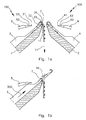
- Fig. 1a shows a front needle bed 1 and a rear needle bed 2 of a flat knitting machine 100 in which latch needles 3, 4 are mounted longitudinally displaceable.
- Over the needle beds 1, 2 are cutting elements 5, 6 for cutting stitches as part of a non-illustrated Mesh cutting device 150 is arranged, which has at least one arranged above the needle beds 1, 2 cutting element bed with a plurality of juxtaposed cutting elements 5, 6.
- the cutting elements 5, 6 each have a tip 51, 61, a breast surface 52, 62 and a cutting surface 53, 63.
- the needle 3 of the front needle bed 1 holds a stitch 7 in its thread space 33, which is bounded by the needle hook 31 and the closed needle tongue 32.
- the needle 3 is located in Fig. 1a ) in its basic position, in which the mesh 7 rests in the direction of the arrow 71 on the tee-off ground 11 of the front needle bed 1 by the action of a knit trigger, not shown.
- the needle 3 was driven by means of a drive device, not shown, in the direction of the arrow 300, wherein the needle tongue 32 was opened by the mesh 7 and the mesh 7 is now on the needle shaft behind the open needle tongue.
- Fig. 1d shows the position of the loop 7 on the needle tongue 32 after completion of the movement in Fig. 1c ).
- the needle 3 has been withdrawn so far that the stitch 7 is in its transfer position, just before its tee.
- the cutting element 5 is now expelled in the direction of the arrow 500 and pushed into the loop 7, ie between introduced her mesh legs.
- the tip 51 of the cutting element thereby slides laterally past the tongue 32 and into the thread space 33 so far that it projects through the loop 7.
- the needle 3 is retracted in the direction of the arrow 301, whereby the mesh 7 is released from it.
- the cutting element 5 is driven so far in the direction of the arrow 500 that the mesh 7 merges with the cutting surface 53 in the direction of the breast surface 52, slides on it and is thereby separated.
- Fig. 1f the needle 3 is back in its basic position.
- the cutting element 5 is also retracted to its home position.
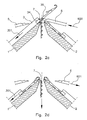
- FIG. 1 While in Fig. 1 the stitch 7 has been severed by a cutting element 5 which is located above the needle 3 with the stitch 7, shows Fig. 2 the separation of the stitch 7 by the cutting element 6, which is located above the opposite needle bed 2.
- Fig. 2a shows the front and back needle bed 1, 2 of the flat knitting machine 100 with the stitch cutter 150 according to FIG Fig. 1 , The needle 3 is in its basic position according to Fig. 1a ).
- the needle 3 was driven in the direction of arrow 300 into its transfer position, wherein the needle tongue 32 was opened by the stitch 7 and the stitch 7 and on the needle shaft behind the open needle tongue 32 is located.
- the mesh 7 was widened by a box spring 34 on the needle 3 to facilitate the immersion of the cutting element 6 into the mesh 7.
- Fig. 2c it is shown how the cutting element 6 expelled in the direction of arrow 600 and is pushed into the mesh 7.
- the tip 61 of the cutting element 6 slides in the space between the box spring 34 and the needle shaft 35 and thereby immersed in the expanded mesh 7 a. Subsequently, a retraction movement of the needle 3, whereby the mesh 7 comes into contact with the cutting surface 63 of the cutting element 6 and is thereby separated.
- Fig. 2d the needle 3 and the cutting element 6 were withdrawn in the directions of arrows 301 and 601 in their basic position.
- the mesh 7 is cut open and has no contact with the needle 3 more.
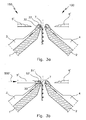
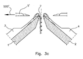
- the cutting elements 5 ', 6' are arranged horizontally for this purpose. The arrangement and design of the needle beds 1, 2 remains unchanged.
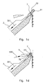
- Fig. 4 shows the transfer of a stitch 7 from a needle 30 to a cutting element 5.
- the slider 35 of the needle 30 and thus the thread space are closed.
- the needle 30 was retracted in the direction of the arrow 331 to its transfer position.
- the mesh 7 is located on the closed slide 35.
- the cutting element 5 was so far advanced in the direction of arrow 500 that its tip 51 pierces into the thread space 36 and thus between the needle 30 and a leg of the mesh 7.
- a variant of the acquisition of the mesh 7 is shown by a latch needle 3 on the cutting element 5.
- the needle 3 has been driven here in the direction of arrow 300 in its mesh transfer position, in which the mesh 7 is located on the open tongue.
- the tip 51 of the cutting element can dip when the cutting element 5 is driven in the direction of arrow 500.
- FIGS. 6a ) and b) show a preferred embodiment of a cutting element 5, 6, wherein the cutting element 5, 6 in Fig. 6a ) in the side view and in Fig. 6b ) is shown in plan view.
- the cutting element 5, 6 has a single cutting surface 53, 63, which operates on one of the two longitudinal sides of the needle.
- the cutting element could also be equipped with two parallel cutting surfaces which operate simultaneously on both sides of the needle.
- FIGS. 7 and 8th For example, two applications of cutting stitches during the current knitting process are described, for example, for cutting contours according to a pattern or for making openings for pockets or the like, as well as for design purposes.
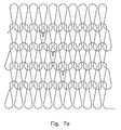
- Fig. 7a shows a double-faced knit piece in which some selected stitches are cut. A stitch of the front and rear needle bed is alternately separated.
- Fig. 7b is clarified, like the knitted fabric Fig. 7a ) can be produced.
- row R1 stitches are formed on the front and back needle beds on the needles AJ and aj.
- row R2 the stitch formed on the needle F of the front needle bed is transferred to the cutting element, not shown here, and cut, before another row of stitches is formed on the front and back needle bed in row R3.
- row R4 the stitch formed on the needle e of the back needle bed is transferred to a cutting element and severed.
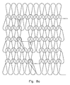
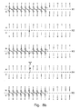
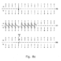
- Fig. 8a shows another double-sided knit. With this knit, only stitches formed on the front needle bed are cut.
- the method of making the knitted fabric from Fig. 8a ) is in Fig. 8b ).
- row R1 stitches are formed on the front and back needle beds with the needles AJ and aj.
- row R2 the stitch formed on the needle f of the back needle bed is transferred to the needle F of the front needle bed, so that there is a double stitch.
- a row of stitches is formed in the row R3 on the front and back needle bed with the needles AJ and with the needles aj, but not with the needle f.
- the stitch formed on the needle F of the front needle bed in row R3 is then transferred to a cutting element and cut.
- row R7 forming a course of stitches with all the needles of the front and back needle bed except for the needle e.
- the stitch of the needle E is transferred to a cutting element in row R8 and cut.
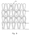
- Fig. 9 illustrates a method of making a plush knit. During manufacture, the picked tuck loops 70 are transferred to the associated cutting elements and cut. All catching loops 70 can be separated or only in certain areas in order to achieve a specific pattern effect.
- FIG. 10 clarified. It is here a secured final mesh after the Kettelrata formed in a knitted piece. The last stitch is transferred to a cutting element and cut, whereby this last stitch is secured in such a way that no running stitch can occur.
Landscapes
- Engineering & Computer Science (AREA)
- Textile Engineering (AREA)
- Knitting Machines (AREA)
Description
Das Aufschneiden von Maschen von Gestricken und Gewirken ist seit langem insbesondere zur Herstellung von Plüschgestricken bekannt. So beschreiben beispielsweise die
Weiter ist es beispielsweise aus der
Die bekannten Lösungen beziehen sich alle auf Rundstrickmaschinen und haben außerdem den Nachteil, dass sie aufwändig in der Herstellung sind, die Möglichkeiten der Maschenbildung einschränken und außerdem die Funktionssicherheit der Maschine beeinträchtigen können.The known solutions all relate to circular knitting machines and also have the disadvantage that they are expensive to manufacture, limit the possibilities of stitch formation and also can impair the reliability of the machine.
Der vorliegenden Erfindung liegt die Aufgabe zugrunde, eine Möglichkeit zum Auftrennen von Maschen oder Fanghenkeln während des Strickvorgangs auf einer Flachstrickmaschine zu schaffen, die auch auf doppelflächige Gestricke anwendbar ist und die Maschenbildung nicht einschränkt.The present invention has for its object to provide a way to separate stitches or tuck loops during the knitting process on a flat knitting machine, which is also applicable to double-surface knitted fabrics and does not limit the stitch formation.
Die Aufgabe wird gelöst durch eine Flachstrickmaschine mit mindestens zwei gegenüberliegend angeordneten Nadelbetten, die jeweils mit einer Vielzahl von Nuten versehen sind, in denen Nadeln längsverschiebbar gelagert sind, die dadurch gekennzeichnet ist, dass mindestens oberhalb eines der Nadelbetten mindestens ein Schneidelementbett angeordnet ist, das mit einer Vielzahl von Nuten versehen ist, in denen Schneidelemente zur Auftrennung von auf den Nadeln gebildeten Maschen oder Fanghenkeln längsverschiebbar angeordnet sind.The object is achieved by a flat knitting machine with at least two oppositely arranged needle beds, which are each provided with a plurality of grooves in which needles are mounted longitudinally displaceable, which is characterized in that at least above one of the needle beds at least one cutting element bed is arranged with a plurality of grooves is provided, in which cutting elements are arranged to longitudinally displaceable for the separation of stitches formed on the needles or tongs.
Durch die in einem separaten Bett gelagerten Schneidelemente ist die Maschenbildung der Strickmaschine in keiner Weise durch die Schneidelemente beeinflusst. Es lassen sich somit ein- und doppelflächige Gestricke sowie Schlauchgestricke in Plüschqualität herstellen. Auch die Musterung der Gestricke ist in keiner Weise beschränkt. Die Lagerung der Schneidelemente in einem oder mehreren separaten Betten ermöglicht auch eine präzise Ansteuerung sowohl der Nadeln als auch der Schneidelemente. Die Funktionssicherheit der Maschine ist daher sehr hoch.Due to the cutting elements mounted in a separate bed, the knitting of the knitting machine is in no way influenced by the cutting elements. It is thus possible to produce single-layer and double-sided knitted fabrics as well as tubular knits in plush quality. The pattern of knitted fabrics is in no way limited. The storage of the cutting elements in one or more separate beds also allows precise control of both the needles and the cutting elements. The reliability of the machine is therefore very high.
Bei einer bevorzugten Ausgestaltung der Maschine entspricht die Nutenteilung des mindestens einen Schneidelementbetts der Nutenteilung der Nadelbetten oder einem Vielfachen der Nutenteilung der Nadelbetten. Somit kann jeder Nadel oder auch jeder zweiten, dritten oder vierten Nadel ein Schneidelement zugeordnet werden. Zum Schneiden der Maschen oder Fanghenkel ist kein seitlicher Versatz der Nadelbetten oder des Schneidelementbetts erforderlich, kann aber bei Teilungen des Schneidelementbetts gröber als die Teilung des Nadelbetts vorgesehen sein.In a preferred embodiment of the machine, the groove pitch of the at least one cutting element bed corresponds to the groove pitch of the needle beds or a multiple of the groove pitch of the needle beds. Thus, each needle or every second, third or fourth needle can be assigned a cutting element. No lateral offset of the needle beds or cutting element bed is required to cut the loops or tuck loops, but may be coarser than the pitch of the needle bed at pitches of the cutting element bed.
Weiter ist es von Vorteil, wenn die Länge des mindestens einen Schneidelementbetts gleich der Länge der Nadelbetten ist. Es können dann Plüschgestricke über die gesamte Länge der Nadelbetten erzeugt werden und nicht nur in bestimmten Bereichen der Nadelbetten.Further, it is advantageous if the length of the at least one cutting element bed is equal to the length of the needle beds. It can then be produced plush knits over the entire length of the needle beds and not only in certain areas of the needle beds.
Es lassen sich auch mehrere Schneidelementbetten nebeneinander oberhalb mindestens eines der Nadelbetten anordnen, wobei jedes Schneidelementbett einem Teilbereich des darunter liegenden Nadelbetts zugeordnet ist. Die einzelnen Schneidelementbetten können dabei die gleiche oder eine unterschiedliche Nutenteilung aufweisen.It is also possible to arrange a plurality of cutting element beds side by side above at least one of the needle beds, wherein each cutting element bed is associated with a portion of the underlying needle bed. The individual cutting element beds can have the same or a different groove pitch.
Zum Auftrennen der Maschen oder Fanghenkel eines Nadelbetts können diese von den Nadeln, auf denen sie sich befinden, auf die Schneidelemente eines über diesem Nadelbett angeordneten Schneidelementbetts übergeben werden. Die Schneidelemente werden hierzu von der Nadelbettenseite her zwischen die Schenkel der Maschen oder Fanghenkel eingeführt.For separating the stitches or tuck loops of a needle bed, these can be transferred from the needles on which they are located to the cutting elements of a cutting element bed arranged above this needle bed. For this purpose, the cutting elements are introduced from the needle bed side between the legs of the stitches or tuck loops.
Das mindestens eine Schneidelementbett kann jedoch auch so angeordnet werden, dass die zu schneidenden Maschen oder Fanghenkel von den Nadeln eines Nadelbetts auf die Schneidelemente eines oberhalb des gegenüberliegenden Nadelbetts angeordneten Schneidelementbetts übergebbar sind. Die Schneidelemente des oberhalb des gegenüberliegenden Nadelbetts angeordneten Schneidelementbetts werden dabei von der Kammspaltseite zwischen die Schenkel der Maschen oder Fanghenkel eingeführt.However, the at least one cutting element bed can also be arranged such that the stitches or tuck loops to be cut can be transferred from the needles of a needle bed to the cutting elements of a cutting element bed arranged above the opposing needle bed. The cutting elements of the above the opposite needle bed arranged cutting element bed are introduced from the comb gap side between the legs of the mesh or tuck loops.
Bei einer bevorzugten Ausgestaltung der Flachstrickmaschine können dabei die zu schneidenden Maschen oder Fanghenkel durch Austrieb der Nadeln auf die Schneidelemente des mindestens einen Schneidelementbetts übergebbar sein. Durch einen entsprechenden Austrieb der Nadel werden die Maschen oder Fanghenkel über den Kammspalt angehoben, sodass durch einen Austrieb der Schneidelemente diese in die Masche oder den Fanghenkel eingeführt werden können. Der Austrieb der Nadeln und Schneidelemente kann beispielsweise über Schlossteile am Maschinenschlitten erfolgen.In a preferred embodiment of the flat knitting machine, the stitches or tuck loops to be cut can be transferred to the cutting elements of the at least one cutting element bed by ejection of the needles. By a corresponding expulsion of the needle, the stitches or tuck loops are lifted over the comb gap, so that they can be introduced into the mesh or the tuck loops by a sprouting of the cutting elements. The expulsion of the needles and cutting elements can be done for example via lock parts on the machine slide.
Die Flachstrickmaschine kann jedoch auch so ausgebildet werden, dass die zu schneidenden Maschen oder Fanghenkel durch eine Bewegung der Schneidelemente des mindestens einen Schneidelementbetts auf die Nadeln zu und ohne Austrieb der Nadeln auftrennbar sind. Die Schneidelementbetten können hierzu in einem relativ großen Winkel zu den v-förmig angeordneten Nadelbetten ausgerichtet und die Schneidelement entsprechen weit ausgetrieben werden.However, the flat knitting machine can also be designed such that the stitches or tuck loops to be cut can be separated by movement of the cutting elements of the at least one cutting element bed onto the needles and without ejection of the needles. For this purpose, the cutting element beds can be aligned at a relatively large angle relative to the needle beds arranged in a v-shape and the cutting elements can be driven out far enough.
Zur Erleichterung des Einführens der Schneidelemente zwischen die Schenkel der zu schneidenden Maschen können die Nadeln vorzugsweise so genannte Kastenfedern zur Spreizung der zu schneidenden Maschen aufweisen.To facilitate the insertion of the cutting elements between the legs of the meshes to be cut, the needles may preferably have so-called box springs for spreading the meshes to be cut.
Die Ausstattung der Nadeln mit Kastenfedern ist jedoch nicht zwingend. Die zu schneidenden Maschen oder Fanghenkel können auf dem Nadelhaken, dem Nadelhals, einer Kastenfeder, der geöffneten oder geschlossenen Nadelzunge oder dem geschlossenen Schieber einer Schiebernadel liegend auf ein Schneidelement übergebbar und/oder durch dieses schneidbar sein. Es sind somit keine besonderen Anforderungen an die verwendeten Nadeln nötig.The equipment of the needles with box springs is not mandatory. The stitches or tuck loops to be cut can be transferred to the cutting hook, the needle neck, a box spring, the open or closed needle tongue or the closed slider of a needle on a cutting element and / or can be cut by this. There are thus no special requirements for the needles used.
Nachfolgend werden bevorzugte Ausführungsbeispiele erfindungsgemäßer Flachstrickmaschinen mit Bezug auf die Zeichnung näher beschrieben.Hereinafter, preferred embodiments of flat knitting machines according to the invention will be described in detail with reference to the drawing.
Es zeigen:
- Fig. 1a) - f)
- einen schematischen Teilquerschnitt durch den Kammspaltbereich der Nadelbetten einer Flachstrickmaschine in verschiedenen Stadien der Übergabe einer Masche auf ein Schneidelement, das oberhalb des die Masche tragenden Nadelbetts gelagert ist;
- Fig. 2a) - d)
- einen der
Figur 1 - Fig. 3a) - c)
- einen Teilquerschnitt durch den Kammspaltbereich einer weiteren Flachstrickmaschine beim Schneiden einer Masche;
- Fig. 4
- einen Teilquerschnitt durch ein Nadelbett beim Schneiden einer Masche auf der geschlossenen Zunge einer Nadel;
- Fig. 5
- einen Teilquerschnitt durch ein Nadelbett beim Schneiden einer Masche auf der offenen Zunge einer Nadel;
- Fig. 6a), b)
- eine Seitenansicht und eine Draufsicht auf ein Schneidelement;
- Fig. 7a), b)
- eine schematische Ansicht eines doppelflächigen Gestricks mit geschnittenen Maschen und eines Verfahrens zu seiner Herstellung;
- Fig. 8a), b)
- eine schematische Ansicht eines zweiten doppelflächigen Gestricks mit geschnittenen Maschen und eines Verfahrens zu seiner Herstellung;
- Fig. 9
- eine schematische Darstellung der Herstellung eines Plüschgestricks;
- Fig. 10
- eine schematische Darstellung der Herstellung einer gesicherten Masche an einem Gestrickabschluss.
- Fig. 1a) - f)
- a schematic partial cross-section through the comb gap region of the needle beds of a flat knitting machine in various stages of the transfer of a stitch on a cutting element which is mounted above the mesh-carrying needle bed;
- Fig. 2a) - d)
- one of the
FIG. 1 corresponding partial cross section in different stages of the transfer of a stitch to a cutting element which is mounted above the opposite needle bed; - Fig. 3a) - c)
- a partial cross section through the comb gap region of another flat knitting machine when cutting a stitch;
- Fig. 4
- a partial cross-section through a needle bed when cutting a stitch on the closed tongue of a needle;
- Fig. 5
- a partial cross-section through a needle bed when cutting a stitch on the open tongue of a needle;
- Fig. 6a), b)
- a side view and a plan view of a cutting element;
- Fig. 7a), b)
- a schematic view of a double-cut knit fabric with cut stitches and a method for its preparation;
- Fig. 8a), b)
- a schematic view of a second double-knitted fabric with cut stitches and a method for its preparation;
- Fig. 9
- a schematic representation of the production of a plush knit;
- Fig. 10
- a schematic representation of the production of a secured mesh on a knitted finish.
Die Nadel 3 des vorderen Nadelbetts 1 hält eine Masche 7 in ihrem Fadenraum 33, der durch den Nadelhaken 31 und die geschlossenen Nadelzunge 32 begrenzt wird.The
Die Nadel 3 befindet sich in
In
In
In
In
Während in
In
In
In
In
In
Die
In den
In
Das Verfahren zur Herstellung des Gestricks aus
In Reihe R6 wird die Masche der Nadel e auf die Nadel E des vorderen Nadelbetts umgehängt, sodass dort eine Doppelmasche entsteht.The method of making the knitted fabric from
In row R6, the stitch of the needle e is transferred to the needle E of the front needle bed, so that a double stitch is formed there.
Anschließend erfolgt in Reihe R7 das Bilden einer Maschenreihe mit allen Nadeln des vorderen und hinteren Nadelbetts mit Ausnahme der Nadel e. Anschließend wird in Reihe R8 die Masche der Nadel E auf ein Schneidelement übergeben und geschnitten.Subsequently, in row R7, forming a course of stitches with all the needles of the front and back needle bed except for the needle e. Subsequently, the stitch of the needle E is transferred to a cutting element in row R8 and cut.
Eine weitere Anwendung des Auftrennens von Maschen ist in
Claims (10)
- Flat knitting machine with at least two opposing needle beds (1, 2) each of which is provided with a multiplicity of grooves in which needles (3, 4) are mounted so as to be displaceable longitudinally, characterised in that at least above one of the needle beds (1, 2) at least one cutting element bed is arranged which is provided with a multiplicity of grooves in which cutting elements (5, 6) for separating stitches (7) or tuck loops formed on the needles (3, 4) are arranged so as to be displaceable longitudinally.
- Flat knitting machine according to claim 1, characterised in that the groove spacing of the at least one cutting element bed corresponds to the groove spacing of the needle beds (1, 2) or to a multiple of the groove spacing of the needle beds (1, 2).
- Flat knitting machine according to one of the previous claims, characterised in that the length of the at least one cutting element bed is the same as the length of the needle beds (1, 2).
- Flat knitting machine according to claim 1 or 2, characterised in that a plurality of cutting element beds are arranged adjacent to each other above at least one of the needle beds (1, 2), whereby each cutting element bed is associated with one area of the needle bed (1, 2) located under it.
- Flat knitting machine according to one of the previous claims, characterised in that the stitches (7) or tuck loops to be cut are deliverable from the needles (3, 4) of a needle bed (1, 2) on to the cutting elements (5, 6) of a cutting element bed arranged over this needle bed (1, 2).
- Flat knitting machine according to one of the previous claims, characterised in that the stitches (7) or tuck loops to be cut are deliverable from the needles (3, 4) of a needle bed (1, 2) on to the cutting elements (5, 6) of a cutting element bed arranged over the opposing needle bed (1, 2).
- Flat knitting machine according to one of the previous claims, characterised in that the stitches (7) or tuck loops to be cut are deliverable on to the cutting elements (5, 6) of the at least one cutting element bed by pushing the needles (3, 4) out.
- Flat knitting machine according to one of the claims 1 to 6, characterised in that the stitches (7) or tuck loops to be cut can be separated by a movement of the cutting elements (5, 6) of the at least one cutting element bed on to the needles (3, 4), towards and without pushing the needles (3, 4) out.
- Flat knitting machine according to one of the previous claims, characterised in that the needles (3, 4) have box-like formed springs to spread out the stitches (7) to be cut.
- Flat knitting machine according to one of the previous claims, characterised in that the stitches (7) or tuck loops to be cut are deliverable on to a cutting element (5, 6) while located on the needle hook (31), the needle shank, a box-like formed spring, the opened or closed needle latch (32) or the closed slider (35) of a compound needle (30) and/or can be cut by said cutting element.
Priority Applications (2)
| Application Number | Priority Date | Filing Date | Title |
|---|---|---|---|
| EP20120169263 EP2666896B1 (en) | 2012-05-24 | 2012-05-24 | Flat knitting machine with cutting elements |
| CN201310197200.6A CN103485067B (en) | 2012-05-24 | 2013-05-24 | Flat knitting machine with cutting elements |
Applications Claiming Priority (1)
| Application Number | Priority Date | Filing Date | Title |
|---|---|---|---|
| EP20120169263 EP2666896B1 (en) | 2012-05-24 | 2012-05-24 | Flat knitting machine with cutting elements |
Publications (2)
| Publication Number | Publication Date |
|---|---|
| EP2666896A1 EP2666896A1 (en) | 2013-11-27 |
| EP2666896B1 true EP2666896B1 (en) | 2014-06-18 |
Family
ID=46168252
Family Applications (1)
| Application Number | Title | Priority Date | Filing Date |
|---|---|---|---|
| EP20120169263 Active EP2666896B1 (en) | 2012-05-24 | 2012-05-24 | Flat knitting machine with cutting elements |
Country Status (2)
| Country | Link |
|---|---|
| EP (1) | EP2666896B1 (en) |
| CN (1) | CN103485067B (en) |
Families Citing this family (2)
| Publication number | Priority date | Publication date | Assignee | Title |
|---|---|---|---|---|
| CN104178897B (en) * | 2014-08-08 | 2016-09-07 | 上海嘉麟杰纺织品股份有限公司 | A kind of have triple knitted layer structures cutting circle function and preparation method thereof |
| CN113293497B (en) * | 2021-06-02 | 2022-09-27 | 东经人造皮草(宁波)有限公司 | Weft knitting ultra-high wool cutting equipment |
Family Cites Families (9)
| Publication number | Priority date | Publication date | Assignee | Title |
|---|---|---|---|---|
| US1120989A (en) | 1913-06-19 | 1914-12-15 | Louis N D Williams | Knitting-machine needle. |
| US1441110A (en) * | 1922-10-20 | 1923-01-02 | Nathan Halperin | Method and apparatus for producing knitted fabric |
| DE1153482B (en) | 1958-02-28 | 1963-08-29 | Fouquet Werk Frauz & Planck | Circular knitting machine for the production of plush fabrics |
| DE2322384C3 (en) | 1973-05-04 | 1985-05-15 | Mayer & Cie Gmbh & Co, 7470 Albstadt | Process for the production of patterned plush goods and multi-system circular knitting machine for carrying out the process |
| JPS5673146A (en) | 1979-11-12 | 1981-06-17 | Wool Dev Int | Knitted having pile and knitting method and machine |
| CN2049645U (en) * | 1989-03-31 | 1989-12-20 | 许景贤 | Pile cutter for knitting machine |
| IT1307796B1 (en) * | 1999-09-14 | 2001-11-19 | Pinzauti Lucia | DEVICE AND PROCEDURE FOR THE CONSTRUCTION OF KNITTED FABRICS WITH THE FORMATION OF HAIR CUT ON A REVERSE KNIT, WHOSE RANGES OF |
| US7614255B2 (en) | 2005-04-06 | 2009-11-10 | Groz-Beckert Kg | Cutting needle |
| CN201003096Y (en) * | 2005-12-15 | 2008-01-09 | 覃唯刚 | Lint knitting frame lint cutting device |
-
2012
- 2012-05-24 EP EP20120169263 patent/EP2666896B1/en active Active
-
2013
- 2013-05-24 CN CN201310197200.6A patent/CN103485067B/en active Active
Also Published As
| Publication number | Publication date |
|---|---|
| EP2666896A1 (en) | 2013-11-27 |
| CN103485067A (en) | 2014-01-01 |
| CN103485067B (en) | 2015-08-19 |
Similar Documents
| Publication | Publication Date | Title |
|---|---|---|
| DE102005062403B3 (en) | Device and method for producing a spacer knitted fabric | |
| DE69809141T2 (en) | Mesh forming method and flat knitting machine therefor | |
| DE3237732A1 (en) | FLAT KNITTING MACHINE WITH NEEDLE SELECTION DEVICE | |
| EP2134892B1 (en) | Spacer knitted fabric and method and knitting machine for the production thereof | |
| EP3556921B1 (en) | Flat knitting machine and method for producing a filigrane knit | |
| WO2009092352A2 (en) | Right/right rib fabric and method and knitting machine for the production thereof | |
| DE4129845A1 (en) | CIRCULAR KNITTING MACHINE FOR THE PRODUCTION OF PLUSH GOODS | |
| DE3024705A1 (en) | METHOD FOR PATTERNING KNITTED PLUSH RODS, AND CIRCULAR KNITTING MACHINE THEREFOR | |
| EP2671989B1 (en) | Knitting cam and method for producing a filigree knit on a flat knitting machine | |
| DE10164550A1 (en) | Needle for knitting or warp knitting machines and knitting machine equipped with them | |
| EP3276062B1 (en) | Warp knitting machine and method for producing a warp knitted item | |
| EP2666896B1 (en) | Flat knitting machine with cutting elements | |
| DE102010017946B4 (en) | Lock system for a flat knitting machine | |
| EP1099786B1 (en) | Method and device for transfering stitches on a knitting machine | |
| EP1477600A2 (en) | Circular knitting machine, particularly for the production of spacer fabrics | |
| DE3135702A1 (en) | METHOD FOR PRODUCING A SINGLE-SIDED, PATTERNED KNITWEAR AND CIRCULAR KNITTING MACHINE FOR CARRYING OUT THE METHOD | |
| EP1262585A1 (en) | Method of retaining loops | |
| DE817340C (en) | Knitwear and machine for their production | |
| DE4301242A1 (en) | Method and device for producing textile spacer fabrics | |
| DE591171C (en) | Knitting machine | |
| DE4301231A1 (en) | Process and device for the production of textile net-like flat structures | |
| DE2820724A1 (en) | ROUND MILLING MACHINE | |
| DE2934668A1 (en) | BOARD FOR KNITTING MACHINE FOR PRODUCING A PLUSH KNIT | |
| EP1464746B1 (en) | Needle for knitting machines and method of splitting a stitch | |
| DE3507004C2 (en) |
Legal Events
| Date | Code | Title | Description |
|---|---|---|---|
| PUAI | Public reference made under article 153(3) epc to a published international application that has entered the european phase |
Free format text: ORIGINAL CODE: 0009012 |
|
| 17P | Request for examination filed |
Effective date: 20130213 |
|
| AK | Designated contracting states |
Kind code of ref document: A1 Designated state(s): AL AT BE BG CH CY CZ DE DK EE ES FI FR GB GR HR HU IE IS IT LI LT LU LV MC MK MT NL NO PL PT RO RS SE SI SK SM TR |
|
| AX | Request for extension of the european patent |
Extension state: BA ME |
|
| RIC1 | Information provided on ipc code assigned before grant |
Ipc: D04B 7/12 20060101AFI20140103BHEP |
|
| GRAP | Despatch of communication of intention to grant a patent |
Free format text: ORIGINAL CODE: EPIDOSNIGR1 |
|
| INTG | Intention to grant announced |
Effective date: 20140220 |
|
| GRAS | Grant fee paid |
Free format text: ORIGINAL CODE: EPIDOSNIGR3 |
|
| GRAA | (expected) grant |
Free format text: ORIGINAL CODE: 0009210 |
|
| AK | Designated contracting states |
Kind code of ref document: B1 Designated state(s): AL AT BE BG CH CY CZ DE DK EE ES FI FR GB GR HR HU IE IS IT LI LT LU LV MC MK MT NL NO PL PT RO RS SE SI SK SM TR |
|
| REG | Reference to a national code |
Ref country code: GB Ref legal event code: FG4D Free format text: NOT ENGLISH |
|
| REG | Reference to a national code |
Ref country code: CH Ref legal event code: EP |
|
| REG | Reference to a national code |
Ref country code: AT Ref legal event code: REF Ref document number: 673439 Country of ref document: AT Kind code of ref document: T Effective date: 20140715 |
|
| REG | Reference to a national code |
Ref country code: IE Ref legal event code: FG4D Free format text: LANGUAGE OF EP DOCUMENT: GERMAN |
|
| REG | Reference to a national code |
Ref country code: DE Ref legal event code: R096 Ref document number: 502012000890 Country of ref document: DE Effective date: 20140731 |
|
| PG25 | Lapsed in a contracting state [announced via postgrant information from national office to epo] |
Ref country code: NO Free format text: LAPSE BECAUSE OF FAILURE TO SUBMIT A TRANSLATION OF THE DESCRIPTION OR TO PAY THE FEE WITHIN THE PRESCRIBED TIME-LIMIT Effective date: 20140918 Ref country code: FI Free format text: LAPSE BECAUSE OF FAILURE TO SUBMIT A TRANSLATION OF THE DESCRIPTION OR TO PAY THE FEE WITHIN THE PRESCRIBED TIME-LIMIT Effective date: 20140618 Ref country code: LT Free format text: LAPSE BECAUSE OF FAILURE TO SUBMIT A TRANSLATION OF THE DESCRIPTION OR TO PAY THE FEE WITHIN THE PRESCRIBED TIME-LIMIT Effective date: 20140618 Ref country code: GR Free format text: LAPSE BECAUSE OF FAILURE TO SUBMIT A TRANSLATION OF THE DESCRIPTION OR TO PAY THE FEE WITHIN THE PRESCRIBED TIME-LIMIT Effective date: 20140919 Ref country code: CY Free format text: LAPSE BECAUSE OF FAILURE TO SUBMIT A TRANSLATION OF THE DESCRIPTION OR TO PAY THE FEE WITHIN THE PRESCRIBED TIME-LIMIT Effective date: 20140618 |
|
| REG | Reference to a national code |
Ref country code: NL Ref legal event code: VDEP Effective date: 20140618 |
|
| REG | Reference to a national code |
Ref country code: LT Ref legal event code: MG4D |
|
| PG25 | Lapsed in a contracting state [announced via postgrant information from national office to epo] |
Ref country code: HR Free format text: LAPSE BECAUSE OF FAILURE TO SUBMIT A TRANSLATION OF THE DESCRIPTION OR TO PAY THE FEE WITHIN THE PRESCRIBED TIME-LIMIT Effective date: 20140618 Ref country code: RS Free format text: LAPSE BECAUSE OF FAILURE TO SUBMIT A TRANSLATION OF THE DESCRIPTION OR TO PAY THE FEE WITHIN THE PRESCRIBED TIME-LIMIT Effective date: 20140618 Ref country code: LV Free format text: LAPSE BECAUSE OF FAILURE TO SUBMIT A TRANSLATION OF THE DESCRIPTION OR TO PAY THE FEE WITHIN THE PRESCRIBED TIME-LIMIT Effective date: 20140618 Ref country code: SE Free format text: LAPSE BECAUSE OF FAILURE TO SUBMIT A TRANSLATION OF THE DESCRIPTION OR TO PAY THE FEE WITHIN THE PRESCRIBED TIME-LIMIT Effective date: 20140618 |
|
| PG25 | Lapsed in a contracting state [announced via postgrant information from national office to epo] |
Ref country code: SK Free format text: LAPSE BECAUSE OF FAILURE TO SUBMIT A TRANSLATION OF THE DESCRIPTION OR TO PAY THE FEE WITHIN THE PRESCRIBED TIME-LIMIT Effective date: 20140618 Ref country code: PT Free format text: LAPSE BECAUSE OF FAILURE TO SUBMIT A TRANSLATION OF THE DESCRIPTION OR TO PAY THE FEE WITHIN THE PRESCRIBED TIME-LIMIT Effective date: 20141020 Ref country code: RO Free format text: LAPSE BECAUSE OF FAILURE TO SUBMIT A TRANSLATION OF THE DESCRIPTION OR TO PAY THE FEE WITHIN THE PRESCRIBED TIME-LIMIT Effective date: 20140618 Ref country code: ES Free format text: LAPSE BECAUSE OF FAILURE TO SUBMIT A TRANSLATION OF THE DESCRIPTION OR TO PAY THE FEE WITHIN THE PRESCRIBED TIME-LIMIT Effective date: 20140618 Ref country code: CZ Free format text: LAPSE BECAUSE OF FAILURE TO SUBMIT A TRANSLATION OF THE DESCRIPTION OR TO PAY THE FEE WITHIN THE PRESCRIBED TIME-LIMIT Effective date: 20140618 Ref country code: EE Free format text: LAPSE BECAUSE OF FAILURE TO SUBMIT A TRANSLATION OF THE DESCRIPTION OR TO PAY THE FEE WITHIN THE PRESCRIBED TIME-LIMIT Effective date: 20140618 |
|
| PG25 | Lapsed in a contracting state [announced via postgrant information from national office to epo] |
Ref country code: PL Free format text: LAPSE BECAUSE OF FAILURE TO SUBMIT A TRANSLATION OF THE DESCRIPTION OR TO PAY THE FEE WITHIN THE PRESCRIBED TIME-LIMIT Effective date: 20140618 Ref country code: IS Free format text: LAPSE BECAUSE OF FAILURE TO SUBMIT A TRANSLATION OF THE DESCRIPTION OR TO PAY THE FEE WITHIN THE PRESCRIBED TIME-LIMIT Effective date: 20141018 Ref country code: NL Free format text: LAPSE BECAUSE OF FAILURE TO SUBMIT A TRANSLATION OF THE DESCRIPTION OR TO PAY THE FEE WITHIN THE PRESCRIBED TIME-LIMIT Effective date: 20140618 |
|
| REG | Reference to a national code |
Ref country code: DE Ref legal event code: R097 Ref document number: 502012000890 Country of ref document: DE |
|
| PLBE | No opposition filed within time limit |
Free format text: ORIGINAL CODE: 0009261 |
|
| STAA | Information on the status of an ep patent application or granted ep patent |
Free format text: STATUS: NO OPPOSITION FILED WITHIN TIME LIMIT |
|
| PG25 | Lapsed in a contracting state [announced via postgrant information from national office to epo] |
Ref country code: DK Free format text: LAPSE BECAUSE OF FAILURE TO SUBMIT A TRANSLATION OF THE DESCRIPTION OR TO PAY THE FEE WITHIN THE PRESCRIBED TIME-LIMIT Effective date: 20140618 |
|
| 26N | No opposition filed |
Effective date: 20150319 |
|
| REG | Reference to a national code |
Ref country code: DE Ref legal event code: R097 Ref document number: 502012000890 Country of ref document: DE Effective date: 20150319 |
|
| PG25 | Lapsed in a contracting state [announced via postgrant information from national office to epo] |
Ref country code: SI Free format text: LAPSE BECAUSE OF FAILURE TO SUBMIT A TRANSLATION OF THE DESCRIPTION OR TO PAY THE FEE WITHIN THE PRESCRIBED TIME-LIMIT Effective date: 20140618 |
|
| REG | Reference to a national code |
Ref country code: CH Ref legal event code: PL |
|
| PG25 | Lapsed in a contracting state [announced via postgrant information from national office to epo] |
Ref country code: LI Free format text: LAPSE BECAUSE OF NON-PAYMENT OF DUE FEES Effective date: 20150531 Ref country code: MC Free format text: LAPSE BECAUSE OF FAILURE TO SUBMIT A TRANSLATION OF THE DESCRIPTION OR TO PAY THE FEE WITHIN THE PRESCRIBED TIME-LIMIT Effective date: 20140618 Ref country code: LU Free format text: LAPSE BECAUSE OF FAILURE TO SUBMIT A TRANSLATION OF THE DESCRIPTION OR TO PAY THE FEE WITHIN THE PRESCRIBED TIME-LIMIT Effective date: 20150524 Ref country code: CH Free format text: LAPSE BECAUSE OF NON-PAYMENT OF DUE FEES Effective date: 20150531 |
|
| REG | Reference to a national code |
Ref country code: IE Ref legal event code: MM4A |
|
| REG | Reference to a national code |
Ref country code: FR Ref legal event code: ST Effective date: 20160129 |
|
| PG25 | Lapsed in a contracting state [announced via postgrant information from national office to epo] |
Ref country code: IE Free format text: LAPSE BECAUSE OF NON-PAYMENT OF DUE FEES Effective date: 20150524 |
|
| PG25 | Lapsed in a contracting state [announced via postgrant information from national office to epo] |
Ref country code: FR Free format text: LAPSE BECAUSE OF NON-PAYMENT OF DUE FEES Effective date: 20150601 |
|
| PG25 | Lapsed in a contracting state [announced via postgrant information from national office to epo] |
Ref country code: MT Free format text: LAPSE BECAUSE OF FAILURE TO SUBMIT A TRANSLATION OF THE DESCRIPTION OR TO PAY THE FEE WITHIN THE PRESCRIBED TIME-LIMIT Effective date: 20140618 |
|
| GBPC | Gb: european patent ceased through non-payment of renewal fee |
Effective date: 20160524 |
|
| PG25 | Lapsed in a contracting state [announced via postgrant information from national office to epo] |
Ref country code: BG Free format text: LAPSE BECAUSE OF FAILURE TO SUBMIT A TRANSLATION OF THE DESCRIPTION OR TO PAY THE FEE WITHIN THE PRESCRIBED TIME-LIMIT Effective date: 20140618 Ref country code: GB Free format text: LAPSE BECAUSE OF NON-PAYMENT OF DUE FEES Effective date: 20160524 Ref country code: SM Free format text: LAPSE BECAUSE OF FAILURE TO SUBMIT A TRANSLATION OF THE DESCRIPTION OR TO PAY THE FEE WITHIN THE PRESCRIBED TIME-LIMIT Effective date: 20140618 Ref country code: HU Free format text: LAPSE BECAUSE OF FAILURE TO SUBMIT A TRANSLATION OF THE DESCRIPTION OR TO PAY THE FEE WITHIN THE PRESCRIBED TIME-LIMIT; INVALID AB INITIO Effective date: 20120524 |
|
| PG25 | Lapsed in a contracting state [announced via postgrant information from national office to epo] |
Ref country code: BE Free format text: LAPSE BECAUSE OF NON-PAYMENT OF DUE FEES Effective date: 20150531 |
|
| PGFP | Annual fee paid to national office [announced via postgrant information from national office to epo] |
Ref country code: TR Payment date: 20170522 Year of fee payment: 6 |
|
| PG25 | Lapsed in a contracting state [announced via postgrant information from national office to epo] |
Ref country code: MK Free format text: LAPSE BECAUSE OF FAILURE TO SUBMIT A TRANSLATION OF THE DESCRIPTION OR TO PAY THE FEE WITHIN THE PRESCRIBED TIME-LIMIT Effective date: 20140618 |
|
| REG | Reference to a national code |
Ref country code: AT Ref legal event code: MM01 Ref document number: 673439 Country of ref document: AT Kind code of ref document: T Effective date: 20170524 |
|
| PG25 | Lapsed in a contracting state [announced via postgrant information from national office to epo] |
Ref country code: AT Free format text: LAPSE BECAUSE OF NON-PAYMENT OF DUE FEES Effective date: 20170524 |
|
| PG25 | Lapsed in a contracting state [announced via postgrant information from national office to epo] |
Ref country code: AL Free format text: LAPSE BECAUSE OF FAILURE TO SUBMIT A TRANSLATION OF THE DESCRIPTION OR TO PAY THE FEE WITHIN THE PRESCRIBED TIME-LIMIT Effective date: 20140618 |
|
| REG | Reference to a national code |
Ref country code: DE Ref legal event code: R082 Ref document number: 502012000890 Country of ref document: DE Representative=s name: KOHLER SCHMID MOEBUS PATENTANWAELTE PARTNERSCH, DE Ref country code: DE Ref legal event code: R081 Ref document number: 502012000890 Country of ref document: DE Owner name: KARL MAYER STOLL R&D GMBH, DE Free format text: FORMER OWNER: H. STOLL GMBH & CO. KG, 72760 REUTLINGEN, DE |
|
| PGFP | Annual fee paid to national office [announced via postgrant information from national office to epo] |
Ref country code: DE Payment date: 20230525 Year of fee payment: 12 |
|
| P01 | Opt-out of the competence of the unified patent court (upc) registered |
Effective date: 20230630 |
|
| PG25 | Lapsed in a contracting state [announced via postgrant information from national office to epo] |
Ref country code: TR Free format text: LAPSE BECAUSE OF NON-PAYMENT OF DUE FEES Effective date: 20180524 |
|
| PGFP | Annual fee paid to national office [announced via postgrant information from national office to epo] |
Ref country code: IT Payment date: 20240524 Year of fee payment: 13 |