EP1464746B1 - Aiguille pour métiers à tricoter et procédé pour la partition d'une maille - Google Patents
Aiguille pour métiers à tricoter et procédé pour la partition d'une maille Download PDFInfo
- Publication number
- EP1464746B1 EP1464746B1 EP20030007640 EP03007640A EP1464746B1 EP 1464746 B1 EP1464746 B1 EP 1464746B1 EP 20030007640 EP20030007640 EP 20030007640 EP 03007640 A EP03007640 A EP 03007640A EP 1464746 B1 EP1464746 B1 EP 1464746B1
- Authority
- EP
- European Patent Office
- Prior art keywords
- needle
- stitch
- hook
- latch
- needles
- Prior art date
- Legal status (The legal status is an assumption and is not a legal conclusion. Google has not performed a legal analysis and makes no representation as to the accuracy of the status listed.)
- Expired - Fee Related
Links
Images
Classifications
-
- D—TEXTILES; PAPER
- D04—BRAIDING; LACE-MAKING; KNITTING; TRIMMINGS; NON-WOVEN FABRICS
- D04B—KNITTING
- D04B35/00—Details of, or auxiliary devices incorporated in, knitting machines, not otherwise provided for
- D04B35/02—Knitting tools or instruments not provided for in group D04B15/00 or D04B27/00
- D04B35/04—Latch needles
-
- D—TEXTILES; PAPER
- D04—BRAIDING; LACE-MAKING; KNITTING; TRIMMINGS; NON-WOVEN FABRICS
- D04B—KNITTING
- D04B1/00—Weft knitting processes for the production of fabrics or articles not dependent on the use of particular machines; Fabrics or articles defined by such processes
Definitions
- the invention relates to a method for meshing with a knitting machine and the use of a knitting needle in this method.
- the splitting of meshes is a relatively frequently desired process in the manufacture of technically complex knits.
- a mesh part is advantageous in the transition from a single-surface knitted fabric to a double-sided knitted fabric.
- a piece of mesh also allows a whole range of knitting bindings that would otherwise not be produced.
- the object of the present invention is to propose a method by which a genuine stitch splitting operation with latch needles is possible, and to provide a method of how a stitch splitting can be performed.
- the beginning of the method according to the invention corresponds to the method for transferring a stitch from one needle to the opposite needle.
- Enabling passage of the needle hook of the opposing needle between the loop leg and the needle shaft of the needle originally holding the loop can be achieved in a manner known per se by a spreading spring on the needle pushing the mesh leg outwards.
- the stitching section allows, in contrast to the tongue needles usually used now to hold the stitch to be divided in this area and then to slide by a propulsion of the needle, the stitch in the needle hook, while the opposite needle already holds the stitch in her needle hook.
- the stitch with its head and one leg on the original needle holding the stitch and the other leg in the hook of the opposite needle is carried out both on a flat knitting machine and on a circular knitting machine.
- the object also relates to the use of a needle for knitting machines with a pivotally mounted and in an end position the needle hook closing tongue in a method according to the invention, in which between the tongue tip in the needle hook closing end position and the beginning of the rounded portion of the needle hook head a stitch support section is arranged ,
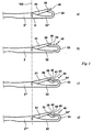
- Fig. 1a the front portion of a latch needle 3 '' according to the prior art is shown.
- the needle 3 "has a needle neck 32", a needle head 33 and a needle tip 35 at the end of the needle hook.
- a tongue 31 is provided which is rotatably mounted about a pivot point D which lies on a line 100.
- the tongue 31 is shown in its end position closing the needle hook.
- the end 38 of the tongue covers the needle tip 35 and terminates immediately at the beginning of the rounded portion of the hook head 33. This means that a stitch that slides over the tongue 31 and the tongue tip 38 jumps directly onto the rounded portion of the hook head 33 and from
- 1b shows a needle neck 32, which is opposite the needle neck 32 "of the needle 3 '' extended and has a correspondingly deeper needle hook. Also, the free leg 34 of the needle hook is longer here than in the needle 3 '', so that between the tip 38 of the tongue 31 and the hook head 33 results in a Mascheauflagesetation 40 on which a mesh can be held. This means that a by a retraction movement of the needle 3 via the tongue 31 and the tongue tip 38 sliding mesh first jumps on the mesh support section 40 and can be held there when the needle 3 is not retracted further. Only by further retraction of the needle 3, the stitch then slides over the hook head 33 in the mesh as in the needle 3 ''.
- FIGS. 1c and 1d show alternative embodiments of needles 3 "', 3" "according to the invention, which are each likewise provided with mesh support sections 40', 40".
- the free leg 34 'of the hook of the needle 3' '' has an approximately V-shaped recess 41, the tip of which is rounded off, and the rounding at the tip merges into a straight line 43 leading to the hook head 33, and on the opposite side into a straight line 42 which extends to the needle tip 35.
- the recess 41 is in the needle 3 '' 'an even better grip of the stitch on the mesh support section 40' as in the Needle 3 given.
- Fig. 1d shows a needle 3 "" which is very similar to the needle 3 "'of Fig. 1c.
- the stitch support section 40 " is also provided with a rounded recess 44, but now merges with arcuate portions 45, 46 to the needle tip 35 and the hook head 33.
- the needles 3 '' 'and 3" ", the Recesses 41, 44 formed by a corresponding undulating configuration of the free legs 34 'and 34' 'of the needle hook.
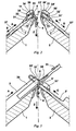
- FIGS. 2 to 7 now illustrate how, with a flat knitting machine having two opposing needle beds 1, 2, which are equipped with needles 3, 3 'according to FIG. 1b, the division of a stitch 5 can be carried out.
- Fig. 2 shows the stitch 5 originally holding the needle 3 on the needle bed 1 and arranged on the opposite needle bed 2 needle 3 'in its basic position.
- the needle 3 is in the direction of arrow A away and in the direction of arrow B inwardly movable.
- the needle 3 ' can drive out in the direction of arrow C. and retract in the direction of arrow B again.
- the stitch 5 of the last knitted stitch row of the knitted fabric 4 is held in the hook space 36 of the needles 3 of the needle bed 1.
- An unillustrated trigger moves the fabric 4 in the direction of arrow Z down. This pull-off force results in the stitch 5, which is supported on a tee wire 12, a tension which is necessary for the stitch formation and for a transfer operation to the needle bed 2 and for the stitch sharing method shown here.
- a spreading spring 38 is also arranged, which spreads the leg 5 'of the mesh 5 laterally from the needle shaft. This makes it possible, with a spurt of the needle 3 'in the direction of arrow C, the hook of this needle 3' between the shaft of the needle 3 and the mesh leg 5 'pass, until the syringe 35' of the needle hook is above the stitch head 5.
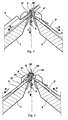
- the needle 3 ' is subsequently withdrawn in the direction of the arrow D until the loop 5 comes to rest within the hook space 36' of the loop 3 '.
- the needle 3 is retracted in the direction of arrow B, to such an extent that the loop 5 closes the tongue 31 of the needle 3 and comes to lie on the extended leg 34 of the needle hook of the needle 3, as shown in FIG.
- the stitch 5 is now so in the hook space 36 of the needle 3 'and at the same time on the mesh support section 40 and the leg 34 of the hook of the needle 3.
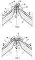
- the needle 3 is now expelled again in the direction of arrow A, as shown in FIG shows.
- Austriebsterrorism resting on the leg 34 stitch 5 opens the tongue 31 of the needle.
Landscapes
- Engineering & Computer Science (AREA)
- Textile Engineering (AREA)
- Knitting Machines (AREA)
Claims (7)
- Procédé pour diviser une maille (5) sur une machine à tricoter équipée d'aiguilles (3, 3') opposées et munies d'un clapet (31, 31') qui peut pivoter et qui ferme les crochets d'aiguille dans une position finale, une section d'appui de maille (40, 40', 40'') se trouvant entre la pointe de clapet (38) quand le clapet (31, 31') est en position finale qui ferme le crochet d'aiguille et le début de la zone arrondie de la tête (33, 33') du crochet d'aiguille, caractérisé par les étapes suivantes :- expulser l'aiguille (3) munie de la maille (5) à diviser jusqu'à ce que sa tête soit en contact avec un épaulement (37) formé sur le talon d'aiguille,- expulser l'aiguille (3') opposée et passer le crochet d'aiguille entre le talon de l'aiguille (3) qui porte la maille (5) et le montant (5') de la maille (5) à diviser,- tirer en arrière les deux aiguilles (3, 3') jusqu'à ce que la tête de maille se trouve sur le talon de l'aiguille (3) qui portait à l'origine la maille et en même temps dans le crochet d'aiguille (36') de l'aiguille (3') opposée,- tirer plus en arrière l'aiguille (3) qui portait à l'origine la maille (5) jusqu'à ce que la maille (5) ferme le talon (31) de cette aiguille (3) et repose sur la section d'appui de maille (40),- avancer l'aiguille (3) qui portait à l'origine la maille (5), la maille (5) ouvrant alors le clapet (31) et glissant dans le crochet d'aiguille (36) de cette aiguille,- tirer en arrière les deux aiguilles (3, 3') en position de base, la maille (5) se trouvant maintenant en même temps dans les deux crochets d'aiguille (36, 36').
- Utilisation d'une aiguille (3, 3', 3''', 3"") dans un procédé selon la revendication 1 pour des machines à tricoter équipées d'un clapet (31, 31') qui est monté pivotant et qui ferme le crochet d'aiguille dans une position finale, dans laquelle une section d'appui de maille (40, 40', 40") se trouve entre la pointe de clapet (38) quand le clapet (31, 31') est en position finale qui ferme le crochet d'aiguille et le début de la zone arrondie de la tête (33, 33') du crochet d'aiguille.
- Utilisation d'une aiguille suivant la revendication 2, dans laquelle la section d'appui de maille (40) de l'aiguille est formée par un segment rectiligne de la branche (34) libre du crochet d'aiguille.
- Utilisation d'une aiguille suivant la revendication 2, dans laquelle la section d'appui de maille (40, 40') présente un renfoncement (41, 44).
- Utilisation d'une aiguille suivant la revendication 4, caractérisée en ce que le renfoncement (41) forme à peu près un V.
- Utilisation d'une aiguille suivant la revendication 4 ou 5, caractérisée en ce que le renfoncement (41, 44) est formé par une structure ondulée de la branche (34, 34'') libre du crochet d'aiguille. formé par une structure ondulée de la branche (34 , 34") libre du crochet d' aiguille .
- Utilisation d'une aiguille suivant l'une des revendications 2 à 6, caractérisée en ce que le clapet (31, 31') de l'aiguille (3, 3', 3''', 3'''') peut venir en ses positions finales à l'encontre de la résistance d'un ressort.
Priority Applications (4)
| Application Number | Priority Date | Filing Date | Title |
|---|---|---|---|
| DE50303358T DE50303358D1 (de) | 2003-04-03 | 2003-04-03 | Nadel für Strickmaschinen und Verfahren zum Teilen einer Masche |
| ES03007640T ES2260535T3 (es) | 2003-04-03 | 2003-04-03 | Aguja para tricotosas y metodo para la participacion de una malla. |
| EP20030007640 EP1464746B1 (fr) | 2003-04-03 | 2003-04-03 | Aiguille pour métiers à tricoter et procédé pour la partition d'une maille |
| CNB2004100323470A CN100478512C (zh) | 2003-04-03 | 2004-04-02 | 用针在针织机上分线圈的方法以及所述针的用途 |
Applications Claiming Priority (1)
| Application Number | Priority Date | Filing Date | Title |
|---|---|---|---|
| EP20030007640 EP1464746B1 (fr) | 2003-04-03 | 2003-04-03 | Aiguille pour métiers à tricoter et procédé pour la partition d'une maille |
Publications (2)
| Publication Number | Publication Date |
|---|---|
| EP1464746A1 EP1464746A1 (fr) | 2004-10-06 |
| EP1464746B1 true EP1464746B1 (fr) | 2006-05-17 |
Family
ID=32842748
Family Applications (1)
| Application Number | Title | Priority Date | Filing Date |
|---|---|---|---|
| EP20030007640 Expired - Fee Related EP1464746B1 (fr) | 2003-04-03 | 2003-04-03 | Aiguille pour métiers à tricoter et procédé pour la partition d'une maille |
Country Status (4)
| Country | Link |
|---|---|
| EP (1) | EP1464746B1 (fr) |
| CN (1) | CN100478512C (fr) |
| DE (1) | DE50303358D1 (fr) |
| ES (1) | ES2260535T3 (fr) |
Families Citing this family (3)
| Publication number | Priority date | Publication date | Assignee | Title |
|---|---|---|---|---|
| DE502007005757D1 (de) * | 2007-06-15 | 2011-01-05 | Stoll H Gmbh & Co Kg | Verfahren zum Einbinden eines Strickfadenfangs und/oder-endes |
| JP2012077418A (ja) * | 2010-10-04 | 2012-04-19 | Shima Seiki Mfg Ltd | 編目の割増やし方法 |
| CN109750414B (zh) * | 2019-02-28 | 2024-02-06 | 宁波慈星股份有限公司 | 横机的复合针 |
Family Cites Families (3)
| Publication number | Priority date | Publication date | Assignee | Title |
|---|---|---|---|---|
| US2124305A (en) * | 1937-03-08 | 1938-07-19 | Lombardi Knitting Machine Co I | Knitting needle and method of use |
| DE3702019C1 (de) * | 1987-01-24 | 1987-09-24 | Groz & Soehne Theodor | Zungennadel fuer maschenbildende Textilmaschinen |
| US5305619A (en) * | 1990-03-26 | 1994-04-26 | Shima Seiki Mfg. Ltd. | Stitch increasing method and cams for flat knitting machine having stitch increasing function |
-
2003
- 2003-04-03 EP EP20030007640 patent/EP1464746B1/fr not_active Expired - Fee Related
- 2003-04-03 ES ES03007640T patent/ES2260535T3/es not_active Expired - Lifetime
- 2003-04-03 DE DE50303358T patent/DE50303358D1/de not_active Expired - Lifetime
-
2004
- 2004-04-02 CN CNB2004100323470A patent/CN100478512C/zh not_active Expired - Fee Related
Also Published As
| Publication number | Publication date |
|---|---|
| DE50303358D1 (de) | 2006-06-22 |
| CN100478512C (zh) | 2009-04-15 |
| CN1536117A (zh) | 2004-10-13 |
| ES2260535T3 (es) | 2006-11-01 |
| EP1464746A1 (fr) | 2004-10-06 |
Similar Documents
| Publication | Publication Date | Title |
|---|---|---|
| DE1964970A1 (de) | Nadel fuer Strick- und Wirkmaschinen | |
| DE3237732A1 (de) | Flachstrickmaschine mit nadelauswahleinrichtung | |
| EP3507406A1 (fr) | Aiguille servant à la formation de mailles sur un métier à tricoter ou un métier à mailles jetées, métier à tricoter ou métier à mailles jetées comprenant plusieurs telles aiguilles et procédé permettant de fabriquer une telle aiguille | |
| DE2617303C2 (de) | Plüschrundstrickmaschine | |
| DE2455764A1 (de) | Schiebeelemente in einer einzylinderrundstrickmaschine | |
| DE10164550A1 (de) | Nadel für Strick- oder Wirkmaschinen und damit ausgerüstete Strickmaschine | |
| DE3151225C2 (de) | Nadel für Flachstrickmaschinen | |
| DE2909963A1 (de) | Verfahren zur maschinellen maschenbildung sowie strick- oder wirkmaschine zur ausfuehrung des verfahrens | |
| EP1464746B1 (fr) | Aiguille pour métiers à tricoter et procédé pour la partition d'une maille | |
| DE102010017946B4 (de) | Schlosssystem für eine Flachstrickmaschine | |
| EP1522618B1 (fr) | Platine pour un métier à tricoter rectiligne | |
| EP1757721B1 (fr) | Aiguille de transfert et méthode pour le transfert de maille | |
| DE2820724C2 (de) | Mehrsystemige Rundstrickmaschine | |
| WO2018114025A1 (fr) | Machine à crocheter | |
| DE1209692B (de) | Zweisystemige Strumpfrundstrickmaschine | |
| EP1467010A1 (fr) | Métier à tricoter rectiligne avec au moins deux fontures | |
| EP2666896B1 (fr) | Machine à tricoter rectiligne dotée d'éléments de découpe | |
| DE2647185A1 (de) | Verfahren und vorrichtung zur maschenbildung | |
| DD235283A1 (de) | Vielsystemige rundstrickmaschine, insbesondere r/l-grossrundstrickmaschine | |
| DE911166C (de) | Verfahren und flache Kulierwirkmaschine zum Laenger-als-gewoehnlich-Kulieren und -Verteilen von Schleifen | |
| DE1560935C (de) | Rundstrickmaschine | |
| DE2535197A1 (de) | Plueschware, sowie verfahren und rundstrickmaschine zu deren herstellung | |
| DE1585272C3 (fr) | ||
| EP3670725A1 (fr) | Aiguille de formation de mailles sur un métier à tricoter ou un métier à mailles jetées et métier à tricoter ou métier à mailles jetées doté d'une pluralité de telles aiguilles | |
| DE588901C (de) | Einrichtung zum Bemessen der Maschen auf Strick-, insbesondere Rundstrickmaschinen |
Legal Events
| Date | Code | Title | Description |
|---|---|---|---|
| PUAI | Public reference made under article 153(3) epc to a published international application that has entered the european phase |
Free format text: ORIGINAL CODE: 0009012 |
|
| AK | Designated contracting states |
Kind code of ref document: A1 Designated state(s): AT BE BG CH CY CZ DE DK EE ES FI FR GB GR HU IE IT LI LU MC NL PT RO SE SI SK TR |
|
| AX | Request for extension of the european patent |
Extension state: AL LT LV MK |
|
| 17P | Request for examination filed |
Effective date: 20050223 |
|
| AKX | Designation fees paid |
Designated state(s): DE ES IT |
|
| GRAP | Despatch of communication of intention to grant a patent |
Free format text: ORIGINAL CODE: EPIDOSNIGR1 |
|
| GRAS | Grant fee paid |
Free format text: ORIGINAL CODE: EPIDOSNIGR3 |
|
| GRAA | (expected) grant |
Free format text: ORIGINAL CODE: 0009210 |
|
| AK | Designated contracting states |
Kind code of ref document: B1 Designated state(s): DE ES IT |
|
| PG25 | Lapsed in a contracting state [announced via postgrant information from national office to epo] |
Ref country code: IT Free format text: LAPSE BECAUSE OF FAILURE TO SUBMIT A TRANSLATION OF THE DESCRIPTION OR TO PAY THE FEE WITHIN THE PRESCRIBED TIME-LIMIT;WARNING: LAPSES OF ITALIAN PATENTS WITH EFFECTIVE DATE BEFORE 2007 MAY HAVE OCCURRED AT ANY TIME BEFORE 2007. THE CORRECT EFFECTIVE DATE MAY BE DIFFERENT FROM THE ONE RECORDED. Effective date: 20060517 |
|
| REF | Corresponds to: |
Ref document number: 50303358 Country of ref document: DE Date of ref document: 20060622 Kind code of ref document: P |
|
| REG | Reference to a national code |
Ref country code: ES Ref legal event code: FG2A Ref document number: 2260535 Country of ref document: ES Kind code of ref document: T3 |
|
| PLBE | No opposition filed within time limit |
Free format text: ORIGINAL CODE: 0009261 |
|
| STAA | Information on the status of an ep patent application or granted ep patent |
Free format text: STATUS: NO OPPOSITION FILED WITHIN TIME LIMIT |
|
| 26N | No opposition filed |
Effective date: 20070220 |
|
| PGFP | Annual fee paid to national office [announced via postgrant information from national office to epo] |
Ref country code: ES Payment date: 20080418 Year of fee payment: 6 |
|
| PGFP | Annual fee paid to national office [announced via postgrant information from national office to epo] |
Ref country code: IT Payment date: 20080408 Year of fee payment: 6 |
|
| REG | Reference to a national code |
Ref country code: ES Ref legal event code: FD2A Effective date: 20090404 |
|
| PG25 | Lapsed in a contracting state [announced via postgrant information from national office to epo] |
Ref country code: ES Free format text: LAPSE BECAUSE OF NON-PAYMENT OF DUE FEES Effective date: 20090404 |
|
| PG25 | Lapsed in a contracting state [announced via postgrant information from national office to epo] |
Ref country code: IT Free format text: LAPSE BECAUSE OF NON-PAYMENT OF DUE FEES Effective date: 20090403 |
|
| PGFP | Annual fee paid to national office [announced via postgrant information from national office to epo] |
Ref country code: DE Payment date: 20170404 Year of fee payment: 15 |
|
| REG | Reference to a national code |
Ref country code: DE Ref legal event code: R119 Ref document number: 50303358 Country of ref document: DE |
|
| PG25 | Lapsed in a contracting state [announced via postgrant information from national office to epo] |
Ref country code: DE Free format text: LAPSE BECAUSE OF NON-PAYMENT OF DUE FEES Effective date: 20181101 |