EP1074087B1 - Regelverfahren und vorrichtung für die brennkraftmaschine eines elektrischen hybridfahrzeuges - Google Patents
Regelverfahren und vorrichtung für die brennkraftmaschine eines elektrischen hybridfahrzeuges Download PDFInfo
- Publication number
- EP1074087B1 EP1074087B1 EP99925573A EP99925573A EP1074087B1 EP 1074087 B1 EP1074087 B1 EP 1074087B1 EP 99925573 A EP99925573 A EP 99925573A EP 99925573 A EP99925573 A EP 99925573A EP 1074087 B1 EP1074087 B1 EP 1074087B1
- Authority
- EP
- European Patent Office
- Prior art keywords
- engine
- motor
- generator
- torque
- output
- Prior art date
- Legal status (The legal status is an assumption and is not a legal conclusion. Google has not performed a legal analysis and makes no representation as to the accuracy of the status listed.)
- Expired - Lifetime
Links
- 238000000034 method Methods 0.000 title claims abstract description 19
- 238000002485 combustion reaction Methods 0.000 title claims abstract description 17
- 230000005540 biological transmission Effects 0.000 claims description 46
- 230000001133 acceleration Effects 0.000 claims description 21
- 230000008859 change Effects 0.000 claims description 15
- 230000004044 response Effects 0.000 claims description 12
- 238000012360 testing method Methods 0.000 claims description 5
- 230000008878 coupling Effects 0.000 claims 1
- 238000010168 coupling process Methods 0.000 claims 1
- 238000005859 coupling reaction Methods 0.000 claims 1
- 239000007858 starting material Substances 0.000 description 12
- 230000007423 decrease Effects 0.000 description 8
- 238000010586 diagram Methods 0.000 description 8
- 239000008186 active pharmaceutical agent Substances 0.000 description 6
- 239000000446 fuel Substances 0.000 description 6
- 230000008929 regeneration Effects 0.000 description 6
- 238000011069 regeneration method Methods 0.000 description 6
- 231100000241 scar Toxicity 0.000 description 6
- 230000000994 depressogenic effect Effects 0.000 description 5
- 238000001914 filtration Methods 0.000 description 5
- 230000007704 transition Effects 0.000 description 4
- 230000008901 benefit Effects 0.000 description 3
- 230000001419 dependent effect Effects 0.000 description 3
- 238000004146 energy storage Methods 0.000 description 3
- 239000003990 capacitor Substances 0.000 description 2
- 238000006243 chemical reaction Methods 0.000 description 2
- 230000001351 cycling effect Effects 0.000 description 2
- 230000003247 decreasing effect Effects 0.000 description 2
- 230000007812 deficiency Effects 0.000 description 2
- 230000009977 dual effect Effects 0.000 description 2
- 230000000694 effects Effects 0.000 description 2
- 230000004048 modification Effects 0.000 description 2
- 238000012986 modification Methods 0.000 description 2
- 230000008569 process Effects 0.000 description 2
- 230000001052 transient effect Effects 0.000 description 2
- 230000009471 action Effects 0.000 description 1
- 239000000654 additive Substances 0.000 description 1
- 230000000996 additive effect Effects 0.000 description 1
- 238000013459 approach Methods 0.000 description 1
- 238000011217 control strategy Methods 0.000 description 1
- 125000004122 cyclic group Chemical group 0.000 description 1
- 230000001627 detrimental effect Effects 0.000 description 1
- 238000004870 electrical engineering Methods 0.000 description 1
- 230000005611 electricity Effects 0.000 description 1
- 238000012545 processing Methods 0.000 description 1
- 230000001172 regenerating effect Effects 0.000 description 1
- 238000005096 rolling process Methods 0.000 description 1
- AFEHBIGDWIGTEH-AQRCPPRCSA-N semax Chemical compound C([C@H](NC(=O)[C@H](CCC(O)=O)NC(=O)[C@@H](N)CCSC)C(=O)N[C@@H](CC=1C=CC=CC=1)C(=O)N1[C@@H](CCC1)C(=O)NCC(=O)N1[C@@H](CCC1)C(O)=O)C1=CNC=N1 AFEHBIGDWIGTEH-AQRCPPRCSA-N 0.000 description 1
- 239000013589 supplement Substances 0.000 description 1
- 230000001502 supplementing effect Effects 0.000 description 1
- 238000012956 testing procedure Methods 0.000 description 1
Images


Classifications
-
- B—PERFORMING OPERATIONS; TRANSPORTING
- B60—VEHICLES IN GENERAL
- B60K—ARRANGEMENT OR MOUNTING OF PROPULSION UNITS OR OF TRANSMISSIONS IN VEHICLES; ARRANGEMENT OR MOUNTING OF PLURAL DIVERSE PRIME-MOVERS IN VEHICLES; AUXILIARY DRIVES FOR VEHICLES; INSTRUMENTATION OR DASHBOARDS FOR VEHICLES; ARRANGEMENTS IN CONNECTION WITH COOLING, AIR INTAKE, GAS EXHAUST OR FUEL SUPPLY OF PROPULSION UNITS IN VEHICLES
- B60K6/00—Arrangement or mounting of plural diverse prime-movers for mutual or common propulsion, e.g. hybrid propulsion systems comprising electric motors and internal combustion engines ; Control systems therefor, i.e. systems controlling two or more prime movers, or controlling one of these prime movers and any of the transmission, drive or drive units Informative references: mechanical gearings with secondary electric drive F16H3/72; arrangements for handling mechanical energy structurally associated with the dynamo-electric machine H02K7/00; machines comprising structurally interrelated motor and generator parts H02K51/00; dynamo-electric machines not otherwise provided for in H02K see H02K99/00
- B60K6/20—Arrangement or mounting of plural diverse prime-movers for mutual or common propulsion, e.g. hybrid propulsion systems comprising electric motors and internal combustion engines ; Control systems therefor, i.e. systems controlling two or more prime movers, or controlling one of these prime movers and any of the transmission, drive or drive units Informative references: mechanical gearings with secondary electric drive F16H3/72; arrangements for handling mechanical energy structurally associated with the dynamo-electric machine H02K7/00; machines comprising structurally interrelated motor and generator parts H02K51/00; dynamo-electric machines not otherwise provided for in H02K see H02K99/00 the prime-movers consisting of electric motors and internal combustion engines, e.g. HEVs
- B60K6/42—Arrangement or mounting of plural diverse prime-movers for mutual or common propulsion, e.g. hybrid propulsion systems comprising electric motors and internal combustion engines ; Control systems therefor, i.e. systems controlling two or more prime movers, or controlling one of these prime movers and any of the transmission, drive or drive units Informative references: mechanical gearings with secondary electric drive F16H3/72; arrangements for handling mechanical energy structurally associated with the dynamo-electric machine H02K7/00; machines comprising structurally interrelated motor and generator parts H02K51/00; dynamo-electric machines not otherwise provided for in H02K see H02K99/00 the prime-movers consisting of electric motors and internal combustion engines, e.g. HEVs characterised by the architecture of the hybrid electric vehicle
- B60K6/46—Series type
-
- B—PERFORMING OPERATIONS; TRANSPORTING
- B60—VEHICLES IN GENERAL
- B60W—CONJOINT CONTROL OF VEHICLE SUB-UNITS OF DIFFERENT TYPE OR DIFFERENT FUNCTION; CONTROL SYSTEMS SPECIALLY ADAPTED FOR HYBRID VEHICLES; ROAD VEHICLE DRIVE CONTROL SYSTEMS FOR PURPOSES NOT RELATED TO THE CONTROL OF A PARTICULAR SUB-UNIT
- B60W20/00—Control systems specially adapted for hybrid vehicles
- B60W20/30—Control strategies involving selection of transmission gear ratio
-
- B—PERFORMING OPERATIONS; TRANSPORTING
- B60—VEHICLES IN GENERAL
- B60K—ARRANGEMENT OR MOUNTING OF PROPULSION UNITS OR OF TRANSMISSIONS IN VEHICLES; ARRANGEMENT OR MOUNTING OF PLURAL DIVERSE PRIME-MOVERS IN VEHICLES; AUXILIARY DRIVES FOR VEHICLES; INSTRUMENTATION OR DASHBOARDS FOR VEHICLES; ARRANGEMENTS IN CONNECTION WITH COOLING, AIR INTAKE, GAS EXHAUST OR FUEL SUPPLY OF PROPULSION UNITS IN VEHICLES
- B60K6/00—Arrangement or mounting of plural diverse prime-movers for mutual or common propulsion, e.g. hybrid propulsion systems comprising electric motors and internal combustion engines ; Control systems therefor, i.e. systems controlling two or more prime movers, or controlling one of these prime movers and any of the transmission, drive or drive units Informative references: mechanical gearings with secondary electric drive F16H3/72; arrangements for handling mechanical energy structurally associated with the dynamo-electric machine H02K7/00; machines comprising structurally interrelated motor and generator parts H02K51/00; dynamo-electric machines not otherwise provided for in H02K see H02K99/00
- B60K6/20—Arrangement or mounting of plural diverse prime-movers for mutual or common propulsion, e.g. hybrid propulsion systems comprising electric motors and internal combustion engines ; Control systems therefor, i.e. systems controlling two or more prime movers, or controlling one of these prime movers and any of the transmission, drive or drive units Informative references: mechanical gearings with secondary electric drive F16H3/72; arrangements for handling mechanical energy structurally associated with the dynamo-electric machine H02K7/00; machines comprising structurally interrelated motor and generator parts H02K51/00; dynamo-electric machines not otherwise provided for in H02K see H02K99/00 the prime-movers consisting of electric motors and internal combustion engines, e.g. HEVs
- B60K6/42—Arrangement or mounting of plural diverse prime-movers for mutual or common propulsion, e.g. hybrid propulsion systems comprising electric motors and internal combustion engines ; Control systems therefor, i.e. systems controlling two or more prime movers, or controlling one of these prime movers and any of the transmission, drive or drive units Informative references: mechanical gearings with secondary electric drive F16H3/72; arrangements for handling mechanical energy structurally associated with the dynamo-electric machine H02K7/00; machines comprising structurally interrelated motor and generator parts H02K51/00; dynamo-electric machines not otherwise provided for in H02K see H02K99/00 the prime-movers consisting of electric motors and internal combustion engines, e.g. HEVs characterised by the architecture of the hybrid electric vehicle
- B60K6/48—Parallel type
-
- B—PERFORMING OPERATIONS; TRANSPORTING
- B60—VEHICLES IN GENERAL
- B60K—ARRANGEMENT OR MOUNTING OF PROPULSION UNITS OR OF TRANSMISSIONS IN VEHICLES; ARRANGEMENT OR MOUNTING OF PLURAL DIVERSE PRIME-MOVERS IN VEHICLES; AUXILIARY DRIVES FOR VEHICLES; INSTRUMENTATION OR DASHBOARDS FOR VEHICLES; ARRANGEMENTS IN CONNECTION WITH COOLING, AIR INTAKE, GAS EXHAUST OR FUEL SUPPLY OF PROPULSION UNITS IN VEHICLES
- B60K6/00—Arrangement or mounting of plural diverse prime-movers for mutual or common propulsion, e.g. hybrid propulsion systems comprising electric motors and internal combustion engines ; Control systems therefor, i.e. systems controlling two or more prime movers, or controlling one of these prime movers and any of the transmission, drive or drive units Informative references: mechanical gearings with secondary electric drive F16H3/72; arrangements for handling mechanical energy structurally associated with the dynamo-electric machine H02K7/00; machines comprising structurally interrelated motor and generator parts H02K51/00; dynamo-electric machines not otherwise provided for in H02K see H02K99/00
- B60K6/20—Arrangement or mounting of plural diverse prime-movers for mutual or common propulsion, e.g. hybrid propulsion systems comprising electric motors and internal combustion engines ; Control systems therefor, i.e. systems controlling two or more prime movers, or controlling one of these prime movers and any of the transmission, drive or drive units Informative references: mechanical gearings with secondary electric drive F16H3/72; arrangements for handling mechanical energy structurally associated with the dynamo-electric machine H02K7/00; machines comprising structurally interrelated motor and generator parts H02K51/00; dynamo-electric machines not otherwise provided for in H02K see H02K99/00 the prime-movers consisting of electric motors and internal combustion engines, e.g. HEVs
- B60K6/50—Architecture of the driveline characterised by arrangement or kind of transmission units
- B60K6/52—Driving a plurality of drive axles, e.g. four-wheel drive
-
- B—PERFORMING OPERATIONS; TRANSPORTING
- B60—VEHICLES IN GENERAL
- B60K—ARRANGEMENT OR MOUNTING OF PROPULSION UNITS OR OF TRANSMISSIONS IN VEHICLES; ARRANGEMENT OR MOUNTING OF PLURAL DIVERSE PRIME-MOVERS IN VEHICLES; AUXILIARY DRIVES FOR VEHICLES; INSTRUMENTATION OR DASHBOARDS FOR VEHICLES; ARRANGEMENTS IN CONNECTION WITH COOLING, AIR INTAKE, GAS EXHAUST OR FUEL SUPPLY OF PROPULSION UNITS IN VEHICLES
- B60K6/00—Arrangement or mounting of plural diverse prime-movers for mutual or common propulsion, e.g. hybrid propulsion systems comprising electric motors and internal combustion engines ; Control systems therefor, i.e. systems controlling two or more prime movers, or controlling one of these prime movers and any of the transmission, drive or drive units Informative references: mechanical gearings with secondary electric drive F16H3/72; arrangements for handling mechanical energy structurally associated with the dynamo-electric machine H02K7/00; machines comprising structurally interrelated motor and generator parts H02K51/00; dynamo-electric machines not otherwise provided for in H02K see H02K99/00
- B60K6/20—Arrangement or mounting of plural diverse prime-movers for mutual or common propulsion, e.g. hybrid propulsion systems comprising electric motors and internal combustion engines ; Control systems therefor, i.e. systems controlling two or more prime movers, or controlling one of these prime movers and any of the transmission, drive or drive units Informative references: mechanical gearings with secondary electric drive F16H3/72; arrangements for handling mechanical energy structurally associated with the dynamo-electric machine H02K7/00; machines comprising structurally interrelated motor and generator parts H02K51/00; dynamo-electric machines not otherwise provided for in H02K see H02K99/00 the prime-movers consisting of electric motors and internal combustion engines, e.g. HEVs
- B60K6/50—Architecture of the driveline characterised by arrangement or kind of transmission units
- B60K6/54—Transmission for changing ratio
- B60K6/543—Transmission for changing ratio the transmission being a continuously variable transmission
-
- B—PERFORMING OPERATIONS; TRANSPORTING
- B60—VEHICLES IN GENERAL
- B60L—PROPULSION OF ELECTRICALLY-PROPELLED VEHICLES; SUPPLYING ELECTRIC POWER FOR AUXILIARY EQUIPMENT OF ELECTRICALLY-PROPELLED VEHICLES; ELECTRODYNAMIC BRAKE SYSTEMS FOR VEHICLES IN GENERAL; MAGNETIC SUSPENSION OR LEVITATION FOR VEHICLES; MONITORING OPERATING VARIABLES OF ELECTRICALLY-PROPELLED VEHICLES; ELECTRIC SAFETY DEVICES FOR ELECTRICALLY-PROPELLED VEHICLES
- B60L50/00—Electric propulsion with power supplied within the vehicle
- B60L50/10—Electric propulsion with power supplied within the vehicle using propulsion power supplied by engine-driven generators, e.g. generators driven by combustion engines
- B60L50/15—Electric propulsion with power supplied within the vehicle using propulsion power supplied by engine-driven generators, e.g. generators driven by combustion engines with additional electric power supply
-
- B—PERFORMING OPERATIONS; TRANSPORTING
- B60—VEHICLES IN GENERAL
- B60W—CONJOINT CONTROL OF VEHICLE SUB-UNITS OF DIFFERENT TYPE OR DIFFERENT FUNCTION; CONTROL SYSTEMS SPECIALLY ADAPTED FOR HYBRID VEHICLES; ROAD VEHICLE DRIVE CONTROL SYSTEMS FOR PURPOSES NOT RELATED TO THE CONTROL OF A PARTICULAR SUB-UNIT
- B60W10/00—Conjoint control of vehicle sub-units of different type or different function
- B60W10/04—Conjoint control of vehicle sub-units of different type or different function including control of propulsion units
- B60W10/06—Conjoint control of vehicle sub-units of different type or different function including control of propulsion units including control of combustion engines
-
- B—PERFORMING OPERATIONS; TRANSPORTING
- B60—VEHICLES IN GENERAL
- B60W—CONJOINT CONTROL OF VEHICLE SUB-UNITS OF DIFFERENT TYPE OR DIFFERENT FUNCTION; CONTROL SYSTEMS SPECIALLY ADAPTED FOR HYBRID VEHICLES; ROAD VEHICLE DRIVE CONTROL SYSTEMS FOR PURPOSES NOT RELATED TO THE CONTROL OF A PARTICULAR SUB-UNIT
- B60W10/00—Conjoint control of vehicle sub-units of different type or different function
- B60W10/04—Conjoint control of vehicle sub-units of different type or different function including control of propulsion units
- B60W10/08—Conjoint control of vehicle sub-units of different type or different function including control of propulsion units including control of electric propulsion units, e.g. motors or generators
-
- B—PERFORMING OPERATIONS; TRANSPORTING
- B60—VEHICLES IN GENERAL
- B60W—CONJOINT CONTROL OF VEHICLE SUB-UNITS OF DIFFERENT TYPE OR DIFFERENT FUNCTION; CONTROL SYSTEMS SPECIALLY ADAPTED FOR HYBRID VEHICLES; ROAD VEHICLE DRIVE CONTROL SYSTEMS FOR PURPOSES NOT RELATED TO THE CONTROL OF A PARTICULAR SUB-UNIT
- B60W10/00—Conjoint control of vehicle sub-units of different type or different function
- B60W10/10—Conjoint control of vehicle sub-units of different type or different function including control of change-speed gearings
-
- B—PERFORMING OPERATIONS; TRANSPORTING
- B60—VEHICLES IN GENERAL
- B60W—CONJOINT CONTROL OF VEHICLE SUB-UNITS OF DIFFERENT TYPE OR DIFFERENT FUNCTION; CONTROL SYSTEMS SPECIALLY ADAPTED FOR HYBRID VEHICLES; ROAD VEHICLE DRIVE CONTROL SYSTEMS FOR PURPOSES NOT RELATED TO THE CONTROL OF A PARTICULAR SUB-UNIT
- B60W30/00—Purposes of road vehicle drive control systems not related to the control of a particular sub-unit, e.g. of systems using conjoint control of vehicle sub-units
- B60W30/18—Propelling the vehicle
- B60W30/188—Controlling power parameters of the driveline, e.g. determining the required power
- B60W30/1882—Controlling power parameters of the driveline, e.g. determining the required power characterised by the working point of the engine, e.g. by using engine output chart
-
- F—MECHANICAL ENGINEERING; LIGHTING; HEATING; WEAPONS; BLASTING
- F02—COMBUSTION ENGINES; HOT-GAS OR COMBUSTION-PRODUCT ENGINE PLANTS
- F02N—STARTING OF COMBUSTION ENGINES; STARTING AIDS FOR SUCH ENGINES, NOT OTHERWISE PROVIDED FOR
- F02N11/00—Starting of engines by means of electric motors
- F02N11/04—Starting of engines by means of electric motors the motors being associated with current generators
-
- F—MECHANICAL ENGINEERING; LIGHTING; HEATING; WEAPONS; BLASTING
- F16—ENGINEERING ELEMENTS AND UNITS; GENERAL MEASURES FOR PRODUCING AND MAINTAINING EFFECTIVE FUNCTIONING OF MACHINES OR INSTALLATIONS; THERMAL INSULATION IN GENERAL
- F16H—GEARING
- F16H61/00—Control functions within control units of change-speed- or reversing-gearings for conveying rotary motion ; Control of exclusively fluid gearing, friction gearing, gearings with endless flexible members or other particular types of gearing
- F16H61/66—Control functions within control units of change-speed- or reversing-gearings for conveying rotary motion ; Control of exclusively fluid gearing, friction gearing, gearings with endless flexible members or other particular types of gearing specially adapted for continuously variable gearings
- F16H61/662—Control functions within control units of change-speed- or reversing-gearings for conveying rotary motion ; Control of exclusively fluid gearing, friction gearing, gearings with endless flexible members or other particular types of gearing specially adapted for continuously variable gearings with endless flexible members
- F16H61/66254—Control functions within control units of change-speed- or reversing-gearings for conveying rotary motion ; Control of exclusively fluid gearing, friction gearing, gearings with endless flexible members or other particular types of gearing specially adapted for continuously variable gearings with endless flexible members controlling of shifting being influenced by a signal derived from the engine and the main coupling
-
- B—PERFORMING OPERATIONS; TRANSPORTING
- B60—VEHICLES IN GENERAL
- B60L—PROPULSION OF ELECTRICALLY-PROPELLED VEHICLES; SUPPLYING ELECTRIC POWER FOR AUXILIARY EQUIPMENT OF ELECTRICALLY-PROPELLED VEHICLES; ELECTRODYNAMIC BRAKE SYSTEMS FOR VEHICLES IN GENERAL; MAGNETIC SUSPENSION OR LEVITATION FOR VEHICLES; MONITORING OPERATING VARIABLES OF ELECTRICALLY-PROPELLED VEHICLES; ELECTRIC SAFETY DEVICES FOR ELECTRICALLY-PROPELLED VEHICLES
- B60L2260/00—Operating Modes
- B60L2260/20—Drive modes; Transition between modes
- B60L2260/26—Transition between different drive modes
-
- B—PERFORMING OPERATIONS; TRANSPORTING
- B60—VEHICLES IN GENERAL
- B60W—CONJOINT CONTROL OF VEHICLE SUB-UNITS OF DIFFERENT TYPE OR DIFFERENT FUNCTION; CONTROL SYSTEMS SPECIALLY ADAPTED FOR HYBRID VEHICLES; ROAD VEHICLE DRIVE CONTROL SYSTEMS FOR PURPOSES NOT RELATED TO THE CONTROL OF A PARTICULAR SUB-UNIT
- B60W20/00—Control systems specially adapted for hybrid vehicles
-
- B—PERFORMING OPERATIONS; TRANSPORTING
- B60—VEHICLES IN GENERAL
- B60W—CONJOINT CONTROL OF VEHICLE SUB-UNITS OF DIFFERENT TYPE OR DIFFERENT FUNCTION; CONTROL SYSTEMS SPECIALLY ADAPTED FOR HYBRID VEHICLES; ROAD VEHICLE DRIVE CONTROL SYSTEMS FOR PURPOSES NOT RELATED TO THE CONTROL OF A PARTICULAR SUB-UNIT
- B60W2710/00—Output or target parameters relating to a particular sub-units
- B60W2710/06—Combustion engines, Gas turbines
- B60W2710/0677—Engine power
-
- F—MECHANICAL ENGINEERING; LIGHTING; HEATING; WEAPONS; BLASTING
- F02—COMBUSTION ENGINES; HOT-GAS OR COMBUSTION-PRODUCT ENGINE PLANTS
- F02D—CONTROLLING COMBUSTION ENGINES
- F02D2250/00—Engine control related to specific problems or objectives
- F02D2250/18—Control of the engine output torque
- F02D2250/24—Control of the engine output torque by using an external load, e.g. a generator
-
- F—MECHANICAL ENGINEERING; LIGHTING; HEATING; WEAPONS; BLASTING
- F16—ENGINEERING ELEMENTS AND UNITS; GENERAL MEASURES FOR PRODUCING AND MAINTAINING EFFECTIVE FUNCTIONING OF MACHINES OR INSTALLATIONS; THERMAL INSULATION IN GENERAL
- F16H—GEARING
- F16H61/00—Control functions within control units of change-speed- or reversing-gearings for conveying rotary motion ; Control of exclusively fluid gearing, friction gearing, gearings with endless flexible members or other particular types of gearing
- F16H61/66—Control functions within control units of change-speed- or reversing-gearings for conveying rotary motion ; Control of exclusively fluid gearing, friction gearing, gearings with endless flexible members or other particular types of gearing specially adapted for continuously variable gearings
-
- Y—GENERAL TAGGING OF NEW TECHNOLOGICAL DEVELOPMENTS; GENERAL TAGGING OF CROSS-SECTIONAL TECHNOLOGIES SPANNING OVER SEVERAL SECTIONS OF THE IPC; TECHNICAL SUBJECTS COVERED BY FORMER USPC CROSS-REFERENCE ART COLLECTIONS [XRACs] AND DIGESTS
- Y02—TECHNOLOGIES OR APPLICATIONS FOR MITIGATION OR ADAPTATION AGAINST CLIMATE CHANGE
- Y02T—CLIMATE CHANGE MITIGATION TECHNOLOGIES RELATED TO TRANSPORTATION
- Y02T10/00—Road transport of goods or passengers
- Y02T10/60—Other road transportation technologies with climate change mitigation effect
- Y02T10/62—Hybrid vehicles
-
- Y—GENERAL TAGGING OF NEW TECHNOLOGICAL DEVELOPMENTS; GENERAL TAGGING OF CROSS-SECTIONAL TECHNOLOGIES SPANNING OVER SEVERAL SECTIONS OF THE IPC; TECHNICAL SUBJECTS COVERED BY FORMER USPC CROSS-REFERENCE ART COLLECTIONS [XRACs] AND DIGESTS
- Y02—TECHNOLOGIES OR APPLICATIONS FOR MITIGATION OR ADAPTATION AGAINST CLIMATE CHANGE
- Y02T—CLIMATE CHANGE MITIGATION TECHNOLOGIES RELATED TO TRANSPORTATION
- Y02T10/00—Road transport of goods or passengers
- Y02T10/60—Other road transportation technologies with climate change mitigation effect
- Y02T10/70—Energy storage systems for electromobility, e.g. batteries
-
- Y—GENERAL TAGGING OF NEW TECHNOLOGICAL DEVELOPMENTS; GENERAL TAGGING OF CROSS-SECTIONAL TECHNOLOGIES SPANNING OVER SEVERAL SECTIONS OF THE IPC; TECHNICAL SUBJECTS COVERED BY FORMER USPC CROSS-REFERENCE ART COLLECTIONS [XRACs] AND DIGESTS
- Y02—TECHNOLOGIES OR APPLICATIONS FOR MITIGATION OR ADAPTATION AGAINST CLIMATE CHANGE
- Y02T—CLIMATE CHANGE MITIGATION TECHNOLOGIES RELATED TO TRANSPORTATION
- Y02T10/00—Road transport of goods or passengers
- Y02T10/60—Other road transportation technologies with climate change mitigation effect
- Y02T10/7072—Electromobility specific charging systems or methods for batteries, ultracapacitors, supercapacitors or double-layer capacitors
-
- Y—GENERAL TAGGING OF NEW TECHNOLOGICAL DEVELOPMENTS; GENERAL TAGGING OF CROSS-SECTIONAL TECHNOLOGIES SPANNING OVER SEVERAL SECTIONS OF THE IPC; TECHNICAL SUBJECTS COVERED BY FORMER USPC CROSS-REFERENCE ART COLLECTIONS [XRACs] AND DIGESTS
- Y10—TECHNICAL SUBJECTS COVERED BY FORMER USPC
- Y10S—TECHNICAL SUBJECTS COVERED BY FORMER USPC CROSS-REFERENCE ART COLLECTIONS [XRACs] AND DIGESTS
- Y10S903/00—Hybrid electric vehicles, HEVS
- Y10S903/902—Prime movers comprising electrical and internal combustion motors
- Y10S903/903—Prime movers comprising electrical and internal combustion motors having energy storing means, e.g. battery, capacitor
- Y10S903/904—Component specially adapted for hev
- Y10S903/915—Specific drive or transmission adapted for hev
- Y10S903/916—Specific drive or transmission adapted for hev with plurality of drive axles
-
- Y—GENERAL TAGGING OF NEW TECHNOLOGICAL DEVELOPMENTS; GENERAL TAGGING OF CROSS-SECTIONAL TECHNOLOGIES SPANNING OVER SEVERAL SECTIONS OF THE IPC; TECHNICAL SUBJECTS COVERED BY FORMER USPC CROSS-REFERENCE ART COLLECTIONS [XRACs] AND DIGESTS
- Y10—TECHNICAL SUBJECTS COVERED BY FORMER USPC
- Y10S—TECHNICAL SUBJECTS COVERED BY FORMER USPC CROSS-REFERENCE ART COLLECTIONS [XRACs] AND DIGESTS
- Y10S903/00—Hybrid electric vehicles, HEVS
- Y10S903/902—Prime movers comprising electrical and internal combustion motors
- Y10S903/903—Prime movers comprising electrical and internal combustion motors having energy storing means, e.g. battery, capacitor
- Y10S903/904—Component specially adapted for hev
- Y10S903/915—Specific drive or transmission adapted for hev
- Y10S903/917—Specific drive or transmission adapted for hev with transmission for changing gear ratio
- Y10S903/918—Continuously variable
-
- Y—GENERAL TAGGING OF NEW TECHNOLOGICAL DEVELOPMENTS; GENERAL TAGGING OF CROSS-SECTIONAL TECHNOLOGIES SPANNING OVER SEVERAL SECTIONS OF THE IPC; TECHNICAL SUBJECTS COVERED BY FORMER USPC CROSS-REFERENCE ART COLLECTIONS [XRACs] AND DIGESTS
- Y10—TECHNICAL SUBJECTS COVERED BY FORMER USPC
- Y10S—TECHNICAL SUBJECTS COVERED BY FORMER USPC CROSS-REFERENCE ART COLLECTIONS [XRACs] AND DIGESTS
- Y10S903/00—Hybrid electric vehicles, HEVS
- Y10S903/902—Prime movers comprising electrical and internal combustion motors
- Y10S903/903—Prime movers comprising electrical and internal combustion motors having energy storing means, e.g. battery, capacitor
- Y10S903/945—Characterized by control of gearing, e.g. control of transmission ratio
Definitions
- This invention pertains generally to vehicle powertrains and transmissions, and more particularly to a method and apparatus for controlling the operating characteristics of an internal combustion engine coupled to a drive train having a mechanical or electrical continuously variable transmission or a standard automatic transmission.
- ⁇ DS acceleration of the vehicle reflected to the drive shaft
- R S E S DS
- I E engine inertia
- I DS vehicle inertia at the driveshaft
- S E engine speed
- S DS drive shaft speed
- T E engine torque
- T loss torque losses
- T RL road load torque at the driveshaft.
- EP 781680 discloses a power source control apparatus for parallel and series hybrid vehicles, where the power source control apparatus determines a required torque of a power source consisting of a generator-motor and an internal combustion engine based on a parameter indicating an operational mode of the vehicle and interrupts fuel supply to the internal combustion engine in a cycle based on the required torque of the power source so as to minimize a fuel consumption.
- the power source control apparatus further determines a required torque of the generator-motor based on the required torque of the power source and an output torque of the internal combustion engine to switch an operation mode of the generator-motor between a generator mode and a motor mode so as to compensate for a variation in output of the internal combustion engine during the cyclic fuel cut control.
- a motor/generator is controlled to counteract the negative effect of the - R ⁇ I E S E in the dynamic equation.
- the motor/generator can then be used to allow the engine to operate at "wide open throttle” (WOT), or along the "Ideal Torque/Speed Operating Line” (IOL) for best efficiency and lowest emissions, or along any other predetermined operation line.
- WOT wide open throttle
- IOL Ideal Torque/Speed Operating Line
- the engine can be run continuously while energy flows into or out of the battery energy storage system connected to the electric motor/generator. If the battery is large enough to drive the vehicle a long distance, then the efficiency of energy into and out of the battery is high since the battery internal resistance is low. This concept is especially desirable for a charge depletion hybrid electric vehicle described in patent, U.S. No.
- An object of the invention is to provide for simultaneous control of the acceleration, deceleration or braking of a vehicle and the torque and speed of the engine in a vehicle.
- Another object of the invention is to control the torque of the electric motor/generator to provide acceleration, deceleration and braking of a vehicle having an engine, transmission and electric motor/generator.
- Another object of the invention is to allow the engine in a vehicle to always operate at wide open throttle (WOT) or along the ideal torque/speed operating line (IOL) and to vary power by engine speed.
- WOT wide open throttle
- IOL ideal torque/speed operating line
- Another object of the invention is to provide for reduced emissions of an engine by restricting its operating range.
- Another object of the invention is to provide for consistently high load operation of an engine.
- Another object of the invention is to achieve high vehicle acceleration and deceleration performance from a hybrid electric vehicle using a combustion engine and electric motor.
- Another object of the invention is to reduce battery cycling and improve battery life in a hybrid electric vehicle.
- Another object of the invention is to allow a vehicle to sustain a charge on the batteries dependent on the driving load. Another object of the invention is to improve the efficiency of a hybrid electric vehicle.
- Another object of the invention is to maximize operating efficiency of the combustion engine in a hybrid electric vehicle at varying power levels, thereby providing for better fuel economy
- Another object of the invention is to maximize the range of a charge depletion hybrid electric vehicle as described in patent, U.S. No. 5,842,534 .
- FIG. 4 for illustrative purposes the present invention is embodied in the apparatus and method generally shown in FIG. 4 through FIG. 13 . It will be appreciated that the apparatus and associated control method may vary as to their details without departing from the basic concepts as disclosed herein.
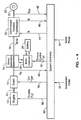
- an electric motor 24 is coupled to the input shaft 16 of the continuously variable transmission 18 so that it injects power in parallel with the drive train between engine 10 and continuously variable transmission 18.
- Electric motor 24 is powered by a battery 26, which would typically comprise a bank of batteries, ultra-capacitors or the like, such as those used in electric vehicles.
- Operation of electric motor 24 is controlled by a motor controller 28, which is a conventional electronic armature controller or the like, which is in turn controlled by a microprocessor- or other computer-based programmable system controller 30.
- electric motor 24 can vary and, while electric motor 24 can be a motor only, electric motor 24 is preferably a motor/generator that can also be used to charge battery 26. Therefore, all references to the terms "motor” or “motor controller” in the specification and claims are intended to encompass either a motor and a motor controller or a motor/generator and motor/generator controller, respectively. References herein made to "motor/generator” and “motor/generator controller” are for purposes of describing the preferred embodiment of the invention. Electric motor 24 would, for example, be a conventional DC or AC or switch reluctance or other torque controlled high power traction motor/generator used in hybrid and electric vehicles.
- a mechanical CVT 18 can be eliminated altogether and replaced by the motor (or motor/generator) and motor controller (or motor/generator controller) in combination with a generator (or generator/motor) and generator controller (or generator/motor controller) as will be discussed below with reference to FIG. 5 and FIG. 6 .
- system controller 30 processes a plurality of control and feedback signals.
- the primary input control signals are from the vehicle accelerator pedal 32 and brake pedal 34. It will be appreciated that other control signals may also be used for example, such as park, drive, performance and so forth.
- S DS S CAR ⁇ C
- S CAR is the speed of the vehicle and C is a constant dependent on the gear ratio of the final drive and tire radius for the vehicle.
- system controller 30 senses engine speed S E via speed signals 40, the ratio R via signals 46, and vehicle speed S CAR via signals 48.
- the system controller 30 may send an "on/off' signal to engine 10, but a separate starter motor is not needed; electric motor 24 can be used start engine 10 because it is coupled to engine output shaft 12 through clutch 14.
- the engine 10 may be turned “off” or idled when clutch 14 is opened.
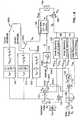
- the present invention can be extended to a series hybrid vehicle configuration as shown in which a generator 50 is used to provide charging capability for battery 26 as well as to provide a braking effect for engine 10 during deceleration.
- Operation of generator 50 is preferably controlled by a generator controller 52, which is a conventional electronic armature controller or the like.
- generator 50 is of a generator/motor type so that operation can force engine 10 to achieve the desired speed quickly, thus providing for fast overall engine response. Therefore, all references to the terms “generator” or “generator controller” in the specification and claims are intended to encompass either a generator and a generator controller or a generator/motor and generator/motor controller, respectively. References herein made to “generator/motor” and “generator/motor controller” are for purposes of describing the preferred embodiment of the invention.
- Generator 50 would, for example, he a conventional DC or AC or switch reluctance or other torque controlled high power traction generator/motor used in hybrid and electric vehicles.
- engine 10 can be operated at high torque but at a power necessary to provide steady cruise speed.
- the engine torque and power may be small compared with the electric motor/battery power.
- a mechanical CVT or automatic transmission 18 may be used as shown in FIG. 5 , or eliminated altogether as shown in FIG. 6 since generator 50 and motor (or motor/generator) 24 via the generator controller 52 and motor controller 28, respectively, together function as an electric CVT.
- generator 50 is used to control the engine power hy temporarily putting energy into, or taking energy out of, battery 26 based on the power commanded by the driver.
- the invention can also be applied to dual power parallel powertrain as shown.
- This embodiment provides torque from both the front wheels 58 of the vehicle 60 electrically from the electric motor (or motor/generator) 24 and the rear wheels 62 mechanically from engine 10 through clutch 12 and CVT 18.
- the block shown as CVT 18 could be a conventional continuously variable or automatic transmission.
- the CVT 18 is connected only to engine 10; the road and tires effectively connect the front and rear wheels together through the road 64, with the road 64 effectively acting as a shaft.
- the drive wheels may also be reversed, with the electric motor at the rear and the engine and CVT at the front of the vehicle.
- the electric motor controls the engine through the CVT, the output of which is controlled through the road.
- this configuration is effectively that of a parallel hybrid configuration and would be controlled using a hybrid of the embodiments shown in FIG. 4 and FIG. 5 .
- the electric motor 24 can once again control the overall force of the vehicle so that the concept of engine and vehicle control shown in FIG. 4 is accomplished.
- the engine can then operate on the IOL with modulating torque from the electric motor 24.
- the advantage of this system is a small engine-CVT system relative to the high power electric motor that can be used for high fuel efficiency and performance.
- system controller, 30 implements the control and sensing functions of the invention using conventional hardware and/or software.
- T the time constant of the filter
- S the Laplace transform of variable P EP or T E which is easily programmed by those skilled in the art
- R the ratio between engine speed and driveshaft speed
- R ⁇ the rate of change of ratio R
- C a conversion constant to convert vehicle speed to driveshaft speed
- S E engine speed
- S DS drive shaft speed
- S CAR vehicle speed
- K B is a gain value for scaling.
- the IOL E of the engine is obtained by testing the engine to determine the best efficiency and emissions at each speed.
- the IOL M and IRL are obtained by testing the electric motor/generator and battery system to obtain the most energy into the battery at each speed. Note that the IOL M is used when the vehicle is in the electric drive mode where the vehicle is operated, generally, below freeway speeds until the batteries are depleted to a predetermined state as described in U.S. Patent No. 5,842,534 .
- the control objective here is to drive the vehicle using electric energy until the internal combustion engine is turned “on” and then drive the vehicle with the internal combustion engine as much as possible, automatically supplementing the internal combustion engine with electric energy when needed to maintain operation of the engine along the IOL.
- energy may be put back into the batteries temporarily when the engine power is reduced in order to keep the engine on the IOL at all times in the hybrid mode. This kind of operation can significantly reduce emissions and increase engine efficiency.
- the control strategy of FIG. 8 will function with charge depletion HEV implementations as shown in my prior U.S. No. 5,842,534 as well as most conventional charge sustaining HEV implementations.
- the IOL is engine dependent, and is determined empirically from test data.
- the IOL is the line representing engine power output per speed that provides the best engine efficiency and low emissions. It will be appreciated, however, that the IOL could represent any desired engine operating condition at a particular engine speed. Since the power output varies as a function of speed and load on the engine, the present invention uses motor 24 as in FIG. 4 , or generator 50 and/or motor 24 in FIG. 5 and FIG. 6 , to vary the speed and power output of the engine to be on the IOL at all times when the engine is "on".
- system controller 30 senses the acceleration command A C from the accelerator pedal and the switches SW1 and SW2 shown in FIG. 8 go to the accelerator position.
- P C or +T C power or a positive torque is commanded by the driver ( P C or +T C ) in the electric vehicle mode determined by SW3 and SW4 as the case may be depending upon whether or not the system is operating in the power control region or the torque control region shown in FIG.
- the motor torque signal determined above is sent to motor controller 28 in FIG. 4 to vary the speed and power of engine 10 and to drive the car.
- engine speed S E (which may also be the same as the motor speed S M where they are on a common shaft) can be determined by applying a conversion constant C to the vehicle speed S CAR at 104 to get the speed S DS of driveshaft 20 of FIG. 4 (which is the output of CVT 18) and then multiplying the driveshaft speed S DS by the ratio R at 106 in FIG. 8 to give the engine speed S E .
- look-up tables containing the IOL entries for the hybrid mode, braking mode and the electric mode, respectively, are accessed to determine the ideal engine power or torque output level for the given speed. Then, at 110 for the hybrid mode, 118 for the braking mode or 130 for the electric mode, the output of the corresponding look-up table is compared with either the power P C (if in power control mode) or positive torque + T C (if in torque control mode) commanded by the driver with the accelerator pedal as sensed from accelerator pedal position A C to determine a power error P EP or a torque error T EP .
- P EP or T EP could be determined, for example, would be to use a potentiometer that produces an output signal in response to accelerator pedal position ( P C or T C , and subtracting the appropriately scaled P IOL or T IOL from the look-up tables.
- Transducers, digital to analog converters and/or analog to digital converters, could also be used as is conventional in the signal acquisition and processing art.
- the corresponding error signal is then used to affect the rate of change R ⁇ of the ratio R after filtering the signal at 112.
- CVT 18 of FIG. 4 thus responds in accordance with the adjustment of R ⁇ .
- An important aspect of the control system is the control of the rate of change of ratio R or R ⁇ .
- This is accomplished by filtering the error signal between the commanded power PC or torque TC and the IOL power or torque.
- the signal filtering which is in the form of K 1 • 1 TS + 1 is well known in the art of electrical engineering. It is understood that this filter is only representative of one form that may be placed at this point, and in practice the filter may include both linear and non-linear elements.
- the purpose of the filter is to allow the designer to control the ratio rate, R ⁇ . It is undesirable to change R quickly and, therefore, a filter is necessary to provide the desired system response.
- the values of K, and T are heuristically determined, as is the form of the filter (which is shown here as first order). Those skilled in the art will appreciate that filters of many other representations will work and can be selected depending on the desired response, and the scope of the present invention should not be limited by the use of this particular filter.
- system controller 30 senses the braking command B C from the brake pedal.
- the driver commands negative torque - T C
- the system is in a deceleration (regeneration) mode and the switches go to the brake position.
- control of the CVT and electric motor/generator reverses to produce a negative torque on the driveshaft, thus braking the vehicle.
- a mechanical backup brake (not shown) for use in emergencies, panic stops and parking.
- the operation of the braking circuit is similar to that of the accelerator circuit except for the use of the ideal regeneration line IRL, which reflects the highest efficiency for a given power for regenerating energy into the batteries by the electric motor/generator.
- the resultant change in electric motor/generator and engine torque again affect the vehicle dynamics at 102, to slow the car which affects motor and/or engine speed, vehicle deceleration and the ratio R at CVT 18.
- engine speed S E is used at 116 to access a look-up table containing entries representing the IRL , which is also an empirically determined table.
- the output of the look-up table is compared with the negative torque - T C commanded by the driver with the brake pedal as sensed from brake pedal position B C to determine the braking torque error T EB .
- the braking torque error signal T EB is then scaled by a value of K B through gain box 120 and used to affect the rate of change R ⁇ of the ratio R after filtering at 112. It should be appreciated that the filtering in the brake torque control can be different if desired and that gain box 120 may contain additional filters.
- FIG. 8 and FIG. 9 represent the controls for the configuration shown in FIG. 4 and, in principle, the controls for the configurations expressed in FIG. 5 through FIG. 7 or other hybrid electric drive systems.
- the configuration shown in FIG. 6 can be used directly with the control scheme shown in FIG. 8 and FIG. 9 discussed below since the mechanical CVT shown in FIG. 4 is simply replaced by its electrical equivalent.
- the generator/motor is used to control the engine along the IOL instead of the CVT.
- the electric motor torque T M overrides the engine torque T E with a negative torque to force the engine to slow down to the desired power level at point A .
- T M overrides the engine torque T E with a negative torque to force the engine to slow down to the desired power level at point A .
- a second and preferred method would be to use the motor/generator in a generator mode, thereby absorbing the necessary torque and returning energy to the batteries. This constitutes an acceleration/deceleration cycle by the accelerator pedal.
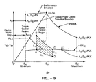
- FIG. 9 which divides the operating range into a torque control region and a power control region is preferable because of the nature of the CVT and the characteristics of the motor and engine.
- This boundary is shown as a line between the torque speed origin and the point A 1 , S 0 .
- Another boundary which separates electric operation from hybrid operation is shown in FIG. 9 as the vertical line at point S E minimum.
- This boundary is arbitrary and can consist of a curve or a series of steps or a vertical line from A 1 , S 0 to the speed axis at S 0 .
- the transition from torque control to power control should be seamless to the driver of the vehicle as well as when the engine is coupled on or off.
- the high power electric motor is used to provide this seamless transition.
- This point is the maximum allowed power to the electric motor. As the speed further increases, the maximum power of the motor is added to the increasing power of the engine. These powers are additive, but the torque decreases to the point A 2 ,S E MAX as the vehicle continues to accelerate.
- the electric motor maximum speed S M MAX and the gasoline engine maximum speed S E MAX are preferably the same.
- This point A 2 ,S E MAX will be maintained as the vehicle continues to accelerate and the CVT ratio R changes. The vehicle speed continues to increase until the load and friction drag become equal to the torque at A 2 ,S E MAX or Scar MAX is reached. The vehicle will then stop accelerating. Note that this will be the vehicle's top speed.
- This motor torque signal is transmitted to block 102. The power desired by the driver is then achieved instantly. If the accelerator pedal is held constant at this point over time, then the torque of the electric motor will decrease along a line of constant power along line L 2 in FIG. 9 , thus holding the power constant as the vehicle accelerates.
- This line L 2 represents the action of the feedback loop as designed in FIG.
- the car then will maintain this speed until the position of accelerator pedal is again changed. If the accelerator pedal is now reduced to the original position, the net torque will be reduced to point D , and speed will proceed back to point A along a constant power line L 4 . To accomplish this, the electric motor/generator must supply a negative torque to reach point D along line L 3 . This happens instantly. As the net torque and power proceeds along line L 4 , the electric motor/generator torque gradually approaches zero as the vehicle again begins to cruise when the accelerator position returns to A CA . Note that in this preferred mode the deceleration maneuver returns energy to the battery system described above, and the acceleration maneuver takes energy from the battery system while the engine continues to operate along the IOL.
- the throttle opening of the engine is set to provide the best efficiency for a given power along the IOL.
- the electric motor is used to force the engine to operate along the IOL and to provide correct transient response to the vehicle. Note that a large electric motor and a small engine is preferred, but the invention can also employ a large engine and small electric motor with slower response.
- the CVT provides the correct speed and power setting as quickly as dynamics and motor capacity allow.
- the battery capacity is then used to temporarily provide and absorb energy to allow the CVT to change ratio without detrimental effects on performance. It will further be appreciated that this is accomplished, in the preferred embodiment, by having the engine and the electric motor on the same shaft in the preferred embodiment.
- the present invention can take advantage of the electric motor in a common shaft hybrid electric power train in a way heretofore unknown.
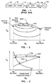
- the electric motor can be used to supplement and control the gasoline or diesel engine during both acceleration and deceleration of the vehicle, thus allowing the engine to run at optimum efficiency across its entire speed band with generally a fixed throttle setting or in an un-throttled state so as to maximize engine efficiency. This is not possible in a conventional continuously variable transmission system as discussed in FIG. 1 .
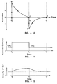
- control of the accelerator pedal provides instant torque compensation as well as power control in the steady state in the example power cycle described above.
- the power during the transition time from t 0 to t 1 is supplied from the battery pack in the preferred embodiment.
- the power absorbed during the transition time from t 1 to t 2 is fed back into the battery pack.
- the battery pack should be large enough to keep its internal resistance low, so that the modulation of the accelerator pedal uses a minimum percentage of the total energy to and from the battery pack, thus extending the range on a battery charge.
- the main battery pack can he charged off-board by stationary power plants if desired. This concept is especially important while the car is being driven at highway speeds because the power required may make gasoline or diesel more efficient to use than electricity. For city driving in the hybrid mode, this concept is also used to extend range.
- the IRL is a line determined by testing the motor/generator and battery system for the best efficiency for energy storage at each speed. After such testing procedure, an ideal line can he selected to connect all the best efficiency points yielding the IRL.
- the brake command Bc (at 34 in FIG. 8 ) represents a desired torque at the drive shaft or wheels of the car.
- the torque command is divided by the ratio R to obtain the equivalent torque at the CVT input 124.
- This input is compared with the torque along the IRL at the speed of the motor S M at this instant.
- the error is used to command R ⁇ through the gain block 120 and filter block 112.
- the ratio R of the transmission will change to seek the IRL via the feedback control system of blocks 102, 104, 106, 112, 116, 118 and 120. It is understood that this control system becomes ineffective when the ratio reaches its physical limits Rmin or Rmax in either acceleration or braking mode.
- the desired torque at the output of block 122 is sent to block 100 to compute the motor torque necessary to achieve the desired braking torque at the driveshaft and consequently the wheels of the car. Initially the torque at the motor is T C / R since R ⁇ is zero at the start of the maneuver.
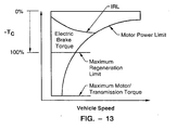
- the braking torque as a function of vehicle speed is shown in FIG. 13 .
- This figure shows the torque command T C for the drive shaft.
- the maximum allowable safe electrical regeneration braking torque is set at 100%. If more torque is required, the brake pedal then commands the standard hydraulic mechanical brakes, which are used for panic stops, to hold the car at zero speed and emergency and parking.
- this invention provides for simultaneous control of the acceleration of a vehicle and the torque and speed of the engine in a vehicle, and allows the engine to always operate at a best throttle or along the best efficiency (ideal speed/torque) operating line, thereby reducing the emissions of the engine and providing the best possible efficiency and lowest emissions, or operating the engine in accordance with any other desired operating characteristics. It also provides the possibility of operating the electric traction motor at its optimum efficiency during acceleration, braking and cruising when operating in the electric car mode. Furthermore, the invention described herein is application to "mild hybrids" as well as charge depletion hybrids described in patent, U.S. No. 5,842,534 .
Landscapes
- Engineering & Computer Science (AREA)
- Mechanical Engineering (AREA)
- Combustion & Propulsion (AREA)
- Chemical & Material Sciences (AREA)
- Transportation (AREA)
- General Engineering & Computer Science (AREA)
- Power Engineering (AREA)
- Automation & Control Theory (AREA)
- Electric Propulsion And Braking For Vehicles (AREA)
- Control Of Vehicle Engines Or Engines For Specific Uses (AREA)
- Hybrid Electric Vehicles (AREA)
- Control Of Transmission Device (AREA)
- Control Of Driving Devices And Active Controlling Of Vehicle (AREA)
Claims (19)
- Vorrichtung zur Steuerung der Leistung am Ausgang einer Brennkraftmaschine (10) vom Typ mit einem Elektromotor (24), der mit dem Ausgang des Motors gekoppelt ist, gekennzeichnet durch:(a) Steuerungseinrichtungen (30) zur Aufrechterhaltung der Leistungsabgabe des genannten Motors (10) im Wesentlichen entlang einer idealen Betriebskurve für den genannten Motor, wenn sich die Drehzahl des Motors verändert, wobei die genannte ideale Betriebskurve die Motorleistungsabgabe als eine Funktion der Motordrehzahl spezifiziert, wobei die genannte Motorleistungsabgabe im Wesentlichen entlang der genannten idealen Leistungsabgabekurve gehalten wird, indem die Drehmomentleistung des genannten Elektromotors (24) angepasst wird, und wodurch die Leistungsabgabe des genannten Motors (10) angepasst wird; und(b) wobei die genannten Steuerungseinrichtungen ferner so vorgesehen sind, dass sie die Leistungsabgabe des genannten Motors anpassen, in dem die Anpassungsrate der Übertragung des Übersetzungsverhältnisses eines kontinuierlich veränderlichen Getriebes (18), das durch den genannten Motor angetrieben wird, gesteuert wird, wobei das genannte kontinuierlich veränderliche Getriebe ein variables Übersetzungsverhältnis aufweist.
- Vorrichtung nach Anspruch 1, zur Steuerung der Leistung an dem Ausgang eines Motors (10), der mit dem genannten Getriebe (18) gekoppelt ist; wobei der genannte Elektromotor (24) zwischen dem genannten Motor und dem genannten Getriebe positioniert ist.
- Vorrichtung nach Anspruch 1 oder 2, wobei der genannte Motor (24) einen Generator/Motor umfasst.
- Vorrichtung nach Anspruch 3, wobei die genannte Steuerungseinrichtung (28) für einen Motor bereitgestellt ist, um das positive und negative Leistungsdrehmoment des genannten Generators/Motors anzupassen, um die Motorleistungsabgabe anzupassen.
- Vorrichtung nach Anspruch 1, zur Steuerung der Leistung an dem Ausgang eines Motors, wobei:(a) das genannte Getriebe (18) durch den genannten Motor (10) angetrieben wird, wobei das genannte Getriebe eine Ausgabe aufweist, welche ein erstes Rad (62) an einem ersten Ende eines Fahrzeugs antreibt;(b) der genannte Elektromotor (24) ein zweites Rad (58) an einem zweiten Ende des genannten Fahrzeugs antreibt und über eine Straßenoberfläche mit dem genannten Getriebe gekoppelt ist; und(c) die genannte Motorleistungsabgabe im Wesentlichen entlang der genannten idealen Leistungsabgabekurve gehalten wird, indem die Drehmomentleistung des genannten Elektromotors angepasst wird und die Rate der Veränderung des Übersetzungsverhältnisses angepasst wird und dadurch die Leistungsabgabe des genannten Motors angepasst wird.
- Vorrichtung nach Anspruch 3, wobei:(a) ein zweiter Elektromotor (50) mit der genannten Systemsteuereinheit (30) verbunden ist; und(b) die genannte Systemsteuereinheit (30) so konfiguriert ist, dass sie die Drehmomentleistung des genannten zweiten Elektromotors anpasst.
- Vorrichtung nach Anspruch 6, wobei der genannte zweite Elektromotor (50) einen Motor/Generator umfasst.
- Vorrichtung nach Anspruch 3 zur Steuerung der Leistung an dem Ausgang eines Motors, wobei:(a) eine Antriebswelle (16) mit dem genannten kontinuierlich veränderlichen Getriebe (18) gekoppelt ist;(b) der genannte Motor/Generator (24) mechanisch mit der genannten Antriebswelle gekoppelt ist;(c) die genannte Steuereinheit (28) für den Motor/Generator elektrisch mit dem genannten Motor/Generator verbunden ist;(d) ein zweiter Motor/Generator (50) mit dem genannten Motor (10) verbunden ist;(e) eine zweite Steuereinheit (52) für den Motor/Generator mit dem genannten zweiten Motor/Generator elektrisch verbunden ist; und wobei(f) eine Batterie (269 mit der genannten Steuereinheit für den Motor/Generator und mit der genannten zweiten Steuereinheit für den Motor/Generator elektrisch verbunden ist.
- Vorrichtung nach Anspruch 1, zur Regelung der Leistung an dem Ausgang eines Motors, wobei:(a) das genannte kontinuierlich veränderliche Getriebe (18) eine Ausgabe aufweist, welche ein erstes Rad (62) an einem ersten Ende eines Fahrzeugs antreibt;(b) der genannte Elektromotor (24) ein zweites Rad (58) an einem zweiten Ende des genannten Fahrzeugs antreibt; und(c) der genannte Elektromotor über eine Straßenoberfläche mit dem genannten Getriebe gekoppelt ist.
- Vorrichtung nach Anspruch 8, wobei die ideale Betriebskurve durch empirisches Testen des Motors, des Motors/Generators und des Batteriesystems bestimmt wird.
- Vorrichtung nach Anspruch 1, wobei diese ferner folgendes umfasst:(a) eine Motorsteuerung, die mechanisch mit der genannten Brennkraftmaschine (10) verbunden ist.
- Verfahren zur Steuerung der Leistung einer Brennkraftmaschine (10) mit einem Motor (24), der mit dem Ausgang des Motors gekoppelt ist, und mit einem kontinuierlich veränderlichen Getriebe (18), das mit dem Ausgang des Motors gekoppelt ist, gekennzeichnet durch:(a) das Bereitstellen einer Systemsteuereinheit (30), die mit dem Motor sowie mit dem Motor und dem Getriebe verbunden ist;(b) das Detektieren des Zustands von Motorleistung, Motordrehmoment und Übersetzungsverhältnis;(c) das Anpassen der Drehmomentleistung des genannten Motors, wodurch die Leistungsabgabe des genannten Motors angepasst wird, um die Motorleistungsabgabe im Wesentlichen entlang einer idealen Betriebskurve für den genannten Motor zu halten, wenn sich die Drehzahl des Motors verändert, wobei die genannte ideale Betriebskurve die Motorleistungsabgabe als eine Funktion der Motordrehzahl spezifiziert; und(d) das Steuern der Änderungsrate des genannten Übersetzungsverhältnisses des genannten Getriebes, wodurch die Leistungsabgabe des genannten Motors weiter angepasst wird.
- Verfahren nach Anspruch 12, wobei das Verfahren ferner folgendes umfasst:(a) das Bereitstellen eines Gaspedals (32), das die Leistungs- oder Drehmomentanforderungen über die Position des genannten Gaspedals der genannten Systemsteuereinheit (30) signalisiert;(b) das Empfangen des Beschleunigungssignals von der Position des genannten Gaspedals; und(c) das Anpassen der Drehmomentleistung des genannten Motors (24), wodurch die Leistungsabgabe des genannten Motors angepasst wird, wodurch die Leistungsabgabe des genannten Motors (10) als Reaktion auf das genannte Beschleunigungssignal angepasst wird.
- Verfahren nach Anspruch 12, wobei das Verfahren ferner folgendes umfasst:(a) das Bereitstellen eines Bremspedals (34), das ein Bremssignal an die genannte Systemsteuereinheit (30) bereitstellt;(b) das Empfangen eines Bremssignals anhand der Position des genannten Bremspedals;(c) das Anpassen der Drehmomentleistung des genannten Motors (24), wodurch die Leistungsabgabe des genannten Motors (10) als Reaktion auf das genannte Bremssignal angepasst wird.
- Verfahren nach Anspruch 12, wobei das Verfahren ferner das Bereitstellen eines Steuerungsbereichs umfasst, in dem die Gesamtleistung und die Drehmomentleistung an das Getriebe (18) durch den genannten Motor (24) bereitgestellt wird.
- Verfahren nach einem der Ansprüche 12 bis 15:(a) wobei es sich bei dein genannten Motor (24) um einen Motor/Generator handelt; und wobei das Verfahren folgendes umfasst:(b) das Zuführen von positivem oder negativem Drehmoment an den genannten Motor (10) mit dem genannten Motor/Generator.
- Verfahren nach Anspruch 16, wobei das Verfahren ferner folgendes umfasst:(a) das Bereitstellen eines zweiten Motors/Generators (50) und einer Batterie (26), die mit dem genannten Motor/Generator (24) elektrisch verbunden ist; und(b) das Steuern des Drehmoments des genannten zweiten Generators/Motors mit der genannten Systemsteuereinheit (30).
- Verfahren nach Anspruch 17, wobei das Verfahren ferner folgendes umfasst:(a) das mechanische Verbinden des genannten ersten Motors/Generators (24) mit dem genannten Getriebe (18); und(b) das mechanische Verbinden des genannten zweiten Generators/Motors (50) mit dem genannten Motor (10).
- Verfahren nach einem der Ansprüche 12 bis 16, wobei das Verfahren ferner folgendes umfasst:(a) das Antreiben eines ersten Rads (62) mit dem genannten Motor (10) und dem genannten Getriebe (18);(b) das Antreiben eines zweiten Rads mit dem genannten Motor (24); und(c) das Koppeln des genannten ersten Rads mit dem genannten zweiten Rad mit einer Straßenoberfläche.
Applications Claiming Priority (3)
| Application Number | Priority Date | Filing Date | Title |
|---|---|---|---|
| US63993 | 1998-04-21 | ||
| US09/063,993 US6054844A (en) | 1998-04-21 | 1998-04-21 | Control method and apparatus for internal combustion engine electric hybrid vehicles |
| PCT/US1999/009880 WO2000025417A1 (en) | 1998-04-21 | 1999-04-19 | Control method and apparatus for internal combustion engine electric hybrid vehicles |
Publications (3)
| Publication Number | Publication Date |
|---|---|
| EP1074087A1 EP1074087A1 (de) | 2001-02-07 |
| EP1074087A4 EP1074087A4 (de) | 2004-08-25 |
| EP1074087B1 true EP1074087B1 (de) | 2009-11-25 |
Family
ID=22052841
Family Applications (1)
| Application Number | Title | Priority Date | Filing Date |
|---|---|---|---|
| EP99925573A Expired - Lifetime EP1074087B1 (de) | 1998-04-21 | 1999-04-19 | Regelverfahren und vorrichtung für die brennkraftmaschine eines elektrischen hybridfahrzeuges |
Country Status (8)
| Country | Link |
|---|---|
| US (2) | US6054844A (de) |
| EP (1) | EP1074087B1 (de) |
| JP (2) | JP2002529043A (de) |
| AT (1) | ATE449714T1 (de) |
| AU (1) | AU4182799A (de) |
| CA (1) | CA2326165A1 (de) |
| DE (1) | DE69941692D1 (de) |
| WO (1) | WO2000025417A1 (de) |
Cited By (4)
| Publication number | Priority date | Publication date | Assignee | Title |
|---|---|---|---|---|
| DE102015222691A1 (de) | 2015-11-17 | 2017-05-18 | Volkswagen Aktiengesellschaft | Verfahren zum Steuern einer Antriebseinrichtung eines Hybridfahrzeuges und Hybridfahrzeug |
| DE102015222690A1 (de) | 2015-11-17 | 2017-05-18 | Volkswagen Aktiengesellschaft | Steuern einer Antriebseinrichtung eines Hybridfahrzeuges und Hybridfahrzeug |
| DE102015222692A1 (de) | 2015-11-17 | 2017-05-18 | Volkswagen Aktiengesellschaft | Betreiben einer Antriebseinrichtung eines Hybridfahrzeuges und Hybridfahrzeug |
| DE102015222694A1 (de) | 2015-11-17 | 2017-05-18 | Volkswagen Aktiengesellschaft | Betreiben einer Antriebseinrichtung eines Hybridfahrzeuges und Hybridfahrzeug |
Families Citing this family (242)
| Publication number | Priority date | Publication date | Assignee | Title |
|---|---|---|---|---|
| US6054844A (en) | 1998-04-21 | 2000-04-25 | The Regents Of The University Of California | Control method and apparatus for internal combustion engine electric hybrid vehicles |
| US6847189B2 (en) | 1995-05-31 | 2005-01-25 | The Regents Of The University Of California | Method for controlling the operating characteristics of a hybrid electric vehicle |
| US6551210B2 (en) | 2000-10-24 | 2003-04-22 | Motion Technologies, Llc. | Continuously variable transmission |
| JP3438589B2 (ja) * | 1998-06-04 | 2003-08-18 | 日産自動車株式会社 | 車両の駆動力制御装置 |
| US6554088B2 (en) | 1998-09-14 | 2003-04-29 | Paice Corporation | Hybrid vehicles |
| US6209672B1 (en) * | 1998-09-14 | 2001-04-03 | Paice Corporation | Hybrid vehicle |
| US6338391B1 (en) | 1999-03-01 | 2002-01-15 | Paice Corporation | Hybrid vehicles incorporating turbochargers |
| JP3383231B2 (ja) * | 1998-12-17 | 2003-03-04 | 本田技研工業株式会社 | ハイブリッド車両の制御装置 |
| US6885920B2 (en) * | 1999-07-30 | 2005-04-26 | Oshkosh Truck Corporation | Control system and method for electric vehicle |
| US7729831B2 (en) * | 1999-07-30 | 2010-06-01 | Oshkosh Corporation | Concrete placement vehicle control system and method |
| US6757597B2 (en) * | 2001-01-31 | 2004-06-29 | Oshkosh Truck | A/C bus assembly for electronic traction vehicle |
| JP3654074B2 (ja) * | 1999-08-27 | 2005-06-02 | トヨタ自動車株式会社 | 複数の原動機を備えた車両の制御装置 |
| US6825575B1 (en) * | 1999-09-28 | 2004-11-30 | Borealis Technical Limited | Electronically controlled engine generator set |
| US7905813B2 (en) * | 1999-09-28 | 2011-03-15 | Borealis Technical Limited | Electronically controlled engine generator set |
| JP4069556B2 (ja) * | 1999-10-07 | 2008-04-02 | トヨタ自動車株式会社 | 動力出力装置の制御方法 |
| US6239502B1 (en) * | 1999-11-22 | 2001-05-29 | Bae Systems Controls | Phase change assisted heat sink |
| DE10008299A1 (de) * | 2000-02-23 | 2001-09-27 | Daimler Chrysler Ag | Verfahren zum Betreiben eines elektrischen Generator/Motor-Systems |
| EP1129890B1 (de) * | 2000-03-01 | 2008-01-02 | Hitachi, Ltd. | Elektrisches Generatorsystem für Fahrzeuge und sein Regelverfahren |
| US6394208B1 (en) * | 2000-03-30 | 2002-05-28 | Ford Global Technologies, Inc. | Starter/alternator control strategy to enhance driveability of a low storage requirement hybrid electric vehicle |
| GB0016182D0 (en) | 2000-06-30 | 2000-08-23 | Lucas Industries Ltd | Controller for a continuously variable transmission |
| US6449537B1 (en) * | 2000-10-27 | 2002-09-10 | Ford Motor Company | Energy control strategy for a hybrid electric vehicle |
| US6543565B1 (en) * | 2000-11-10 | 2003-04-08 | Ford Motor Company | Method and system for collecting regenerative braking energy in a parallel hybrid electric vehicle |
| US6971461B2 (en) * | 2000-11-13 | 2005-12-06 | Honda Giken Kogyo Kabushiki Kaisha | Front and rear wheel drive vehicle and control device for controlling same |
| US7774108B2 (en) * | 2000-11-14 | 2010-08-10 | Honda Giken Kogyo Kabushiki Kaisha | Front and rear wheel drive vehicle |
| GB0028598D0 (en) * | 2000-11-23 | 2001-01-10 | Ricardo Consulting Eng | Improvements in hybrid power sources |
| US6442455B1 (en) * | 2000-12-21 | 2002-08-27 | Ford Global Technologies, Inc. | Adaptive fuel strategy for a hybrid electric vehicle |
| DE10064188A1 (de) * | 2000-12-22 | 2002-07-11 | Magnet Motor Gmbh | Verfahren zum Betreiben eines nichtschienengebundenen Land-Kraftfahrzeugs mit Verbrennungsmotor-Generator-Einheit und Antriebs-Elektromotor, und derartiges Kraftfahrzeug |
| CN100362722C (zh) * | 2001-01-03 | 2008-01-16 | 加利福尼亚大学董事会 | 混合电动车辆及用于控制混合电动车辆的方法及装置 |
| US7379797B2 (en) * | 2001-01-31 | 2008-05-27 | Oshkosh Truck Corporation | System and method for braking in an electric vehicle |
| US7277782B2 (en) | 2001-01-31 | 2007-10-02 | Oshkosh Truck Corporation | Control system and method for electric vehicle |
| DE60201615T8 (de) * | 2001-03-14 | 2006-08-24 | Conception Et Development Michelin S.A. | Fahrzeug mit Super-Kondensator zur Bremsenergie-Rückgewinnung |
| US20060005736A1 (en) * | 2001-03-27 | 2006-01-12 | General Electric Company | Hybrid energy off highway vehicle electric power management system and method |
| US7137344B2 (en) * | 2001-03-27 | 2006-11-21 | General Electric Company | Hybrid energy off highway vehicle load control system and method |
| US7185591B2 (en) * | 2001-03-27 | 2007-03-06 | General Electric Company | Hybrid energy off highway vehicle propulsion circuit |
| US9193268B2 (en) | 2001-03-27 | 2015-11-24 | General Electric Company | Hybrid energy power management system and method |
| US6615118B2 (en) * | 2001-03-27 | 2003-09-02 | General Electric Company | Hybrid energy power management system and method |
| US7430967B2 (en) * | 2001-03-27 | 2008-10-07 | General Electric Company | Multimode hybrid energy railway vehicle system and method |
| US7448328B2 (en) * | 2001-03-27 | 2008-11-11 | General Electric Company | Hybrid energy off highway vehicle electric power storage system and method |
| US7231877B2 (en) * | 2001-03-27 | 2007-06-19 | General Electric Company | Multimode hybrid energy railway vehicle system and method |
| US9151232B2 (en) | 2001-03-27 | 2015-10-06 | General Electric Company | Control system and method |
| KR100884970B1 (ko) * | 2001-04-26 | 2009-02-23 | 모션 테크놀로지즈 엘엘씨 | 연속 가변 변속기용 스핀들 지지체와 동력 조절기 조립체및 그 제조방법 |
| US6622069B1 (en) * | 2001-05-05 | 2003-09-16 | Curtis Instruments, Inc. | Automatic motor adjustment for differentially steered dual electric motor system |
| US6603215B2 (en) * | 2001-05-24 | 2003-08-05 | Ford Global Technologies, Llc | Hybrid electric vehicle control strategy while traveling in reverse |
| JP3519061B2 (ja) * | 2001-06-08 | 2004-04-12 | 三菱電機株式会社 | 車両用回転電機 |
| US6837323B2 (en) | 2001-06-18 | 2005-01-04 | Visteon Global Technologies Inc. | Variable shift schedule control |
| US6581705B2 (en) * | 2001-06-29 | 2003-06-24 | Ford Global Technologies, Llc | Method for starting an engine in a parallel hybrid electric vehicle |
| US6553287B1 (en) | 2001-10-19 | 2003-04-22 | Ford Global Technologies, Inc. | Hybrid electric vehicle control strategy to achieve maximum wide open throttle acceleration performance |
| DE10157669A1 (de) * | 2001-11-24 | 2003-06-05 | Bosch Gmbh Robert | Verfahren zur Steuerung des Betriebsverhaltens eines Hybridantriebes eines Fahrzeuges |
| US7302320B2 (en) | 2001-12-21 | 2007-11-27 | Oshkosh Truck Corporation | Failure mode operation for an electric vehicle |
| US7254468B2 (en) * | 2001-12-21 | 2007-08-07 | Oshkosh Truck Corporation | Multi-network control system for a vehicle |
| US6827167B2 (en) * | 2002-03-28 | 2004-12-07 | Ford Global Technologies, Llc | Hybrid electric vehicle torque distribution |
| US7520354B2 (en) * | 2002-05-02 | 2009-04-21 | Oshkosh Truck Corporation | Hybrid vehicle with combustion engine/electric motor drive |
| US6842673B2 (en) * | 2002-06-05 | 2005-01-11 | Visteon Global Technologies, Inc. | Engine engagement control for a hybrid electric vehicle |
| JP3915699B2 (ja) * | 2002-12-27 | 2007-05-16 | アイシン・エィ・ダブリュ株式会社 | ハイブリッド車輌の制御装置 |
| US7233088B2 (en) * | 2003-01-17 | 2007-06-19 | Magnetic Torque International, Ltd. | Torque converter and system using the same |
| US7268454B2 (en) * | 2003-01-17 | 2007-09-11 | Magnetic Torque International, Ltd. | Power generating systems |
| US6777904B1 (en) | 2003-02-25 | 2004-08-17 | Ford Global Technologies, Llc | Method and system for controlling a motor |
| US7011600B2 (en) | 2003-02-28 | 2006-03-14 | Fallbrook Technologies Inc. | Continuously variable transmission |
| US6998727B2 (en) * | 2003-03-10 | 2006-02-14 | The United States Of America As Represented By The Administrator Of The Environmental Protection Agency | Methods of operating a parallel hybrid vehicle having an internal combustion engine and a secondary power source |
| JP2006523292A (ja) * | 2003-03-19 | 2006-10-12 | ザ リージェンツ オブ ザ ユニヴァーシティー オブ カリフォルニア | 無段変速機における比の変化率を制御する方法およびシステム |
| DE10337002A1 (de) * | 2003-08-12 | 2005-03-17 | Zf Friedrichshafen Ag | Verfahren zur Steuerung der Antriebsleistungsverteilung in einem Kraftfahrzeug mit Hybridantrieb |
| US7143851B2 (en) * | 2003-09-10 | 2006-12-05 | Ford Global Technologies, Llc | Method for controlling a wheel drive system of a hybrid vehicle |
| US6876098B1 (en) * | 2003-09-25 | 2005-04-05 | The United States Of America As Represented By The Administrator Of The Environmental Protection Agency | Methods of operating a series hybrid vehicle |
| US7237495B2 (en) * | 2003-10-02 | 2007-07-03 | Cnh America Llc | Method and apparatus for blocking air from a seed planter |
| US7030580B2 (en) * | 2003-12-22 | 2006-04-18 | Caterpillar Inc. | Motor/generator transient response system |
| US7173344B2 (en) * | 2004-04-19 | 2007-02-06 | Tai-Her Yang | Series & parallel combined dual power drive system |
| US20050230975A1 (en) * | 2004-04-19 | 2005-10-20 | Tai-Her Yang | Series and parallel combined dual power drive system |
| DE102004025830B4 (de) * | 2004-05-24 | 2024-06-20 | Volkswagen Ag | Verfahren zum Betrieb eines Hybridfahrzeugs |
| US20060010844A1 (en) * | 2004-06-30 | 2006-01-19 | Self Guided Systems, L.L.C. | Unmanned utility vehicle |
| DE102004036581A1 (de) * | 2004-07-28 | 2006-03-23 | Robert Bosch Gmbh | Verfahren zum Betreiben eines Hybridantriebs und Vorrichtung zur Durchführung des Verfahrens |
| US7273439B2 (en) * | 2004-07-31 | 2007-09-25 | Ford Global Technologies, Llc | Strategy for mapping motor speed to calculate driver power demand in a hybrid electric vehicle |
| JP4481103B2 (ja) * | 2004-08-10 | 2010-06-16 | 本田技研工業株式会社 | 車両の発電制御装置、及び、その装置を搭載した車両 |
| US20060059880A1 (en) * | 2004-09-13 | 2006-03-23 | Angott Paul G | Unmanned utility vehicle |
| US7439711B2 (en) * | 2004-09-27 | 2008-10-21 | Oshkosh Corporation | Energy storage device including a status indicator |
| AU2005294611B2 (en) | 2004-10-05 | 2011-10-06 | Fallbrook Intellectual Property Company Llc | Continuously variable transmission |
| DE102004053948A1 (de) * | 2004-11-09 | 2006-06-01 | Daimlerchrysler Ag | Steuerung des Betriebsmodus eines Fahrzeuges mit Hybridantrieb |
| EP1813729B1 (de) * | 2004-11-17 | 2017-04-19 | Komatsu Ltd. | Rotationssteuervorrichtung und baumaschine |
| EP1666321A1 (de) * | 2004-12-06 | 2006-06-07 | Ford Global Technologies, LLC, A subsidary of Ford Motor Company | Verfahren zum Bremsen eines Fahrzeugs, Bremsvorrichtung und Fahrzeug mit einer Bremsvorrichtung |
| ITMI20050652A1 (it) * | 2005-04-15 | 2006-10-16 | Altra S P A | Dispositivo per l'incremento temporaneo dell'accelerazione di un motore termico e metodo per l'esercizio di detto dispositivo |
| DE602005008916D1 (de) * | 2005-04-18 | 2008-09-25 | Fiat Ricerche | Integriertes System zur Kontrolle des Antriebsstranges eines Kraftfahrzeugs |
| DE102005017965A1 (de) * | 2005-04-19 | 2006-10-26 | Cristobal Guzman | Über den Kraftstoffverbrauch gesteuertes Kraftfahrzeug |
| US20070017718A1 (en) * | 2005-07-20 | 2007-01-25 | Chrobak Dennis S | Power systems for transportation and residential uses |
| DE102005047653B4 (de) * | 2005-10-05 | 2021-08-19 | Volkswagen Ag | Hybridantriebseinheit mit Niedertemperatur-Kreislauf |
| DE102005051382A1 (de) * | 2005-10-27 | 2007-05-10 | Zf Friedrichshafen Ag | Hybridantrieb und Verfahren zu dessen Betrieb |
| US7632203B2 (en) | 2005-10-28 | 2009-12-15 | Fallbrook Technologies Inc. | Electromotive drives |
| US7344472B2 (en) * | 2005-10-31 | 2008-03-18 | Caterpillar Inc. | Power system |
| KR100705137B1 (ko) * | 2005-11-15 | 2007-04-09 | 현대자동차주식회사 | 하이브리드차량의 운전 모드 판단 방법 |
| US11267338B2 (en) | 2005-11-17 | 2022-03-08 | Invently Automotive Inc. | Electric vehicle power management system |
| US11279234B2 (en) | 2005-11-17 | 2022-03-22 | Invently Automotive Inc. | Vehicle power management system |
| US11351863B2 (en) | 2005-11-17 | 2022-06-07 | Invently Automotive Inc. | Vehicle power management system |
| US11186173B2 (en) | 2005-11-17 | 2021-11-30 | Invently Automotive Inc. | Electric vehicle power management system |
| US11285810B2 (en) | 2005-11-17 | 2022-03-29 | Invently Automotive Inc. | Vehicle power management system |
| US11186174B2 (en) | 2005-11-17 | 2021-11-30 | Invently Automotive Inc. | Vehicle power management system |
| US8712650B2 (en) | 2005-11-17 | 2014-04-29 | Invent.Ly, Llc | Power management systems and designs |
| US11279233B2 (en) | 2005-11-17 | 2022-03-22 | Invently Automotive Inc. | Electric vehicle power management system |
| US11225144B2 (en) | 2005-11-17 | 2022-01-18 | Invently Automotive Inc. | Vehicle power management system |
| US10882399B2 (en) | 2005-11-17 | 2021-01-05 | Invently Automotive Inc. | Electric vehicle power management system |
| US8972161B1 (en) | 2005-11-17 | 2015-03-03 | Invent.Ly, Llc | Power management systems and devices |
| US11186175B2 (en) | 2005-11-17 | 2021-11-30 | Invently Automotive Inc. | Vehicle power management system |
| US11370302B2 (en) | 2005-11-17 | 2022-06-28 | Invently Automotive Inc. | Electric vehicle power management system |
| US11254211B2 (en) | 2005-11-17 | 2022-02-22 | Invently Automotive Inc. | Electric vehicle power management system |
| US11345236B2 (en) | 2005-11-17 | 2022-05-31 | Invently Automotive Inc. | Electric vehicle power management system |
| US11325468B2 (en) | 2005-11-17 | 2022-05-10 | Invently Automotive Inc. | Vehicle power management system |
| US11084377B2 (en) | 2005-11-17 | 2021-08-10 | Invently Automotive Inc. | Vehicle power management system responsive to voice commands from a Gps enabled device |
| US7925426B2 (en) * | 2005-11-17 | 2011-04-12 | Motility Systems | Power management systems and devices |
| US11180025B2 (en) | 2005-11-17 | 2021-11-23 | Invently Automotive Inc. | Electric vehicle power management system |
| US11214144B2 (en) | 2005-11-17 | 2022-01-04 | Invently Automotive Inc. | Electric vehicle power management system |
| US11247564B2 (en) | 2005-11-17 | 2022-02-15 | Invently Automotive Inc. | Electric vehicle power management system |
| US11230190B2 (en) | 2005-11-17 | 2022-01-25 | Invently Automotive Inc. | Electric vehicle power management system |
| US11207980B2 (en) | 2005-11-17 | 2021-12-28 | Invently Automotive Inc. | Vehicle power management system responsive to traffic conditions |
| US11220179B2 (en) | 2005-11-17 | 2022-01-11 | Invently Automotive Inc. | Vehicle power management system determining route segment length |
| US11390165B2 (en) | 2005-11-17 | 2022-07-19 | Invently Automotive Inc. | Electric vehicle power management system |
| US11267339B2 (en) | 2005-11-17 | 2022-03-08 | Invently Automotive Inc. | Vehicle power management system |
| US11207981B2 (en) | 2005-11-17 | 2021-12-28 | Invently Automotive Inc. | Vehicle power management system |
| EP1954959B1 (de) | 2005-11-22 | 2013-05-15 | Fallbrook Intellectual Property Company LLC | Stufenlos verstellbares getriebe |
| CA2632751C (en) | 2005-12-09 | 2015-01-13 | Fallbrook Technologies Inc. | Continuously variable transmission |
| US20070182245A1 (en) * | 2005-12-12 | 2007-08-09 | Ducharme Leonard A | Hydraulic braking system that provides acceleration assistance and battery recharging |
| TWI287513B (en) * | 2005-12-19 | 2007-10-01 | Ind Tech Res Inst | Hybrid power system for vehicle |
| DE102005062869A1 (de) * | 2005-12-29 | 2007-07-05 | Robert Bosch Gmbh | Verfahren zur Vereinfachung der Momentenüberwachung, insbesondere bei Hybridantrieben |
| EP1811202A1 (de) | 2005-12-30 | 2007-07-25 | Fallbrook Technologies, Inc. | Stufenloses Getriebe |
| US7882762B2 (en) | 2006-01-30 | 2011-02-08 | Fallbrook Technologies Inc. | System for manipulating a continuously variable transmission |
| DE102006005477B4 (de) * | 2006-02-03 | 2007-10-11 | Veit Wilhelm | Vorrichtung zur Erzeugung von Strom, sowie Kraftfahrzeug mit Elektroantrieb und solcher Vorrichtung |
| JP4217916B2 (ja) * | 2006-02-15 | 2009-02-04 | 三菱ふそうトラック・バス株式会社 | ハイブリッド電気自動車の制御装置 |
| US7543665B2 (en) * | 2006-03-31 | 2009-06-09 | Caterpillar Inc. | Power system |
| DE102006019031A1 (de) * | 2006-04-25 | 2007-10-31 | Volkswagen Ag | Verfahren zur Momentensteuerung einer Hybridantriebseinheit sowie Hybridantriebseinheit |
| EP2021219B1 (de) * | 2006-05-09 | 2013-03-27 | Azure Dynamics, Inc. | Verfahren und vorrichtung zur reduzierung von stickoxidemissionen in generatormaschinensatzsystemen |
| US7309938B1 (en) * | 2006-05-31 | 2007-12-18 | Smith Kelly S | Rotary power converter |
| US8139109B2 (en) | 2006-06-19 | 2012-03-20 | Oshkosh Corporation | Vision system for an autonomous vehicle |
| US8947531B2 (en) | 2006-06-19 | 2015-02-03 | Oshkosh Corporation | Vehicle diagnostics based on information communicated between vehicles |
| ES2433373T3 (es) * | 2006-06-26 | 2013-12-10 | Mosaid Technologies Inc. | Procedimiento, aparatos, señales y medios, para la selección de las condiciones de funcionamiento de un grupo generador |
| EP2038531A4 (de) | 2006-06-26 | 2012-01-25 | Fallbrook Technologies Inc | Stufenlos einstellbare übertragung |
| US7329960B1 (en) * | 2006-07-26 | 2008-02-12 | General Electric Company | System and method for propelling a large land-based vehicle using a dual function brushless dynamoelectric machine |
| US7819220B2 (en) | 2006-07-28 | 2010-10-26 | Polaris Industries Inc. | Side-by-side ATV |
| US8827028B2 (en) | 2006-07-28 | 2014-09-09 | Polaris Industries Inc. | Side-by-side ATV |
| US7826939B2 (en) * | 2006-09-01 | 2010-11-02 | Azure Dynamics, Inc. | Method, apparatus, signals, and medium for managing power in a hybrid vehicle |
| PL2089642T3 (pl) | 2006-11-08 | 2013-09-30 | Fallbrook Ip Co Llc | Generator siły zaciskającej |
| US7909968B2 (en) * | 2006-11-13 | 2011-03-22 | Advanced R F Design, L.L.C. | Apparatus and method for the electrolysis of water |
| US7762218B2 (en) * | 2007-11-12 | 2010-07-27 | Advanced R F Designs, L.L.C. | Internal combustion engine using combustible gases produced by the electrolysis of water, and vehicle comprising same |
| WO2008063967A2 (en) * | 2006-11-13 | 2008-05-29 | Advanced R F Design, Llc | Electrolysis apparatus, internal combustion engine comprising the electrolysis apparatus, and vehicle comprising the internal combustion engine |
| JP4222414B2 (ja) * | 2006-12-04 | 2009-02-12 | トヨタ自動車株式会社 | 動力出力装置、それを備えたハイブリッド自動車、および動力出力装置の制御方法 |
| WO2008095116A2 (en) * | 2007-02-01 | 2008-08-07 | Fallbrook Technologies, Inc. | System and methods for control of transmission and/or prime mover |
| US20100093479A1 (en) | 2007-02-12 | 2010-04-15 | Fallbrook Technologies Inc. | Continuously variable transmissions and methods therefor |
| WO2008101070A2 (en) | 2007-02-16 | 2008-08-21 | Fallbrook Technologies Inc. | Infinitely variable transmissions, continuously variable transmissions, methods, assemblies, subassemblies, and components therefor |
| US20100025130A1 (en) * | 2007-03-01 | 2010-02-04 | Guilin Geely Stars Oil-Electric Hybrid Engine Co. | Fuel engine servo loading device and optimal efficiency operating control method thereof |
| EP2142826B1 (de) | 2007-04-24 | 2015-10-28 | Fallbrook Intellectual Property Company LLC | Elektrische zugvorrichtungen |
| DE102007020196A1 (de) * | 2007-04-28 | 2008-10-30 | Voith Patent Gmbh | Verfahren zur Regelung des Ladezustandes eines Energiespeicher für ein Fahrzeug mit Hybridantrieb |
| US8007401B2 (en) * | 2007-05-02 | 2011-08-30 | Nissan Motor Co., Ltd. | Hybrid vehicle drive control apparatus and method |
| WO2008154437A1 (en) | 2007-06-11 | 2008-12-18 | Fallbrook Technologies Inc. | Continuously variable transmission |
| CN103697120B (zh) | 2007-07-05 | 2017-04-12 | 福博科技术公司 | 无级变速器 |
| JP2009023614A (ja) * | 2007-07-23 | 2009-02-05 | Toyota Motor Corp | 車両用動力伝達装置の制御装置 |
| US8249766B2 (en) * | 2007-11-05 | 2012-08-21 | GM Global Technology Operations LLC | Method of determining output torque limits of a hybrid transmission operating in a fixed gear operating range state |
| CN103939602B (zh) | 2007-11-16 | 2016-12-07 | 福博科知识产权有限责任公司 | 用于变速传动装置的控制器 |
| KR100901558B1 (ko) | 2007-11-21 | 2009-06-08 | 현대자동차주식회사 | 하이브리드 차량용 엔진의 연속토크 제어방법 |
| CN102317146B (zh) | 2007-12-21 | 2015-11-25 | 福博科知识产权有限责任公司 | 自动传动装置及用于其的方法 |
| WO2009111328A1 (en) | 2008-02-29 | 2009-09-11 | Fallbrook Technologies Inc. | Continuously and/or infinitely variable transmissions and methods therefor |
| US8317651B2 (en) | 2008-05-07 | 2012-11-27 | Fallbrook Intellectual Property Company Llc | Assemblies and methods for clamping force generation |
| US8535199B2 (en) | 2008-06-06 | 2013-09-17 | Fallbrook Intellectual Property Company Llc | Infinitely variable transmissions, continuously variable transmissions, methods, assemblies, subassemblies, and components therefor |
| CN107246463A (zh) | 2008-06-23 | 2017-10-13 | 福博科知识产权有限责任公司 | 无级变速器 |
| US8639430B2 (en) | 2008-07-03 | 2014-01-28 | Fuel Saving Technologies, Llc | Energy conservation systems and methods |
| US7983830B2 (en) | 2008-07-03 | 2011-07-19 | Fuel Saving Technologies, Llc | Fuel conservation systems and methods |
| US8676415B2 (en) * | 2008-07-21 | 2014-03-18 | Ford Global Technologies, Llc | Engine power demand load-leveling for a hybrid electric vehicle |
| CA2732668C (en) | 2008-08-05 | 2017-11-14 | Fallbrook Technologies Inc. | Methods for control of transmission and prime mover |
| US8469856B2 (en) | 2008-08-26 | 2013-06-25 | Fallbrook Intellectual Property Company Llc | Continuously variable transmission |
| DE102008042132A1 (de) * | 2008-09-16 | 2010-03-18 | Robert Bosch Gmbh | Verfahren und Vorrichtung zum Betreiben eines Hybridantriebes für ein Fahrzeug |
| EP2362840A1 (de) * | 2008-09-26 | 2011-09-07 | Arb Greenpower, Llc | Hybrides energieumwandlungssystem |
| DE102008042544A1 (de) * | 2008-10-01 | 2010-04-08 | Robert Bosch Gmbh | Verfahren zum Betreiben eines Fahrzeugs mit einem hybriden Motorsystem sowie Motorsystem und Fahrzeug |
| US8167759B2 (en) | 2008-10-14 | 2012-05-01 | Fallbrook Technologies Inc. | Continuously variable transmission |
| US8225608B2 (en) * | 2008-11-04 | 2012-07-24 | GM Global Technology Operations LLC | Hybrid powertrain and method for controlling a hybrid powertrain |
| US9764726B2 (en) | 2009-01-02 | 2017-09-19 | Ford Global Technologies, Llc | Methods and systems for assisted direct start control |
| US9002600B2 (en) * | 2009-01-02 | 2015-04-07 | Ford Global Technologies, Llc | Methods and systems for engine shut-down control |
| US8473172B2 (en) * | 2009-01-02 | 2013-06-25 | Ford Global Technologies, Llc | System and methods for assisted direct start control |
| US7857080B2 (en) * | 2009-01-19 | 2010-12-28 | Hitachi Automotive Products (Usa), Inc. | System for selectively consuming and storing electrical energy in a hybrid vehicle |
| US20100240491A1 (en) * | 2009-03-17 | 2010-09-23 | Parag Vyas | System for vehicle propulsion having and method of making same |
| US8535200B2 (en) * | 2009-03-17 | 2013-09-17 | General Electric Company | Vehicle propulsion system having a continuously variable transmission and method of making same |
| EP4006381B1 (de) | 2009-04-16 | 2023-08-02 | Fallbrook Intellectual Property Company LLC | Stufenlos verstellbares kugelplanetengetriebe |
| JP5381422B2 (ja) * | 2009-07-03 | 2014-01-08 | トヨタ自動車株式会社 | 内燃機関の制御装置 |
| US7836986B1 (en) | 2009-07-07 | 2010-11-23 | Marsaili Gillecriosd | Throttle-free transmissionless hybrid vehicle |
| US8672069B2 (en) * | 2009-08-25 | 2014-03-18 | Deere & Company | Hybrid vehicle with multiple electric drive systems |
| CN101648562B (zh) * | 2009-09-04 | 2012-10-24 | 奇瑞汽车股份有限公司 | 电动汽车无级变速器的速比控制方法 |
| US9187083B2 (en) | 2009-09-16 | 2015-11-17 | Polaris Industries Inc. | System and method for charging an on-board battery of an electric vehicle |
| EP2308708B1 (de) * | 2009-09-16 | 2016-08-17 | swissauto powersport llc | Elektrofahrzeug mit Reichweitenverlängerung |
| US8783396B2 (en) * | 2010-01-21 | 2014-07-22 | Epower Engine Systems, Llc | Hydrocarbon fueled-electric series hybrid propulsion systems |
| US8512195B2 (en) | 2010-03-03 | 2013-08-20 | Fallbrook Intellectual Property Company Llc | Infinitely variable transmissions, continuously variable transmissions, methods, assemblies, subassemblies, and components therefor |
| US20110246012A1 (en) * | 2010-04-05 | 2011-10-06 | Continental Automotive Systems, Inc. | Intelligent regenerative braking utilizing environmental data |
| US8337352B2 (en) | 2010-06-22 | 2012-12-25 | Oshkosh Corporation | Electromechanical variable transmission |
| US8549838B2 (en) | 2010-10-19 | 2013-10-08 | Cummins Inc. | System, method, and apparatus for enhancing aftertreatment regeneration in a hybrid power system |
| US8888643B2 (en) | 2010-11-10 | 2014-11-18 | Fallbrook Intellectual Property Company Llc | Continuously variable transmission |
| US8400112B2 (en) * | 2010-11-10 | 2013-03-19 | Ford Global Technologies, Llc | Method for managing power limits for a battery |
| US8742701B2 (en) | 2010-12-20 | 2014-06-03 | Cummins Inc. | System, method, and apparatus for integrated hybrid power system thermal management |
| US8698348B2 (en) | 2011-01-10 | 2014-04-15 | Ford Global Technologies, Llc | System and method for managing a power source in a vehicle |
| CN117048579A (zh) | 2011-01-13 | 2023-11-14 | 卡明斯公司 | 用于控制混合动力传动系中的功率输出分布的系统、方法和装置 |
| WO2012098680A1 (ja) * | 2011-01-21 | 2012-07-26 | トヨタ自動車株式会社 | 車両制御装置 |
| JP5188593B2 (ja) * | 2011-03-31 | 2013-04-24 | 株式会社小松製作所 | 発電電動機の冷却構造及び発電電動機 |
| CA2830929A1 (en) | 2011-04-04 | 2012-10-11 | Fallbrook Intellectual Property Company Llc | Auxiliary power unit having a continuously variable transmission |
| US9132725B2 (en) | 2011-05-09 | 2015-09-15 | Cummins Inc. | Vehicle and hybrid drive system |
| CA2836671C (en) * | 2011-06-09 | 2015-05-19 | Prevost, Une Division De Groupe Volvo Canada Inc. | Hybrid vehicle |
| US20130065718A1 (en) * | 2011-09-08 | 2013-03-14 | Ford Global Technologies, Llc | Counter-Rotation Electric Machine |
| US8855844B2 (en) * | 2011-10-11 | 2014-10-07 | Robert Bosch Gmbh | System and method for optimal deceleration of a vehicle using regenerative braking |
| DE102011084322A1 (de) * | 2011-10-12 | 2013-04-18 | Robert Bosch Gmbh | Anordnung mit einer elektrisch betriebenen Achse für einen Allradantrieb eines Kraftfahrzeugs |
| EP2769071B1 (de) | 2011-10-19 | 2018-08-15 | Fuel Saving Technologies, Inc. | Energieeinsparungssysteme und verfahren |
| JP5674963B2 (ja) * | 2011-12-14 | 2015-02-25 | 三菱電機株式会社 | ハイブリッド車両の発電機制御装置 |
| US9020670B2 (en) * | 2011-12-21 | 2015-04-28 | Ford Global Technologies, Llc | Hybrid electric vehicle and method for smooth engine operation with fixed throttle position |
| CA2861889A1 (en) | 2012-01-23 | 2013-08-01 | Fallbrook Intellectual Property Company Llc | Infinitely variable transmissions, continuously variable transmissions, methods, assemblies, subassemblies, and components therefor |
| EP2631101B1 (de) * | 2012-02-22 | 2016-06-08 | MAGNA STEYR Fahrzeugtechnik AG & Co KG | Hybridantrieb |
| US8996227B2 (en) | 2013-01-11 | 2015-03-31 | Johnson Controls Technology Company | System and method for controlling voltage on a power network |
| CN108313049B (zh) * | 2013-02-08 | 2021-06-08 | 高效动力传动系统公司 | 用于实施混合动力车所用的动态工作模式和控制策略的系统和方法 |
| US9045136B2 (en) | 2013-02-08 | 2015-06-02 | Efficient Drivetrains, Inc. | Systems and methods for implementing dynamic operating modes and control policies for hybrid electric vehicles |
| US9421856B2 (en) | 2013-02-08 | 2016-08-23 | Efficient Drivetrains Inc. | Powertrain configurations for two-motor, two-clutch hybrid electric vehicles |
| US10836375B2 (en) | 2013-02-08 | 2020-11-17 | Cummins Electrified Power Na Inc. | Powertrain configurations for single-motor, two-clutch hybrid electric vehicles |
| US10384527B2 (en) | 2013-02-08 | 2019-08-20 | Cummins Electrified Power Na Inc. | Four wheel drive powertrain configurations for two-motor, two-clutch hybrid electric vehicles |
| US9132736B1 (en) | 2013-03-14 | 2015-09-15 | Oshkosh Defense, Llc | Methods, systems, and vehicles with electromechanical variable transmission |
| DE102013103305A1 (de) * | 2013-04-03 | 2014-10-09 | Dr. Ing. H.C. F. Porsche Aktiengesellschaft | Hybridfahrzeug mit Verbrennungsmotor und Elektromaschine |
| CN109018173B (zh) | 2013-04-19 | 2021-05-28 | 福博科知识产权有限责任公司 | 无级变速器 |
| DE102013213253A1 (de) * | 2013-07-05 | 2015-01-08 | Siemens Aktiengesellschaft | Verfahren und System zur Minimierung von Leistungsverlusten bei einem Energiespeicher |
| AP2016009092A0 (en) * | 2013-09-17 | 2016-03-31 | Altigreen Propulsion Labs Private Ltd | An electric or hybrid vehicle using motor-generator having shaft with centrifugal fan blades for cooling |
| US9193273B1 (en) | 2014-06-15 | 2015-11-24 | Efficient Drivetrains, Inc. | Vehicle with AC-to-DC inverter system for vehicle-to-grid power integration |
| US10300786B2 (en) | 2014-12-19 | 2019-05-28 | Polaris Industries Inc. | Utility vehicle |
| US12078231B2 (en) | 2015-02-17 | 2024-09-03 | Oshkosh Corporation | Inline electromechanical variable transmission system |
| US9651120B2 (en) | 2015-02-17 | 2017-05-16 | Oshkosh Corporation | Multi-mode electromechanical variable transmission |
| US10584775B2 (en) | 2015-02-17 | 2020-03-10 | Oshkosh Corporation | Inline electromechanical variable transmission system |
| US10578195B2 (en) | 2015-02-17 | 2020-03-03 | Oshkosh Corporation | Inline electromechanical variable transmission system |
| US10421350B2 (en) | 2015-10-20 | 2019-09-24 | Oshkosh Corporation | Inline electromechanical variable transmission system |
| US9650032B2 (en) | 2015-02-17 | 2017-05-16 | Oshkosh Corporation | Multi-mode electromechanical variable transmission |
| US11701959B2 (en) | 2015-02-17 | 2023-07-18 | Oshkosh Corporation | Inline electromechanical variable transmission system |
| US10982736B2 (en) | 2015-02-17 | 2021-04-20 | Oshkosh Corporation | Multi-mode electromechanical variable transmission |
| US9656659B2 (en) | 2015-02-17 | 2017-05-23 | Oshkosh Corporation | Multi-mode electromechanical variable transmission |
| JP6213497B2 (ja) * | 2015-02-25 | 2017-10-18 | トヨタ自動車株式会社 | ハイブリッド車両 |
| US20180372200A1 (en) * | 2015-12-15 | 2018-12-27 | Dana Limited | Control strategies for hybrid electric powertrain configurations with a ball variator used as a powersplit e-cvt |
| US20170187315A1 (en) * | 2015-12-24 | 2017-06-29 | Toyota Jidosha Kabushiki Kaisha | Control device for switched reluctance motor |
| JP6404864B2 (ja) * | 2015-12-24 | 2018-10-17 | トヨタ自動車株式会社 | スイッチトリラクタンスモータの制御装置 |
| US10047861B2 (en) | 2016-01-15 | 2018-08-14 | Fallbrook Intellectual Property Company Llc | Systems and methods for controlling rollback in continuously variable transmissions |
| WO2017161278A1 (en) | 2016-03-18 | 2017-09-21 | Fallbrook Intellectual Property Company Llc | Continuously variable transmissions systems and methods |
| DE102016005125A1 (de) | 2016-04-28 | 2017-11-02 | Audi Ag | Verfahren zum Steuern einer Energiespeichereinrichtung eines Mild-Hybrid-Kraftfahrzeugs sowie Ladezustandssteuereinrichtung für ein Mild-Hybrid-Kraftfahrzeug |
| US10023266B2 (en) | 2016-05-11 | 2018-07-17 | Fallbrook Intellectual Property Company Llc | Systems and methods for automatic configuration and automatic calibration of continuously variable transmissions and bicycles having continuously variable transmissions |
| US10118477B2 (en) | 2016-06-14 | 2018-11-06 | Polaris Industries Inc. | Hybrid utility vehicle |
| DE102016119289A1 (de) * | 2016-10-11 | 2018-04-12 | Volkswagen Aktiengesellschaft | Verfahren zum Nachladen eines elektrischen Energiespeichers eines Hybridfahrzeugs, Antriebseinheit für ein Hybridfahrzeug sowie Hybridfahrzeug |
| FR3062761B1 (fr) * | 2017-02-09 | 2020-11-06 | Valeo Equip Electr Moteur | Correcteur d'asservissement en vitesse d'une machine electrique tournante |
| US10780770B2 (en) | 2018-10-05 | 2020-09-22 | Polaris Industries Inc. | Hybrid utility vehicle |
| US11215268B2 (en) | 2018-11-06 | 2022-01-04 | Fallbrook Intellectual Property Company Llc | Continuously variable transmissions, synchronous shifting, twin countershafts and methods for control of same |
| WO2020176392A1 (en) | 2019-02-26 | 2020-09-03 | Fallbrook Intellectual Property Company Llc | Reversible variable drives and systems and methods for control in forward and reverse directions |
| US11370266B2 (en) | 2019-05-16 | 2022-06-28 | Polaris Industries Inc. | Hybrid utility vehicle |
| US11598259B2 (en) | 2019-08-29 | 2023-03-07 | Achates Power, Inc. | Hybrid drive system with an opposed-piston, internal combustion engine |
Family Cites Families (34)
| Publication number | Priority date | Publication date | Assignee | Title |
|---|---|---|---|---|
| US4407132A (en) * | 1980-02-20 | 1983-10-04 | Daihatsu Motor Co., Ltd. | Control apparatus and method for engine/electric hybrid vehicle |
| US4445329A (en) * | 1980-05-08 | 1984-05-01 | Drisko Benjamin B | Full torque transmission control |
| US4470476A (en) * | 1981-11-16 | 1984-09-11 | Hunt Hugh S | Hybrid vehicles |
| JP2821531B2 (ja) * | 1987-08-31 | 1998-11-05 | 富士重工業株式会社 | 無段変速機付車両の定速走行制御装置 |
| GB2219671B (en) * | 1988-04-26 | 1993-01-13 | Joseph Frank Kos | Computer controlled optimized hybrid engine |
| DE3934506C1 (de) * | 1989-10-16 | 1991-05-08 | Ford-Werke Ag, 5000 Koeln, De | |
| JP2961920B2 (ja) * | 1991-03-26 | 1999-10-12 | トヨタ自動車株式会社 | シリーズ、パラレル複合ハイブリッドカーシステム |
| US5327987A (en) * | 1992-04-02 | 1994-07-12 | Abdelmalek Fawzy T | High efficiency hybrid car with gasoline engine, and electric battery powered motor |
| JPH06225403A (ja) * | 1993-01-25 | 1994-08-12 | Toyota Motor Corp | ハイブリッド型電気自動車の制御装置 |
| US5345154A (en) * | 1993-02-26 | 1994-09-06 | General Electric Company | Electric continuously variable transmission and controls for operation of a heat engine in a closed-loop power-control mode |
| JP2796698B2 (ja) * | 1995-02-02 | 1998-09-10 | 株式会社エクォス・リサーチ | ハイブリッド車両 |
| JPH08289407A (ja) * | 1995-02-13 | 1996-11-01 | Nippon Soken Inc | ハイブリッド車の発電制御装置 |
| DE19505027C1 (de) * | 1995-02-15 | 1996-10-02 | Fichtel & Sachs Ag | Parallelhybridantrieb für ein Kraftfahrzeug |
| DE19505431B4 (de) * | 1995-02-17 | 2010-04-29 | Bayerische Motoren Werke Aktiengesellschaft | Leistungssteuersystem für Kraftfahrzeuge mit einer Mehrzahl von leistungsumsetzenden Komponenten |
| JP3534271B2 (ja) * | 1995-04-20 | 2004-06-07 | 株式会社エクォス・リサーチ | ハイブリッド車両 |
| JP3099699B2 (ja) * | 1995-05-19 | 2000-10-16 | トヨタ自動車株式会社 | 動力伝達装置及びその制御方法 |
| US6054844A (en) | 1998-04-21 | 2000-04-25 | The Regents Of The University Of California | Control method and apparatus for internal combustion engine electric hybrid vehicles |
| US6116363A (en) | 1995-05-31 | 2000-09-12 | Frank Transportation Technology, Llc | Fuel consumption control for charge depletion hybrid electric vehicles |
| US5842534A (en) * | 1995-05-31 | 1998-12-01 | Frank; Andrew A. | Charge depletion control method and apparatus for hybrid powered vehicles |
| JP3414059B2 (ja) * | 1995-07-19 | 2003-06-09 | アイシン・エィ・ダブリュ株式会社 | 車輌用駆動装置 |
| JP3171079B2 (ja) * | 1995-07-24 | 2001-05-28 | トヨタ自動車株式会社 | 車両用駆動制御装置 |
| JPH0937410A (ja) * | 1995-07-24 | 1997-02-07 | Toyota Motor Corp | 車両用駆動制御装置 |
| DE19631281C2 (de) * | 1995-08-23 | 2003-01-02 | Luk Gs Verwaltungs Kg | Verfahren zum Steuern des Anhaltvorgangs eines mit einem automatischen Getriebe mit stufenlos veränderbarer Übersetzung ausgerüsteten Kraftfahrzeugs |
| JP3216501B2 (ja) * | 1995-10-13 | 2001-10-09 | トヨタ自動車株式会社 | ハイブリッド駆動装置 |
| DE69621759T2 (de) * | 1995-12-27 | 2003-02-06 | Denso Corp | Stromversorgungssteuervorrichtung für ein Hybrid-Fahrzeug |
| JPH09224303A (ja) * | 1996-02-16 | 1997-08-26 | Nippon Soken Inc | ハイブリッド自動車の車両制御装置 |
| US6007443A (en) * | 1996-02-16 | 1999-12-28 | Nippon Soken, Inc. | Hybrid vehicle |
| US5841201A (en) * | 1996-02-29 | 1998-11-24 | Toyota Jidosha Kabushiki Kaisha | Hybrid vehicle drive system having a drive mode using both engine and electric motor |
| JPH09284911A (ja) * | 1996-04-08 | 1997-10-31 | Toyota Motor Corp | 4輪駆動型ハイブリッド車両の駆動制御装置 |
| JP3177153B2 (ja) * | 1996-04-10 | 2001-06-18 | 本田技研工業株式会社 | ハイブリッド車両の制御装置 |
| JPH09277847A (ja) * | 1996-04-11 | 1997-10-28 | Toyota Motor Corp | ハイブリッド車両のエンジンブレーキ制御装置 |
| US6110066A (en) * | 1998-02-05 | 2000-08-29 | Southwest Research Institute | Parallel hybrid drivetrain |
| JP3489475B2 (ja) * | 1998-03-20 | 2004-01-19 | 日産自動車株式会社 | 駆動力制御装置 |
| JP2001268719A (ja) * | 2000-03-23 | 2001-09-28 | Toyota Motor Corp | ハイブリッド車両のバッテリ充電制御装置 |
-
1998
- 1998-04-21 US US09/063,993 patent/US6054844A/en not_active Expired - Lifetime
-
1999
- 1999-04-19 CA CA002326165A patent/CA2326165A1/en not_active Abandoned
- 1999-04-19 AU AU41827/99A patent/AU4182799A/en not_active Abandoned
- 1999-04-19 DE DE69941692T patent/DE69941692D1/de not_active Expired - Lifetime
- 1999-04-19 WO PCT/US1999/009880 patent/WO2000025417A1/en active Application Filing
- 1999-04-19 AT AT99925573T patent/ATE449714T1/de not_active IP Right Cessation
- 1999-04-19 EP EP99925573A patent/EP1074087B1/de not_active Expired - Lifetime
- 1999-04-19 JP JP2000578900A patent/JP2002529043A/ja active Pending
-
2000
- 2000-10-02 US US09/677,288 patent/US6809429B1/en not_active Expired - Lifetime
-
2009
- 2009-05-22 JP JP2009124427A patent/JP2009292464A/ja active Pending
Cited By (8)
| Publication number | Priority date | Publication date | Assignee | Title |
|---|---|---|---|---|
| DE102015222691A1 (de) | 2015-11-17 | 2017-05-18 | Volkswagen Aktiengesellschaft | Verfahren zum Steuern einer Antriebseinrichtung eines Hybridfahrzeuges und Hybridfahrzeug |
| DE102015222690A1 (de) | 2015-11-17 | 2017-05-18 | Volkswagen Aktiengesellschaft | Steuern einer Antriebseinrichtung eines Hybridfahrzeuges und Hybridfahrzeug |
| DE102015222692A1 (de) | 2015-11-17 | 2017-05-18 | Volkswagen Aktiengesellschaft | Betreiben einer Antriebseinrichtung eines Hybridfahrzeuges und Hybridfahrzeug |
| DE102015222694A1 (de) | 2015-11-17 | 2017-05-18 | Volkswagen Aktiengesellschaft | Betreiben einer Antriebseinrichtung eines Hybridfahrzeuges und Hybridfahrzeug |
| WO2017084887A1 (de) | 2015-11-17 | 2017-05-26 | Volkswagen Aktiengesellschaft | Verfahren zum steuern einer antriebseinrichtung eines hybridfahrzeuges und hybridfahrzeug |
| WO2017084889A1 (de) | 2015-11-17 | 2017-05-26 | Volkswagen Aktiengesellschaft | Betreiben einer antriebseinrichtung eines hybridfahrzeuges und hybridfahrzeug |
| WO2017084888A1 (de) | 2015-11-17 | 2017-05-26 | Volkswagen Aktiengesellschaft | Betreiben einer antriebseinrichtung eines hybridfahrzeuges und hybridfahrzeug |
| US10525968B2 (en) | 2015-11-17 | 2020-01-07 | Volkswagen Aktiengesellschaft | Method for controlling a drive device of a hybrid vehicle and hybrid vehicle |
Also Published As
| Publication number | Publication date |
|---|---|
| WO2000025417A1 (en) | 2000-05-04 |
| US6054844A (en) | 2000-04-25 |
| JP2009292464A (ja) | 2009-12-17 |
| US6809429B1 (en) | 2004-10-26 |
| EP1074087A4 (de) | 2004-08-25 |
| DE69941692D1 (de) | 2010-01-07 |
| EP1074087A1 (de) | 2001-02-07 |
| CA2326165A1 (en) | 2000-05-04 |
| JP2002529043A (ja) | 2002-09-03 |
| ATE449714T1 (de) | 2009-12-15 |
| AU4182799A (en) | 2000-05-15 |
Similar Documents
| Publication | Publication Date | Title |
|---|---|---|
| EP1074087B1 (de) | Regelverfahren und vorrichtung für die brennkraftmaschine eines elektrischen hybridfahrzeuges | |
| CN101112869B (zh) | 一种汽车能源再生制动系统及其控制方法 | |
| US7034482B2 (en) | Regeneration control for hybrid vehicle | |
| KR100908950B1 (ko) | 차량의 제어 장치 | |
| EP1452375B1 (de) | Verfahren und System zur Steuerung einer Antriebseinheit eines Fahrzeugs | |
| CA2254028C (en) | Hybrid electric vehicle with traction motor drive allocated between battery and auxiliary source depending upon battery charge state | |
| US7074157B2 (en) | Control apparatus for hybrid vehicle | |
| US8676415B2 (en) | Engine power demand load-leveling for a hybrid electric vehicle | |
| EP1493608B1 (de) | Steuerungsvorrichtung eines Hybridfahrzeugs | |
| CN108068807B (zh) | 用于混合电动车辆的自动巡航控制方法 | |
| US6356818B1 (en) | Control apparatus for hybrid vehicle | |
| US20040060751A1 (en) | Method for controlling the operating characteristics of a hybrid electric vehicle | |
| US20090044996A1 (en) | Method for controlling the operating characteristics of a hybrid electric vehicle | |
| US11654875B2 (en) | Regenerative braking and anti-lock braking control system | |
| US10150371B2 (en) | Regenerative braking method | |
| US6262491B1 (en) | Control system for hybrid vehicle | |
| EP0933246A2 (de) | Regelsystem für ein Hybridfahrzeug | |
| US7236873B2 (en) | System and method of controlling a hybrid electric vehicle | |
| US6611115B2 (en) | Control device for hybrid vehicles | |
| CN101386303A (zh) | 一种混合动力汽车电机驱动控制方法 | |
| US11535254B2 (en) | Hybrid/electric vehicle control system | |
| CN114274943B (zh) | 用于混合动力电动车辆动力系配置的优化再生制动 | |
| US7605561B2 (en) | Method for controlling charging of a power source of a hybrid vehicle | |
| US12077147B2 (en) | Systems and methods for managing temperature of an electric machine of a hybrid electric vehicle | |
| Baumann et al. | Intelligent control of the Ohio State University hybrid-electric vehicle |
Legal Events
| Date | Code | Title | Description |
|---|---|---|---|
| PUAI | Public reference made under article 153(3) epc to a published international application that has entered the european phase |
Free format text: ORIGINAL CODE: 0009012 |
|
| 17P | Request for examination filed |
Effective date: 20001116 |
|
| AK | Designated contracting states |
Kind code of ref document: A1 Designated state(s): AT BE CH CY DE DK ES FI FR GB GR IE IT LI LU MC NL PT SE |
|
| A4 | Supplementary search report drawn up and despatched |
Effective date: 20040713 |
|
| 17Q | First examination report despatched |
Effective date: 20050217 |
|
| 17Q | First examination report despatched |
Effective date: 20050217 |
|
| APBK | Appeal reference recorded |
Free format text: ORIGINAL CODE: EPIDOSNREFNE |
|
| APBN | Date of receipt of notice of appeal recorded |
Free format text: ORIGINAL CODE: EPIDOSNNOA2E |
|
| APBR | Date of receipt of statement of grounds of appeal recorded |
Free format text: ORIGINAL CODE: EPIDOSNNOA3E |
|
| APBV | Interlocutory revision of appeal recorded |
Free format text: ORIGINAL CODE: EPIDOSNIRAPE |
|
| GRAP | Despatch of communication of intention to grant a patent |
Free format text: ORIGINAL CODE: EPIDOSNIGR1 |
|
| RIC1 | Information provided on ipc code assigned before grant |
Ipc: B60W 10/10 20060101ALI20090318BHEP Ipc: B60W 10/08 20060101ALI20090318BHEP Ipc: B60W 10/06 20060101ALI20090318BHEP Ipc: B60W 20/00 20060101AFI20090318BHEP |
|
| GRAS | Grant fee paid |
Free format text: ORIGINAL CODE: EPIDOSNIGR3 |
|
| GRAA | (expected) grant |
Free format text: ORIGINAL CODE: 0009210 |
|
| AK | Designated contracting states |
Kind code of ref document: B1 Designated state(s): AT BE CH CY DE DK ES FI FR GB GR IE IT LI LU MC NL PT SE |
|
| REG | Reference to a national code |
Ref country code: GB Ref legal event code: FG4D |
|
| REG | Reference to a national code |
Ref country code: CH Ref legal event code: EP |
|
| REG | Reference to a national code |
Ref country code: IE Ref legal event code: FG4D |
|
| REF | Corresponds to: |
Ref document number: 69941692 Country of ref document: DE Date of ref document: 20100107 Kind code of ref document: P |
|
| REG | Reference to a national code |
Ref country code: SE Ref legal event code: TRGR |
|
| REG | Reference to a national code |
Ref country code: NL Ref legal event code: VDEP Effective date: 20091125 |
|
| PG25 | Lapsed in a contracting state [announced via postgrant information from national office to epo] |
Ref country code: PT Free format text: LAPSE BECAUSE OF FAILURE TO SUBMIT A TRANSLATION OF THE DESCRIPTION OR TO PAY THE FEE WITHIN THE PRESCRIBED TIME-LIMIT Effective date: 20100325 Ref country code: FI Free format text: LAPSE BECAUSE OF FAILURE TO SUBMIT A TRANSLATION OF THE DESCRIPTION OR TO PAY THE FEE WITHIN THE PRESCRIBED TIME-LIMIT Effective date: 20091125 |
|
| PG25 | Lapsed in a contracting state [announced via postgrant information from national office to epo] |
Ref country code: CY Free format text: LAPSE BECAUSE OF FAILURE TO SUBMIT A TRANSLATION OF THE DESCRIPTION OR TO PAY THE FEE WITHIN THE PRESCRIBED TIME-LIMIT Effective date: 20091125 |
|
| PG25 | Lapsed in a contracting state [announced via postgrant information from national office to epo] |
Ref country code: BE Free format text: LAPSE BECAUSE OF FAILURE TO SUBMIT A TRANSLATION OF THE DESCRIPTION OR TO PAY THE FEE WITHIN THE PRESCRIBED TIME-LIMIT Effective date: 20091125 Ref country code: AT Free format text: LAPSE BECAUSE OF FAILURE TO SUBMIT A TRANSLATION OF THE DESCRIPTION OR TO PAY THE FEE WITHIN THE PRESCRIBED TIME-LIMIT Effective date: 20091125 |
|
| PG25 | Lapsed in a contracting state [announced via postgrant information from national office to epo] |
Ref country code: NL Free format text: LAPSE BECAUSE OF FAILURE TO SUBMIT A TRANSLATION OF THE DESCRIPTION OR TO PAY THE FEE WITHIN THE PRESCRIBED TIME-LIMIT Effective date: 20091125 Ref country code: ES Free format text: LAPSE BECAUSE OF FAILURE TO SUBMIT A TRANSLATION OF THE DESCRIPTION OR TO PAY THE FEE WITHIN THE PRESCRIBED TIME-LIMIT Effective date: 20100308 Ref country code: DK Free format text: LAPSE BECAUSE OF FAILURE TO SUBMIT A TRANSLATION OF THE DESCRIPTION OR TO PAY THE FEE WITHIN THE PRESCRIBED TIME-LIMIT Effective date: 20091125 |
|
| PLBE | No opposition filed within time limit |
Free format text: ORIGINAL CODE: 0009261 |
|
| STAA | Information on the status of an ep patent application or granted ep patent |
Free format text: STATUS: NO OPPOSITION FILED WITHIN TIME LIMIT |
|
| PG25 | Lapsed in a contracting state [announced via postgrant information from national office to epo] |
Ref country code: GR Free format text: LAPSE BECAUSE OF FAILURE TO SUBMIT A TRANSLATION OF THE DESCRIPTION OR TO PAY THE FEE WITHIN THE PRESCRIBED TIME-LIMIT Effective date: 20100226 |
|
| 26N | No opposition filed |
Effective date: 20100826 |
|
| PG25 | Lapsed in a contracting state [announced via postgrant information from national office to epo] |
Ref country code: MC Free format text: LAPSE BECAUSE OF NON-PAYMENT OF DUE FEES Effective date: 20100430 |
|
| REG | Reference to a national code |
Ref country code: CH Ref legal event code: PL |
|
| PG25 | Lapsed in a contracting state [announced via postgrant information from national office to epo] |
Ref country code: IE Free format text: LAPSE BECAUSE OF NON-PAYMENT OF DUE FEES Effective date: 20100419 |
|
| PG25 | Lapsed in a contracting state [announced via postgrant information from national office to epo] |
Ref country code: LI Free format text: LAPSE BECAUSE OF NON-PAYMENT OF DUE FEES Effective date: 20100430 Ref country code: CH Free format text: LAPSE BECAUSE OF NON-PAYMENT OF DUE FEES Effective date: 20100430 |
|
| PG25 | Lapsed in a contracting state [announced via postgrant information from national office to epo] |
Ref country code: LU Free format text: LAPSE BECAUSE OF NON-PAYMENT OF DUE FEES Effective date: 20100419 |
|
| REG | Reference to a national code |
Ref country code: FR Ref legal event code: PLFP Year of fee payment: 18 |
|
| REG | Reference to a national code |
Ref country code: FR Ref legal event code: PLFP Year of fee payment: 19 |
|
| REG | Reference to a national code |
Ref country code: FR Ref legal event code: PLFP Year of fee payment: 20 |
|
| PGFP | Annual fee paid to national office [announced via postgrant information from national office to epo] |
Ref country code: DE Payment date: 20180427 Year of fee payment: 20 |
|
| PGFP | Annual fee paid to national office [announced via postgrant information from national office to epo] |
Ref country code: IT Payment date: 20180423 Year of fee payment: 20 Ref country code: FR Payment date: 20180425 Year of fee payment: 20 |
|
| PGFP | Annual fee paid to national office [announced via postgrant information from national office to epo] |
Ref country code: SE Payment date: 20180427 Year of fee payment: 20 |
|
| PGFP | Annual fee paid to national office [announced via postgrant information from national office to epo] |
Ref country code: GB Payment date: 20180427 Year of fee payment: 20 |
|
| REG | Reference to a national code |
Ref country code: DE Ref legal event code: R071 Ref document number: 69941692 Country of ref document: DE |
|
| REG | Reference to a national code |
Ref country code: GB Ref legal event code: PE20 Expiry date: 20190418 |
|
| REG | Reference to a national code |
Ref country code: SE Ref legal event code: EUG |
|
| PG25 | Lapsed in a contracting state [announced via postgrant information from national office to epo] |
Ref country code: GB Free format text: LAPSE BECAUSE OF EXPIRATION OF PROTECTION Effective date: 20190418 |