EP1060880B2 - Dispositif d'enfilage pour une machine rotative d'impression. - Google Patents
Dispositif d'enfilage pour une machine rotative d'impression. Download PDFInfo
- Publication number
- EP1060880B2 EP1060880B2 EP00110200A EP00110200A EP1060880B2 EP 1060880 B2 EP1060880 B2 EP 1060880B2 EP 00110200 A EP00110200 A EP 00110200A EP 00110200 A EP00110200 A EP 00110200A EP 1060880 B2 EP1060880 B2 EP 1060880B2
- Authority
- EP
- European Patent Office
- Prior art keywords
- triangle
- web
- draw
- guide device
- guide
- Prior art date
- Legal status (The legal status is an assumption and is not a legal conclusion. Google has not performed a legal analysis and makes no representation as to the accuracy of the status listed.)
- Expired - Lifetime
Links
- 239000000463 material Substances 0.000 claims description 37
- 239000000725 suspension Substances 0.000 claims description 11
- 230000003014 reinforcing effect Effects 0.000 claims description 3
- 230000037431 insertion Effects 0.000 claims 13
- 238000003780 insertion Methods 0.000 claims 13
- 239000000835 fiber Substances 0.000 description 12
- 239000000853 adhesive Substances 0.000 description 8
- 230000001070 adhesive effect Effects 0.000 description 8
- 239000004744 fabric Substances 0.000 description 4
- 238000000034 method Methods 0.000 description 4
- 238000006073 displacement reaction Methods 0.000 description 3
- 238000009958 sewing Methods 0.000 description 3
- 239000011248 coating agent Substances 0.000 description 2
- 238000000576 coating method Methods 0.000 description 2
- 229920000642 polymer Polymers 0.000 description 2
- 230000002787 reinforcement Effects 0.000 description 2
- 239000012783 reinforcing fiber Substances 0.000 description 2
- 229920000049 Carbon (fiber) Polymers 0.000 description 1
- 229920004943 Delrin® Polymers 0.000 description 1
- 230000004913 activation Effects 0.000 description 1
- 239000002390 adhesive tape Substances 0.000 description 1
- 239000004760 aramid Substances 0.000 description 1
- 229920006231 aramid fiber Polymers 0.000 description 1
- 239000004917 carbon fiber Substances 0.000 description 1
- 239000004918 carbon fiber reinforced polymer Substances 0.000 description 1
- 238000010073 coating (rubber) Methods 0.000 description 1
- 230000001419 dependent effect Effects 0.000 description 1
- 230000000694 effects Effects 0.000 description 1
- 229920001971 elastomer Polymers 0.000 description 1
- 239000011152 fibreglass Substances 0.000 description 1
- 239000011521 glass Substances 0.000 description 1
- 239000002184 metal Substances 0.000 description 1
- 229920001778 nylon Polymers 0.000 description 1
- 229920001084 poly(chloroprene) Polymers 0.000 description 1
- 239000005060 rubber Substances 0.000 description 1
- 239000004753 textile Substances 0.000 description 1
- 229920001169 thermoplastic Polymers 0.000 description 1
- 239000004416 thermosoftening plastic Substances 0.000 description 1
- 230000037303 wrinkles Effects 0.000 description 1
Images


Classifications
-
- B—PERFORMING OPERATIONS; TRANSPORTING
- B41—PRINTING; LINING MACHINES; TYPEWRITERS; STAMPS
- B41F—PRINTING MACHINES OR PRESSES
- B41F13/00—Common details of rotary presses or machines
- B41F13/02—Conveying or guiding webs through presses or machines
- B41F13/03—Threading webs into printing machines
Definitions
- the present invention relates to a device for drawing a material web into a rotary printing press according to the preamble of claim 1.
- Web feeders typically require bonding a web of material to a guide means, hereinafter generally referred to as a "queue".
- a guide means hereinafter generally referred to as a "queue”.
- Such connecting elements are generally formed as a triangle.
- the lateral stresses caused by the tension of the web across its width act mainly on the apex of the triangle where it is connected to the guide means.
- By these lateral loads there is a risk that the material web is released from the connecting element, that wrinkles form or that the web breaks.
- connection of the triangle with the guide device is difficult insofar as the triangle must be aligned with respect to the transport path of the material web to avoid offset feed and / or web displacements. It is known to connect the triangles at their apex with the guide device. As a result, the triangle is rotatable to a certain extent, which makes it difficult to fasten the web to the triangle. Since the triangle is not attached along the transport path of the web, alignment of the triangle with the web is difficult to achieve. In addition, it is not easy to position the edge of the triangle to coincide with the edge of the web.
- GB 2 315 062 A discloses a web-puller having a draw-in triangle and a mounting portion for attaching the triangle to a pulling device.
- the draw-in triangle has a first side, at the leading tip of the mounting portion is attached. The trailing end of the first side of the triangle has no contact with the attachment portion.
- At the attachment portion is again in the running position, a loop which can be hooked into a corresponding counterpart of the pulling device, so that the draw-in triangle is acted upon by a tensile force acting on the tip.
- the draw-in triangle has a hypotenuse to which parallel and orthogonally reinforcing fibers extend.
- DE-U 92 15 764 already discloses a device for drawing in a material web by means of a draw-in tip, which consists of a first and a second element and which is connected at a leading portion with a pull rope. While the second element has an elasticity for avoiding impact or jerky loads on the material web to be pulled in, the element can consist, for example, of a tear-resistant textile fabric, which preferably has a rubber coating. The pull-in is acted upon by the pulling action of the pull rope with a force which engages only in the leading tip portion in the area.
- the Invention may be provided a number of attachment points at which the draw-in triangle is attached to the guide means along the entire length of one side of the draw-in triangle.
- the attachment points in this way firstly facilitate the orientation of the draw-in triangle and secondly allow easy attachment and detachment of the draw-in triangle.
- the draw-in triangle is made of a reinforced material similar to a fiberglass mat.
- the mat consists of a fabric with tissue fibers arranged at right angles. Since the material may be rough, it may also have a coating which avoids damage to the web upon contact. Conceivable materials for the mat contain z. As aramid or carbon fibers.
- the coating may, for. B. of a polymer, such as. As rubber or neoprene exist.
- a part of the fibers is arranged running in a first fiber direction parallel to the hypotenuse of the triangle, and a further part of the fibers, which serves primarily the fixation of the first fibers in the direction parallel to the hypotenuse of the triangle, but otherwise almost no contribution to Receiving the web forces caused by the web is arranged to extend substantially perpendicular to the first fibers.
- Such an arrangement of the fibers creates a plurality of squares defined by the parallel fiber strands.
- the strands serve to reinforce the structure of the triangle between the points of attachment of the triangle to the guide means and the area where the web is attached to the triangle. In this way, a better displacement of the load on the guide element and avoiding the displacement of the web causing rotation of the draw-in triangle is achieved.
- a stiffening attachment may be provided on the underside of the draw-in triangle in close proximity to the web, acting as a reinforcement along the width of the web and preventing the web from slipping and wrinkling.
- the attachment may preferably be made flexible in the transport direction of the web so that it can be bent around rollers during the web feed.
- a preferred material for the stiffening insert is for example a polymer;
- the stiffening attachment can also be made of metal, provided that it leaves no traces on contact with the rollers. It would be conceivable z.
- the attachment is preferably secured to the draw-in triangle such that it is an integral part thereof.
- the attachment may have a gap through which the web can be threaded to secure it to the draw-in triangle.
- the web may be pulled through the nip and then secured to itself with preferably double sided tape.
- the attachment may preferably have a rounded edge to avoid damage to the web at the nip.
- a terminal strip arrangement may be arranged, by means of which the web is fastened to the draw-in triangle.
- the terminal block assembly may include terminal strips of rounded cross-section so as to prevent tearing of the web.
- the draw-in triangle can be fastened to the guide device via lugs arranged in a row and preferably parallel to the guide device on the triangle-arranged lugs.
- the eyelets can be hung in arranged on the guide device hooks that hold the eyelets during the web feed.
- the hooks can be designed such that a slipping of the eyelets from the hook during the web feed is not possible.
- the hooks may also have an opening and closing function by which they hold the eyelets. The effect is similar to that of a zipper.
- connection of the hooks with the eyelets for attaching the triangle to the guide device via an external device automatically, for example, in that the hooks are widened by means of a part of the device apart, then the eyelets on the hook be placed, and then bent back in such a way that they pinch the eyelets.
- the external activation device can be arranged, for example, for fastening the draw-in triangle in the region of the roll stand and furthermore for removing the draw-in triangle on the folding apparatus.
- a zipper can also be provided in a further advantageous embodiment of the invention.
- This has the advantage that it - with a correspondingly small distance between the teeth of the zipper - serves as an additional reinforcement.
- a zipper basically has a certain flexibility and is easy to open and close. It may also be provided a device for automatically attaching and detaching the draw-in triangle, the z. B. automatically closes in the area of the reel changer and automatically reopens in the area of the folder.
- a suspension device may be provided for fastening the draw-in triangle to the guide device, which may comprise, for example, a first section for guiding the hooks and a second guide section for hooking the eyelets into the hooks.
- the guide device may comprise, for example, a first section for guiding the hooks and a second guide section for hooking the eyelets into the hooks.
- the first guide portion may preferably be formed a gap through which the hooks can run.
- the suspension device can be used to efficiently fasten the draw-in triangle to the guide device can be used without the hoses must be manually hung individually in the associated hooks. Due to the suspension device, only the first eyelet must be hung manually to initiate the attachment process.
- This suspension device is used to automatically mount a plurality of eyelets in the associated hooks and so to attach the triangle along one side of the guide device. With the help of the device it is also possible to remove the feeder triangle. It may also cooperate with automatic unwinding devices for retracting the draw-in triangle or winders for removal and storage of the draw-in triangle.
- the hooks are guided by means of a first guide section of a hooking device and the lugs are hooked into the hooks by means of a second guide section of the hooking device.
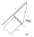
- FIG. 1 shows a first embodiment of a device according to the invention for drawing a material web into a rotary printing press.
- the device comprises a draw-in triangle 1, which is fastened to a track 3 and a guide device 2.
- the draw-in triangle 1 shown in the general view in FIG. 1 is fastened to the guide device 2 in such a way that it can be guided in the direction indicated by the arrow and forms a support for the web 3.
- a stiffening cap 4 provides additional support across the width of the web 3 and serves as a mounting interface between the web 3 and the draw-in triangle 1.
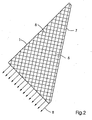
- Fig. 2 shows the orientation of the gain of the draw-in triangle 1, d. H. the substantially parallel to the hypotenuse 7 of the draw-in triangle 1 and the substantially orthogonal to the hypotenuse 7 of the draw-in triangle 1 extending reinforcing fibers of the mat material.
- the draw-in triangle 1 is made of a fabric mat. To distribute the tensile stress 8 caused by the web tension, the mat has a fiber direction 5 parallel to the hypotenuse 7 of the draw-in triangle 1 and a fiber direction 6 orthogonal to the hypotenuse 7 of the draw-in triangle 1.
- the mat is preferably made of a glass fiber-like material, for. B. carbon fiber reinforced plastic.
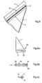
- Fig. 3a reinforcing and fastening arrangements of the draw-in triangle 1 are shown in more detail.
- the draw-in triangle 1 is connected to the material web. 3 connected via a stiffening attachment 4.
- the stiffening attachment 4 is connected by means of an adhesive and / or by sewing with the draw-in triangle 1, which is indicated by the seam 9.
- the web 3 is threaded through a gap 10 and glued to itself by means of preferably double-sided adhesive tape 11.
- the gap 10 is shown without threaded path.
- the gap 10 has an edge portion 12 made of a rounded material, which counteracts a severing of the web due to the thin material of the stiffening cap 4.
- FIG. 4 a shows a hook and loop arrangement 13 for fastening the draw-in triangle 1 to the guide device 2.
- the draw-in triangle 1 is fastened to the guide device 2 along the length of one side.
- an eyelet 14 is hooked into a hook 15.
- the hook 15 comprises a direction of transport of the material web 3 facing curved portion 16 through which the eyelet 14 is held on the hook 15 and prevents slipping of the draw-in triangle 1 of the guide means 2 when the Web is under tension when pulled.
- the shape of the hook 15 advantageously also allows easy removal of the draw-in triangle 1 after completion of the collection process.
- FIG. 5 shows a zipper arrangement according to the invention for fastening the draw-in triangle 1.
- the zipper 17 shown in this figure has the same function as the hook and eye assembly 13.
- the zipper 17 is attached to the guide device 2 and the draw-in triangle 1 with adhesive 18 and / or by sewing (seam 19).
- the position of the adhesive 18 and the seam 19 with respect to the zipper 17 can of course also be the reverse of the arrangement shown.
- both fixings can be made by adhesive or by sewing.
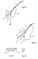
- FIG. 6a shows a fastening according to the invention of the draw-in triangle 1 on the track 3 by means of a clamping strip arrangement 20.
- the clamping strip arrangement 20 comprises two clamping bars 21, 22, between which the draw-in triangle 1 and the material web 3 are clamped.
- the clamping strips 21, 22 are clamped together, for example, by means of preferably countersunk or grooved screws 23 and / or clamps 24.
- the clamping bars 21, 22 preferably have a convex cross-section.
- Fig. 7a is a side view of the draw-in triangle 1 and the guide device 2.
- an external suspension device according to the invention is provided which allows fixing the draw-in triangle 1 on the guide device 2, without each eyelet 14 manually individually in the associated hook 15 must be hung.
- the suspension device comprises for fastening the draw-in triangle 1 on the guide device 2, a first guide portion 25 for the draw-in triangle 1 and a second guide portion 26 for the guide device 2.
- the first guide portion 25 the eyelets 14 in the manner relative to the hooks 15 that the end of the hook 15 can be passed through the eyelets 14.
- the guide device 2 is held during this process by the second guide 26 in its predetermined guide path.
- FIGS. 7c and 7d show how a hook 15 travels through a gap 27 formed in the first guide section 25 during the threading process. After hanging the eyelets 14 in the hooks 15, the draw-in triangle 1 and the guide means 2 are aligned parallel, so that the eyelet 14 is hooked on the hook 15. In this way, slippage of the draw-in triangle 1 is prevented by the guide device 2 during the web transport.
Landscapes
- Engineering & Computer Science (AREA)
- Mechanical Engineering (AREA)
- Replacement Of Web Rolls (AREA)
- Rotary Presses (AREA)
Claims (11)
- Dispositif d'insertion d'une bande de matériau (3) dans une presse rotative à imprimer, doté d'un triangle d'insertion (1) comprenant un premier côté d'une longueur prédéterminée, un côté inférieur et une hypoténuse, triangle sur lequel peut être fixée l'extrémité avant de la bande de matériau (3), et lequel est constitué d'un matériau en tissu, le matériau en tissu du triangle d'insertion (1) contenant des fibres de renforcement (5) s'étendant sensiblement parallèlement à l'hypoténuse (7), et le matériau en tissu contenant en plus des fibres de renforcement (6) s'étendant sensiblement perpendiculairement à l'hypoténuse (7), et doté d'un système de guidage (2),
caractérisé en ce que
le triangle d'insertion (1) est relié de manière amovible au système de guidage (2) sensiblement le long de toute la longueur prédéterminée du premier côté du triangle d'insertion (1). - Dispositif selon la revendication 1,
caractérisé en ce que
le premier côté du triangle d'insertion (1) peut être fixé en des points de fixation prédéterminés au système de guidage (2). - Dispositif selon l'une quelconque des revendications précédentes,
caractérisé en ce que
le triangle d'insertion (1) peut être fixé au système de guidage (2) au moyen de crochets (15) et d'oeillets (14). - Dispositif selon l'une quelconque des revendications 1 ou 2,
caractérisé en ce que
le triangle d'insertion (1) peut être fixé au système de guidage (2) au moyen d'une fermeture éclair (17). - Dispositif selon l'une quelconque des revendications précédentes,
caractérisé en ce que
le triangle d'insertion (1) est constitué d'un matériau similaire à une fibre de verre. - Dispositif selon l'une quelconque des revendications précédentes,
caractérisé en ce que
le triangle d'insertion (1) est constitué d'un matériau rugueux présentant un revêtement. - Dispositif selon l'une quelconque des revendications précédentes,
caractérisé en ce qu'
un chapeau de renforcement (4) flexible dans la direction de transport de la bande de matériau (3), par l'intermédiaire duquel la bande de matériau (3) peut être fixée au triangle d'insertion (1), est prévu sur le côté inférieur du triangle d'insertion (1). - Dispositif selon la revendication 7,
caractérisé en ce que
une fente (10) à travers laquelle l'extrémité avant de la bande de matériau (3) peut être guidée pour être fixée au triangle d'insertion (1) est formée sur le chapeau de renforcement (4). - Dispositif selon l'une quelconque des revendications 1 à 6,
caractérisé en ce que
la fixation de la bande de matériau (3) au triangle d'insertion (1) s'effectue au moyen d'un agencement de barrette de serrage (20). - Dispositif selon la revendication 3,
caractérisé en ce que
un dispositif d'accroche externe (13) est prévu, qui comporte une première section de guidage (25) destinée à accrocher les oeillets (14) et une seconde section de guidage (26) destinée à guider les crochets (15), et par l'intermédiaire duquel le système de guidage (2) est guidé de sorte que les oeillets (14) sont accrochés automatiquement dans les crochets (15). - Dispositif selon la revendication 10,
caractérisé en ce que
le dispositif d'accrochage externe (13) est disposé dans la zone du changeur de rouleau de la presse à imprimer.
Applications Claiming Priority (2)
| Application Number | Priority Date | Filing Date | Title |
|---|---|---|---|
| US09/335,368 US6223962B1 (en) | 1999-06-17 | 1999-06-17 | Method and apparatus for attaching a web of material for translation through a rotary printing press system |
| US335368 | 1999-06-17 |
Publications (4)
| Publication Number | Publication Date |
|---|---|
| EP1060880A2 EP1060880A2 (fr) | 2000-12-20 |
| EP1060880A3 EP1060880A3 (fr) | 2001-09-26 |
| EP1060880B1 EP1060880B1 (fr) | 2004-05-06 |
| EP1060880B2 true EP1060880B2 (fr) | 2007-05-09 |
Family
ID=23311486
Family Applications (1)
| Application Number | Title | Priority Date | Filing Date |
|---|---|---|---|
| EP00110200A Expired - Lifetime EP1060880B2 (fr) | 1999-06-17 | 2000-05-16 | Dispositif d'enfilage pour une machine rotative d'impression. |
Country Status (4)
| Country | Link |
|---|---|
| US (1) | US6223962B1 (fr) |
| EP (1) | EP1060880B2 (fr) |
| JP (1) | JP4638577B2 (fr) |
| DE (1) | DE50006303D1 (fr) |
Families Citing this family (11)
| Publication number | Priority date | Publication date | Assignee | Title |
|---|---|---|---|---|
| DE19837361A1 (de) | 1998-08-18 | 2000-02-24 | Koenig & Bauer Ag | Vorrichtung zum Einziehen einer Bedruckstoffbahn |
| DE10024010C1 (de) * | 2000-05-16 | 2001-09-20 | Koenig & Bauer Ag | Vorrichtung zum Einziehen einer Bahn |
| DE10106946A1 (de) | 2001-02-15 | 2002-08-22 | Heidelberger Druckmasch Ag | Einzugselement zum Einziehen einer Materialbahn |
| US6513428B1 (en) | 2001-07-23 | 2003-02-04 | Heidelberger Druckmaschinen Ag | Device and method for attaching a printing web to a webbing sail and device and method for webbing-up a printing machine |
| US6622959B2 (en) * | 2001-08-31 | 2003-09-23 | Martin Robitaille | Open clip automatic splicing system for hot melt coated tape rolls and method of using same |
| DE102005008984B3 (de) * | 2005-02-28 | 2006-08-03 | Koenig & Bauer Ag | Einziehvorrichtung für eine Bedruckstoffbahn in eine Druckmaschine |
| DE102007004755A1 (de) * | 2007-01-31 | 2008-08-07 | Man Roland Druckmaschinen Ag | Einziehspitze einer Vorrichtung zum Einziehen einer Bedruckstoffbahn in eine Druckmaschine |
| DE102007039486B4 (de) * | 2007-08-21 | 2011-08-25 | manroland AG, 63075 | Einziehen einer Bedruckstoffbahn in eine Rollenrotationsdruckmaschine |
| DE102007040969A1 (de) * | 2007-08-30 | 2009-03-05 | Manroland Ag | Einziehhilfe zm Einziehen einer Bedruckstoffbahn bzw. Teilbahn in eine Rollenrotationsdruckmaschine |
| AU2010283968B2 (en) * | 2009-08-21 | 2013-11-28 | Memjet Technology Limited | Continuous web printer with short media feed path |
| US8807474B2 (en) | 2011-03-04 | 2014-08-19 | Adalis Corporation | Tape splicing systems and methods |
Family Cites Families (16)
| Publication number | Priority date | Publication date | Assignee | Title |
|---|---|---|---|---|
| DE2212689A1 (de) * | 1972-03-16 | 1973-09-20 | Agfa Gevaert Ag | Vorrichtung zum behandeln eines bandfoermigen materials |
| US4330191A (en) * | 1981-02-17 | 1982-05-18 | Pako Corporation | Connector device for attaching photographic web material to a leader belt |
| US4480801A (en) * | 1982-05-13 | 1984-11-06 | Motter Printing Press Co. | Webbing system |
| DE3309121C1 (de) * | 1983-03-15 | 1984-08-16 | M.A.N.- Roland Druckmaschinen AG, 6050 Offenbach | Einrichtung zum Befestigen einer Materialbahn an dem Mitnehmer einer Bahneinzugsvorrichtung |
| DE3535852A1 (de) * | 1985-10-08 | 1987-04-16 | Agfa Gevaert Ag | Vorrichtung zum transportieren von bandfoermigem material, insbesondere fotopapier, durch eine behandlungsmaschine |
| DE3833469A1 (de) * | 1988-10-01 | 1990-04-05 | Agfa Gevaert Ag | Verfahren und vorrichtung zum befestigen des anfangs eines bandes von fotografischem material an einer klammer |
| DE3909470C1 (fr) | 1989-03-22 | 1990-03-22 | Man Roland Druckmaschinen Ag, 6050 Offenbach, De | |
| JPH07108741B2 (ja) * | 1989-04-04 | 1995-11-22 | 株式会社東京機械製作所 | 輪転機の紙通し装置 |
| EP0425741A1 (fr) * | 1989-11-01 | 1991-05-08 | Hamada Printing Press Co. Ltd. | Dispositif d'alimentation de bande pour rotative |
| JPH0757658B2 (ja) * | 1991-04-11 | 1995-06-21 | 株式会社東京機械製作所 | 紙通しにおける紙通し体とウェブ料紙との貼り合わせ方法及び貼り合わせ装置 |
| GB2256854B (en) * | 1991-06-18 | 1995-04-12 | Arthur Ronald Crouch | A leader for feeding strip material |
| DE9215764U1 (de) * | 1992-11-20 | 1993-01-14 | MAN Roland Druckmaschinen AG, 6050 Offenbach | Vorrichtung zum Einziehen einer Materialbahn mittels einer Einziehspitze |
| US5333771A (en) * | 1993-07-19 | 1994-08-02 | Advance Systems, Inc. | Web threader having an endless belt formed from a thin metal strip |
| DE19621507C1 (de) * | 1996-05-29 | 1997-09-18 | Heidelberger Druckmasch Ag | Bahneinzugsvorrichtung für eine bahnförmiges Material verarbeitende Maschine, insbesondere eine Rollenrotations-Druckmaschine |
| GB2314425B (en) * | 1996-06-20 | 2000-08-16 | Kodak Ltd | Photographic processing apparatus |
| GB2315062B (en) * | 1996-07-05 | 2000-12-13 | Gary Anthony Barrett | A leader for feeding paper web material |
-
1999
- 1999-06-17 US US09/335,368 patent/US6223962B1/en not_active Expired - Lifetime
-
2000
- 2000-05-16 EP EP00110200A patent/EP1060880B2/fr not_active Expired - Lifetime
- 2000-05-16 DE DE50006303T patent/DE50006303D1/de not_active Expired - Lifetime
- 2000-06-16 JP JP2000181827A patent/JP4638577B2/ja not_active Expired - Fee Related
Also Published As
| Publication number | Publication date |
|---|---|
| DE50006303D1 (de) | 2004-06-09 |
| JP4638577B2 (ja) | 2011-02-23 |
| JP2001030460A (ja) | 2001-02-06 |
| EP1060880B1 (fr) | 2004-05-06 |
| US6223962B1 (en) | 2001-05-01 |
| EP1060880A2 (fr) | 2000-12-20 |
| EP1060880A3 (fr) | 2001-09-26 |
Similar Documents
| Publication | Publication Date | Title |
|---|---|---|
| DE69015530T3 (de) | Papierbahneinführungsvorrichtung für Rotationsdruckmaschine. | |
| EP1060880B2 (fr) | Dispositif d'enfilage pour une machine rotative d'impression. | |
| DE202013012779U1 (de) | Energieabsorber | |
| EP0861040A1 (fr) | Rideau, notamment rideau a resserrer | |
| DE69916622T2 (de) | Spannvorrichtung | |
| DE10214140B4 (de) | Haltevorrichtung an den Transportketten einer Maschine zum Vorlegen von Fadengelegen, Verfahren zum Vorlegen und Fixieren von Filamentscharen zu einem Fadengelege und Multiaxialmaschine zur Durchführung des Verfahrens mit einer Haltevorrichtung | |
| DE60015171T2 (de) | Vorrichtung zur installation eines gewebes in einer papiermaschine | |
| DE102006005605A1 (de) | Vorrichtung an einer Karde für Baumwolle, Chemiefasern u. dgl., bei der mindestens ein Deckelstab mit einer Deckelgarnitur vorhanden ist. | |
| DE2619537A1 (de) | Endlosfiltergurt | |
| DE60013293T2 (de) | Vorrichtung zur installation eines gewebes in einer papiermaschine | |
| DE7235912U (de) | Vorrichtung zum herstellen eines harnischgliedes mit weblitze bzw. federanker und elastischer zugkordel bei einer jacquardmaschine | |
| DE3916740A1 (de) | Textilmaschine mit verstellbarer anpresswalzenanordnung | |
| DE69708979T2 (de) | Verfahren und Vorrichtung zum Aufwickeln einer Papierbahn | |
| DE2907540A1 (de) | Nehmergreifer fuer webmaschinen mit entnahme des schussfadens von ortsfesten spulen | |
| AT500335B1 (de) | Markise | |
| DE3001069C2 (fr) | ||
| DE2644505B2 (de) | Eintragnadel und Abziehnadel einer Webmaschine mit Übergabe des Schußfadens in der Mitte des Fachs | |
| DE112005003797T5 (de) | Verfahren und Vorrichtung zum Verbinden von Kordgewebe und Verbindungshalter in einer Kalanderanlage | |
| DE2623437A1 (de) | Nahtverbindung fuer breite und schwere gewebe | |
| DE3331634A1 (de) | Naehmaschine mit einer fuehrungskurvenanordnung fuer eine fadenfoerdereinrichtung | |
| DE1957452A1 (de) | Foerderband | |
| DE69211392T2 (de) | Mitnehmergreifer für schützenlose Webmaschinen, insbesondere zum Weben von synthetischen Fäden | |
| DE102024129031B3 (de) | Einfädelvorrichtung für eine Materialbahn | |
| DE10106946A1 (de) | Einzugselement zum Einziehen einer Materialbahn | |
| AT522716B1 (de) | Bandinstallationsvorrichtung |
Legal Events
| Date | Code | Title | Description |
|---|---|---|---|
| PUAI | Public reference made under article 153(3) epc to a published international application that has entered the european phase |
Free format text: ORIGINAL CODE: 0009012 |
|
| AK | Designated contracting states |
Kind code of ref document: A2 Designated state(s): AT BE CH CY DE DK ES FI FR GB GR IE IT LI LU MC NL PT SE Kind code of ref document: A2 Designated state(s): CH DE FR GB LI |
|
| AX | Request for extension of the european patent |
Free format text: AL;LT;LV;MK;RO;SI |
|
| PUAL | Search report despatched |
Free format text: ORIGINAL CODE: 0009013 |
|
| AK | Designated contracting states |
Kind code of ref document: A3 Designated state(s): AT BE CH CY DE DK ES FI FR GB GR IE IT LI LU MC NL PT SE |
|
| AX | Request for extension of the european patent |
Free format text: AL;LT;LV;MK;RO;SI |
|
| 17P | Request for examination filed |
Effective date: 20010905 |
|
| AKX | Designation fees paid |
Free format text: CH DE FR GB LI |
|
| 17Q | First examination report despatched |
Effective date: 20020528 |
|
| GRAP | Despatch of communication of intention to grant a patent |
Free format text: ORIGINAL CODE: EPIDOSNIGR1 |
|
| GRAS | Grant fee paid |
Free format text: ORIGINAL CODE: EPIDOSNIGR3 |
|
| GRAA | (expected) grant |
Free format text: ORIGINAL CODE: 0009210 |
|
| AK | Designated contracting states |
Kind code of ref document: B1 Designated state(s): CH DE FR GB LI |
|
| PG25 | Lapsed in a contracting state [announced via postgrant information from national office to epo] |
Ref country code: FR Free format text: LAPSE BECAUSE OF FAILURE TO SUBMIT A TRANSLATION OF THE DESCRIPTION OR TO PAY THE FEE WITHIN THE PRESCRIBED TIME-LIMIT Effective date: 20040506 Ref country code: GB Free format text: LAPSE BECAUSE OF FAILURE TO SUBMIT A TRANSLATION OF THE DESCRIPTION OR TO PAY THE FEE WITHIN THE PRESCRIBED TIME-LIMIT Effective date: 20040506 |
|
| REG | Reference to a national code |
Ref country code: GB Ref legal event code: FG4D Free format text: NOT ENGLISH |
|
| REG | Reference to a national code |
Ref country code: CH Ref legal event code: EP |
|
| REF | Corresponds to: |
Ref document number: 50006303 Country of ref document: DE Date of ref document: 20040609 Kind code of ref document: P |
|
| GBV | Gb: ep patent (uk) treated as always having been void in accordance with gb section 77(7)/1977 [no translation filed] |
Effective date: 20040506 |
|
| RAP2 | Party data changed (patent owner data changed or rights of a patent transferred) |
Owner name: GOSS INTERNATIONAL AMERICAS, INC. |
|
| PLAQ | Examination of admissibility of opposition: information related to despatch of communication + time limit deleted |
Free format text: ORIGINAL CODE: EPIDOSDOPE2 |
|
| PLBQ | Unpublished change to opponent data |
Free format text: ORIGINAL CODE: EPIDOS OPPO |
|
| PLBI | Opposition filed |
Free format text: ORIGINAL CODE: 0009260 |
|
| PLAQ | Examination of admissibility of opposition: information related to despatch of communication + time limit deleted |
Free format text: ORIGINAL CODE: EPIDOSDOPE2 |
|
| PLAR | Examination of admissibility of opposition: information related to receipt of reply deleted |
Free format text: ORIGINAL CODE: EPIDOSDOPE4 |
|
| PLBQ | Unpublished change to opponent data |
Free format text: ORIGINAL CODE: EPIDOS OPPO |
|
| PLAB | Opposition data, opponent's data or that of the opponent's representative modified |
Free format text: ORIGINAL CODE: 0009299OPPO |
|
| PLAX | Notice of opposition and request to file observation + time limit sent |
Free format text: ORIGINAL CODE: EPIDOSNOBS2 |
|
| 26 | Opposition filed |
Opponent name: MASCHINENFABRIK WIFAG Effective date: 20050204 |
|
| R26 | Opposition filed (corrected) |
Opponent name: MASCHINENFABRIK WIFAG Effective date: 20050204 |
|
| EN | Fr: translation not filed | ||
| REG | Reference to a national code |
Ref country code: CH Ref legal event code: NV Representative=s name: KIRKER & CIE SA |
|
| PLAF | Information modified related to communication of a notice of opposition and request to file observations + time limit |
Free format text: ORIGINAL CODE: EPIDOSCOBS2 |
|
| PLBB | Reply of patent proprietor to notice(s) of opposition received |
Free format text: ORIGINAL CODE: EPIDOSNOBS3 |
|
| PUAH | Patent maintained in amended form |
Free format text: ORIGINAL CODE: 0009272 |
|
| STAA | Information on the status of an ep patent application or granted ep patent |
Free format text: STATUS: PATENT MAINTAINED AS AMENDED |
|
| 27A | Patent maintained in amended form |
Effective date: 20070509 |
|
| AK | Designated contracting states |
Kind code of ref document: B2 Designated state(s): CH DE FR GB LI |
|
| REG | Reference to a national code |
Ref country code: CH Ref legal event code: AEN Free format text: AUFRECHTERHALTUNG DES PATENTES IN GEAENDERTER FORM |
|
| EN | Fr: translation not filed | ||
| PLAB | Opposition data, opponent's data or that of the opponent's representative modified |
Free format text: ORIGINAL CODE: 0009299OPPO |
|
| PGFP | Annual fee paid to national office [announced via postgrant information from national office to epo] |
Ref country code: CH Payment date: 20110525 Year of fee payment: 12 |
|
| REG | Reference to a national code |
Ref country code: CH Ref legal event code: PL |
|
| PG25 | Lapsed in a contracting state [announced via postgrant information from national office to epo] |
Ref country code: LI Free format text: LAPSE BECAUSE OF NON-PAYMENT OF DUE FEES Effective date: 20120531 Ref country code: CH Free format text: LAPSE BECAUSE OF NON-PAYMENT OF DUE FEES Effective date: 20120531 |
|
| PGFP | Annual fee paid to national office [announced via postgrant information from national office to epo] |
Ref country code: DE Payment date: 20130530 Year of fee payment: 14 |
|
| REG | Reference to a national code |
Ref country code: DE Ref legal event code: R119 Ref document number: 50006303 Country of ref document: DE |
|
| REG | Reference to a national code |
Ref country code: DE Ref legal event code: R119 Ref document number: 50006303 Country of ref document: DE Effective date: 20141202 |
|
| PG25 | Lapsed in a contracting state [announced via postgrant information from national office to epo] |
Ref country code: DE Free format text: LAPSE BECAUSE OF NON-PAYMENT OF DUE FEES Effective date: 20141202 |