EP1031532B1 - Stapler - Google Patents
Stapler Download PDFInfo
- Publication number
- EP1031532B1 EP1031532B1 EP00109306A EP00109306A EP1031532B1 EP 1031532 B1 EP1031532 B1 EP 1031532B1 EP 00109306 A EP00109306 A EP 00109306A EP 00109306 A EP00109306 A EP 00109306A EP 1031532 B1 EP1031532 B1 EP 1031532B1
- Authority
- EP
- European Patent Office
- Prior art keywords
- fork
- casing
- lift truck
- monomast
- envelope
- Prior art date
- Legal status (The legal status is an assumption and is not a legal conclusion. Google has not performed a legal analysis and makes no representation as to the accuracy of the status listed.)
- Expired - Lifetime
Links
Images


Classifications
-
- B—PERFORMING OPERATIONS; TRANSPORTING
- B66—HOISTING; LIFTING; HAULING
- B66F—HOISTING, LIFTING, HAULING OR PUSHING, NOT OTHERWISE PROVIDED FOR, e.g. DEVICES WHICH APPLY A LIFTING OR PUSHING FORCE DIRECTLY TO THE SURFACE OF A LOAD
- B66F9/00—Devices for lifting or lowering bulky or heavy goods for loading or unloading purposes
- B66F9/06—Devices for lifting or lowering bulky or heavy goods for loading or unloading purposes movable, with their loads, on wheels or the like, e.g. fork-lift trucks
- B66F9/075—Constructional features or details
- B66F9/07504—Accessories, e.g. for towing, charging, locking
-
- B—PERFORMING OPERATIONS; TRANSPORTING
- B66—HOISTING; LIFTING; HAULING
- B66F—HOISTING, LIFTING, HAULING OR PUSHING, NOT OTHERWISE PROVIDED FOR, e.g. DEVICES WHICH APPLY A LIFTING OR PUSHING FORCE DIRECTLY TO THE SURFACE OF A LOAD
- B66F9/00—Devices for lifting or lowering bulky or heavy goods for loading or unloading purposes
- B66F9/06—Devices for lifting or lowering bulky or heavy goods for loading or unloading purposes movable, with their loads, on wheels or the like, e.g. fork-lift trucks
- B66F9/075—Constructional features or details
- B66F9/07513—Details concerning the chassis
- B66F9/07531—Battery compartments
-
- B—PERFORMING OPERATIONS; TRANSPORTING
- B66—HOISTING; LIFTING; HAULING
- B66F—HOISTING, LIFTING, HAULING OR PUSHING, NOT OTHERWISE PROVIDED FOR, e.g. DEVICES WHICH APPLY A LIFTING OR PUSHING FORCE DIRECTLY TO THE SURFACE OF A LOAD
- B66F9/00—Devices for lifting or lowering bulky or heavy goods for loading or unloading purposes
- B66F9/06—Devices for lifting or lowering bulky or heavy goods for loading or unloading purposes movable, with their loads, on wheels or the like, e.g. fork-lift trucks
- B66F9/075—Constructional features or details
- B66F9/08—Masts; Guides; Chains
- B66F9/087—Monomasts
-
- B—PERFORMING OPERATIONS; TRANSPORTING
- B66—HOISTING; LIFTING; HAULING
- B66F—HOISTING, LIFTING, HAULING OR PUSHING, NOT OTHERWISE PROVIDED FOR, e.g. DEVICES WHICH APPLY A LIFTING OR PUSHING FORCE DIRECTLY TO THE SURFACE OF A LOAD
- B66F9/00—Devices for lifting or lowering bulky or heavy goods for loading or unloading purposes
- B66F9/06—Devices for lifting or lowering bulky or heavy goods for loading or unloading purposes movable, with their loads, on wheels or the like, e.g. fork-lift trucks
- B66F9/075—Constructional features or details
- B66F9/20—Means for actuating or controlling masts, platforms, or forks
Definitions
- the invention relates to a stacker according to claim 1.
- the drawbar is articulated on the drive part and actuates it directly Drive wheel over which a battery-operated electric motor is arranged. It is known to arrange drawbar and drive motor asymmetrically on one side.
- the lifting cylinder is part of a Lifting frame on which a load carriage is guided in a height-adjustable manner.
- the mast usually consists of two spaced mast sections, which are arranged in front of the drive part and on the with the drive part support connected radar arms.
- the lifting carriage points to opposite Sides of the guide rollers in the cross-sectionally U-shaped mast profiles are led.
- the lifting carriage forms a unit with the carrying tines of the load fork, which, except for the wheel arms, can be lowered to cover them.
- the load part consists of two forks and a so-called mono mast and a section on which the mast is supported.
- the mono mast raised along with the section supporting it and the wheel arms.
- the rear of the mast is arranged in a narrow housing that extends towards the rear beyond the section supporting the mast beyond the battery housing extends.
- the invention has for its object to provide a stacker that is agile, provides the operator with a good view and is user-friendly.
- the centrally arranged mast or mono mast is in the invention in that Housing of the chassis is integrated and protrudes only slightly beyond the outer contour.
- the protrusion only needs to be chosen so large that the load carriage does it Chassis not touched. This allows the monomast to be extremely effective and stable with to be connected to the chassis by the load carriage and in particular to absorb the load occurring moment.
- the cladding has a box profile.
- the panel prevents the operator reaches into the mast and can injure himself. She also gives the stacker with an appropriate optical design, an attractive appearance.
- the costume is preferably made of plastic material and can therefore be used in any Be shaped. You can by appropriate embossing or training represent different objects, making the mast as a Advertising space or advertising medium can be used.
- the panel is preferably detachably attachable, for example in the Lift mast to be clipped in. Therefore, depending on the user, a selected and for its advertising-serving disguise are used.
- the Cover one or more openings for receiving objects or from different functional uses.
- a is conceivable To accommodate the operating and / or display module in the paneling. With drawbar guided Forklift trucks are operated using actuators in the Tiller head. However, it is sometimes desirable to have additional displays and actuation functions accommodate that arranged in the panel in the invention could be.
- a functional insert can be provided in which Writing instruments and other parts required for the operator can be accommodated can. It is also conceivable to install a telephone device in the casing. It is also conceivable to place a radio or a cassette recorder in the casing to integrate or a coin operated device for rental purposes.
- the cladding can also be used for advertising purposes.
- the stacker according to Fign. 1 and 2 has a chassis 10 with a housing 12. An the rear of the chassis is in a housing 14 at one corner of the drive motor for the drive wheel, not shown, arranged below the engine.
- the battery to drive the motor is in the housing 12 and is not visible.
- the motor and drive wheel are seated on a bearing that is rotatable about a vertical axis Block (not recognizable), on which a drawbar 16 is articulated, the one drawbar head 18 has handles and functional elements for controlling the Motor and a lifting unit in the housing 12.
- a recess of the Housing 12 includes a so-called mono mast 20, which the mast for forms a load carriage 22.
- the monomast stands, as can be seen in particular from FIG. 2, only slightly over the outer contour laterally.
- the Monomast 20 consists of two cross-sectionally U-shaped mast profiles 24, 26, which between the Support arms 28, 30 or, the underlying, in Figs. 1 and 2 but not too recognizing radars are arranged.
- the mast profiles 24, 26 are so close together that there is still a clear space between the neighboring radar arms remains free.
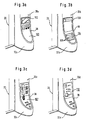
- the side of the mono mast 20 facing the drawbar 16 is through a box-like covering 30 covered, which extends downwards in the longitudinal plane widened, as indicated at 32. The broadening takes place in a gentle curve. Section 32 is rounded in the lower region. He's sitting on an approximately plan top 36 of the housing 12 of the chassis 10.
- the panel 30 is in not shown releasably connected to the monomast 20, for example clipped in and can be replaced by a different one.
- an opening 38 is formed which is rectangular in the upper area and rounded in the lower area (section 32). It receives an insert 40 with an upper compartment 42 which can be passed through bow-shaped section 4 is delimited and allows elongated objects can be inserted and held from above.
- a round receiving opening 46 is provided, for example for receiving a Bottle or the like. Smaller openings 48 on either side of the larger ones Opening 46 is used, for example, to hold writing utensils.
- the mono mast which is very narrow in the transverse direction, enables a good one Front view when the drawbar 16 is asymmetrical, i. H. arranged to one side is.
- the cladding 30 or 30a to 30f also with a Advertising printing can be provided or with a relief-like embossing or Formation through which z. B. certain objects are shown or hinted at be for the z. B. advertising is operated.
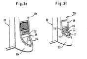
- FIG. 3 the lower region of the panel 30 according to Figures 1 and 2 for the Mast 20 shown in different designs.
- 3a is an insert 100 inserted into the opening 38 of the panel 30a, which as an additional display and operating module is used with corresponding actuation buttons and a display 102.
- a functional module 104 is in the opening 38 of the Cover 30b used, which can serve as a so-called write module with a device 106 for holding the block or the like and larger ones and smaller openings 108 for receiving writing utensils or the like.
- 3c shows a telephone, possibly a coin or card telephone, as a functional unit 107 inserted into the opening 38.
- a functional unit 110 is inserted into the opening 38, the so-called Pay and use unit serves.
- the stacker can be inserted by inserting a coin can be rented temporarily.
- a music function unit 112 is in the Opening 38 built in with radio, loudspeaker and recorder.
- 3f is a standard unit 113 inserted into the opening 114. It contains an ignition lock 115, one Display 117 and a drawer 119, for example an ashtray or the like.
- an opening 121 pointing upwards released to hold objects.
- the covering 30a to 30e for the mono mast 20 is always the same is executed, but accommodates different functional units.
- the user can therefore choose which functional unit when ordering the truck from the manufacturer he wishes.
Landscapes
- Engineering & Computer Science (AREA)
- Transportation (AREA)
- Structural Engineering (AREA)
- Civil Engineering (AREA)
- Life Sciences & Earth Sciences (AREA)
- Geology (AREA)
- Mechanical Engineering (AREA)
- Chemical & Material Sciences (AREA)
- Combustion & Propulsion (AREA)
- Forklifts And Lifting Vehicles (AREA)
- Handcart (AREA)
Description
- Fig. 1
- zeigt perspektivisch und schräg von hinten einen Stapler nach der Erfindung.
- Fig. 2
- zeigt perspektivisch den Stapler nach Fig. 1 schräg von vorn.
- Fign. 3a bis f
- zeigen perspektivisch verschiedene Ausführungen der Verkleidung des Hubmasts des Staplers nach Fign. 1 und 2.
Claims (5)
- Stapler für den Mitgehbetrieb miteinem ein Gehäuse (12) aufweisenden Antriebsteil (10),zwei am Antriebsteil (10) angebrachten Radarmen (28, 29),einem Hydraulikaggregat im Gehäuse (12),einem außermittig angeordneten Antriebsrad, das in einem Drehschemel des Antriebsteils (10) gelagert ist,einem auf dem Drehschemel angeordneten Elektromotor (14), der von einer im Gehäuse (12) angeordneten Batterie gespeist wird,einer am Drehschemel angelenkten außermittigen Deichsel (16) zur Lenkung des Staplers und Steuerung des Elektromotors (14) und des Hydraulikaggregats,einem mittig zwischen den Radarmen angeordneten Monomast (20), der zu den Radarmen (28, 29) einen wesentlichen Abstand hat und der in das Gehäuse (12) integriert ist und nur geringfügig über die Außenkontur des Gehäuses (12) vorsteht,einem an dem Monomast (20) geführten Lastteil mit Schlitten und Lastgabel, das von einem Hubzylinder im Monomast über eine Kette oder ein Seilzug verstellbar ist, wobei die Zinken (28, 29) der Lastgabel (22) zu den Radarmen ausgerichtet sind undeiner an der Rückseite angebrachten Verkleidung (30) für den Monomast (10) oberhalb des Gehäuses (12), die Kastenprofil aufweist und sich in der Längsebene nach unten allmählich verbreitert,wobei die Verkleidung (30) eine Öffnung (38) aufweist, die einen Gegenstand oder einen Funktionseinsatz (102, 110) aufnimmt.
- Stapler nach Anspruch 1, dadurch gekennzeichnet, daß die Verkleidung (30) lösbar anbringbar ist.
- Stapler nach Anspruch 1 oder 2, dadurch gekennzeichnet, daß die Verkleidung aus Kunststoffmaterial besteht.
- Stapler nach einem der Ansprüche 1 bis 3, dadurch gekennzeichnet, daß der Monomast (20) zwei im Querschnitt U-förmige, nahe zusammenliegende Mastprofile (24, 26) aufweist.
- Stapler nach einem der Ansprüche 1 bis 4, dadurch gekennzeichnet, daß der Elektromotor (14) in einer Ecke des Gehäuses (12) angeordnet ist.
Applications Claiming Priority (3)
| Application Number | Priority Date | Filing Date | Title |
|---|---|---|---|
| DE29514676U DE29514676U1 (de) | 1995-09-13 | 1995-09-13 | Stapler |
| DE29514676U | 1995-09-13 | ||
| EP96904091A EP0850190A1 (de) | 1995-09-13 | 1996-03-01 | Stapler |
Related Parent Applications (1)
| Application Number | Title | Priority Date | Filing Date |
|---|---|---|---|
| EP96904091A Division EP0850190A1 (de) | 1995-09-13 | 1996-03-01 | Stapler |
Publications (3)
| Publication Number | Publication Date |
|---|---|
| EP1031532A2 EP1031532A2 (de) | 2000-08-30 |
| EP1031532A3 EP1031532A3 (de) | 2000-09-13 |
| EP1031532B1 true EP1031532B1 (de) | 2002-01-30 |
Family
ID=8012949
Family Applications (2)
| Application Number | Title | Priority Date | Filing Date |
|---|---|---|---|
| EP00109306A Expired - Lifetime EP1031532B1 (de) | 1995-09-13 | 1996-03-01 | Stapler |
| EP96904091A Ceased EP0850190A1 (de) | 1995-09-13 | 1996-03-01 | Stapler |
Family Applications After (1)
| Application Number | Title | Priority Date | Filing Date |
|---|---|---|---|
| EP96904091A Ceased EP0850190A1 (de) | 1995-09-13 | 1996-03-01 | Stapler |
Country Status (7)
| Country | Link |
|---|---|
| US (1) | US6125971A (de) |
| EP (2) | EP1031532B1 (de) |
| AR (1) | AR001276A1 (de) |
| AU (1) | AU4831896A (de) |
| DE (2) | DE29514676U1 (de) |
| WO (1) | WO1997010170A1 (de) |
| ZA (1) | ZA961803B (de) |
Cited By (2)
| Publication number | Priority date | Publication date | Assignee | Title |
|---|---|---|---|---|
| DE10225080C1 (de) * | 2002-06-05 | 2003-12-04 | Yale Ind Products Gmbh | Flurförderfahrzeug |
| DE102010022341A1 (de) * | 2010-06-01 | 2011-12-01 | Jungheinrich Aktiengesellschaft | Griffelement für ein bewegliches Verkleidungsteil an einem Flurförderzeug |
Families Citing this family (39)
| Publication number | Priority date | Publication date | Assignee | Title |
|---|---|---|---|---|
| US6130101A (en) * | 1997-09-23 | 2000-10-10 | Molecular Probes, Inc. | Sulfonated xanthene derivatives |
| DE19756473C1 (de) * | 1997-12-18 | 1999-06-02 | Jungheinrich Ag | Hubwagen für Mitgeh- und Mitfahrbetrieb |
| ZA991297B (en) * | 1998-02-25 | 1999-08-20 | Inventio Ag | Elevator installation. |
| FR2775475B1 (fr) * | 1998-02-27 | 2000-04-21 | Loc Manutention | Mat de levage pour appareil de manutention du genre d'un chariot gerbeur |
| DE10002846B4 (de) * | 2000-01-24 | 2014-06-05 | Jungheinrich Aktiengesellschaft | Stapler |
| DE10006009C2 (de) * | 2000-02-11 | 2002-11-07 | Jungheinrich Ag | Flurförderzeug in Vierradausführung |
| DE10013063A1 (de) * | 2000-03-17 | 2001-09-20 | Still Gmbh | Informationsübermittlungssystem für eine mobile Arbeitsmaschine |
| DE10145991B4 (de) * | 2001-09-18 | 2021-02-11 | Linde Material Handling Gmbh | Rahmen für ein batteriebetriebenes Flurförderzeug |
| FR2838417B1 (fr) * | 2002-04-15 | 2004-10-22 | Loc Manutention | Chariot de manutention de charges |
| DE10221311B4 (de) * | 2002-05-14 | 2004-09-09 | Jungheinrich Ag | Niederhub-Flurförderzeug |
| US20030221914A1 (en) * | 2002-05-28 | 2003-12-04 | Smith Paul L. | Portable lift for rack mounting equipment |
| US7025157B2 (en) * | 2003-07-25 | 2006-04-11 | The Raymond Corporation | Pallet truck tiller arm with angle detector for speed select |
| US7810821B2 (en) * | 2005-06-28 | 2010-10-12 | Vestil Manufacturing Corp. | Storage device for use with a pallet jack |
| DE102006017889A1 (de) * | 2006-04-13 | 2007-10-25 | Linde Material Handling Gmbh | Flurförderzeug mit einer Batterie und Verfahren zum Betrieb eines Flurförderzeugs mit einer Batterie |
| DE102007004454A1 (de) * | 2007-01-30 | 2008-07-31 | Jungheinrich Ag | Anzeigeanordnung an einem Hochhubflurförderzeug |
| WO2010030803A1 (en) | 2008-09-12 | 2010-03-18 | Crown Equipment Corporation | Fork carriage apparatus for materials handling vehicle |
| DE202008013950U1 (de) * | 2008-10-18 | 2009-02-05 | Jungheinrich Ag | Flurförderzeug zum Transport von Sonderplatten |
| DE202009006960U1 (de) * | 2009-05-11 | 2009-08-20 | Jungheinrich Aktiengesellschaft | Flurförderzeug mit Verkleidung |
| DE102009056419B4 (de) * | 2009-12-01 | 2022-01-20 | Jungheinrich Aktiengesellschaft | Lastteil für ein Flurförderzeug |
| RU2012139461A (ru) * | 2010-02-17 | 2014-03-27 | Лифтер С.Р.Л. | Транспаллета |
| US8757326B2 (en) | 2011-10-12 | 2014-06-24 | Crown Equipment Corporaton | Pallet stops for lift trucks |
| CN102398877A (zh) * | 2011-11-21 | 2012-04-04 | 芜湖瑞创叉车有限公司 | 新型叉车 |
| CN102515056A (zh) | 2011-12-15 | 2012-06-27 | 浙江中力机械有限公司 | 搬运车 |
| US9586605B2 (en) | 2013-10-16 | 2017-03-07 | Big Lift, Llc | Powered pallet truck |
| USD739112S1 (en) | 2013-10-16 | 2015-09-15 | Big Lift, Llc | Powered pallet truck |
| US9475513B2 (en) * | 2014-07-25 | 2016-10-25 | Big Lift, Llc | Pallet truck |
| USD754415S1 (en) | 2014-10-15 | 2016-04-19 | Big Lift, Llc | Pallet truck |
| USD767236S1 (en) | 2015-02-05 | 2016-09-20 | Big Lift, Llc. | Pallet truck |
| US9522816B2 (en) * | 2015-05-05 | 2016-12-20 | Kenneth Taylor | Apparatus and method for moving catalyst bins |
| US9505595B1 (en) * | 2015-11-06 | 2016-11-29 | James Nelson Smith | Rapid delivery pallet jack system |
| US11046564B2 (en) * | 2015-11-09 | 2021-06-29 | Crown Equipment Corporation | Order picker materials handling vehicle with improved downward visibility when driving elevated |
| USD807609S1 (en) * | 2016-09-28 | 2018-01-09 | Crown Equipment Corporation | Power unit cover for an industrial vehicle |
| USD872965S1 (en) | 2018-04-17 | 2020-01-14 | Zhejiang E-P Equipment Co., Ltd. | Pallet truck |
| USD874083S1 (en) | 2018-04-18 | 2020-01-28 | Zhejiang E-P Equpiment Co., Ltd. | Pallet truck |
| USD891022S1 (en) | 2018-07-25 | 2020-07-21 | Zhejiang E-P Equipment Co., Ltd. | Powered Stacker Vehicle |
| USD933930S1 (en) * | 2019-04-24 | 2021-10-19 | Zhejiang Guozi Robotics Co., Ltd. | Transport robot |
| CN113636496B (zh) * | 2020-04-27 | 2023-06-16 | 林德(中国)叉车有限公司 | 一种紧凑型agv车架及agv叉车 |
| KR20230021008A (ko) | 2020-06-05 | 2023-02-13 | 크라운 이큅먼트 코포레이션 | 자재 취급 차량을 위한 조작자 제어 시스템 |
| USD975396S1 (en) | 2020-10-14 | 2023-01-10 | Zhejiang E-P Equipment Co., Ltd. | Pallet truck |
Family Cites Families (22)
| Publication number | Priority date | Publication date | Assignee | Title |
|---|---|---|---|---|
| US1029823A (en) * | 1911-06-24 | 1912-06-18 | Edwin C Richardson | Lifting implement. |
| US2395345A (en) * | 1942-09-10 | 1946-02-19 | Irvin F Schreck | Industrial truck |
| US2399632A (en) * | 1945-06-06 | 1946-05-07 | Towmotor Corp | Industrial truck |
| US2592091A (en) * | 1948-08-11 | 1952-04-08 | Towmotor Corp | Motorized hand truck |
| US2643740A (en) * | 1949-11-26 | 1953-06-30 | Yale & Towne Mfg Co | Lift truck |
| FR1056898A (fr) * | 1951-01-12 | 1954-03-03 | Perfectionnements aux chariots moteurs industriels | |
| US2785817A (en) * | 1953-11-20 | 1957-03-19 | Unit Mfg Company | Lifting mechanism attachment for lift trucks |
| US2840175A (en) * | 1956-02-09 | 1958-06-24 | Yale & Towne Mfg Co | Industrial truck handle operated control |
| US3068019A (en) * | 1959-11-05 | 1962-12-11 | Yale & Towne Mfg Co | Geometric steering for industrial truck |
| DE1174176B (de) * | 1959-11-26 | 1964-07-16 | Yale & Towne Inc | Hubwagen mit einer einen Motor und ein von diesem angetriebenes Antriebsrad aufweisenden Lenk- und Antriebseinheit |
| GB1026411A (en) * | 1962-05-07 | 1966-04-20 | Lansing Bagnall Ltd | Improvements in or relating to industrial trucks |
| US3187829A (en) * | 1963-01-29 | 1965-06-08 | Yale & Towne Inc | Brake and handle control for industrial truck |
| US3430374A (en) * | 1966-11-15 | 1969-03-04 | Robert Woodard | Emergency signal for automotive vehicles |
| US3756350A (en) * | 1971-03-01 | 1973-09-04 | Hyster Co | Materials handling truck |
| IT8236138V0 (it) * | 1982-11-18 | 1982-11-18 | Chimienti Miguel Julio | Telaio per avvisi pubblicitari su carrelli porta spese o porta pacchi |
| JPS59217597A (ja) * | 1983-05-23 | 1984-12-07 | 日産自動車株式会社 | フオ−クリフトトラツク用マストレ−ル構造 |
| DE3333166A1 (de) * | 1983-09-14 | 1985-03-28 | Walter 7290 Freudenstadt Finkbeiner | Hebebock |
| US4615533A (en) * | 1985-03-04 | 1986-10-07 | Sewell Daniel W | Method and apparatus for improved operation of pallet trucks |
| DE9005653U1 (de) * | 1990-05-18 | 1990-07-26 | Prasuhn, Andreas, 4952 Porta Westfalica, De | |
| US5097611A (en) * | 1990-07-10 | 1992-03-24 | Marchon, Inc. | Display apparatus |
| SE9002448L (sv) * | 1990-07-17 | 1992-01-18 | Ata Byy Markprod Ab | Vaegmaerkes- och informationstavleanordning |
| US5501297A (en) * | 1994-11-08 | 1996-03-26 | Harold Josephs | Safety guard assembly for fork lift trucks |
-
1995
- 1995-09-13 DE DE29514676U patent/DE29514676U1/de not_active Ceased
-
1996
- 1996-03-01 DE DE59608685T patent/DE59608685D1/de not_active Expired - Lifetime
- 1996-03-01 WO PCT/EP1996/000864 patent/WO1997010170A1/de not_active Application Discontinuation
- 1996-03-01 EP EP00109306A patent/EP1031532B1/de not_active Expired - Lifetime
- 1996-03-01 US US09/029,183 patent/US6125971A/en not_active Expired - Lifetime
- 1996-03-01 AU AU48318/96A patent/AU4831896A/en not_active Abandoned
- 1996-03-01 EP EP96904091A patent/EP0850190A1/de not_active Ceased
- 1996-03-05 ZA ZA961803A patent/ZA961803B/xx unknown
- 1996-03-19 AR AR33580396A patent/AR001276A1/es unknown
Cited By (2)
| Publication number | Priority date | Publication date | Assignee | Title |
|---|---|---|---|---|
| DE10225080C1 (de) * | 2002-06-05 | 2003-12-04 | Yale Ind Products Gmbh | Flurförderfahrzeug |
| DE102010022341A1 (de) * | 2010-06-01 | 2011-12-01 | Jungheinrich Aktiengesellschaft | Griffelement für ein bewegliches Verkleidungsteil an einem Flurförderzeug |
Also Published As
| Publication number | Publication date |
|---|---|
| WO1997010170A1 (de) | 1997-03-20 |
| ZA961803B (en) | 1996-09-10 |
| US6125971A (en) | 2000-10-03 |
| AR001276A1 (es) | 1997-10-08 |
| EP1031532A2 (de) | 2000-08-30 |
| AU4831896A (en) | 1997-04-01 |
| DE29514676U1 (de) | 1997-01-30 |
| EP0850190A1 (de) | 1998-07-01 |
| EP1031532A3 (de) | 2000-09-13 |
| DE59608685D1 (de) | 2002-03-14 |
Similar Documents
| Publication | Publication Date | Title |
|---|---|---|
| EP1031532B1 (de) | Stapler | |
| EP0949188B1 (de) | Kabine für ein Flurförderzeug | |
| DE60104358T2 (de) | Kraftfahrzeug mit einklappbarem Ablagemodul | |
| EP1394098B1 (de) | Schubmaststapler | |
| EP2036851A1 (de) | Mitfahrhubwagen | |
| EP1977989B1 (de) | Gabelhubwagen | |
| DE102011016841A1 (de) | Hochregalflurförderzeug, insbesondere Kommissionierflurförderzeug, mit einem Fahrersitz und seitlichen Armlehnen | |
| EP0652129B1 (de) | Kraftfahrzeug mit einem Fahrtschreiber | |
| EP3517401B1 (de) | Flurförderzeug | |
| EP1243490B1 (de) | Batterie-elektrisch betriebenes Flurförderzeug, insbesondere Gegengewichtsstapler | |
| EP0029880B1 (de) | Lastkraftwagen | |
| DE4222017C2 (de) | Bedieneinrichtung zur Ansteuerung von Motoren für das Absenken und Anheben von Seitenscheiben eines Kraftfahrzeuges | |
| EP0570658B1 (de) | Fahrerplatzrückwand für ein Kommissionierfahrzeug | |
| EP1398217B1 (de) | Deckel für ein Ablagefach in einem Fahrzeug | |
| DE19646039C2 (de) | Abdeckung des Motorraums eines verbrennungsmotorisch angetriebenen Stapelfahrzeugs | |
| DE20007793U1 (de) | Einrad-Rollstuhlgespann | |
| DE102005049098A1 (de) | Bedienpult mit modularem Aufbau für ein Flurförderzeug | |
| EP0633176B1 (de) | Transportsystem | |
| DE4219786C2 (de) | Fahrerplatz eines batteriebetriebenen Flurförderzeugs | |
| DE10258294B4 (de) | Batteriebetriebener Niederhubwagen | |
| EP1184220B1 (de) | Flurförderzeug | |
| DE102004024694B4 (de) | Karosserie für ein Fahrzeug | |
| EP1002760A1 (de) | Kabine für Frontsitz-Flurförderzeuge | |
| DE19934994B4 (de) | Elektromotorisch angetriebener Niederhubwagen | |
| EP0960850A2 (de) | Flurförderzeug, insbesondere Frontsitzgabelstapler |
Legal Events
| Date | Code | Title | Description |
|---|---|---|---|
| PUAI | Public reference made under article 153(3) epc to a published international application that has entered the european phase |
Free format text: ORIGINAL CODE: 0009012 |
|
| PUAL | Search report despatched |
Free format text: ORIGINAL CODE: 0009013 |
|
| 17P | Request for examination filed |
Effective date: 20000429 |
|
| AC | Divisional application: reference to earlier application |
Ref document number: 850190 Country of ref document: EP |
|
| AK | Designated contracting states |
Kind code of ref document: A2 Designated state(s): DE FR GB SE |
|
| AX | Request for extension of the european patent |
Free format text: AL;LT;LV;SI |
|
| AK | Designated contracting states |
Kind code of ref document: A3 Designated state(s): AT BE CH DE DK ES FI FR GB GR IE IT LI LU MC NL PT SE |
|
| AX | Request for extension of the european patent |
Free format text: AL;LT;LV;SI |
|
| AKX | Designation fees paid |
Free format text: DE FR GB SE |
|
| GRAG | Despatch of communication of intention to grant |
Free format text: ORIGINAL CODE: EPIDOS AGRA |
|
| GRAG | Despatch of communication of intention to grant |
Free format text: ORIGINAL CODE: EPIDOS AGRA |
|
| GRAH | Despatch of communication of intention to grant a patent |
Free format text: ORIGINAL CODE: EPIDOS IGRA |
|
| 17Q | First examination report despatched |
Effective date: 20010710 |
|
| GRAH | Despatch of communication of intention to grant a patent |
Free format text: ORIGINAL CODE: EPIDOS IGRA |
|
| GRAA | (expected) grant |
Free format text: ORIGINAL CODE: 0009210 |
|
| REG | Reference to a national code |
Ref country code: GB Ref legal event code: IF02 |
|
| AC | Divisional application: reference to earlier application |
Ref document number: 850190 Country of ref document: EP |
|
| AK | Designated contracting states |
Kind code of ref document: B1 Designated state(s): DE FR GB SE |
|
| PG25 | Lapsed in a contracting state [announced via postgrant information from national office to epo] |
Ref country code: GB Free format text: LAPSE BECAUSE OF FAILURE TO SUBMIT A TRANSLATION OF THE DESCRIPTION OR TO PAY THE FEE WITHIN THE PRESCRIBED TIME-LIMIT Effective date: 20020130 |
|
| REF | Corresponds to: |
Ref document number: 59608685 Country of ref document: DE Date of ref document: 20020314 |
|
| PG25 | Lapsed in a contracting state [announced via postgrant information from national office to epo] |
Ref country code: SE Free format text: LAPSE BECAUSE OF FAILURE TO SUBMIT A TRANSLATION OF THE DESCRIPTION OR TO PAY THE FEE WITHIN THE PRESCRIBED TIME-LIMIT Effective date: 20020430 |
|
| ET | Fr: translation filed | ||
| GBV | Gb: ep patent (uk) treated as always having been void in accordance with gb section 77(7)/1977 [no translation filed] |
Effective date: 20020130 |
|
| PLBE | No opposition filed within time limit |
Free format text: ORIGINAL CODE: 0009261 |
|
| STAA | Information on the status of an ep patent application or granted ep patent |
Free format text: STATUS: NO OPPOSITION FILED WITHIN TIME LIMIT |
|
| 26N | No opposition filed | ||
| REG | Reference to a national code |
Ref country code: FR Ref legal event code: PLFP Year of fee payment: 20 |
|
| PGFP | Annual fee paid to national office [announced via postgrant information from national office to epo] |
Ref country code: DE Payment date: 20150601 Year of fee payment: 20 |
|
| PGFP | Annual fee paid to national office [announced via postgrant information from national office to epo] |
Ref country code: FR Payment date: 20150331 Year of fee payment: 20 |
|
| REG | Reference to a national code |
Ref country code: DE Ref legal event code: R071 Ref document number: 59608685 Country of ref document: DE |