EP1028863B1 - Dichtungsverbindungselement, dichtungsendstück und dichtung - Google Patents
Dichtungsverbindungselement, dichtungsendstück und dichtung Download PDFInfo
- Publication number
- EP1028863B1 EP1028863B1 EP98955539A EP98955539A EP1028863B1 EP 1028863 B1 EP1028863 B1 EP 1028863B1 EP 98955539 A EP98955539 A EP 98955539A EP 98955539 A EP98955539 A EP 98955539A EP 1028863 B1 EP1028863 B1 EP 1028863B1
- Authority
- EP
- European Patent Office
- Prior art keywords
- sealing
- connecting element
- seal
- sealing profile
- profile
- Prior art date
- Legal status (The legal status is an assumption and is not a legal conclusion. Google has not performed a legal analysis and makes no representation as to the accuracy of the status listed.)
- Expired - Lifetime
Links
- 238000007789 sealing Methods 0.000 title claims abstract description 163
- 229920002725 thermoplastic elastomer Polymers 0.000 claims abstract description 11
- 238000003780 insertion Methods 0.000 claims description 6
- 230000037431 insertion Effects 0.000 claims description 6
- 238000013461 design Methods 0.000 claims description 5
- 238000004519 manufacturing process Methods 0.000 abstract description 9
- 238000001746 injection moulding Methods 0.000 abstract description 5
- 238000009434 installation Methods 0.000 abstract description 4
- 238000005520 cutting process Methods 0.000 abstract description 2
- 239000000463 material Substances 0.000 description 8
- 239000002184 metal Substances 0.000 description 8
- 229920001971 elastomer Polymers 0.000 description 5
- 239000000806 elastomer Substances 0.000 description 4
- 230000007704 transition Effects 0.000 description 4
- 230000007613 environmental effect Effects 0.000 description 3
- 238000004026 adhesive bonding Methods 0.000 description 2
- 230000000295 complement effect Effects 0.000 description 2
- 230000008878 coupling Effects 0.000 description 2
- 238000010168 coupling process Methods 0.000 description 2
- 238000005859 coupling reaction Methods 0.000 description 2
- 239000003292 glue Substances 0.000 description 2
- 238000002347 injection Methods 0.000 description 2
- 239000007924 injection Substances 0.000 description 2
- 210000001503 joint Anatomy 0.000 description 2
- 238000000034 method Methods 0.000 description 2
- 239000004952 Polyamide Substances 0.000 description 1
- 239000005062 Polybutadiene Substances 0.000 description 1
- -1 Polypropylene Polymers 0.000 description 1
- 239000004743 Polypropylene Substances 0.000 description 1
- 239000000853 adhesive Substances 0.000 description 1
- 230000001070 adhesive effect Effects 0.000 description 1
- 229920001400 block copolymer Polymers 0.000 description 1
- 210000000078 claw Anatomy 0.000 description 1
- 230000002860 competitive effect Effects 0.000 description 1
- 229920001577 copolymer Polymers 0.000 description 1
- 238000005260 corrosion Methods 0.000 description 1
- 230000007797 corrosion Effects 0.000 description 1
- 238000011161 development Methods 0.000 description 1
- 230000018109 developmental process Effects 0.000 description 1
- 238000005516 engineering process Methods 0.000 description 1
- 229920001821 foam rubber Polymers 0.000 description 1
- 239000000203 mixture Substances 0.000 description 1
- 238000000465 moulding Methods 0.000 description 1
- 229920002647 polyamide Polymers 0.000 description 1
- 229920002857 polybutadiene Polymers 0.000 description 1
- 229920000642 polymer Polymers 0.000 description 1
- 229920002959 polymer blend Polymers 0.000 description 1
- 229920001155 polypropylene Polymers 0.000 description 1
- 238000012545 processing Methods 0.000 description 1
- 230000005855 radiation Effects 0.000 description 1
- 238000000518 rheometry Methods 0.000 description 1
- 239000005060 rubber Substances 0.000 description 1
- 239000012945 sealing adhesive Substances 0.000 description 1
- 239000010865 sewage Substances 0.000 description 1
- 239000002904 solvent Substances 0.000 description 1
- 239000004753 textile Substances 0.000 description 1
- 229920001169 thermoplastic Polymers 0.000 description 1
- 239000004416 thermosoftening plastic Substances 0.000 description 1
- 238000003466 welding Methods 0.000 description 1
Images

Classifications
-
- B—PERFORMING OPERATIONS; TRANSPORTING
- B60—VEHICLES IN GENERAL
- B60J—WINDOWS, WINDSCREENS, NON-FIXED ROOFS, DOORS, OR SIMILAR DEVICES FOR VEHICLES; REMOVABLE EXTERNAL PROTECTIVE COVERINGS SPECIALLY ADAPTED FOR VEHICLES
- B60J10/00—Sealing arrangements
- B60J10/20—Sealing arrangements characterised by the shape
- B60J10/23—Sealing arrangements characterised by the shape assembled from two or more parts
- B60J10/233—Modular sealing arrangements, i.e. arrangements built up from a large number of joined modules
- B60J10/2335—Modular sealing arrangements, i.e. arrangements built up from a large number of joined modules with joint end members, e.g. abutting ends
-
- B—PERFORMING OPERATIONS; TRANSPORTING
- B60—VEHICLES IN GENERAL
- B60J—WINDOWS, WINDSCREENS, NON-FIXED ROOFS, DOORS, OR SIMILAR DEVICES FOR VEHICLES; REMOVABLE EXTERNAL PROTECTIVE COVERINGS SPECIALLY ADAPTED FOR VEHICLES
- B60J10/00—Sealing arrangements
- B60J10/20—Sealing arrangements characterised by the shape
- B60J10/21—Sealing arrangements characterised by the shape having corner parts or bends
-
- B—PERFORMING OPERATIONS; TRANSPORTING
- B60—VEHICLES IN GENERAL
- B60J—WINDOWS, WINDSCREENS, NON-FIXED ROOFS, DOORS, OR SIMILAR DEVICES FOR VEHICLES; REMOVABLE EXTERNAL PROTECTIVE COVERINGS SPECIALLY ADAPTED FOR VEHICLES
- B60J10/00—Sealing arrangements
- B60J10/20—Sealing arrangements characterised by the shape
- B60J10/23—Sealing arrangements characterised by the shape assembled from two or more parts
- B60J10/233—Modular sealing arrangements, i.e. arrangements built up from a large number of joined modules
-
- F—MECHANICAL ENGINEERING; LIGHTING; HEATING; WEAPONS; BLASTING
- F16—ENGINEERING ELEMENTS AND UNITS; GENERAL MEASURES FOR PRODUCING AND MAINTAINING EFFECTIVE FUNCTIONING OF MACHINES OR INSTALLATIONS; THERMAL INSULATION IN GENERAL
- F16B—DEVICES FOR FASTENING OR SECURING CONSTRUCTIONAL ELEMENTS OR MACHINE PARTS TOGETHER, e.g. NAILS, BOLTS, CIRCLIPS, CLAMPS, CLIPS OR WEDGES; JOINTS OR JOINTING
- F16B7/00—Connections of rods or tubes, e.g. of non-circular section, mutually, including resilient connections
- F16B7/04—Clamping or clipping connections
- F16B7/044—Clamping or clipping connections for rods or tubes being in angled relationship
-
- Y—GENERAL TAGGING OF NEW TECHNOLOGICAL DEVELOPMENTS; GENERAL TAGGING OF CROSS-SECTIONAL TECHNOLOGIES SPANNING OVER SEVERAL SECTIONS OF THE IPC; TECHNICAL SUBJECTS COVERED BY FORMER USPC CROSS-REFERENCE ART COLLECTIONS [XRACs] AND DIGESTS
- Y10—TECHNICAL SUBJECTS COVERED BY FORMER USPC
- Y10S—TECHNICAL SUBJECTS COVERED BY FORMER USPC CROSS-REFERENCE ART COLLECTIONS [XRACs] AND DIGESTS
- Y10S277/00—Seal for a joint or juncture
- Y10S277/921—Closure or weather strip seal
Definitions
- the invention relates to a seal connecting element, a seal end piece as well as a seal.
- Seals are used in many areas of daily life, to liquidate certain spaces from each other or towards the environment and / or gas-tight. A particularly important area of application the area of doors and flaps is suitable for seals which are regularly large due to assembly inaccuracies Sealing gaps occur.
- a special area of application for seals is automotive engineering, the regularly very high demands on the sealing behavior of a Seal and its resilience with regard to environmental influences such as temperature fluctuations, UV radiation, influence of solvents and other environmental factors.
- environmental influences such as temperature fluctuations, UV radiation, influence of solvents and other environmental factors.
- EPDM ethylene-propylene-diene copolymers
- NBR Natural Butadiene Rubber
- NR / SBR blends CR materials (Controlled Rheology Polypropylene materials).
- the sealing strand material represents because of its Flexibility in processing high demands on the Manufacturing process employed people.
- JP-A-22A 810/83 it is known per se to be butted Window sealing profiles through a locally formed sealing lip to seal against each other.
- DE-A-36 29 343 shows a corner connector as known per se tapered thorns, each with a cavity with a molding is attached and glued.
- an end cap is made in a manner known per se pushed onto an open end face of a clamping profile.
- the clamping profile was previously attached to a body flange.
- Figs. 1 and 5 it is known per se, to mount a bracket for a rearview mirror.
- the bracket has a partially coated with polymer Tail on.
- Connecting pins of adjacent frame profiles have one rectangular cross section and are in an open receiving channel introduced the corner piece.
- US-A-5 007 761 A shows the releasable connection as known per se a window shaft seal with a door seal for a coupé.
- On the window shaft seal is vulcanized onto a transition piece.
- the Transition piece has a recess into which an upper end of the Door seal can be inserted from below. In this inserted condition the connection is axially secured by a claw of the transition piece, which engages in a complementary recess of the door seal.
- the invention has for its object the manufacture of seals to facilitate.
- sealing connection elements and / or sealing end pieces as separate molded parts made of a thermoplastic Manufacture elastomer and these molded parts just before the installation of a seal with sealing profile strands to a complete Connect seal. Due to the separate production of the Sealing connection elements and / or sealing end pieces on the one hand or the sealing profile strands on the other hand and by their separate Transport facilitates the production of the individual parts and on the other hand minimized the transport effort. While according to the State of the art is required, sealing profile strands by hand for connection by means of an adhesive or a molded TPE corner piece to position it in an appropriate form, the Production of the sealing connection elements according to the invention and Carry out sealing end pieces fully automatically.
- these can be then assemble to complete gaskets in a kit, using sealing profile strands on the profile guide areas of the sealing connection elements or sealing end pieces are brought to the plant, whereby the assembly can be carried out particularly easily if longer sealing profile strands already attached to a rigid structure and are therefore fixed.
- thermoplastic elastomer becomes a Kit component provided, which allows the Installation of a seal on a structure that is not made to size to react quickly and easily in that instead of a sealing profile strand a different length of a different sealing profile strand with individually adjusted length is used. Thereby assembly costs and rejects are minimized.
- seals according to the invention and those used in them Sealing connecting elements or sealing end pieces underlying Kit concept is particularly advantageous when large-scale Seals or small series of seals are to be produced because then easier handling and the possibility to fall back pays off on standard parts.
- the profile guide area is preferably thin-walled, so that there is only a slight offset between the outer contour of the sealing profile strand and the outer contour of the seal connecting element occurs. This offset and a related leak. can be further reduced if the profile guide area against Is running out of zero.
- Sealing connecting element a holding section for clamping the Connecting element to a sealing profile strand to be connected having.
- glue or weld of the sealing connecting element with the respective sealing profile strand to renounce.
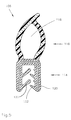
- the seal connecting element 100 shown in FIGS. 1 to 4 according to FIG a first embodiment is as a 90 ° corner piece for an engine compartment seal 124 provided. It is symmetrical to a miter plane formed and has a first insertion end 102 and a second insertion end 104 for receiving sealing profile strands 106.
- the sealing connection element has in the area of the insertion ends 102, 104 100 thin-walled profile guide areas 108, 110 on which the outer wall of an inserted sealing profile strand 106 so System come that between the sealing profile strand and sealing connecting element only a minimal level 112 remains, which is not noticeably affects the sealing behavior of the seal 124.
- the seal connector 100 is provided for a sealing profile strand 106 made of EPDM, which is shown in detail in FIG.
- This sealing profile strand 106 has a foot area 114 for fastening the sealing profile strand 106 on a metal web (not shown) and a sealing area 116 made of foam rubber with a Shore hardness of 15, which together with the foot region 114 forms a channel-like hollow chamber 118.
- In the foot area 114 is a cross section in a soft rubber (Shore hardness 60) U-shaped insert 120 made of metal included, which the Foot region 114 of the sealing profile strand 106 which is used to hold the metal web gives necessary rigidity.
- resilient lugs 122 are provided on the metal web.
- the seal connector 100 is designed so that it with his Outer contour follows the course of the sealing profile strand 106. Thereby becomes a metal web on which one of sealing profile strands 106 and seal connecting elements 100 existing seal 124 is plugged in, completely enclosed, causing corrosion of the Metal web can be prevented. Only in the push-on area of the The foot region 114 of the sealing profile strand 106 has the sealing connecting element 100 an opening, which is a jamming connection of sealing profile strand 106 and metal web allowed.
- Allow 100 and facilitate assembly is chamfered on the edge of the sealing connection element Core section 128 provided, its cross-sectional profile to the cross-sectional profile the hollow chamber 118 is adapted.
- the sealing connection element 100 has in the area of its first and second insertion end 102, 104 stops 130, 132 against which insertable sealing profile strands 106 can be pushed. If precisely pre-cut sealing profile tears 106 are used, can be extremely true to size taking these stops 130, 132 into account Make seals.
- the seal connector 100 is made of a thermoplastic Elastomer, preferably made of a polymer blend or a block copolymer and especially from TPE-V in a fully automated process injection molded.
- the mirror-symmetrical shape to the miter plane requires with injection molding only two cores, which move automatically to let go.
- the thermoplastic elastomer material used is adjusted so that a deformation of the sealing connecting element 100 in its sealing area 116 by at least 50% of its Extent of height is possible.
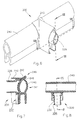
- the seal connecting element 200 shown in FIGS. 6 to 8 according to FIG a second embodiment instructs regarding the connection a first sealing profile strand on a design that matches the design of the seal connector 100 according to the first embodiment corresponds in the area of its insertion ends 102, 104.
- description of the seal connector 200 according to the second embodiment therefore become the description of areas, the areas of the seal connector 100 according to the first embodiment correspond, reference numerals used, which compared to the corresponding reference numerals increased by 100 in the first embodiment are. Reference is made to the corresponding description.
- the seal connector 200 is one for a butt joint first sealing profile strand (not shown) on a continuous second sealing profile strand 240 is provided.
- the continuous sealing profile strand 240 has the same features as the sealing profile strand 106.
- a seamless transition from the first Sealing profile strand to the second, continuous sealing profile strand To ensure 240, the profile guide area 210 of the Seal connector 200 to a holding portion 242 pulled through, which at its upper, at the sealing area 244 the end of the sealing extruded profile 240 has a hook 246, which is a sealing lug 248 of the second sealing profile strand 240 embraces.
- the holding portion 242 is shaped to be attached the outer contour of the second sealing profile strand 240 conforms.
- the seal connector 200 according to the second embodiment is like the seal connector 100 according to the first embodiment made of a thermoplastic elastomer by injection molding producible, whereby only two cores are required.
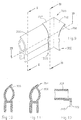
- seal connecting element 300 made of TPE according to one third embodiment shown.
- This gasket connector 300 is opposite to the sealing connection element 100 according to the first embodiment is a simplified embodiment, so that for sections, the sections of the seal connector 100 correspond to the first embodiment, reference numerals are used that were increased by 200. On the corresponding description is referred.
- the seal connector 300 consists essentially of two Holding sections 350, 352, which are shaped so that they abut one nestle the associated sealing profile strand 306.
- the two holding sections 350, 352 end in a common miter plane, the below 45 ° to the longitudinal extent of the holding sections 350, 352. she have at their upper ends a hook 354, 356 with which the sealing connector 300 on the sealing profile strands 306 holds.
- an abutment section for each holding section 350, 352 358, 360 is provided, which slides off the seal connecting element 300 prevented from the respective sealing profile strands.
- the sealing connecting element 300 is particularly simple to use Injection molding can be produced and requires only extremely little material. It has the disadvantage of being bluntly cut off Sealing profile strands at their ends both in the sealing area and also leaves open in the foot area.
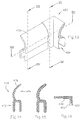
- a seal connecting element 400 is shown, which for sealing profile strands 470 according to a second embodiment is provided.
- These sealing profile strands 470 have one Foot area 472 on the design with a internal metal insert (not shown) and with retaining lugs (not shown) corresponds to the foot region 114 of the sealing profile strand 106, which is shown in Figs. 1 to 5.
- the sealing profile strand However, 470 does not have a chamber in its sealing region 474, but rather only one sealing lip 476. This sealing lip 476 and the Foot area 472 are defined by the seal connector 400 the fourth embodiment enclosed, only the plug-on area 426 remains free.
- the seal connector 400 according to the fourth Embodiment which like the other seal fasteners can be produced from a thermoplastic elastomer by injection molding is a particularly good compromise between material consumption and sealing behavior, whereby it should be emphasized that the entire foot area 472 of the sealing profile strands is completed, even if the sealing profile strands inexpensively transverse to their longitudinal extent be separated.
Landscapes
- Engineering & Computer Science (AREA)
- Mechanical Engineering (AREA)
- General Engineering & Computer Science (AREA)
- Gasket Seals (AREA)
- Seal Device For Vehicle (AREA)
- Connector Housings Or Holding Contact Members (AREA)
- Lining Or Joining Of Plastics Or The Like (AREA)
- Vehicle Waterproofing, Decoration, And Sanitation Devices (AREA)
- Building Environments (AREA)
Description
- Fig. 1
- eine erste Ausführungsform eines erfindungsgemäßen Dichtungsverbindungselements mit einem eingesteckten Dichtungsprofilstrang,
- Fig. 2
- einen Schnitt durch das Dichtungsverbindungselement in Fig. 1 gemäß der Linie II-II in Fig. 1,
- Fig. 3
- einen Schnitt durch das Dichtungsverbindungselement und den Dichtungsprofilstrang in Fig. 1 gemäß der Linie III-III in Fig. 1,
- Fig. 4
- einen Schnitt durch das Dichtungsverbindungselement und den Dichtungsprofilstrang in Fig. 1 gemäß der Linie IV-IV in Fig. 1,
- Fig. 5
- den Dichtungsprofilstrang in den Fig. 1 bis 4 in vergrößerter Darstellung,
- Fig. 6
- eine zweite Ausführungsform eines erfindungsgemäßen Dichtungsverbindungselements, welches seitlich an einen durchlaufenden Dichtungsprofilstrang angeklemmt ist,
- Fig. 7
- einen Schnitt durch das Dichtungsverbindungselement und den Dichtungsprofilstrang in Fig. 6 gemäß der Linie VII-VII in Fig. 6 und 8,
- Fig. 8
- einen Schnitt durch das Dichtungsverbindungselement und den Dichtungsprofilstrang in Fig. 6 gemäß der Linie VIII-VIII in Fig. 6,
- Fig. 9
- eine dritte Ausführungsform eines erfindungsgemäßen Dichtungsverbindungs elements mit einem Dichtungsprofilstrang,
- Fig. 10
- einen Schnitt durch den Dichtungsprofilstrang in Fig. 9 gemäß der Linie X-X in Fig. 9,
- Fig. 11
- einen Schnitt durch das Dichtungsverbindungselement und den Dichtungsprofilstrang in Fig. 9 gemäß der Linie XI-XI in Fig. 9,
- Fig. 12
- einen Schnitt durch das Dichtungsverbindungselement und den Dichtungsprofilstrang in Fig. 9 gemäß der Linie XII-XII in Fig. 9,
- Fig. 13
- eine vierte Ausführungsform eines erfindungsgemäßen Dichtungsverbindungselements mit einem Dichtungsprofilstrang,
- Fig. 14
- einen Schnitt durch den Dichtungsprofilstrang in Fig. 13 gemäß der Linie XIV-XIV in Fig. 13,
- Fig. 15
- einen Schnitt durch das Dichtungsverbindungselement und den Dichtungsprofilstrang in Fig. 13 gemäß der Linie XV-XV in Fig. 13, und
- Fig. 16
- einen Schnitt durch das Dichtungsverbindungselement und den Dichtungsprofilstrang in Fig. 13 gemäß der Linie XVI-XVI in Fig. 13.
Claims (12)
- Dichtungsverbindungselement (100;200;300;400) zur dichtenden Verbindung mindestens eines ersten und eines zweiten Dichtungsprofilstrangs (106;240;306;470) deren Enden nicht aneinander angeglichen sind, welches als Formteil mit einem Profilführungsbereich (108,110;210,242;310;410) aus einem thermoplastischen Elastomer getrennt von den Dichtungsprofilsträngen (106;240;306;470) geformt ist, wobei der Profilführungsbereich an einer Außenwand eines eingesteckten Dichtungsprofilstrangs zur Anlage kommt.
- Dichtungsverbindungselement nach Anspruchs 1, dadurch gekennzeichnet, daß der Profilführungsbereich dünnwandig, vorzugsweise gegen Null auslaufend ausgeführt ist.
- Dichtungsverbindungselement nach Anspruch 1 oder 2, gekennzeichnet durch mindestens einen Halteabschnitt (242;350,352) zum Anklemmen des Dichtungsverbindungselements an einen zu verbindenden Dichtungsprofilstrang (240;306).
- Dichtungsverbindungselement nach einem der Ansprüche 1 bis 3, gekennzeichnet durch mindestens einen ersten Anschlag (130,132; 232;332:432), der als Widerlager für einen mit dem Dichtungsverbindungselement steckend zu verbindenden Dichtungsprofilstrang (106;306;470) ausgebildet ist.
- Dichtungsverbindungselement nach einem der Ansprüche 1 bis 4, gekennzeichnet durch mindestens einen Kernabschnitt (128;228) zum Aufstecken einer Hohlkammer (118) eines Dichtungsprofilstrangs (106).
- Dichtungsverbindungselement nach einem der Ansprüche 1 bis 5, gekennzeichnet durch eine zu einer Gehrungsebene symmetrische Ausbildung Verbindung zweier gleicher Dichtungsprofilstränge.
- Dichtungsverbindungselement nach Anspruch 6, gekennzeichnet durch eine Gehrungsebene, die unter 15°, 30°, 45°, 60° oder 75° zur Einsteckrichtung der Dichtungsprofile verläuft.
- Dichtungsverbindungselement nach einem der Ansprüche 1 bis 5, gekennzeichnet durch einen Halteabschnitt (242) zur Befestigung eines Endes eines ersten Dichtungsprofilstrangs an einem durchlaufenden Dichtungsprofilstrang (240).
- Dichtungsendstück für Dichtungsprofilstränge, welches als Formteil mit einem Profilführungsbereich aus einem thermoplastischen Elastomer getrennt von den Dichtungsprofilsträngen geformt ist wobei der Profilführungsbereich an einer Außenwand eines eingesteckten Dichtungsprofilstrangs zur Anlage kommt.
- Dichtungsendstück nach Anspruch 9, gekennzeichnet durch eine Abschlußwand zum Verschluß einer Hohlkammer eines Dichtungsprofilstrangs.
- Dichtung mit mindestens einem Dichtungsprofilstrang (106;240;306;470) und einem Dichtungsverbindungselement (100;200;300;400) gemäß einem der Ansprüche 1 bis 8 und/oder einem Dichtungsendstück gemäß einem der Ansprüche 9 oder 10.
- Dichtung nach Anspruch 11, dadurch gekennzeichnet, daß der Dichtungsprofilstrang (106;240;306;470) und das Dichtungsverbindungselement bzw. das Dichtungseadstück zunächst lose gesteckt und dann miteinander verklebt oder verschweißt sind.
Applications Claiming Priority (3)
| Application Number | Priority Date | Filing Date | Title |
|---|---|---|---|
| DE29720053U DE29720053U1 (de) | 1997-11-12 | 1997-11-12 | Dichtungsverbindungselement, Dichtungsendstück und Dichtung |
| DE29720053U | 1997-11-12 | ||
| PCT/EP1998/007032 WO1999024279A1 (de) | 1997-11-12 | 1998-11-04 | Dichtungsverbindungselement, dichtungsendstück und dichtung |
Publications (2)
| Publication Number | Publication Date |
|---|---|
| EP1028863A1 EP1028863A1 (de) | 2000-08-23 |
| EP1028863B1 true EP1028863B1 (de) | 2001-10-17 |
Family
ID=8048505
Family Applications (1)
| Application Number | Title | Priority Date | Filing Date |
|---|---|---|---|
| EP98955539A Expired - Lifetime EP1028863B1 (de) | 1997-11-12 | 1998-11-04 | Dichtungsverbindungselement, dichtungsendstück und dichtung |
Country Status (8)
| Country | Link |
|---|---|
| US (2) | US6802666B1 (de) |
| EP (1) | EP1028863B1 (de) |
| JP (1) | JP2001522744A (de) |
| AT (1) | ATE207015T1 (de) |
| BR (1) | BR9814126A (de) |
| DE (2) | DE29720053U1 (de) |
| ES (1) | ES2162480T3 (de) |
| WO (1) | WO1999024279A1 (de) |
Families Citing this family (45)
| Publication number | Priority date | Publication date | Assignee | Title |
|---|---|---|---|---|
| DE20104747U1 (de) | 2001-03-20 | 2002-05-02 | Meteor Gummiwerke K. H. Bädje GmbH & Co, 31167 Bockenem | Spaltdichtungsanordnung |
| US20050242571A1 (en) * | 2002-12-06 | 2005-11-03 | Jon Houghton | Pipe fitting with composite gasket assembly |
| JP4251998B2 (ja) * | 2004-01-23 | 2009-04-08 | 豊田合成株式会社 | コンバーチブルカー用のルーフウエザストリップ |
| FR2874073B1 (fr) * | 2004-08-03 | 2006-11-24 | Hutchinson Sa | Dispositif de bouclage d'un joint d'etancheite |
| US20060091687A1 (en) * | 2004-10-29 | 2006-05-04 | Mantaline Corporation | Slide out sealing system |
| DE112006000797B4 (de) * | 2005-04-08 | 2019-04-18 | Lg Electronics Inc. | Dichtungskonstruktion für einen Kühlschrank |
| JP4330564B2 (ja) * | 2005-08-05 | 2009-09-16 | 豊田合成株式会社 | 自動車ドアのシール構造 |
| JP4788967B2 (ja) * | 2006-10-31 | 2011-10-05 | トヨタ紡織株式会社 | 車両用ドアトリム |
| US8458959B2 (en) * | 2007-03-30 | 2013-06-11 | Shiroki Corporation | Vehicle door frame structure |
| FR2915141A1 (fr) | 2007-04-18 | 2008-10-24 | Hutchinson Sa | Module d'etancheite pour baie de vehicule a moteur, et une telle baie l'incorporant. |
| US20090000231A1 (en) * | 2007-06-28 | 2009-01-01 | Burns Steven A | Sealing System for Suspended Ceilings |
| DE102008007244B4 (de) * | 2008-02-01 | 2010-12-23 | BSH Bosch und Siemens Hausgeräte GmbH | Kältegerät mit einem hohlprofilförmigen Dichtelement |
| DE202008010397U1 (de) * | 2008-08-05 | 2009-12-17 | Gebr. Bode Gmbh & Co. Kg | Eckverbindung Dichtungsprofile |
| EP2154058A1 (de) * | 2008-08-14 | 2010-02-17 | Spliethoff's Bevrachtingskantoor BV | Abdichtungsschott |
| DE102008061709A1 (de) * | 2008-12-12 | 2010-06-17 | Norsk Hydro Asa | Dichtungsprofil, Verbindungsvorrichtung und Dichtung |
| US10202796B2 (en) | 2009-10-05 | 2019-02-12 | R Value, Inc. | Press fit storm window system |
| US9580954B2 (en) | 2009-10-05 | 2017-02-28 | R Value, Inc. | Press fit storm window system |
| US9255438B2 (en) | 2009-10-05 | 2016-02-09 | R Value, Inc. | Press fit storm window system |
| US8272178B2 (en) * | 2009-10-05 | 2012-09-25 | R Value, Llc | Press-fit storm window |
| US20110078964A1 (en) * | 2009-10-05 | 2011-04-07 | R Value, Llc | Press-fit storm window system having controlled blowout |
| DE102009049455B4 (de) * | 2009-10-14 | 2013-07-18 | Draftex Automotive Gmbh | Dichtungsprofil und Verfahren zur Herstellung eines Dichtungsprofils |
| US20120007321A1 (en) * | 2010-07-07 | 2012-01-12 | Davis Marvin R | Sealing System |
| US8839564B2 (en) * | 2010-07-28 | 2014-09-23 | Press-Seal Gasket Corporation | Trailer door seal |
| JP5927208B2 (ja) * | 2011-02-25 | 2016-06-01 | シー イー エス コントロール エンクロージャー システムズ ゲーエムベーハー | 中空区画のためのシーリング要素及びシーリング・システム |
| DE102012209116A1 (de) * | 2012-05-30 | 2013-12-05 | Tesa Se | Heißsiegelbares Klebeband |
| US9032668B2 (en) | 2012-09-07 | 2015-05-19 | Press-Seal Gasket Corporation | Seal with primary and secondary sealing lobes for use in roll-up door applications |
| JP6268841B2 (ja) * | 2013-09-17 | 2018-01-31 | アイシン精機株式会社 | ルーフ装置 |
| US9151107B2 (en) | 2013-09-24 | 2015-10-06 | Press-Seal Gasket Corporation | Trailer door seal |
| PL3113966T3 (pl) | 2014-02-07 | 2019-11-29 | Henniges Automotive Sealing Systems North America Inc | Sposób wytwarzania zespołu uszczelniającego pojazdu |
| US10196912B2 (en) | 2014-10-24 | 2019-02-05 | United Technologies Corporation | Bifurcated sliding seal |
| DE102014016563A1 (de) * | 2014-11-08 | 2016-05-12 | GM Global Technology Operations LLC (n. d. Ges. d. Staates Delaware) | Kraftfahrzeugdichtung |
| JP6228166B2 (ja) * | 2015-07-03 | 2017-11-08 | 西川ゴム工業株式会社 | 自動車用ウェザーストリップ |
| US10088052B2 (en) * | 2015-09-22 | 2018-10-02 | Aktiebolaget Skf | Method of manufacturing a seal |
| US11155012B2 (en) | 2016-01-26 | 2021-10-26 | Henniges Automotive Sealing Systems North America, Inc. | Method of manufacturing a seal assembly for a vehicle |
| US9849757B2 (en) * | 2016-03-03 | 2017-12-26 | Dura Operating Llc | Extruded member corner connection |
| JP7033876B2 (ja) * | 2017-09-29 | 2022-03-11 | 極東開発工業株式会社 | 天蓋開閉装置付コンテナ |
| US10723050B2 (en) | 2017-11-29 | 2020-07-28 | Henniges Automotive Sealing Systems North America, Inc. | Method of manufacturing a window seal assembly with a molded bracket |
| WO2020018472A1 (en) | 2018-07-16 | 2020-01-23 | Moulton Wesley G | Gasket assembly |
| KR102621908B1 (ko) * | 2018-10-30 | 2024-01-05 | 현대자동차주식회사 | 후드 웨더스트립 어셈블리 |
| CN109733172B (zh) * | 2019-01-22 | 2024-04-09 | 衡阳泰豪通信车辆有限公司 | 一种双开盖式舱体的密封结构 |
| US11220166B2 (en) * | 2019-10-24 | 2022-01-11 | Nishikawa Rubber Co., Ltd. | Sealing member of sliding door |
| CN111775675A (zh) * | 2020-06-15 | 2020-10-16 | 中国第一汽车股份有限公司 | 一种汽车门洞密封条及其安装方法 |
| FR3121875B1 (fr) * | 2021-04-20 | 2023-03-03 | Psa Automobiles Sa | Dispositif de fixation d’un lecheur de vitre d’un vehicule notamment automobile |
| JP7471258B2 (ja) | 2021-06-25 | 2024-04-19 | 三菱電機株式会社 | 食器洗い機 |
| US12091152B2 (en) * | 2022-06-09 | 2024-09-17 | Embraer S.A. | Aircraft door seals and lap joint junction seal assemblies thereof |
Family Cites Families (34)
| Publication number | Priority date | Publication date | Assignee | Title |
|---|---|---|---|---|
| US2899720A (en) * | 1959-08-18 | Gasket | ||
| US1325804A (en) * | 1919-12-23 | Iffxchele w | ||
| US213577A (en) * | 1879-03-25 | Improvement in hose-couplings | ||
| US2784813A (en) * | 1955-07-07 | 1957-03-12 | Robert James Thompson | Frame construction |
| US3522359A (en) * | 1968-05-22 | 1970-07-28 | David Marshall | Earthing electrode |
| US3778175A (en) * | 1971-06-04 | 1973-12-11 | E Zimmer | Snap locking structural joint assembly |
| JPS58224810A (ja) | 1982-06-25 | 1983-12-27 | Nissan Motor Co Ltd | ドアサツシユのセンタ−サツシユ接続部のシ−ル構造 |
| US4447065A (en) * | 1983-02-28 | 1984-05-08 | The General Tire & Rubber Company | Sealing strip |
| JPS59195416A (ja) * | 1983-04-21 | 1984-11-06 | Kinugawa Rubber Ind Co Ltd | ウインドパネルモ−ルデイング |
| US4582987A (en) * | 1983-06-01 | 1986-04-15 | Bianco James S | Bar coded index tab holder |
| US4759555A (en) * | 1985-07-25 | 1988-07-26 | Eg&G Pressure Science, Inc. | Split ring seal with slip joint |
| GB2181698B (en) * | 1985-10-17 | 1990-01-24 | Draftex Ind Ltd | Reinforcing carriers for trimming and sealing strips and the like |
| JPH0624884B2 (ja) | 1985-12-28 | 1994-04-06 | 日産自動車株式会社 | 自動車用ウインドモ−ルのコ−ナ−モ−ル取付構造 |
| JPH0653458B2 (ja) * | 1986-07-30 | 1994-07-20 | 日産自動車株式会社 | 自動車用ウエザ−ストリツプ |
| DE3629343C2 (de) | 1986-08-28 | 1994-05-19 | Happich Gmbh Gebr | Scheibeneinfassung |
| JPH0698912B2 (ja) | 1988-01-18 | 1994-12-07 | 西川ゴム工業株式会社 | ソリツドスポンジメタルウエザーストリツプの接続方法 |
| DE3829968A1 (de) | 1988-09-03 | 1990-03-15 | Daimler Benz Ag | Dichtungsanordnung zum verbinden von dichtungen |
| CA1336444C (en) | 1989-01-12 | 1995-07-25 | Robert Albert Vaughan | Front loading flush glass run system |
| FR2642682B1 (fr) | 1989-01-16 | 1991-05-17 | Creusot Loire | Dispositif de support et de reglage de la position d'une entretoise superieure d'un moule de coulee sous pression de produits plats metalliques tels que des brames |
| US5085006A (en) * | 1989-04-24 | 1992-02-04 | Toyoda Gosei Co., Ltd. | Weather strip for motor vehicle |
| JPH07108643B2 (ja) | 1989-04-28 | 1995-11-22 | 鬼怒川ゴム工業株式会社 | ドリップチャンネル用ウエザーストリップ |
| JPH04185665A (ja) * | 1990-11-20 | 1992-07-02 | Nisshin Kagaku Kogyo Kk | ゴム組成物及びその硬化物 |
| IT1252066B (it) * | 1991-11-25 | 1995-05-29 | Ilpea Ind Spa | Guarnizione magnetica adatta ad effettuare una tenuta tra una parte fissa ed una parte apribile |
| US5271687A (en) * | 1992-04-03 | 1993-12-21 | Ford Motor Company | Space frame joint construction |
| US5297360A (en) * | 1992-08-20 | 1994-03-29 | General Electric Company | Refrigerator cabinet with combination sealing arrangement |
| DE4243043A1 (de) | 1992-12-18 | 1994-06-23 | Bayerische Motoren Werke Ag | Verfahren zum Verbinden von einander zugewandten Endabschnitten eines gummielastischen Dichtungsprofils |
| JP2919747B2 (ja) * | 1994-08-30 | 1999-07-19 | 鬼怒川ゴム工業株式会社 | シール部材用のスペーサ |
| US5566510A (en) * | 1994-10-26 | 1996-10-22 | Gencorp Inc. | Molded glass run channel corner assembly |
| US5575580A (en) * | 1995-05-03 | 1996-11-19 | Miracle Recreation Equipment Company | Connector for structural apparatus |
| JP3186551B2 (ja) * | 1995-11-06 | 2001-07-11 | 豊田合成株式会社 | ドアガラスランアウター |
| US5690446A (en) * | 1996-06-18 | 1997-11-25 | Somerville House Books Limited | Connection system for connecting struts to construct three-dimensional structures |
| DE19633627A1 (de) * | 1996-08-21 | 1998-02-26 | Dischler Helmut | Kupplungsvorrichtung für die Herstellung einer Rohrverbindung |
| US5785447A (en) * | 1996-11-21 | 1998-07-28 | Miracle Recreation Equipment Co. | Connector for structural apparatus |
| US6070364A (en) * | 1997-02-13 | 2000-06-06 | Schlegel Corporation | Flush glass seal insert with a belt-line extension |
-
1997
- 1997-11-12 DE DE29720053U patent/DE29720053U1/de not_active Expired - Lifetime
-
1998
- 1998-11-04 EP EP98955539A patent/EP1028863B1/de not_active Expired - Lifetime
- 1998-11-04 JP JP2000520321A patent/JP2001522744A/ja active Pending
- 1998-11-04 BR BR9814126-0A patent/BR9814126A/pt not_active IP Right Cessation
- 1998-11-04 AT AT98955539T patent/ATE207015T1/de not_active IP Right Cessation
- 1998-11-04 DE DE59801810T patent/DE59801810D1/de not_active Expired - Lifetime
- 1998-11-04 WO PCT/EP1998/007032 patent/WO1999024279A1/de active IP Right Grant
- 1998-11-04 ES ES98955539T patent/ES2162480T3/es not_active Expired - Lifetime
- 1998-11-04 US US09/554,402 patent/US6802666B1/en not_active Expired - Fee Related
-
2003
- 2003-03-19 US US10/391,963 patent/US6945540B2/en not_active Expired - Fee Related
Also Published As
| Publication number | Publication date |
|---|---|
| US6945540B2 (en) | 2005-09-20 |
| ES2162480T3 (es) | 2001-12-16 |
| BR9814126A (pt) | 2000-10-03 |
| DE29720053U1 (de) | 1999-03-18 |
| DE59801810D1 (de) | 2001-11-22 |
| JP2001522744A (ja) | 2001-11-20 |
| WO1999024279A1 (de) | 1999-05-20 |
| ATE207015T1 (de) | 2001-11-15 |
| US6802666B1 (en) | 2004-10-12 |
| US20030173748A1 (en) | 2003-09-18 |
| EP1028863A1 (de) | 2000-08-23 |
Similar Documents
| Publication | Publication Date | Title |
|---|---|---|
| EP1028863B1 (de) | Dichtungsverbindungselement, dichtungsendstück und dichtung | |
| DE3134340C2 (de) | Einklebbare Fahrzeug-Glasscheibe | |
| DE3929159C2 (de) | Dichtprofilleiste | |
| EP1370436A1 (de) | Dichtungsanordnung | |
| DD255764A5 (de) | Schellenband | |
| DE69931460T2 (de) | Fensterscheibe mit einem eine Spaltabdichtung umfassenden Profilstrang | |
| DE69101340T2 (de) | Gelenkverbindung zwischen einem Scheibenwischerarm und einem Scheibenwischerblatt. | |
| DE2434160A1 (de) | Ebenwandiger luftkanal oder dergleichen | |
| WO2018054661A1 (de) | Dichtungsanordnung für ein kraftfahrzeugfenster, dichtungsverbund und verfahren zum herstellen eines dichtungsverbundes | |
| DE3430649C2 (de) | ||
| EP0614775B1 (de) | Karosseriefenster | |
| DE3616661C2 (de) | ||
| DE29502439U1 (de) | Kombiniertes Blenden- und Türdichtungsteil zur Anbringung an einem Kraftfahzeug | |
| DE4307634A1 (de) | Karosseriefenster | |
| EP0546246B1 (de) | Kanalteilstück | |
| EP0155641A2 (de) | Vorrichtung zur Führung und Halterung einer beweglichen Fensterscheibe im Fensterrahmen eines Kraftfahrzeugs | |
| DE202013101492U1 (de) | Verbindungsanordnung für Fenster- oder Türprofile | |
| DE3125883C2 (de) | Gehrungseckverbindung für aus Kunststoff- oder kombinierten Metall-Kunststoff-Profilstäben zusammengesetzte Hohlprofil-Rahmen, insbesondere Fenster- oder Türrahmen | |
| DE10029544A1 (de) | Befestigungselement | |
| DE69403359T2 (de) | Ausrichteckwinkel für Metallfensterrahmen | |
| EP2107976A1 (de) | Dichtung zum abdichten der fensterscheibe eines kraftfahrzeugs, verstärkungsträger für eine solche dichtung und verfahren zum herstellen der dichtung | |
| EP3911530B1 (de) | Nutleiste und verfahren zur herstellung | |
| DE60000604T2 (de) | Endverschlusskappe für Rolladenkasten | |
| DE19750106C2 (de) | Eckstück für an einer Wand angebrachte Abdeckleisten | |
| EP2176084A1 (de) | Dichtungsanordnung |
Legal Events
| Date | Code | Title | Description |
|---|---|---|---|
| PUAI | Public reference made under article 153(3) epc to a published international application that has entered the european phase |
Free format text: ORIGINAL CODE: 0009012 |
|
| 17P | Request for examination filed |
Effective date: 20000118 |
|
| AK | Designated contracting states |
Kind code of ref document: A1 Designated state(s): AT BE CH DE DK ES FR GB IT LI NL SE |
|
| GRAG | Despatch of communication of intention to grant |
Free format text: ORIGINAL CODE: EPIDOS AGRA |
|
| 17Q | First examination report despatched |
Effective date: 20010710 |
|
| GRAG | Despatch of communication of intention to grant |
Free format text: ORIGINAL CODE: EPIDOS AGRA |
|
| GRAH | Despatch of communication of intention to grant a patent |
Free format text: ORIGINAL CODE: EPIDOS IGRA |
|
| GRAH | Despatch of communication of intention to grant a patent |
Free format text: ORIGINAL CODE: EPIDOS IGRA |
|
| GRAA | (expected) grant |
Free format text: ORIGINAL CODE: 0009210 |
|
| AK | Designated contracting states |
Kind code of ref document: B1 Designated state(s): AT BE CH DE DK ES FR GB IT LI NL SE |
|
| PG25 | Lapsed in a contracting state [announced via postgrant information from national office to epo] |
Ref country code: NL Free format text: LAPSE BECAUSE OF FAILURE TO SUBMIT A TRANSLATION OF THE DESCRIPTION OR TO PAY THE FEE WITHIN THE PRESCRIBED TIME-LIMIT Effective date: 20011017 |
|
| REF | Corresponds to: |
Ref document number: 207015 Country of ref document: AT Date of ref document: 20011115 Kind code of ref document: T |
|
| REG | Reference to a national code |
Ref country code: CH Ref legal event code: EP |
|
| PG25 | Lapsed in a contracting state [announced via postgrant information from national office to epo] |
Ref country code: AT Free format text: LAPSE BECAUSE OF NON-PAYMENT OF DUE FEES Effective date: 20011104 |
|
| GBT | Gb: translation of ep patent filed (gb section 77(6)(a)/1977) |
Effective date: 20011017 |
|
| REF | Corresponds to: |
Ref document number: 59801810 Country of ref document: DE Date of ref document: 20011122 |
|
| PG25 | Lapsed in a contracting state [announced via postgrant information from national office to epo] |
Ref country code: BE Free format text: LAPSE BECAUSE OF NON-PAYMENT OF DUE FEES Effective date: 20011130 |
|
| REG | Reference to a national code |
Ref country code: ES Ref legal event code: FG2A Ref document number: 2162480 Country of ref document: ES Kind code of ref document: T3 |
|
| REG | Reference to a national code |
Ref country code: GB Ref legal event code: IF02 |
|
| PG25 | Lapsed in a contracting state [announced via postgrant information from national office to epo] |
Ref country code: DK Free format text: LAPSE BECAUSE OF FAILURE TO SUBMIT A TRANSLATION OF THE DESCRIPTION OR TO PAY THE FEE WITHIN THE PRESCRIBED TIME-LIMIT Effective date: 20020117 |
|
| ET | Fr: translation filed | ||
| NLV1 | Nl: lapsed or annulled due to failure to fulfill the requirements of art. 29p and 29m of the patents act | ||
| BERE | Be: lapsed |
Owner name: METEOR GUMMIWERKE K.H. BADJE G.M.B.H. & CO. Effective date: 20011130 |
|
| PLBQ | Unpublished change to opponent data |
Free format text: ORIGINAL CODE: EPIDOS OPPO |
|
| PLBI | Opposition filed |
Free format text: ORIGINAL CODE: 0009260 |
|
| PLBF | Reply of patent proprietor to notice(s) of opposition |
Free format text: ORIGINAL CODE: EPIDOS OBSO |
|
| 26 | Opposition filed |
Opponent name: METZELER AUTOMOTIVE PROFILE SYSTEMS GMBH Effective date: 20020717 |
|
| PG25 | Lapsed in a contracting state [announced via postgrant information from national office to epo] |
Ref country code: LI Free format text: LAPSE BECAUSE OF NON-PAYMENT OF DUE FEES Effective date: 20021130 Ref country code: CH Free format text: LAPSE BECAUSE OF NON-PAYMENT OF DUE FEES Effective date: 20021130 |
|
| PLBF | Reply of patent proprietor to notice(s) of opposition |
Free format text: ORIGINAL CODE: EPIDOS OBSO |
|
| PLBF | Reply of patent proprietor to notice(s) of opposition |
Free format text: ORIGINAL CODE: EPIDOS OBSO |
|
| PLBF | Reply of patent proprietor to notice(s) of opposition |
Free format text: ORIGINAL CODE: EPIDOS OBSO |
|
| PLBP | Opposition withdrawn |
Free format text: ORIGINAL CODE: 0009264 |
|
| REG | Reference to a national code |
Ref country code: CH Ref legal event code: PL |
|
| PLBD | Termination of opposition procedure: decision despatched |
Free format text: ORIGINAL CODE: EPIDOSNOPC1 |
|
| PLBM | Termination of opposition procedure: date of legal effect published |
Free format text: ORIGINAL CODE: 0009276 |
|
| STAA | Information on the status of an ep patent application or granted ep patent |
Free format text: STATUS: OPPOSITION PROCEDURE CLOSED |
|
| 27C | Opposition proceedings terminated |
Effective date: 20030830 |
|
| PLAB | Opposition data, opponent's data or that of the opponent's representative modified |
Free format text: ORIGINAL CODE: 0009299OPPO |
|
| PGFP | Annual fee paid to national office [announced via postgrant information from national office to epo] |
Ref country code: SE Payment date: 20091120 Year of fee payment: 12 Ref country code: ES Payment date: 20091123 Year of fee payment: 12 |
|
| PGFP | Annual fee paid to national office [announced via postgrant information from national office to epo] |
Ref country code: IT Payment date: 20091127 Year of fee payment: 12 Ref country code: GB Payment date: 20091123 Year of fee payment: 12 Ref country code: FR Payment date: 20091202 Year of fee payment: 12 |
|
| PGFP | Annual fee paid to national office [announced via postgrant information from national office to epo] |
Ref country code: DE Payment date: 20101129 Year of fee payment: 13 |
|
| REG | Reference to a national code |
Ref country code: SE Ref legal event code: EUG |
|
| GBPC | Gb: european patent ceased through non-payment of renewal fee |
Effective date: 20101104 |
|
| REG | Reference to a national code |
Ref country code: FR Ref legal event code: ST Effective date: 20110801 |
|
| PG25 | Lapsed in a contracting state [announced via postgrant information from national office to epo] |
Ref country code: SE Free format text: LAPSE BECAUSE OF NON-PAYMENT OF DUE FEES Effective date: 20101105 |
|
| PG25 | Lapsed in a contracting state [announced via postgrant information from national office to epo] |
Ref country code: FR Free format text: LAPSE BECAUSE OF NON-PAYMENT OF DUE FEES Effective date: 20101130 |
|
| PG25 | Lapsed in a contracting state [announced via postgrant information from national office to epo] |
Ref country code: GB Free format text: LAPSE BECAUSE OF NON-PAYMENT OF DUE FEES Effective date: 20101104 |
|
| PG25 | Lapsed in a contracting state [announced via postgrant information from national office to epo] |
Ref country code: IT Free format text: LAPSE BECAUSE OF NON-PAYMENT OF DUE FEES Effective date: 20101104 |
|
| REG | Reference to a national code |
Ref country code: ES Ref legal event code: FD2A Effective date: 20120110 |
|
| PG25 | Lapsed in a contracting state [announced via postgrant information from national office to epo] |
Ref country code: ES Free format text: LAPSE BECAUSE OF NON-PAYMENT OF DUE FEES Effective date: 20101105 |
|
| REG | Reference to a national code |
Ref country code: DE Ref legal event code: R119 Ref document number: 59801810 Country of ref document: DE Effective date: 20120601 |
|
| REG | Reference to a national code |
Ref country code: DE Ref legal event code: R082 Ref document number: 59801810 Country of ref document: DE Representative=s name: CALLIES, RAINER, DIPL.-PHYS. DR.RER.NAT., DE Ref country code: DE Ref legal event code: R082 Ref document number: 59801810 Country of ref document: DE Representative=s name: RAINER CALLIES, DE |
|
| PG25 | Lapsed in a contracting state [announced via postgrant information from national office to epo] |
Ref country code: DE Free format text: LAPSE BECAUSE OF NON-PAYMENT OF DUE FEES Effective date: 20120601 |