US5690446A - Connection system for connecting struts to construct three-dimensional structures - Google Patents
Connection system for connecting struts to construct three-dimensional structures Download PDFInfo
- Publication number
- US5690446A US5690446A US08/664,916 US66491696A US5690446A US 5690446 A US5690446 A US 5690446A US 66491696 A US66491696 A US 66491696A US 5690446 A US5690446 A US 5690446A
- Authority
- US
- United States
- Prior art keywords
- receptor
- finger
- connection system
- tube
- connecting means
- Prior art date
- Legal status (The legal status is an assumption and is not a legal conclusion. Google has not performed a legal analysis and makes no representation as to the accuracy of the status listed.)
- Expired - Fee Related
Links
- 238000003780 insertion Methods 0.000 claims description 20
- 230000037431 insertion Effects 0.000 claims description 20
- 230000000295 complement effect Effects 0.000 claims description 14
- 230000007423 decrease Effects 0.000 claims description 2
- 238000010276 construction Methods 0.000 abstract description 2
- 239000000853 adhesive Substances 0.000 description 1
- 230000001070 adhesive effect Effects 0.000 description 1
- 238000005452 bending Methods 0.000 description 1
- 230000000694 effects Effects 0.000 description 1
- 239000000463 material Substances 0.000 description 1
- 238000000034 method Methods 0.000 description 1
- 238000012986 modification Methods 0.000 description 1
- 230000004048 modification Effects 0.000 description 1
Images


Classifications
-
- A—HUMAN NECESSITIES
- A63—SPORTS; GAMES; AMUSEMENTS
- A63H—TOYS, e.g. TOPS, DOLLS, HOOPS OR BUILDING BLOCKS
- A63H33/00—Other toys
- A63H33/04—Building blocks, strips, or similar building parts
- A63H33/10—Building blocks, strips, or similar building parts to be assembled by means of additional non-adhesive elements
- A63H33/101—Building blocks, strips, or similar building parts to be assembled by means of additional non-adhesive elements with clip or snap mechanism
-
- F—MECHANICAL ENGINEERING; LIGHTING; HEATING; WEAPONS; BLASTING
- F16—ENGINEERING ELEMENTS AND UNITS; GENERAL MEASURES FOR PRODUCING AND MAINTAINING EFFECTIVE FUNCTIONING OF MACHINES OR INSTALLATIONS; THERMAL INSULATION IN GENERAL
- F16B—DEVICES FOR FASTENING OR SECURING CONSTRUCTIONAL ELEMENTS OR MACHINE PARTS TOGETHER, e.g. NAILS, BOLTS, CIRCLIPS, CLAMPS, CLIPS OR WEDGES; JOINTS OR JOINTING
- F16B2200/00—Constructional details of connections not covered for in other groups of this subclass
- F16B2200/10—Details of socket shapes
-
- Y—GENERAL TAGGING OF NEW TECHNOLOGICAL DEVELOPMENTS; GENERAL TAGGING OF CROSS-SECTIONAL TECHNOLOGIES SPANNING OVER SEVERAL SECTIONS OF THE IPC; TECHNICAL SUBJECTS COVERED BY FORMER USPC CROSS-REFERENCE ART COLLECTIONS [XRACs] AND DIGESTS
- Y10—TECHNICAL SUBJECTS COVERED BY FORMER USPC
- Y10T—TECHNICAL SUBJECTS COVERED BY FORMER US CLASSIFICATION
- Y10T403/00—Joints and connections
- Y10T403/34—Branched
-
- Y—GENERAL TAGGING OF NEW TECHNOLOGICAL DEVELOPMENTS; GENERAL TAGGING OF CROSS-SECTIONAL TECHNOLOGIES SPANNING OVER SEVERAL SECTIONS OF THE IPC; TECHNICAL SUBJECTS COVERED BY FORMER USPC CROSS-REFERENCE ART COLLECTIONS [XRACs] AND DIGESTS
- Y10—TECHNICAL SUBJECTS COVERED BY FORMER USPC
- Y10T—TECHNICAL SUBJECTS COVERED BY FORMER US CLASSIFICATION
- Y10T403/00—Joints and connections
- Y10T403/44—Three or more members connected at single locus
Definitions
- This invention relates to connection system for connecting struts to construct three-dimensional structures.
- connection systems for connecting struts to construct three-dimensional useful structures, such as furniture, toys and buildings are numerous in the prior art.
- Such a system for example, is shown in Gabriel U.S. Pat. No. 4,129,975.
- the prior art connection systems utilize struts which are custom manufactured to cooperate with the connection systems.
- the struts utilized have snap fit clip ends.
- the struts utilized have joint ends and flanges.
- the connection systems of the prior art require the user to purchase such custom manufactured struts. Due to the design of the connection systems, the user cannot readily construct his own struts. As a result, the user's ability to construct various structures is constrained by the pre-determined length of the custom-manufactured struts.
- connection system which connects struts which do not have to be custom manufactured, but which can be readily constructed by the user of the connection system from an abundant, relatively inexpensive recyclable material such as newspaper.
- paper such as newspaper is generally readily available in sufficient quantity, it would be helpful to have a connection system which connects struts constructed from re-used paper, such as newspaper.
- connection system of the present invention is for connecting tubular struts to form a three-dimensional framework.
- Each strut is formed from at least one paper sheet rolled into a tube having a predetermined outside and inside diameter.
- connection system comprises a plurality of cylindrical receptors, each having an end for receiving one end of a tubular strut or tube and a connector for connecting at least two receptors to the connector.
- a finger projects from the interior of the cylindrical receptor such that when one end of a strut or tube is inserted into the receptor, the finger matingly projects into the inside of the tube.
- the outside and inside diameters of the tube are such that its end friction fits into the open end of the receptor and does not slip out from it.
- a connector is connected to a receptor by press fit engagement of connecting means on the receptor with complementary connecting means on the connector.
- the complementary connecting means on the connector is an opening and the connecting means on the receptor is an extension.
- the connector is generally cubic and has an opening in the centre of each of its faces.
- connection system for connecting struts formed from paper or paper-like sheets rolled into a tubular strut or tube comprising (i) a plurality of cylindrical receptors each having an inside diameter approximately equal to or slightly smaller than the predetermined outside diameter of the tubes for friction-fit engagement onto the ends of each tube and in which the receptors also have separate connecting means on each receptor for press-fit detachable engagement of each receptor with a complementary connecting means on a connector and (ii) a plurality of connectors wherein each connector has at least two such complementary connecting means for connecting at least two receptors to the connector and by this to each other.
- the invention comprises a receptor for a rolled paper tube comprising a cylinder of an inside diameter approximately equal to or slightly smaller than the predetermined outside diameter of a rolled paper tube to be inserted into the cylinder at one end and a finger within the cylinder and centrally disposed about the longitudinal axis of the cylinder, formed from a plurality of longitudinal ribs and defining between the outside surface of the finger and the inside surface of the cylinder an annular channel for receiving the paper tube and in which a part of the finger is substantially located at the inside diameter of the tube and means on the cylinder for connection to another receptor for a rolled paper tube.
- FIG. 1 is a pictorial view showing a framework formed using the connection system of the present invention and struts formed at least one paper sheet rolled into a tube;
- FIG. 2 is a perspective view of the connection system and an end of the tube
- FIG. 3 is a perspective view of the connector of the present connection system
- FIG. 4 is a perspective view of one embodiment of the receptor of the present connection system
- FIG. 5 is a side elevational view of a second embodiment of the receptor of the present connection system
- FIG. 6 is a front elevational view of a third embodiment of the receptor of the present connection system.
- FIG. 7 is a side elevational view of the receptor shown in FIG. 6;
- FIG. 8 is a perspective unassembled view of the receptor shown in FIG. 6;
- FIG. 9 is a rear perspective unassembled view of the second embodiment of the receptor shown in FIG. 5;
- FIG. 10 shown on the same page as FIG. 8, is a sectional view of the receptor of FIG. 4 taken along line 10--10;
- FIG. 11 is a plan view of the open end of the receptor of FIG. 4;
- FIG. 12 is a perspective view of a tube with strut rings slipped over each end;
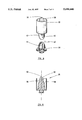
- FIG. 13 is a partial fragmentary perspective view of a receptor and a tube
- FIG. 14 is a fully assembled elevational view of the receptor and tube of FIG. 13.
- connection system of the present invention is for connecting tubular struts 20 to form a framework.
- Each strut 20 is comprised of at least one paper sheet rolled into a tube 22, having a predetermined outside and inside diameter.
- connection system comprises a plurality of connectors 24 and a plurality of cylindrical receptors 26.
- One such connector 24 and one such receptor 26 are best illustrated in FIG. 2.
- Receptor 26 has an open end 28 and an insertion end 30. Open end 28 has an inside diameter approximately equal to or slightly smaller than the predetermined outside diameter of tube 22 for friction-fit engagement onto the end of tube.
- Connector 24 connects at least two receptors 26 to it at their insertion ends 30.
- connector 24 connects to receptors 26 by press-fit detachable engagement of a separate connecting means on each receptor with a complementary connecting means on the connector.
- Each connector 24 has at least two such complementary connecting means for connecting at least two receptors 26 to the connector 24.
- the connecting means on the receptor is an extension 50 (FIGS. 4 and 5), while the complementary connecting means on the connector is an opening 32 (FIG. 3).
- the receptor 26 has an extension 50 for insertion into connector 24, the extension 50 could be on the connector 24 for insertion into the receptor 26.
- any secure detachable method can be used for connecting connector 24 with receptors 26 which could include, for instance, velcro, screws, bolts or pins.
- each connector 24 is hollow and generally cubic in shape.
- the connector 24 need not be cubic, but may be of any shape provided that the connector preferably has at least three complementary connecting means in which a second complementary connecting means is approximately 90 degrees from a first complementary connecting means and in which a third complementary connecting means is approximately 180 degrees from the first complementary connecting means, thereby permitting the receptors to be joined at 90 degree or 180 degree angles with respect to one another.
- the connector 24 could be a ball, an octagon, a pyramid or any convenient multi-sided shape. For some multi-sided shapes, openings could be placed at 45 degree angles so as to avoid the use of the second variant shown in FIG. 5.
- each receptor 26 comprises an open end 28 circumscribing a central axis AA i , and an insertion end 30 circumscribing a central axis BB i , wherein central axis BB i is coincident with central axis AA i .
- each receptor 26 comprises an open end 28 circumscribing a central axis CC i , and an insertion end 30 circumscribing a central axis DD i , wherein central axis DD i is oriented at a 45 degree angle with respect to central axis CC i .
- each receptor comprises an open end 28, an insertion end 30, and intermediate hinging means 38 for hingedly connecting the open end 28 to the insertion end 30.
- the hinging means 38 comprises a knuckle joint in which the insertion end 30 has a pair of side leaves 40 projecting therefrom and the open end 28 has a center leaf 42 extending therefrom to slide between the pair of side leaves 40.
- Each leaf 40 has an eye through which a pin 48 is inserted to retain the center leaf 42 in place between the side leaves 40.
- the hinging means 38 need not comprise a knuckle hinge, but may be of any construction, provided that the hinging means 38 permits the open end 28 to swing up to 180 degrees about the axis of rotation of the hinging means 38.
- the insertion end 30 has the pair of side leaves 40 and open end 28 has the center leaf 42, in an equally preferred embodiment, the center leaf 42 could be on the insertion end 30 and the side leaves 40 could be on the open end 28.
- extension 50 projects from the insertion end 30 of the receptor away from the open end 28.
- the extension 50 is centrally disposed on the insertion end 30.
- Extension 50 being circular in cross-section in the preferred embodiment, is adapted for insertion into the circular opening 32 on the connector 24 (FIG. 3).
- extension 50 has a flange 52 circumscribing its free end 54 for interlocking with a connector 24 once extension 50 is fully inserted and seated in the opening 32 on a connector 24.
- flange 52 resembles a battlement.
- Opening 32 has a diameter slightly greater than the diameter of extension 50, but slightly smaller than the diameter of extension 50 at flange 52.
- Flange 52 is slightly compressible.
- extension 50 when extension 50 is urged against opening 32, flange 52 is deflected slightly inwardly, such that the diameter of opening 32 in this compressed position is slightly greater than the diameter of extension 50 at flange 52.
- Bevelled edge 36 (FIG. 3) of opening 32 facilitates such insertion.
- receptor 26 is adapted to receive one end of a strut 20 such that the strut 20 is at an angle perpendicular to the face 34 (FIG. 3) in the connector 24 having opening 32 in which extension 50 (not shown) of receptor 26 is inserted.
- receptor 26 is adapted to receive one end of a strut 20 (not shown) such that strut 20 is at a 45 degree angle with the face 34 in the connector 24 (not shown) having opening 32 in which extension 50 of receptor 26 is inserted.
- FIGS in the third variant of receptor 26 shown in FIGS.
- receptor 26 is adapted to receive one end of a strut 20 such that the strut 20 can be positioned at an angle between 0 and 180 degrees with respect to the face 34 in the connector 24 having opening 32 in which extension 50 of receptor 26 is inserted.
- finger 56 projects from the insertion end 30 of receptor 26 into and beyond the open end 28 of receptor 26.
- Finger 56 is made of a plurality of longitudinal ribs 58 extending radially from the longitudinal axis of finger 56. Finger 56 is symmetric about its longitudinal axis. The radius of each rib 58 decreases as the distance to the insertion end 30 of receptor 26 increases.
- each rib 58 is reduced radially so that it curves inwardly.
- each rib 58 has the side profile of half a bell, as is best illustrated in FIG. 10.
- ribs 58 taper to form a finger tip 62.
- Finger 56 is star-shaped in plan, FIG. 11. The outside surface of finger 56 and the inside surface of the receptor 26 define an annular channel for receiving the tube 22.
- strut 20 comprises a tube 22 formed of at least one paper sheet rolled into a tube 22, having a predetermined outside and inside diameter.
- tube 22 is formed of a plurality of paper sheets 64 (not shown). Paper sheets 64 of equal size are stacked neatly, one on top of the other, such that each sheet is lined up evenly with the sheet below. The paper sheets 64 are rolled to form a tightly rolled tube 22. Strut rings 66 having an inside diameter corresponding to the inside diameter of open end 28 of receptor 26 are slipped over each end of tube 22, FIG. 12. Tube 22 unrolls by itself to fit snugly to the inside diameter of the rings 66, such that tube 22 is hollow.
- Tube 22 is fastened with fastening means, for example with tape or another adhesive, so that it does not unroll and such that the diameter of tube 22 maintains the same diameter as rings 66. Strut rings 66 are then removed from tube 22.
- strut 20 or tube 22 is attached to a receptor 26 by fully inserting one end of tube 22 into open end 28 of receptor 26 so that finger 56 is substantially located at the inside diameter of the tube 22.
- Tube 22 is fully inserted into open end 28 of receptor 26 when tube 22 can be seen through hole 68 as shown in FIG. 14. Hole 68 is located in the side of the receptor 26, near the insertion end 30.
- tube 22 friction fits snugly into open end 28 of receptor 26, such that tube 22 does not slip out from receptor 26.
- tube 22 is wedged between finger 56 and the inside surface of the receptor 26.
- Receptor 26 is attached to connector 24 by forcing extension 50 into opening 32 of connector 24 as described above.
Abstract
A connection system for connecting struts formed from paper or paper-like sheets rolled into a tube is made of cylindrical receptors and connectors. Each cylindrical receptor has an inside diameter approximately equal to or slightly smaller than the predetermined outside diameter of the tube for friction-fit engagement onto the end of the tube. Each cylindrical receptor also has a finger which is centrally disposed within the receptor, about the longitudinal axis thereof. At least a part of such finger is substantially the same size as the inside diameter of the tube. The finger is made of a plurality of longitudinal ribs extending radially from its longitudinal axis. Each receptor is press-fit engageable with a connector. Each connector is press-fit engageable with at least two receptors. The connection system allows for the connection of struts which can be readily constructed by the user of the construction system.
Description
This invention relates to connection system for connecting struts to construct three-dimensional structures.
Connection systems for connecting struts to construct three-dimensional useful structures, such as furniture, toys and buildings are numerous in the prior art. Such a system, for example, is shown in Gabriel U.S. Pat. No. 4,129,975. The prior art connection systems, however, utilize struts which are custom manufactured to cooperate with the connection systems. For example, in Gabriel, the struts utilized have snap fit clip ends. In Gelardi U.S. Pat. No. 5,282,767, the struts utilized have joint ends and flanges. The connection systems of the prior art require the user to purchase such custom manufactured struts. Due to the design of the connection systems, the user cannot readily construct his own struts. As a result, the user's ability to construct various structures is constrained by the pre-determined length of the custom-manufactured struts.
It would be helpful to have a connection system which connects struts which do not have to be custom manufactured, but which can be readily constructed by the user of the connection system from an abundant, relatively inexpensive recyclable material such as newspaper. As paper such as newspaper is generally readily available in sufficient quantity, it would be helpful to have a connection system which connects struts constructed from re-used paper, such as newspaper.
The connection system of the present invention is for connecting tubular struts to form a three-dimensional framework. Each strut is formed from at least one paper sheet rolled into a tube having a predetermined outside and inside diameter.
In one aspect, the connection system comprises a plurality of cylindrical receptors, each having an end for receiving one end of a tubular strut or tube and a connector for connecting at least two receptors to the connector. In the preferred embodiment, a finger projects from the interior of the cylindrical receptor such that when one end of a strut or tube is inserted into the receptor, the finger matingly projects into the inside of the tube. The outside and inside diameters of the tube are such that its end friction fits into the open end of the receptor and does not slip out from it. In the preferred embodiment, a connector is connected to a receptor by press fit engagement of connecting means on the receptor with complementary connecting means on the connector. In the preferred embodiment, the complementary connecting means on the connector is an opening and the connecting means on the receptor is an extension. Further, in the preferred embodiment, the connector is generally cubic and has an opening in the centre of each of its faces. By using the connection system of the present invention, tubes can be connected to form a variety of frameworks having three-dimensional geometrical configurations.
It is a broad aspect of this invention to provide a connection system for connecting struts formed from paper or paper-like sheets rolled into a tubular strut or tube comprising (i) a plurality of cylindrical receptors each having an inside diameter approximately equal to or slightly smaller than the predetermined outside diameter of the tubes for friction-fit engagement onto the ends of each tube and in which the receptors also have separate connecting means on each receptor for press-fit detachable engagement of each receptor with a complementary connecting means on a connector and (ii) a plurality of connectors wherein each connector has at least two such complementary connecting means for connecting at least two receptors to the connector and by this to each other.
In another aspect, the invention comprises a receptor for a rolled paper tube comprising a cylinder of an inside diameter approximately equal to or slightly smaller than the predetermined outside diameter of a rolled paper tube to be inserted into the cylinder at one end and a finger within the cylinder and centrally disposed about the longitudinal axis of the cylinder, formed from a plurality of longitudinal ribs and defining between the outside surface of the finger and the inside surface of the cylinder an annular channel for receiving the paper tube and in which a part of the finger is substantially located at the inside diameter of the tube and means on the cylinder for connection to another receptor for a rolled paper tube.
For a better understanding of the present invention and to show more clearly how it may be carried into effect, reference will now be made by way of example to the accompanying drawings, which show an apparatus according to the preferred embodiment of the present invention and in which:
FIG. 1 is a pictorial view showing a framework formed using the connection system of the present invention and struts formed at least one paper sheet rolled into a tube;
FIG. 2 is a perspective view of the connection system and an end of the tube;
FIG. 3 is a perspective view of the connector of the present connection system;
FIG. 4 is a perspective view of one embodiment of the receptor of the present connection system;
FIG. 5 is a side elevational view of a second embodiment of the receptor of the present connection system;
FIG. 6 is a front elevational view of a third embodiment of the receptor of the present connection system;
FIG. 7 is a side elevational view of the receptor shown in FIG. 6;
FIG. 8 is a perspective unassembled view of the receptor shown in FIG. 6;
FIG. 9 is a rear perspective unassembled view of the second embodiment of the receptor shown in FIG. 5;
FIG. 10 shown on the same page as FIG. 8, is a sectional view of the receptor of FIG. 4 taken along line 10--10;
FIG. 11 is a plan view of the open end of the receptor of FIG. 4;
FIG. 12 is a perspective view of a tube with strut rings slipped over each end;
FIG. 13 is a partial fragmentary perspective view of a receptor and a tube;
FIG. 14 is a fully assembled elevational view of the receptor and tube of FIG. 13.
Referring to FIG. 1, the connection system of the present invention is for connecting tubular struts 20 to form a framework. Each strut 20 is comprised of at least one paper sheet rolled into a tube 22, having a predetermined outside and inside diameter.
In the preferred embodiment, the connection system comprises a plurality of connectors 24 and a plurality of cylindrical receptors 26. One such connector 24 and one such receptor 26 are best illustrated in FIG. 2. Receptor 26 has an open end 28 and an insertion end 30. Open end 28 has an inside diameter approximately equal to or slightly smaller than the predetermined outside diameter of tube 22 for friction-fit engagement onto the end of tube. Connector 24 connects at least two receptors 26 to it at their insertion ends 30.
In the preferred embodiment, connector 24 connects to receptors 26 by press-fit detachable engagement of a separate connecting means on each receptor with a complementary connecting means on the connector. Each connector 24 has at least two such complementary connecting means for connecting at least two receptors 26 to the connector 24. In the preferred embodiment, the connecting means on the receptor is an extension 50 (FIGS. 4 and 5), while the complementary connecting means on the connector is an opening 32 (FIG. 3). Although in the preferred embodiment the receptor 26 has an extension 50 for insertion into connector 24, the extension 50 could be on the connector 24 for insertion into the receptor 26. In addition, any secure detachable method can be used for connecting connector 24 with receptors 26 which could include, for instance, velcro, screws, bolts or pins.
In the preferred embodiment, best illustrated in FIG. 3, each connector 24 is hollow and generally cubic in shape. A reader skilled in the art will realize that the connector 24 need not be cubic, but may be of any shape provided that the connector preferably has at least three complementary connecting means in which a second complementary connecting means is approximately 90 degrees from a first complementary connecting means and in which a third complementary connecting means is approximately 180 degrees from the first complementary connecting means, thereby permitting the receptors to be joined at 90 degree or 180 degree angles with respect to one another. For example, the connector 24 could be a ball, an octagon, a pyramid or any convenient multi-sided shape. For some multi-sided shapes, openings could be placed at 45 degree angles so as to avoid the use of the second variant shown in FIG. 5.
Referring to FIG. 4, in one variant of receptor 26, each receptor 26 comprises an open end 28 circumscribing a central axis AAi, and an insertion end 30 circumscribing a central axis BBi, wherein central axis BBi is coincident with central axis AAi.
Referring to FIG. 5, in a second variant of receptor 26, each receptor 26 comprises an open end 28 circumscribing a central axis CCi, and an insertion end 30 circumscribing a central axis DDi, wherein central axis DDi is oriented at a 45 degree angle with respect to central axis CCi.
Referring to FIGS. 6, 7 and 8, in a third variant of receptor 26, each receptor comprises an open end 28, an insertion end 30, and intermediate hinging means 38 for hingedly connecting the open end 28 to the insertion end 30. In the preferred embodiment of the third variant, the hinging means 38 comprises a knuckle joint in which the insertion end 30 has a pair of side leaves 40 projecting therefrom and the open end 28 has a center leaf 42 extending therefrom to slide between the pair of side leaves 40. Each leaf 40 has an eye through which a pin 48 is inserted to retain the center leaf 42 in place between the side leaves 40. The reader should note that the hinging means 38 need not comprise a knuckle hinge, but may be of any construction, provided that the hinging means 38 permits the open end 28 to swing up to 180 degrees about the axis of rotation of the hinging means 38. Although in the preferred embodiment, the insertion end 30 has the pair of side leaves 40 and open end 28 has the center leaf 42, in an equally preferred embodiment, the center leaf 42 could be on the insertion end 30 and the side leaves 40 could be on the open end 28.
As best shown in FIG. 9, extension 50 projects from the insertion end 30 of the receptor away from the open end 28. The extension 50 is centrally disposed on the insertion end 30. Extension 50, being circular in cross-section in the preferred embodiment, is adapted for insertion into the circular opening 32 on the connector 24 (FIG. 3). Referring again to FIG. 9, extension 50 has a flange 52 circumscribing its free end 54 for interlocking with a connector 24 once extension 50 is fully inserted and seated in the opening 32 on a connector 24. In the preferred embodiment, flange 52 resembles a battlement. Opening 32 has a diameter slightly greater than the diameter of extension 50, but slightly smaller than the diameter of extension 50 at flange 52. Flange 52, however, is slightly compressible. Thus, when extension 50 is urged against opening 32, flange 52 is deflected slightly inwardly, such that the diameter of opening 32 in this compressed position is slightly greater than the diameter of extension 50 at flange 52. This permits extension 50 to be inserted into opening 32. Bevelled edge 36 (FIG. 3) of opening 32 facilitates such insertion. Once extension 50 is fully inserted into opening 32 of connector 24, flange 52 resumes its normal position and prevents extension 50 from being removed from opening 32 by the application of an axial tensile force. Extension 50, however, can be removed from opening 32 by the application of a bending force.
From the foregoing description, it is clear that in the first variant of receptor 26 shown in FIG. 2, receptor 26 is adapted to receive one end of a strut 20 such that the strut 20 is at an angle perpendicular to the face 34 (FIG. 3) in the connector 24 having opening 32 in which extension 50 (not shown) of receptor 26 is inserted. In addition, it is also clear that in the second variant of receptor 26 shown in FIG. 5, receptor 26 is adapted to receive one end of a strut 20 (not shown) such that strut 20 is at a 45 degree angle with the face 34 in the connector 24 (not shown) having opening 32 in which extension 50 of receptor 26 is inserted. Finally, it is also clear that in the third variant of receptor 26 shown in FIGS. 6, 7 and 8, receptor 26 is adapted to receive one end of a strut 20 such that the strut 20 can be positioned at an angle between 0 and 180 degrees with respect to the face 34 in the connector 24 having opening 32 in which extension 50 of receptor 26 is inserted.
As is best illustrated in FIG. 4, finger 56 projects from the insertion end 30 of receptor 26 into and beyond the open end 28 of receptor 26. Finger 56 is made of a plurality of longitudinal ribs 58 extending radially from the longitudinal axis of finger 56. Finger 56 is symmetric about its longitudinal axis. The radius of each rib 58 decreases as the distance to the insertion end 30 of receptor 26 increases. At a distance from the bottom of the finger 56 of greater than one half the length of finger 56, each rib 58 is reduced radially so that it curves inwardly. Thus, each rib 58 has the side profile of half a bell, as is best illustrated in FIG. 10. At distal end 60 of finger 56, ribs 58 taper to form a finger tip 62. Finger 56 is star-shaped in plan, FIG. 11. The outside surface of finger 56 and the inside surface of the receptor 26 define an annular channel for receiving the tube 22.
As mentioned previously, strut 20 comprises a tube 22 formed of at least one paper sheet rolled into a tube 22, having a predetermined outside and inside diameter. In one embodiment, tube 22 is formed of a plurality of paper sheets 64 (not shown). Paper sheets 64 of equal size are stacked neatly, one on top of the other, such that each sheet is lined up evenly with the sheet below. The paper sheets 64 are rolled to form a tightly rolled tube 22. Strut rings 66 having an inside diameter corresponding to the inside diameter of open end 28 of receptor 26 are slipped over each end of tube 22, FIG. 12. Tube 22 unrolls by itself to fit snugly to the inside diameter of the rings 66, such that tube 22 is hollow. Tube 22 is fastened with fastening means, for example with tape or another adhesive, so that it does not unroll and such that the diameter of tube 22 maintains the same diameter as rings 66. Strut rings 66 are then removed from tube 22. As shown in FIGS. 2 and 13, strut 20 or tube 22 is attached to a receptor 26 by fully inserting one end of tube 22 into open end 28 of receptor 26 so that finger 56 is substantially located at the inside diameter of the tube 22. Tube 22 is fully inserted into open end 28 of receptor 26 when tube 22 can be seen through hole 68 as shown in FIG. 14. Hole 68 is located in the side of the receptor 26, near the insertion end 30.
The outside and inside diameters of tube 22 are such that tube 22 friction fits snugly into open end 28 of receptor 26, such that tube 22 does not slip out from receptor 26. When fully inserted into open end 28 of receptor 26, tube 22 is wedged between finger 56 and the inside surface of the receptor 26.
While the invention has been described with reference to specific embodiments, modifications and variations of the invention may be constructed without departing from the scope of the invention which is defined by the claims which follow.
Claims (13)
1. A connection system for connecting struts formed from paper or paper-like sheets rolled into a tube comprising
(i) a plurality of cylindrical receptors, each receptor having
(a) an inside diameter approximately equal to or slightly smaller than the predetermined outside diameter of the tubes for friction-fit engagement onto the ends of each tube;
(b) a finger centrally disposed within the receptor and about the longitudinal axis of the cylinder and in which at least a part of such finger is substantially the same size as the inside diameter of the tube, wherein such finger is made of a plurality of longitudinal ribs extending radially from the longitudinal axis of the finger; and
(c) connecting means for press-fit detachable engagement of each receptor with a complementary connecting means on a connector; and
(ii) a plurality of connectors wherein each connector has at least two such complementary connecting means for connecting at least two receptors to the connector and by this to each other.
2. The connection system of claim 1 wherein some connectors have at least three connecting means and in which one of the connecting means is approximately 90 degrees and the other is approximately 180 degrees from the first such connecting means, so that the receptors may be joined at 90 degree or 180 degree angles to one another.
3. The connection system of claim 2 wherein the radius of each one of the ribs decreases as the distance to the insertion end of the receptor increases.
4. The connection system of claim 3 wherein the finger is symmetric about its longitudinal axis.
5. The connection system of claim 4 wherein the finger extends beyond one end of the receptor.
6. The connection system of claim 5 wherein at a distance from the bottom of the finger of greater than one half the length of the finger, each rib curves inwardly.
7. The connection system of claim 6 wherein the connecting means on the connector is an opening and the connecting means on the receptor is an extension on the receptor for insertion into the opening.
8. The connection system of claim 7 wherein the extension has a circular cross-section and the free end of the extension is circumscribed by a flange.
9. The connection system of claim 8 wherein the opening is circular, and the flange is slightly compressible, so that in its compressed position when being inserted into the opening, the diameter of the flange is slightly smaller than the diameter of the opening and in its relaxed position when seated in the opening, the diameter of the flange is slightly greater than the diameter of the opening.
10. The connection system of claim 2 wherein the connector is generally cubic and connecting means are located in the centre of each of its faces.
11. The connection system of claim 10 wherein the connecting means of the receptor is at an angle of either 0 degrees or 45 degrees from the longitudinal axis of the receptor.
12. The connection system of claim 10 wherein the receptor and the connecting means are hingedly connected by hinging means disposed there between.
13. A receptor for a rolled paper tube comprising
(i) a cylinder of an inside diameter approximately equal to or slightly smaller than the predetermined outside diameter of a rolled paper tube to be inserted into the cylinder at one end and
(ii) a finger within the cylinder and centrally disposed about the longitudinal axis of the cylinder, formed from a plurality of longitudinal ribs and defining between the outside surface of the finger and the inside surface of the cylinder an annular channel for receiving the paper tube and in which a part of the finger is substantially located at the inside diameter of the tube and
(iii) means on the cylinder for connection to another receptor for a rolled paper tube.
Priority Applications (2)
| Application Number | Priority Date | Filing Date | Title |
|---|---|---|---|
| US08/664,916 US5690446A (en) | 1996-06-18 | 1996-06-18 | Connection system for connecting struts to construct three-dimensional structures |
| CA002206686A CA2206686A1 (en) | 1996-06-18 | 1997-06-02 | Connection system for connecting struts to construct three-dimensional structures |
Applications Claiming Priority (1)
| Application Number | Priority Date | Filing Date | Title |
|---|---|---|---|
| US08/664,916 US5690446A (en) | 1996-06-18 | 1996-06-18 | Connection system for connecting struts to construct three-dimensional structures |
Publications (1)
| Publication Number | Publication Date |
|---|---|
| US5690446A true US5690446A (en) | 1997-11-25 |
Family
ID=24667979
Family Applications (1)
| Application Number | Title | Priority Date | Filing Date |
|---|---|---|---|
| US08/664,916 Expired - Fee Related US5690446A (en) | 1996-06-18 | 1996-06-18 | Connection system for connecting struts to construct three-dimensional structures |
Country Status (2)
| Country | Link |
|---|---|
| US (1) | US5690446A (en) |
| CA (1) | CA2206686A1 (en) |
Cited By (30)
| Publication number | Priority date | Publication date | Assignee | Title |
|---|---|---|---|---|
| USD409083S (en) * | 1996-06-27 | 1999-05-04 | Global Act Ab | Connector for adjacent tubes |
| US6416259B1 (en) | 2000-05-11 | 2002-07-09 | John H. Meyer | Corner connection for temporary shoring |
| US6537079B1 (en) * | 2001-12-26 | 2003-03-25 | Shan-Ming Chen | Modular educational implement structure |
| US6679644B1 (en) | 2001-02-09 | 2004-01-20 | Eric Heller | Universal, inherently-tensile connection and construction system, apparatus, method and product-by-process |
| US6802666B1 (en) * | 1997-11-12 | 2004-10-12 | Meteor Gummiwerke K.H. Badje Gmbh & Co. | Sealing connecting element, sealing end piece and a seal |
| US20050085794A1 (en) * | 2001-10-05 | 2005-04-21 | Patrick Denoth | Catheter connecting device |
| US20060002768A1 (en) * | 2004-06-30 | 2006-01-05 | Meyer John H | Corner connection for temporary shoring |
| EP1679106A1 (en) * | 2005-01-10 | 2006-07-12 | COG Ltd. | Elbow joint for tubes |
| CN100339144C (en) * | 2002-04-17 | 2007-09-26 | 株式会社古都 | Component set for assembling three-D creation and device for mfg. said component for assembling |
| US20070281580A1 (en) * | 2006-06-05 | 2007-12-06 | Sambenedetto Melissa C | Toy construction system having a variable angle joint |
| GB2447652A (en) * | 2007-03-17 | 2008-09-24 | Peter Jones | Packaging framework formed from moulded paper pulp |
| US20090007500A1 (en) * | 2007-07-03 | 2009-01-08 | Boots Alfred H | Modular structural system |
| US20090068924A1 (en) * | 2007-07-10 | 2009-03-12 | Chernick Mark J | Novelty Device Having Elastomeric Protrusions with Sound Producing Terminations |
| US20100083605A1 (en) * | 2003-04-24 | 2010-04-08 | Ulrich Wallner | System, method and device for producing a supporting framework or rigid girder structure |
| US7883296B2 (en) | 2008-08-28 | 2011-02-08 | Meyer John W | Shoring beam extension and reinforcement assembly |
| US20110095527A1 (en) * | 2008-06-26 | 2011-04-28 | Tatsuki Miyoshi | Pipe connection device and pipe structure |
| US20120009013A1 (en) * | 2006-11-23 | 2012-01-12 | Jonathan Henry Stevens Evitt | Connector for use in display frames |
| US20120269572A1 (en) * | 2011-04-20 | 2012-10-25 | Krones Ag | Framing kit and framing |
| US8318272B1 (en) * | 2010-08-16 | 2012-11-27 | Ratko Maltar | Decorative tubular art form and method of assembly thereof |
| US8708765B2 (en) | 2011-11-17 | 2014-04-29 | Fort Magic, Llc | Kit for constructing a play structure |
| US20140227025A1 (en) * | 2013-02-14 | 2014-08-14 | M. Russell Giveans | Furniture Modeling System with Extendable Members |
| US20140248819A1 (en) * | 2013-03-04 | 2014-09-04 | Premium Balloon Accessories, Inc. | Fillable balloon weight and balloon pedestal display |
| US9283491B2 (en) | 2011-11-17 | 2016-03-15 | Fort Magic, Llc | Kit for constructing a play structure |
| US20170172295A1 (en) * | 2015-12-22 | 2017-06-22 | LDR Global Industries, LLC | Pipe rack system |
| WO2018049489A1 (en) * | 2016-09-14 | 2018-03-22 | Sequeira De Oliveira Marcio | Improvements made to sets of structural parts for making architectural teaching models |
| USD827414S1 (en) * | 2017-01-31 | 2018-09-04 | Exterior Wall Systems Limited | Pyramid corner connector for wall panel system |
| US10108025B1 (en) * | 2017-10-24 | 2018-10-23 | Robin McDaniel | Eyeglass holding device |
| CN109080735A (en) * | 2014-05-16 | 2018-12-25 | 迪根特技术公司 | Modularization for carrier chassis shapes node and its application method |
| US10368499B1 (en) * | 2018-08-14 | 2019-08-06 | Yi-Ho Lin | Combination-type glass-greenhouse |
| US20220220990A1 (en) * | 2021-01-14 | 2022-07-14 | Spark Innovation, Llc | Tube construction set |
Families Citing this family (1)
| Publication number | Priority date | Publication date | Assignee | Title |
|---|---|---|---|---|
| RU173753U1 (en) * | 2017-05-24 | 2017-09-11 | Рустам Изатиллович Адизов | Block fixing device for connecting hollow elements of building structures |
Citations (11)
| Publication number | Priority date | Publication date | Assignee | Title |
|---|---|---|---|---|
| US814367A (en) * | 1905-04-26 | 1906-03-06 | James B Given | Toy building-block. |
| US1155035A (en) * | 1914-06-12 | 1915-09-28 | Tuffel L Bostwick | Construction-block. |
| US1400066A (en) * | 1914-07-18 | 1921-12-13 | Huck Adolf | Construction toy set |
| US1472536A (en) * | 1921-08-31 | 1923-10-30 | Philip W T R Thomson | Educational building block |
| US1608592A (en) * | 1926-02-24 | 1926-11-30 | Herbert C Funk | Toy construction unit |
| US3452989A (en) * | 1967-08-10 | 1969-07-01 | Marvin Glass & Associates | Chance controlled construction game apparatus |
| US3873220A (en) * | 1972-02-17 | 1975-03-25 | Nihon Space Union Co Ltd | Tube joint |
| DE2362592A1 (en) * | 1973-12-17 | 1975-06-19 | Adolff Emil Fa | Economically mass produced angle fittings for tent frames - has spherical light-weight connecting body with radial bores for tent rods |
| US4129975A (en) * | 1977-03-09 | 1978-12-19 | Matrix Toys, Inc. | Construction set having clip fasteners |
| US5282767A (en) * | 1993-01-11 | 1994-02-01 | Gelardi John A | Construction sets with injection molded and extruded tube beams |
| WO1994020185A1 (en) * | 1990-12-05 | 1994-09-15 | Ferenc Svindt | Framework made of modules which can be fitted into each other for making light constructions, in particular doll houses |
-
1996
- 1996-06-18 US US08/664,916 patent/US5690446A/en not_active Expired - Fee Related
-
1997
- 1997-06-02 CA CA002206686A patent/CA2206686A1/en not_active Abandoned
Patent Citations (11)
| Publication number | Priority date | Publication date | Assignee | Title |
|---|---|---|---|---|
| US814367A (en) * | 1905-04-26 | 1906-03-06 | James B Given | Toy building-block. |
| US1155035A (en) * | 1914-06-12 | 1915-09-28 | Tuffel L Bostwick | Construction-block. |
| US1400066A (en) * | 1914-07-18 | 1921-12-13 | Huck Adolf | Construction toy set |
| US1472536A (en) * | 1921-08-31 | 1923-10-30 | Philip W T R Thomson | Educational building block |
| US1608592A (en) * | 1926-02-24 | 1926-11-30 | Herbert C Funk | Toy construction unit |
| US3452989A (en) * | 1967-08-10 | 1969-07-01 | Marvin Glass & Associates | Chance controlled construction game apparatus |
| US3873220A (en) * | 1972-02-17 | 1975-03-25 | Nihon Space Union Co Ltd | Tube joint |
| DE2362592A1 (en) * | 1973-12-17 | 1975-06-19 | Adolff Emil Fa | Economically mass produced angle fittings for tent frames - has spherical light-weight connecting body with radial bores for tent rods |
| US4129975A (en) * | 1977-03-09 | 1978-12-19 | Matrix Toys, Inc. | Construction set having clip fasteners |
| WO1994020185A1 (en) * | 1990-12-05 | 1994-09-15 | Ferenc Svindt | Framework made of modules which can be fitted into each other for making light constructions, in particular doll houses |
| US5282767A (en) * | 1993-01-11 | 1994-02-01 | Gelardi John A | Construction sets with injection molded and extruded tube beams |
Non-Patent Citations (1)
| Title |
|---|
| 6 Sided Plastic Cube Having Cylindrical Extensions as Described in Information Disclosure Statement. * |
Cited By (46)
| Publication number | Priority date | Publication date | Assignee | Title |
|---|---|---|---|---|
| USD409083S (en) * | 1996-06-27 | 1999-05-04 | Global Act Ab | Connector for adjacent tubes |
| US6802666B1 (en) * | 1997-11-12 | 2004-10-12 | Meteor Gummiwerke K.H. Badje Gmbh & Co. | Sealing connecting element, sealing end piece and a seal |
| US6945540B2 (en) | 1997-11-12 | 2005-09-20 | Meteor Gummiwerke K.H. Badje Gmbh & Co. | Sealing connection element, sealing end piece and a seal |
| US7128500B2 (en) | 2000-05-11 | 2006-10-31 | Meyer John H | Corner connection for temporary shoring |
| US6416259B1 (en) | 2000-05-11 | 2002-07-09 | John H. Meyer | Corner connection for temporary shoring |
| US20040223814A1 (en) * | 2000-05-11 | 2004-11-11 | Meyer John H. | Corner connection for temporary shoring |
| US7537417B2 (en) | 2000-05-11 | 2009-05-26 | Meyer John H | Corner connection for temporary shoring |
| US6679644B1 (en) | 2001-02-09 | 2004-01-20 | Eric Heller | Universal, inherently-tensile connection and construction system, apparatus, method and product-by-process |
| US20050085794A1 (en) * | 2001-10-05 | 2005-04-21 | Patrick Denoth | Catheter connecting device |
| US6537079B1 (en) * | 2001-12-26 | 2003-03-25 | Shan-Ming Chen | Modular educational implement structure |
| US7311579B2 (en) * | 2002-04-17 | 2007-12-25 | Koto Co., Ltd. | Block set for assembling a solid creation and apparatus for fabricating block for assembling solid creation |
| DE10318491B4 (en) * | 2002-04-17 | 2014-10-30 | Koto Co., Ltd. | Block set for assembling a stabilizer and apparatus for producing a block for assembling a stabilizer |
| CN100339144C (en) * | 2002-04-17 | 2007-09-26 | 株式会社古都 | Component set for assembling three-D creation and device for mfg. said component for assembling |
| US8387330B2 (en) * | 2003-04-24 | 2013-03-05 | Ulrich Wallner | System, method and device for producing a supporting framework or rigid girder structure |
| US20100083605A1 (en) * | 2003-04-24 | 2010-04-08 | Ulrich Wallner | System, method and device for producing a supporting framework or rigid girder structure |
| US6984092B1 (en) | 2004-06-30 | 2006-01-10 | John Henry Meyer | Corner connection for temporary shoring |
| US20060002768A1 (en) * | 2004-06-30 | 2006-01-05 | Meyer John H | Corner connection for temporary shoring |
| EP1679106A1 (en) * | 2005-01-10 | 2006-07-12 | COG Ltd. | Elbow joint for tubes |
| US20070281580A1 (en) * | 2006-06-05 | 2007-12-06 | Sambenedetto Melissa C | Toy construction system having a variable angle joint |
| US8408962B2 (en) * | 2006-06-05 | 2013-04-02 | Melissa C. Sambenedetto | Toy construction system having a variable angle joint |
| US20120009013A1 (en) * | 2006-11-23 | 2012-01-12 | Jonathan Henry Stevens Evitt | Connector for use in display frames |
| US9546675B2 (en) | 2006-11-23 | 2017-01-17 | Jonathan Henry Strevens Evitt | Connector for use in display systems |
| US9664222B2 (en) * | 2006-11-23 | 2017-05-30 | Tecna Display Limited | Connector for use in display frames |
| GB2447652A (en) * | 2007-03-17 | 2008-09-24 | Peter Jones | Packaging framework formed from moulded paper pulp |
| US7677010B2 (en) * | 2007-07-03 | 2010-03-16 | Boots Alfred H | Modular structural system |
| US20090007500A1 (en) * | 2007-07-03 | 2009-01-08 | Boots Alfred H | Modular structural system |
| US7789727B2 (en) * | 2007-07-10 | 2010-09-07 | Chernick Mark J | Novelty device having elastomeric protrusions with sound producing terminations |
| US20090068924A1 (en) * | 2007-07-10 | 2009-03-12 | Chernick Mark J | Novelty Device Having Elastomeric Protrusions with Sound Producing Terminations |
| US20110095527A1 (en) * | 2008-06-26 | 2011-04-28 | Tatsuki Miyoshi | Pipe connection device and pipe structure |
| US7883296B2 (en) | 2008-08-28 | 2011-02-08 | Meyer John W | Shoring beam extension and reinforcement assembly |
| US8318272B1 (en) * | 2010-08-16 | 2012-11-27 | Ratko Maltar | Decorative tubular art form and method of assembly thereof |
| US20120269572A1 (en) * | 2011-04-20 | 2012-10-25 | Krones Ag | Framing kit and framing |
| US8708765B2 (en) | 2011-11-17 | 2014-04-29 | Fort Magic, Llc | Kit for constructing a play structure |
| US9283491B2 (en) | 2011-11-17 | 2016-03-15 | Fort Magic, Llc | Kit for constructing a play structure |
| US20140227025A1 (en) * | 2013-02-14 | 2014-08-14 | M. Russell Giveans | Furniture Modeling System with Extendable Members |
| US20140248819A1 (en) * | 2013-03-04 | 2014-09-04 | Premium Balloon Accessories, Inc. | Fillable balloon weight and balloon pedestal display |
| US9089784B2 (en) * | 2013-03-04 | 2015-07-28 | Premium Balloon Accessories, Inc. | Fillable balloon weight and balloon pedestal display |
| CN109080735A (en) * | 2014-05-16 | 2018-12-25 | 迪根特技术公司 | Modularization for carrier chassis shapes node and its application method |
| US20170172295A1 (en) * | 2015-12-22 | 2017-06-22 | LDR Global Industries, LLC | Pipe rack system |
| US10575633B2 (en) * | 2015-12-22 | 2020-03-03 | LDR Global Industries, LLC | Pipe rack system |
| WO2018049489A1 (en) * | 2016-09-14 | 2018-03-22 | Sequeira De Oliveira Marcio | Improvements made to sets of structural parts for making architectural teaching models |
| US10937335B2 (en) | 2016-09-14 | 2021-03-02 | Marcio Sequeira De Oliveira | Introduced in sets of structural parts for composition of architectural didactic materials |
| USD827414S1 (en) * | 2017-01-31 | 2018-09-04 | Exterior Wall Systems Limited | Pyramid corner connector for wall panel system |
| US10108025B1 (en) * | 2017-10-24 | 2018-10-23 | Robin McDaniel | Eyeglass holding device |
| US10368499B1 (en) * | 2018-08-14 | 2019-08-06 | Yi-Ho Lin | Combination-type glass-greenhouse |
| US20220220990A1 (en) * | 2021-01-14 | 2022-07-14 | Spark Innovation, Llc | Tube construction set |
Also Published As
| Publication number | Publication date |
|---|---|
| CA2206686A1 (en) | 1997-12-18 |
Similar Documents
| Publication | Publication Date | Title |
|---|---|---|
| US5690446A (en) | Connection system for connecting struts to construct three-dimensional structures | |
| US5502930A (en) | Living hinge panel connector providing stackability of levels of panels | |
| EP0125824B1 (en) | Dismountable structure | |
| US5156110A (en) | Connector assembly and point-of-purchase advertising device | |
| US5797784A (en) | Configured or keyed connector system | |
| US5626418A (en) | Flexible outdoor lighting stand | |
| US5676610A (en) | Bat having a rolled sheet inserted into the barrel | |
| US4703829A (en) | Collapsible and portable megaphone | |
| US4601255A (en) | Flagpole device | |
| US2905282A (en) | Collapsible tubular semi-rigid rod | |
| CA2059790A1 (en) | Gastrostomy tube | |
| US8070551B1 (en) | Slotted rod for a construction toy | |
| WO1999039797A1 (en) | Segmented manipulative toy with pen segment | |
| DE102018132494A1 (en) | Adapter for connecting an information display carrier with a barrier post and information display carrier with an adapter integrally formed thereon | |
| GB1586738A (en) | Frames | |
| US5890308A (en) | Baseball bat styled graphic material display device | |
| US5492288A (en) | Kite framing-member connector | |
| US20070068445A1 (en) | Non-furling flag | |
| USD380787S (en) | Raised equilateral triangular panel for ball and rod toy construction set | |
| US5810281A (en) | Spool assembly with slotted tubes | |
| TW393335B (en) | A toy building set | |
| CA2191904A1 (en) | Rod member connector for a folding chair | |
| CN108991830A (en) | A kind of fence connecting joint group and fence | |
| GB2235241A (en) | Connector for elongate members | |
| JP2772626B2 (en) | Bearing structure of paint roller support shaft |
Legal Events
| Date | Code | Title | Description |
|---|---|---|---|
| AS | Assignment |
Owner name: SOMERVILLE HOUSE BOOKS LIMITED, CANADA Free format text: ASSIGNMENT OF ASSIGNORS INTEREST;ASSIGNORS:POISSANT, PHILIP LAURIER;SOMERVILLE, JANE ELIZABETH;REEL/FRAME:008229/0664 Effective date: 19961001 |
|
| REMI | Maintenance fee reminder mailed | ||
| LAPS | Lapse for failure to pay maintenance fees | ||
| LAPS | Lapse for failure to pay maintenance fees |
Free format text: PATENT EXPIRED FOR FAILURE TO PAY MAINTENANCE FEES (ORIGINAL EVENT CODE: EXP.); ENTITY STATUS OF PATENT OWNER: SMALL ENTITY |
|
| STCH | Information on status: patent discontinuation |
Free format text: PATENT EXPIRED DUE TO NONPAYMENT OF MAINTENANCE FEES UNDER 37 CFR 1.362 |
|
| FP | Lapsed due to failure to pay maintenance fee |
Effective date: 20011125 |