EP1012402B1 - Verfahren zur sicherung, verfestigung sowie neugewinnung von bodenflächen und untergründen über und unter wasser - Google Patents
Verfahren zur sicherung, verfestigung sowie neugewinnung von bodenflächen und untergründen über und unter wasser Download PDFInfo
- Publication number
- EP1012402B1 EP1012402B1 EP98954269A EP98954269A EP1012402B1 EP 1012402 B1 EP1012402 B1 EP 1012402B1 EP 98954269 A EP98954269 A EP 98954269A EP 98954269 A EP98954269 A EP 98954269A EP 1012402 B1 EP1012402 B1 EP 1012402B1
- Authority
- EP
- European Patent Office
- Prior art keywords
- net structure
- concrete
- vehicle
- structure according
- tire
- Prior art date
- Legal status (The legal status is an assumption and is not a legal conclusion. Google has not performed a legal analysis and makes no representation as to the accuracy of the status listed.)
- Expired - Lifetime
Links
- XLYOFNOQVPJJNP-UHFFFAOYSA-N water Substances O XLYOFNOQVPJJNP-UHFFFAOYSA-N 0.000 title claims abstract description 66
- 238000000034 method Methods 0.000 title claims abstract description 29
- 230000003019 stabilising effect Effects 0.000 title claims 2
- 230000001681 protective effect Effects 0.000 claims abstract description 22
- 239000004744 fabric Substances 0.000 claims description 80
- 239000000758 substrate Substances 0.000 claims description 10
- 244000052616 bacterial pathogen Species 0.000 claims description 4
- 238000002347 injection Methods 0.000 claims description 4
- 239000007924 injection Substances 0.000 claims description 4
- 238000012544 monitoring process Methods 0.000 claims 4
- 230000035515 penetration Effects 0.000 claims 1
- 230000000087 stabilizing effect Effects 0.000 abstract 1
- 238000003825 pressing Methods 0.000 description 30
- 230000006835 compression Effects 0.000 description 23
- 238000007906 compression Methods 0.000 description 23
- 239000010410 layer Substances 0.000 description 21
- 239000000463 material Substances 0.000 description 17
- 150000001875 compounds Chemical class 0.000 description 9
- 238000007667 floating Methods 0.000 description 9
- 210000002445 nipple Anatomy 0.000 description 9
- 230000003628 erosive effect Effects 0.000 description 8
- 239000004033 plastic Substances 0.000 description 7
- 229920003023 plastic Polymers 0.000 description 7
- 238000004519 manufacturing process Methods 0.000 description 6
- 239000004576 sand Substances 0.000 description 6
- 230000000694 effects Effects 0.000 description 5
- 238000005516 engineering process Methods 0.000 description 5
- 239000002689 soil Substances 0.000 description 5
- 241000196324 Embryophyta Species 0.000 description 4
- 230000008901 benefit Effects 0.000 description 4
- 239000003864 humus Substances 0.000 description 4
- 239000013535 sea water Substances 0.000 description 4
- 238000009933 burial Methods 0.000 description 3
- 238000007596 consolidation process Methods 0.000 description 3
- 238000013461 design Methods 0.000 description 3
- 238000000465 moulding Methods 0.000 description 3
- 230000002787 reinforcement Effects 0.000 description 3
- 238000000926 separation method Methods 0.000 description 3
- 239000002356 single layer Substances 0.000 description 3
- 229910000831 Steel Inorganic materials 0.000 description 2
- 241001455273 Tetrapoda Species 0.000 description 2
- 239000010426 asphalt Substances 0.000 description 2
- 230000009286 beneficial effect Effects 0.000 description 2
- 230000015572 biosynthetic process Effects 0.000 description 2
- 238000010276 construction Methods 0.000 description 2
- 238000005520 cutting process Methods 0.000 description 2
- 239000007788 liquid Substances 0.000 description 2
- 230000002688 persistence Effects 0.000 description 2
- 238000005096 rolling process Methods 0.000 description 2
- 239000007787 solid Substances 0.000 description 2
- 239000010959 steel Substances 0.000 description 2
- 239000004575 stone Substances 0.000 description 2
- 241001474374 Blennius Species 0.000 description 1
- 244000025254 Cannabis sativa Species 0.000 description 1
- 241000195493 Cryptophyta Species 0.000 description 1
- 241000052184 Swallenia Species 0.000 description 1
- 244000237996 Thuarea involuta Species 0.000 description 1
- 235000013419 Uniola paniculata Nutrition 0.000 description 1
- 241000673677 Viburnum lantana Species 0.000 description 1
- 239000000853 adhesive Substances 0.000 description 1
- 230000001070 adhesive effect Effects 0.000 description 1
- 238000004458 analytical method Methods 0.000 description 1
- 239000003795 chemical substances by application Substances 0.000 description 1
- 239000002131 composite material Substances 0.000 description 1
- -1 conceivable Substances 0.000 description 1
- 238000011161 development Methods 0.000 description 1
- 230000009189 diving Effects 0.000 description 1
- 230000007613 environmental effect Effects 0.000 description 1
- 238000000605 extraction Methods 0.000 description 1
- 239000000945 filler Substances 0.000 description 1
- 230000002427 irreversible effect Effects 0.000 description 1
- 230000007935 neutral effect Effects 0.000 description 1
- 230000036961 partial effect Effects 0.000 description 1
- 238000001556 precipitation Methods 0.000 description 1
- 238000011084 recovery Methods 0.000 description 1
- 230000002829 reductive effect Effects 0.000 description 1
- 238000009877 rendering Methods 0.000 description 1
- 238000007789 sealing Methods 0.000 description 1
- 238000007711 solidification Methods 0.000 description 1
- 230000008023 solidification Effects 0.000 description 1
- 239000000243 solution Substances 0.000 description 1
- 238000012549 training Methods 0.000 description 1
- 230000007704 transition Effects 0.000 description 1
- 238000011144 upstream manufacturing Methods 0.000 description 1
- 238000004073 vulcanization Methods 0.000 description 1
- 230000003313 weakening effect Effects 0.000 description 1
Images








Classifications
-
- E—FIXED CONSTRUCTIONS
- E02—HYDRAULIC ENGINEERING; FOUNDATIONS; SOIL SHIFTING
- E02B—HYDRAULIC ENGINEERING
- E02B3/00—Engineering works in connection with control or use of streams, rivers, coasts, or other marine sites; Sealings or joints for engineering works in general
- E02B3/04—Structures or apparatus for, or methods of, protecting banks, coasts, or harbours
- E02B3/12—Revetment of banks, dams, watercourses, or the like, e.g. the sea-floor
- E02B3/122—Flexible prefabricated covering elements, e.g. mats, strips
- E02B3/126—Flexible prefabricated covering elements, e.g. mats, strips mainly consisting of bituminous material or synthetic resins
-
- E—FIXED CONSTRUCTIONS
- E02—HYDRAULIC ENGINEERING; FOUNDATIONS; SOIL SHIFTING
- E02B—HYDRAULIC ENGINEERING
- E02B3/00—Engineering works in connection with control or use of streams, rivers, coasts, or other marine sites; Sealings or joints for engineering works in general
- E02B3/04—Structures or apparatus for, or methods of, protecting banks, coasts, or harbours
-
- E—FIXED CONSTRUCTIONS
- E02—HYDRAULIC ENGINEERING; FOUNDATIONS; SOIL SHIFTING
- E02B—HYDRAULIC ENGINEERING
- E02B2201/00—Devices, constructional details or methods of hydraulic engineering not otherwise provided for
- E02B2201/04—Devices, constructional details or methods of hydraulic engineering not otherwise provided for using old tires for hydraulic engineering
-
- Y—GENERAL TAGGING OF NEW TECHNOLOGICAL DEVELOPMENTS; GENERAL TAGGING OF CROSS-SECTIONAL TECHNOLOGIES SPANNING OVER SEVERAL SECTIONS OF THE IPC; TECHNICAL SUBJECTS COVERED BY FORMER USPC CROSS-REFERENCE ART COLLECTIONS [XRACs] AND DIGESTS
- Y02—TECHNOLOGIES OR APPLICATIONS FOR MITIGATION OR ADAPTATION AGAINST CLIMATE CHANGE
- Y02W—CLIMATE CHANGE MITIGATION TECHNOLOGIES RELATED TO WASTEWATER TREATMENT OR WASTE MANAGEMENT
- Y02W30/00—Technologies for solid waste management
- Y02W30/50—Reuse, recycling or recovery technologies
- Y02W30/62—Plastics recycling; Rubber recycling
Definitions
- the invention first relates to a method for securing, Consolidation and recovery of soil areas under ground above and under water.
- Coastal areas are, for example Wickerwork from branches, so-called fascines, secured, where ebb and flow help to silt in such Type of areas to be protected and new territory win.
- erosion destroyed forest and Pastures are irretrievably lost because of new ones Humus soil due to emerging erosion forces is removed again.
- tetrapods honey-shaped concrete bodies
- US-A 4,139,319 is also known from the prior art become.
- a tire structure is from this publication with concrete contained inside the tire.
- the concrete is on the outside of the tires potted and inside in a rigid cylindrical Element added.
- US-A 4,080,793 became known. From this it is general known to pour tires with concrete.
- Old vehicle tires are extremely inexpensive to acquire and become by means of different Possibilities of assignment and arrangement with each other Bodies or surfaces connected together like a net and about the attached and / or assigned protective covers and Grouting with the help of liquid concrete or others pumpable pressing agent to a very resilient, at the same time flexible functional objects designed, which corresponds to the respective requirements.
- Vehicle tires as well as the compressible concrete are environmentally neutral and influence the environmental budget in no way negative. Thanks to the special pressing technology a high quality concrete is obtained, the Quality due to the pressing by means of a Protective cover, not reduced by, for example, sea water becomes.
- the network-like interconnected Vehicle tires for securing or consolidating Dunes have the beneficial effect that Wind-blown sand is not in the pre-compressed tire interiors, with which results in a burial effect of the network structure.
- This The effect can also be used when securing of dikes, riparian and coastal regions, in particular in the underwater area.
- a multilayer arrangement of network-like with each other connected vehicle tires feasible. It exists further the possibility in the course of the procedure the vehicle tires each prepared by a protective cover to be filled on the floor surface after application.
- the vehicle tires with concrete, substrates or other fillers for Purposes of complaining as well as to achieve a total volume Texture structure pressed locally become.
- This measure serves the purpose of complaining and the better persistence on each Floor area, with single or multiple tires, be pressed in whole or in part.
- the complaint pressed tires look like they are under water their weight-acting anchor or masonry structures.
- the pressing with concrete or other filling materials happens in the form of a concrete pump or a blower made of tubes in the tires embedded, permeable fabric tubing or Lead double surfaces and liquid concrete or air-enriched substrates in the hoses or Tissue surface is introduced.
- the vehicle tires or the protective covers are filled with earth.
- the vehicle tires or the protective covers are filled with earth.
- humus or topsoil for Forming a basis for vegetation (grass, Dune grass, beach grass, trees etc.). It is vegetation desired under water (seaweed, certain algae etc.), so substrates mixed with the corresponding Plant germs or seeds, also under Water into the clear spaces, preferably by means of Protective covers are pressed.
- the network-like connection as a spatial structure several layers of vehicle tires is executed.
- Vehicle tires stacked on top of each other also the layers interconnected and after that, preferably with concrete, can be pressed in this way a very stable dam core was formed which, according to the rubber layers of the tires is flexible enough in itself to occur Record building and underground movements.
- Such Tire dams are also ideal where z. B. in shallow water deposits for z. B. Islands for residential and vegetation purposes.
- the formed by the inventive method Tire dams are less expensive and their functions are improved compared to the angle retaining walls previously used.
- the spatial Arrangement of old vehicle tires, especially one large-volume arrangement in the underwater area serves For example to protect dikes or the like, where such structures form a laminar water flow set in turbulence, with the result that z. B. Sand, silt, etc. can no longer be washed away, but rather stopped due to the turbulence flow and stored in the spatial tire structure become.
- the latter are getting further and further into the underbody incorporated and ultimately fail more its purpose, since this, in contrast to the one described Tire assembly, are not connected.
- Turbulence can be caused by the method according to the invention Generating, large volume, pressed tire assembly from practically unlimited length and thickness like a flexible and possibly impermeable chain armor the surface to be protected. Should Building structures according to the invention erected under water , it proves to be advantageous that the Network structure on a floating support is created. The latter can also be used as an auxiliary construction to slide onto the water surface at a Serve creation of the network structure on the shore. For this it is proposed that the network structure be continuous draining a finished section a water surface is created. Essential here is that no complex machinery and equipment is required become. Through the configuration according to the invention is the assembly and transportation of the network structure much simplified.
- the one on the as an auxiliary assembly scaffold trained carrying device prefabricated Tire structure first glides on the water surface and can then be done in the simplest way Tug boats brought into the intended position and there be lowered.
- the network structure with buoyancy bodies is equipped.
- the latter can be done in the simplest form air-filled plastic or rubber hoses.
- the pressing with concrete after Rest on a floor area (e.g. seabed) below Water is carried out.
- a connection of compression hoses carried out becomes.
- any type of pressing, especially with concrete, above and below water checked to ensure that the complete Pressing the vehicle tires with the protective covers can be observed.
- Control hose can be used with a Underwater pressing by exiting at the free end Injection means the degree of filling is displayed become.
- This free end is preferred with a Provide control stocking (fabric stocking).
- a Pressing with concrete proves and shows Control stocking through a hard consistency at that the compression in the network structure also took place Has. If the control stocking is still soft, it is the compression hardness of the protective covers of the network structure also soft.
- the control stockings can also be at every point of the body to be filled over and place under water. This is a remote control function given.
- the network structure thus takes place via long hose lines by land or, if applicable, by the floating Carrier or a boat.
- Through the Arrangement of fabric tubes in the network structure can a closed-volume structure by pressing be created. It can therefore be of any thickness Concrete bodies are created, which by the enveloping or internal tires are flexible Represent reinforcement.
- Through the targeted pressing technology it is possible to go to any place you want and in every water depth a flawless by, for example, sea water to produce uncontaminated concrete.
- underwater work such as B. the creation of new reefs and islands, conveniently remotely controlled from the water surface be performed.
- the use of Compression hoses are inexpensive because they are commercially available Plug and connection systems are used can.
- the invention further relates to a dike, such as a sea dike or river dike, with an outer slope and inland embankment.
- a dike such as a sea dike or river dike
- the outer slope and / or the inland embankment through interconnected to a network structure and pressed vehicle tires is secured.
- the reasons for the occurrence of damage to the dike body are varied. In the first place are those from hydropower (Current, waves, surf, ice) Damage. These include a. from the surf holes made in the dyke embankments. Furthermore are there are weather phenomena (precipitation, frost, dryness), the flooding of the dike floor, damage on the turf and shrinkage cracks in the dike body.
- a three or below a maximum water level multilayer arrangement of vehicle tire network structures be provided, with these layers among themselves can be connected. Above the maximum The water level is only one layer in the network structure trained, in this area, for example. Filling the vehicle tire and that formed between them Open spaces with topsheet pressed into fabric tubes can be given.
- the network structure over the embankment extends into the foreland. For example, provided that the network structure on the water side of a sea dike both the embankment and this one secures upstream outdoor areas. For the purpose of complaining and the better persistence in these areas is preferred, individual tires entirely and also with each other over fabric hoses with concrete or other Filling material to be pressed.
- too Dike with a, for example, single-layer network structure from Vehicle tires against erosion and mechanical stress be protected, with the network structure also here beyond the inland embankment beyond the inland mountains can extend.
- the invention relates to a network structure of vehicle tires, in particular for use in a method according to claims 1 to 12 or Formation of a dike according to claims 13 to 16, being proposed to improve such a network structure is that the network structure by means of a Protective cover pressed concrete is weighted.
- the Pressing with concrete is carried out by the invention Design precisely and preferably remotely controlled, by filling the protective covers over connected Connection hoses are made, which if necessary bundled to one away from the concrete location Compressor or the like are connected.
- the protective cover is a tube which, for example, in the tire interior is inserted.
- the protective cover is impermeable to water, with what the pressed-in concrete or another grouting material is not contaminated by sea water, for example.
- the concrete element pressed into the protective cover of the vehicle tire interspersed in the axial direction.
- This is preferred a stocking, in particular a fabric stocking used.
- the main advantage is that that the concrete elements by pressing into a force and / or positive connection with the vehicle tires are.
- Such a network structure according to the invention from in particular used vehicle tires can be used to secure Consolidation as well as new extraction of different Floor areas and subfloors, both above and can also be used under water.
- Such a spatial Arrangement is also possible through connection with a Loop or through bolting possible.
- the advantage Such a spatial arrangement consists in the so achieved generous room volume as well as in the better Agility to the underground.
- the so educated Network structure exhibits improved adaptability on.
- the connecting vehicle tire or the connected Vehicle tires separated and reconnected are.
- the severed vehicle tires essentially one have radially guided separating cut and with overlap reconnected at the separation point are.
- This connection is made in a preferred embodiment through bolting.
- there are others Ways to reconnect the disconnected Vehicle tire conceivable, for example by vulcanization.
- a vehicle tire with at least two other vehicle tires are connected.
- a Vehicle tires are filled with a filling compound, the backfill to weigh down the network structure or preferably concrete to form an anchor.
- the latter can be pressed both above and under water become.
- the concrete fills the tire interior, d. H. the tire opening leaving free.
- the concrete that can be injected can go directly into the clear spaces inside and outside the tires be pressed.
- a control hose is connected to a filling connection is.
- the latter is used to monitor the State of compression of the network structure, regardless of whether pressing takes place above or below water.
- Prefers is a configuration in which the control hose a control stock pressed with concrete is arranged. The latter serves as Indicator of the state of compression, especially in the Compression of hard to see or hard to see Network structures, such as underwater pressing.
- the hardened control stocking can also be used also archived and used for later analysis purposes become.
- gusset For a full-surface concrete grouting of the to offer entire network, it is appropriate that with flat contact between vehicle tires resulting gussets are filled with concrete.
- the gusset by one, one Filling connection with fabric hose with concrete be pressed.
- the latter can also have two filling connections have as inlet and outlet ports to these with the fabric tubes in the vehicle tires connect.
- the filling connections mentioned can be in the form be formed by known compression nipples, at which a nipple is used to feed the molding compound and the other nipple passes the molding compound to others Fabric hose body conducts.
- the Fabric hose is arranged an expansion ring, which of any material with the same diameter about the inside diameter of a tire and for pre-fixing the fabric tube in the vehicle tire serves.
- the filling compound Concrete is also a filling of the clear spaces inside and outside the vehicle tires with humus or topsoil conceivable, this as the basis for one Vegetation. If underwater vegetation is desired, it can be provided that the filling compound is a substrate mixed with plant germs and / or Plant seeds. These can also be under water be pressed.
- the arrangements are according to the invention the individual vehicle tires with and to each other in such a way that these are connected in the basic principle as follows can be. First, by bolting directly from two mutually located tire surfaces.
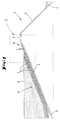
- dike 1 here a sea dike with an internal slope 2 and an external slope 3 and to some extent an internal range 4 and an external range 5.
- the prevailing storm surge water level is provided with the reference number 6.
- the outer slope 3 To secure and solidify the dike 1, in particular its sea side, are on the outer slope 3 in the embodiment shown three layers of net-like interconnected and pressed old vehicle tires 7 laid. These three layers are again network-like interconnected so that a spatial Formation is given to form a dike protection.
- This spatial network structure 8 extends further beyond the outer slope 3 beyond the outer slopes 5 and if necessary up to the foreshore.
- the network structure 8 runs in steps towards the dike crown 9 from, forming a single-layer, flat network structure 10.
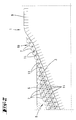
- Figures 1 and 2 is a tire assembly shown, which are partly flat and Part is spatially formed, according to the invention depicting a situation above and under water.
- the Transition from the spatial network structure 8 to the flat one Network structure 10 takes place in the area of the authoritative Storm surge water level 6.
- the spatial network structure 8 are also the individual ones Layers were preferably in the same way connected with each other. Such a structure moves a laminar flow of water in turbulence, which has the consequence that z. B. sand, silt, etc. not can be washed away, but due to the turbulent Flow stopped and into the spatial tire structure is stored. It comes to one desired burial effect in the underground.
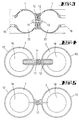
- FIG. 4 shows an alternative form of connection, in which a vehicle tire 7 'like a loop connects two further vehicle tires 7 together.
- the connecting vehicle tire 7 ' separated so that this one essentially has radially guided separating cut 15 (see. Fig. 10).
- the tire openings 16 of the to be connected Tire 7 are the two free ends under Overlap again in the area of the separation point connected, preferably a bolt here in accordance with the type described for FIG. 3 Is used (see Fig. 11).
- a movable connection of the Vehicle tires with each other also by means of a loop, like a wire loop 17 according to FIG. 5.
- a connection is still through Chain, wire or other clamp links conceivable.
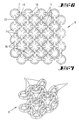
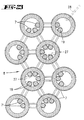
- 6 and 7 is a spatial arrangement of Tire 7 shown to form a spatial Network structure 8.
- the individual are preferred Tire 7 with and to each other through tire connections connected in the manner described with respect to FIG. 4.
- Such spatial network structures 8 are also by connecting the vehicle tires 7 to one another according to that described with reference to FIGS. 3 and 5 Connection training possible.
- the advantage of spatial Network structure 8 consists in the more generous so obtained Room volume as well as its better mobility compared to the underground, so an improved Adaptability. 6 and 7 shown way can, for example, the one in FIG. 1 below of the water level 6 shown spatial network structure 8 be formed.
- FIG. 8 and 9 show another embodiment a link-chain arrangement of vehicle tires 7, similar to the arrangement of FIG. 4. Here, however all vehicle tires 7 separated and after manufacture the loop-like connection back to one bolt-like structures bolted.
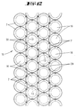
- FIG. 12 An exemplary, made from old vehicle tires 7 Flat network structure 10 is shown in FIG. 12.
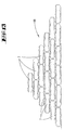
- FIG. Another application is shown in FIG.
- a dam core 18 pressed with concrete.
- a very stable dam core 18 is formed, which, according to the rubber layers of vehicle tires 7 is flexible enough in itself to occur To follow building and underground movements or take.
- Such tire embankments are also ideal where z. B. in shallow water areas for z. B. Islands for residential and vegetation purposes should take place.
- building atoll-like Tire walls can cover the outer tire layers remain uncompressed to with a suitable substrate to be backfilled for vegetation.
- each formed a rubber layer is to further increase the desired flexibility here to be able to increase.
- network structures 10 can also be connected to each other by bolts.
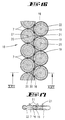
- Fig. 16 shows an arrangement in which each touch three vehicle tires 7 and press-bolt are interconnected to form one in itself rigid network.
- the vehicle tires are 7 fully grouted with concrete 19 inside.
- each vehicle tire 7 and each gusset 20 Filling nipple 21 assigned, for pressing in the concrete 19th
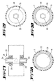
- FIGS. 18 and 19 a partial The vehicle tires 7 are pressed with concrete 19. Only the tire interior 22 is filled in here, in this one serving as a protective cover Fabric hose 23 is added.
- This ring-shaped Fabric hose 23 is with two inner, each Provide filling connections 24 forming compression nipples, wherein a nipple forms an inlet port 25 for Injection compound and the other nipple one Outlet port 26 for forwarding the molding compound represents further fabric hose bodies.
- This is advantageously the outlet port 26 of a Vehicle tire 7 with a connecting tube 27 the inlet port 25 of an adjacent vehicle tire 7 connected.
- the pressing with concrete or other Backfill material takes the form of one Concrete pump consisting of several grouting hoses for filling nipples 21 according to the embodiment in FIG. 16 or a Compression hose 28 to an inlet port 25 of a first fabric hose 23 leads. From here are the fabric tubes 23 of the other vehicle tires 7 connected in series by means of the connecting hoses 27.
- the between the vehicle tire 7 gusset formed by a a filling connection 24 having fabric hose Concrete 19 are pressed.
- the fabric hose 23 has an expansion ring 29 on the inside made of any material with a diameter equal to the inside diameter of the vehicle tire 7.
- a further alternative version is also a complete one Pressing the vehicle tires 7 is conceivable.
- This Fabric hose 23 also has two filling connections 24.
- the fabric hose 23 with concrete the entire tire diameter is filled in one operation filled in what in the area of the tire opening 16 a bubble-like bulging of the fabric tube 23 (see sectional view in Fig. 22).
- the fabric hose 23 used here is essentially as a double-sided, round fabric body formed, in contrast to that shown in Fig. 20 annular fabric hose 23 for backfilling only of the tire interior 22.
- FIG. 23 shows an arrangement of vehicle tires 7, which according to the embodiment of FIGS. 6 and 7 by a third, cut open vehicle tire 7 ' to form a spatial network structure 8 with one another are connected.
- these vehicle tires 7 with fabric tubes 23 provided which here with each other Hoses 27 shown in dash-dot lines are connected are.
- This arrangement is also via a compression hose 28 preferably pressed with concrete, so that the afterwards filled tire interior 22 a weighting form the entire network structure 8.
- FIG. 24 is in a further embodiment an arrangement shown in FIG. 23, but here Fabric tubes 23 are used, which is a complete Filling the vehicle tires, d. H. both of Tire interior 22 and the tire opening 16 effected according to the embodiment in Fig. 21.
- the gusset 20 between the Provide vehicle tires with additional fabric tubes 23 be, which also via connecting hoses 27 with the fabric tubes lying in the vehicle tires 7 23 are to be connected for pressing.
- FIG. 25 Another embodiment is shown in FIG. 25.
- a spatial network structure 8 according to 7 also penetrates as a protective cover 30 serving stockings 31.
- the arrangement is here chosen so that these fabric stockings 31 in extend substantially along a tire axis.
- These fabric stockings 31 are also not shown Compression hoses 28 filled with concrete so that after completing the grouting work, columnar concrete elements 32 are formed.
- 25 are only three fabric stockings 31 pressed into concrete elements 32 shown. In practice, however, there will be a variety such fabric stockings 31 inserted, with crossing points the fabric stockings 31 are consciously accepted. In the course of the pressing, these fit together on.
- the fabric stockings stored in the vehicle tires 7 31 are positioned so that they function expand so much in the compressed state according to FIG. 25 and partially attach each other so that a positive, non-positive and adhesive attachment of total Vehicle tires 7 and fabric stockings 31 or concrete elements 32 arises (see FIG. 26). In this way is according to the volume dimensions of another tire composite structure an essentially monolithic body reached, with the inner vehicle tires act in the manner of flexible reinforcement.
- FIG. 27 shows a cross section through a fabric tube 23 with an arranged connecting member 33, which 23 filling connections on the top and bottom of the fabric hose 24 trains. That in this embodiment
- the connecting link 33 shown can be, for example, in the middle Arrangement in one for complete squeezing a fabric tube 23 serving a vehicle tire 7 be provided.
- Both the link 33 shown and the clamping rings 35 can also be connected to rubber or Plastic tubes are used in the tire interior 22 arranged can serve as a float.
- FIG. 28 is a sectional view of one for Forming a network structure according to the invention Vehicle tire 7 shown, in the tire interior 22nd a float 36 in the form of a plastic or Rubber hose is inserted.
- a float 36 in the form of a plastic or Rubber hose is inserted.
- the inserted hoses are initially filled with air filled, serve accordingly as a buoyancy body 36.
- you can also use these plastic or rubber hoses serve for filling with concrete or the like.
- the vehicle tire 7 shown in FIG. 29 has an axially arranged fabric hose 23 for Pressing purposes, as already described above.
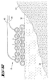
- the bank area is designated by reference number 37, the water surface at 38 and the lake floor at 39 quantified. Those not shown lie in the bank area 37 Vehicle tires 7 for the production of here spatial network structure 8 ready. Beyond that in the bank area 37 also the pressing accessories, such as. a compressor, available.
- One is used to produce the spatial network structure 8 Floating mounting platform forming a support device 40 41 provided.
- the latter has a working floor area 42 on the underside of floating elements 43 are provided. You can use pontoons or serve barrels.
- rolling elements 44 are provided on the working floor surface 42 .
- the latter can used steel barrel hoops, through which a scaffold tube is inserted as a supporting axis.
- alternative can also be used as rolling elements 44 here (old) vehicle tires be used.
- the bank area 37 40 On the side of the carrying device facing the bank area 37 40 starts at the one marked A. Place and assemble the individual vehicle tires 7 together. In the embodiment shown is a connection of the tires 7 to each other by others Vehicle tires 7 'are provided. However, it is also any other alternative connection type as before described, conceivable. The assembly can be done in Bank area 37 take place, after which completed sections rolled over the carrying device 40 seaward become. However, there is also the option of To produce network structure 8 directly on the support device 40.
- hoses serving as buoyancy bodies 36 and with fabric hoses 23 and / or fabric stockings 31 Mistake. Both the buoyancy tubes and the Tissue hoses 23 are described via connection hoses at least partially connected.
- the vehicle tires the top layer of the three-dimensional network structure 8 provided with compression hoses 28, which in Bank area 37 with the compressor stationed there are connected.
- the network structure 8 is finished while draining one Section (see position B in Fig. 31) the water surface 38 is drained (see C in Fig. 31).
- the carrying device 40 acts in the manner of a loom.
- the mounted vehicle tires 7 remain on the water surface 38 where by means of the described, filled with air Buoyancy body 36 first on the water surface swim.
- control tubes 45 provided which one end with the network structure 8 or with fabric hoses 23 / fabric stockings 31 connected and elsewhere with above the water level visible control stockings 50 are provided.
- the latter are preferably made from a fabric; more preferably made of the same material as that Hoses / stockings.
- control hoses 45 or control stockings 50 is the state in the course of pressing the network structure observable.
- Fig. 33 shows the lowered position of the network structure 8 on the lake floor 39, which is why in the buoyancy bodies 36 existing air cushions are preferably remote controlled are degraded. This happens, for example, by opening one Valve or in the simplest way during an apprenticeship the buoyancy body 36 in the form of plastic or Rubber hoses by destroying them.
- Network structure 8 is connected via the Compression hoses 38 from the bank area 37 with concrete or the like compressible, the full volume Compression even under water over the above water control stockings 50 is checked. Due to the flexible design of the network structure these adapt to the surface conditions.
- Concrete bodies of any thickness can be created using this Technology can be created, with the enveloping or internal vehicle tires 7 a flexible effective reinforcement is given.
- a flexible effective reinforcement is given.
- the targeted Pressing technology is possible at any desired location and at any water depth, where appropriate the Pressing from a floating assembly platform 41 is made from a flawless and by For example, to produce seawater not contaminated concrete.
- underwater work such as the production of new reefs or Islands, conveniently from the water surface or from the bank area remotely controlled via the compression hoses 28 respectively.
- compression hoses 28 respectively.
- Compression nipples and hoses are preferred.
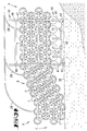
- a spatial network structure 8 which has a greater height. This will be four layers of vehicle tires 7 arranged one above the other further tires to a three-dimensional, flexible Structure connected.
- the support device 40 is accordingly provided with a framework 46, which Commercially available scaffold tubes 47 and scaffold connectors 48 composed.
- FIG. 35 is a completed one Construction shown.
- the vehicle tires 7 to form a ring wall 49 in cross section arranged like a truncated cone.
- the tire interior 22, the tire openings 16 and the gusset 20 are with Provide fabric hoses 23 and pressed with concrete.
- these are network structures can be used to create artificially building islands in shallow water areas.
- such ring walls 49 also for wharfs on Halligen or other islands as well as for port facilities.
- Such a lowered tire structure can be used also serve as a ring atoll or reef.
- An alternative to backfilling with concrete is to achieve vegetation, e.g. under water, conceivable, substrates, mixed with the corresponding plant germs or Seeds to press. Furthermore, the light can Gaps inside and outside the vehicle tires 7 to be filled with humus or topsoil, too this is the basis for vegetation.
Landscapes
- Engineering & Computer Science (AREA)
- General Engineering & Computer Science (AREA)
- Environmental & Geological Engineering (AREA)
- Ocean & Marine Engineering (AREA)
- Mechanical Engineering (AREA)
- Civil Engineering (AREA)
- Structural Engineering (AREA)
- Revetment (AREA)
- Tires In General (AREA)
- Investigation Of Foundation Soil And Reinforcement Of Foundation Soil By Compacting Or Drainage (AREA)
- Agricultural Machines (AREA)
Description
- Fig. 1
- eine schematische Querschnittsdarstellung durch einen Seedeich mit einer auf der Außenböschung angeordneten Netzstruktur von Fahrzeugreifen;
- Fig. 2
- eine Herausvergrößerung gemäß dem Bereich II in Fig. 1;
- Fig. 3
- eine Querschnittsdarstellung durch einen Verbindungsbereich zwischen zwei Fahrzeugreifen, wobei diese durch Verbolzung miteinander verbunden sind;
- Fig. 4
- eine Reifenanordnung, bei welcher ein Fahrzeugreifen schlingenartig zwei weitere miteinander verbindet;
- Fig. 5
- eine Reifenanordnung, bei welcher die Verbindung zweier Fahrzeugreifen vermittels einer Schlinge erfolgt;
- Fig. 6
- eine Draufsicht auf eine räumliche Netzstruktur von Fahrzeugreifen, bei einer gewählten Verbindung gemäß Fig. 4;
- Fig. 7
- eine schematische perspektivische Darstellung der räumlichen Netzstruktur gemäß Fig. 6;
- Fig. 8
- eine weitere Verbindungsanordnung von Fahrzeugreifen in einer Ansicht;
- Fig. 9
- die Draufsicht zu Fig. 8;
- Fig. 10
- einen aufgetrennten Fahrzeugreifen in Ansicht;
- Fig. 11
- den Fahrzeugreifen gemäß Fig. 10, wobei unter Überlappung an der Trennstelle der Fahrzeugreifen wieder kreisringförmig geschlossen ist, partiell geschnitten;
- Fig. 12
- eine flächige Anordnung von Alt-Fahrzeugreifen, welche untereinander über ihre Laufflächen verbolzt sind;
- Fig. 13
- einen, aus übereinander geschichteten Netzstrukturen gebildeten Damm;
- Fig. 14
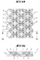
- eine Draufsicht auf eine Netzstrukturanordnung, bei welcher lotrechte Schichten übereinander versetzt gelagert sind;
- Fig. 15
- den Schnitt gemäß der Linie XV-XV in Fig. 14, wobei die Fahrzeugreifen mit Beton verpreßt sind;
- Fig. 16
- eine einlagige Anordnung einer Netzstruktur in einer geschnittenen Darstellung, bei welcher sowohl die Reifeninnenräume als auch die zwischen den Reifen gebildeten Zwickel mit Beton verpreßt sind;
- Fig. 17
- den Schnitt gemäß der Linie XVII-XVII in Fig. 16;
- Fig. 18
- eine der Fig. 16 entsprechende Schnittdarstellung, wobei hier jedoch lediglich die Reifeninnenräume vermittels eingelegter Gewebeschläuche verfüllt sind;
- Fig. 19
- den Schnitt gemäß der Linie XIX-XIX in Fig. 18, in vergrößerter Darstellung;
- Fig. 20
- einen Gewebeschlauch im Querschnitt;
- Fig. 21
- eine der Fig. 18 entsprechende Darstellung, jedoch bei vollständiger Verpressung des Fahrzeugreifens, einschließlich der freien Reifenöffnung mit Beton;
- Fig. 22
- den Schnitt gemäß der Linie XXII-XXII in Fig. 21;
- Fig. 23
- eine Schnittdarstellung einer räumlichen Netzstruktur bei einer Verbindung der Fahrzeugreifen gemäß Fig. 4, wobei die Reifeninnenräume mittels eingelegter Gewebeschläuche verpreßt sind;
- Fig. 24
- eine der Fig. 23 entsprechende Darstellung, bei vollständiger Verpressung über eingelegte Gewebeschläuche;
- Fig. 25
- eine der Fig. 7 entsprechende Darstellung, bei Durchsetzung der Fahrzeugreifen mit säulenartigen Betonelementen;
- Fig. 26
- den Schnitt gemäß der Linie XXVI-XXVI in Fig. 25;
- Fig. 27
- einen Querschnitt durch einen zu verpressenden Gewebeschlauch;
- Fig. 28
- im Schnitt einen Fahrzeugreifen mit innenliegendem Plastik- oder Gummischlauch als Auftriebskörper;
- Fig. 29
- den Fahrzeugreifen mit innenliegendem Gewebeschlauch für die Verpressung;
- Fig. 30
- den Fahrzeugreifen mit Auftriebskörper und Gewebeschlauch;
- Fig. 31
- eine schematische Darstellung der Herstellung einer erfindungsgemäßen Netzstruktur auf einem schwimmenden Traggestell;
- Fig. 32
- die fertiggestellte Netzstruktur auf dem Wasser schwimmend, gegenüber der Fig. 31 eine alternative Ausführungsform der Netzstruktur betreffend;
- Fig. 33
- die auf den Meeresboden abgesenkte Netzstruktur;
- Fig. 34
- eine der Fig. 31 entsprechende Darstellung, jedoch eine alternative Ausgestaltung der Netzstruktur und des Traggestells betreffend;
- Fig. 35
- eine schematische Schnittdarstellung eines mit der erfindungsgemäßen Netzstruktur erstellten Ringwalls.
Claims (36)
- Verfahren zur Sicherung, Verfestigung sowie Neugewinnung von Bodenflächen und Untergründen über und unter Wasser, wobei die Sicherung durch bevorzugt netzartig miteinander verbundene (Alt-) Fahrzeugreifen und eine Beschwerung mittels Verfülmasse wie Beton (19) durchgeführt wird, dadurch gekennzeichnet, dass die Verfülmasse wie Beton (19) vor Ort in einen Gewebeschlauch (23, 31), der in einem Reifeninnenraum aufgenommen ist, eingepresst wird.
- Verfahren nach Anspruch 1, dadurch gekennzeichnet, dass die Fahrzeugreifen (7) zunächst netzartig miteinander verbunden werden und sodann auf eine zu sichernde Bodenfläche aufgelegt oder eingebracht werden.
- Verfahren nach einem oder mehreren der vorhergehenden Ansprüche, dadurch gekennzeichnet, dass die Fahrzeugreifen (7) nach Auflage auf die Bodenfläche verfüllt werden.
- Verfahren nach einem oder mehreren der vorhergehenden Ansprüche, dadurch gekennzeichnet, dass die Fahrzeugreifen (7) mit Beton (19) verpresst werden.
- Verfahren nach einem oder mehreren der vorhergehenden Ansprüche, dadurch gekennzeichnet, dass die Fahrzeugreifen (7) mit Erde ausgefüllt werden.
- Verfahren nach einem oder mehreren der vorhergehenden Ansprüche, dadurch gekennzeichnet, dass die netzartige Verbindung als räumliche Struktur mehrerer Lagen von Fahrzeugreifen (7) ausgeführt ist.
- Verfahren nach einem oder mehreren der vorhergehenden Ansprüche, dadurch gekennzeichnet, dass die Netzstruktur (8, 10) auf einer schwimmfähigen Tragvorrichtung (40) erstellt wird.
- Verfahren nach einem oder mehreren der vorhergehenden Ansprüche, dadurch gekennzeichnet, dass die Netzstruktur (8, 10) kontinuierlich unter Ablassen eines fertiggestellten Abschnitts auf eine Wasserfläche (38) erstellt wird.
- Verfahren nach einem oder mehreren der vorhergehenden Ansprüche, dadurch gekennzeichnet, dass die Netzstruktur (8, 10) mit Auftriebskörpern (36) ausgerüstet wird.
- Verfahren nach einem oder mehreren der vorhergehenden Ansprüche, dadurch gekennzeichnet, dass das Verpressen mit Beton (19) nach Auflage auf einer Bodenfläche (39) unter Wasser durchgeführt wird.
- Verfahren nach einem oder mehreren der vorhergehenden Ansprüche, dadurch gekennzeichnet, dass im Zuge der Erstellung der Netzstruktur(8, 10) auch eine Verbindung von Verpressschläuchen (28) durchgeführt wird.
- Verfahren nach einem oder mehreren der vorhergehenden Ansprüche, dadurch gekennzeichnet, dass eine vollständige Verpressung über und unter Wasser über einen Kontrollschlauch (45) kontrolliert wird.
- Deich (1), wie ein Seedeich oder Flussteich, mit einer Außenböschung (3) und einer Innenböschung (2), wobei die Außenböschung (3) und/oder die Innenböschung (2) durch aufliegende, untereinander zu einer Netzstruktur (8, 10) verbundene Fahrzeugreifen (7) gesichert ist, dadurch gekennzeichnet, dass in einem Reifeninnenraum in einem Gewebeschlauch (23, 31) verpresste Verfüllmasse wie Beton enthalten ist.
- Deich nach Anspruch 13, dadurch gekennzeichnet, dass die Netzstruktur (8) mehrlagig ist.
- Deich nach einem oder mehreren der Ansprüche 13 bis 14, dadurch gekennzeichnet, dass die Netzstruktur (8, 10) zur Deichkrone (9) hin abgestuft ausläuft.
- Deich nach einem oder mehreren der Ansprüche 13 bis 15, dadurch gekennzeichnet, dass die Netzstruktur (8, 10) über die Böschung (2, 3)hinaus sich bis in das Vorland erstreckt.
- Netzstruktur (8, 10) von Fahrzeugreifen (7) zur Verwendung in einem Verfahren nach den Ansprüchen 1 bis 12 oder zur Ausbildung eines Deiches (1) nach den Ansprüchen 13 bis 16, dadurch gekennzeichnet, dass die Netzstruktur (8, 10) mittels in einer als Gewebeschlauch (22, 31) ausgebildeten, in einem Innenraum sich befindlichen, Schutzhülle (30) verpressten Verfüllmasse wie Beton (19) beschwert ist.
- Netzstruktur nach Anspruch 17, dadurch gekennzeichnet, dass die Schutzhülle (30) wasserundurchlässig ist.
- Netzstruktur nach einem oder mehreren der Ansprüche 17 bis 18, dadurch gekennzeichnet, dass das in der Schutzhülle (30) verpresste Betonelement (32) den Fahrzeugreifen (7) in Achsrichtung durchsetzt.
- Netzstruktur nach einem oder mehreren der Ansprüche 17 bis 19, dadurch gekennzeichnet, dass die Betonelemente (32) durch Verpressen in einem kraft- und/oder formschlüssigen Verbund mit den Fahrzeugreifen (7) sind.
- Netzstruktur nach einem oder mehreren der Ansprüche 17 bis 20, dadurch gekennzeichnet, dass zwei Fahrzeugreifen (7) unter Duchsetzung der Laufflächen (12) miteinader verbolzt sind.
- Netzstruktur nach einem oder mehreren der Ansprüche 17 bis 21, dadurch gekennzeichnet, dass zwei Fahrzeugreifen (7) mittels einer Schlinge, wie einer Drahtschlinge (17), miteinander verbunden sind.
- Netzstruktur nach einem oder mehreren der Ansprüche 17 bis 22, dadurch gekennzeichnet, dass ein Fahrzeugreifen (7') schlingenartig zwei weitere Fahrzeugreifen (7) miteinander verbindet.
- Netzstruktur nach einem oder mehreren der Ansprüche 17 bis 23, dadurch gekennzeichnet, dass der verbindende Fahrzeugreifen (7') oder die verbundenen Fahrzeugreifen (7) aufgetrennt und wieder miteinander verbunden sind.
- Netzstruktur nach einem oder mehreren der Ansprüche 17 bis 24, dadurch gekennzeichnet, dass die aufgetrennten Fahrzeugreifen (7) einen im Wesentlichen radial geführten Trennschnitt (15) aufweisen und unter Überlappung an der Trennstelle wieder miteinander verbunden sind.
- Netzstruktur nach einem oder mehreren der Ansprüche 17 bis 25, dadurch gekennzeichnet, dass ein Fahrzeugreifen (7) mit mindestens zwei weiteren Fahrzeugreifen (7) verbunden ist.
- Netzstruktur nach einem oder mehreren der Ansprüche 17 bis 26, dadurch gekennzeichnet, dass der Beton (19) den Fahrzeugreifen (7) vollständig, einschließlich der freien Reifenöffnung (16) ausfüllt.
- Netzstruktur nach einem oder mehreren der Ansprüche 17 bis 27, dadurch gekennzeichnet, dass in dem Fahrzeugreifen (7) ein, den gesamten Reifendurchmesser ausfüllender, mit Beton (19) verpresster Gewebeschlauch (23) aufgenommen ist.
- Netzstruktur nach einem oder mehreren der Ansprüche 17 bis 28, dadurch gekennzeichnet, dass ein Gewebeschlauch (23) einen Füllanschluß (24) aufweist.
- Netzstruktur nach einem oder mehreren der Ansprüche 17 bis 29, dadurch gekennzeichnet, dass ein Gewebeschlauch (23) zwei Füllanschlüsse (24) als Ein- und Auslassanschlüsse (25, 26) aufweist.
- Netzstruktur nach einem oder mehreren der Ansprüche 17 bis 30, dadurch gekennzeichnet, dass an einem Füllanschluss (24) ein Kontrollschlauch (45) angeschlossen ist.
- Netzstruktur nach einem oder mehreren der Ansprüche 17 bis 31, dadurch gekennzeichnet, dass an dem Kontrollschlauch (45) ein mit Beton (19) verpresster Kontrollstrumpf (50) angeordnet ist.
- Netzstruktur nach einem oder mehreren der Ansprüche 17 bis 32, dadurch gekennzeichnet, dass bei einem flächigen Aneinanderlegen von Fahrzeugreifen (7) entstehende Zwickel (20) mit Beton (19) verfüllt sind.
- Netzstruktur nach einem oder mehreren der Ansprüche 17 bis 33, dadurch gekennzeichnet, dass die Zwickel (20) durch einen, einen Füllanschluss (24) aufweisenden Gewebeschlauch (23) mit Beton (19) verpresst werden.
- Netzstruktur nach einem oder mehreren der Ansprüche 17 bis 34, dadurch gekennzeichnet, dass in dem Gewebeschlauch (23) ein Spreizring (29) angeordnet ist.
- Netzstruktur nach einem oder mehreren der Ansprüche 17 bis 35, dadurch gekennzeichnet, dass die Verfüllmasse ein Substrat ist, vermischt mit Pflanzenkeimen und/oder Pflanzensamen.
Applications Claiming Priority (5)
| Application Number | Priority Date | Filing Date | Title |
|---|---|---|---|
| DE19740294 | 1997-09-13 | ||
| DE19740294 | 1997-09-13 | ||
| DE19752794 | 1997-11-28 | ||
| DE1997152794 DE19752794A1 (de) | 1997-09-13 | 1997-11-28 | Verfahren zur Sicherung, Verfestigung sowie Neugewinnung von Bodenflächen und Untergründen über und unter Wasser |
| PCT/EP1998/005761 WO1999014440A1 (de) | 1997-09-13 | 1998-09-11 | Verfahren zur sicherung, verfestigung sowie neugewinnung von bodenflächen und untergründen über und unter wasser |
Publications (2)
| Publication Number | Publication Date |
|---|---|
| EP1012402A1 EP1012402A1 (de) | 2000-06-28 |
| EP1012402B1 true EP1012402B1 (de) | 2002-07-10 |
Family
ID=26039951
Family Applications (1)
| Application Number | Title | Priority Date | Filing Date |
|---|---|---|---|
| EP98954269A Expired - Lifetime EP1012402B1 (de) | 1997-09-13 | 1998-09-11 | Verfahren zur sicherung, verfestigung sowie neugewinnung von bodenflächen und untergründen über und unter wasser |
Country Status (7)
| Country | Link |
|---|---|
| US (1) | US6375387B1 (de) |
| EP (1) | EP1012402B1 (de) |
| AT (1) | ATE220435T1 (de) |
| AU (1) | AU747316B2 (de) |
| DE (1) | DE29824577U1 (de) |
| ES (1) | ES2179541T3 (de) |
| WO (1) | WO1999014440A1 (de) |
Families Citing this family (15)
| Publication number | Priority date | Publication date | Assignee | Title |
|---|---|---|---|---|
| AU761614B2 (en) * | 1998-08-06 | 2003-06-05 | Ecoflex Limited | Tyre foundation structure |
| GB2368363B (en) * | 2000-10-27 | 2005-03-16 | Anthony Robinson | Method of disposing of used vehicle tyres |
| US6705803B2 (en) * | 2001-05-17 | 2004-03-16 | Garry Kevin Callinan | Tire foundation structure |
| US20030223826A1 (en) * | 2002-03-21 | 2003-12-04 | Ianniello Peter J. | Synthetic alternatives to uniform and non-uniform gradations of structural fill |
| WO2003097964A2 (en) * | 2002-05-16 | 2003-11-27 | Talbott Alex F | Tire fence |
| KR20040025152A (ko) * | 2002-09-18 | 2004-03-24 | 허수영 | 하천제방용 세굴방지재의 시공방법 |
| US6929422B2 (en) * | 2003-04-21 | 2005-08-16 | Frank E. Pearce | Shore protective barrier system |
| GB2405169A (en) * | 2003-08-22 | 2005-02-23 | Joseph Toland | Marine structure formed from clamped tyre beads |
| US7066684B1 (en) * | 2004-06-24 | 2006-06-27 | Bourgeois William P | Silt restoration device |
| CN1320212C (zh) * | 2004-11-23 | 2007-06-06 | 周明辉 | 废轮胎砖施工方法及装置 |
| CA2594063A1 (en) * | 2004-12-24 | 2006-06-29 | Tyrecom Nz Limited | Tyre placement and pilling apparatus and method |
| GB2467376A (en) * | 2009-02-03 | 2010-08-04 | Roland Eddie Todd | Groyne made with tyre bales |
| GB0903068D0 (en) * | 2009-02-24 | 2009-04-08 | Durrant Robert H | Anti scour mats |
| RU2541993C2 (ru) * | 2010-05-17 | 2015-02-20 | Арматерра, Инк. | Геоармирующая система на основе шин |
| CN110205979B (zh) * | 2019-04-03 | 2024-08-20 | 宜宾学院 | 一种资源化利用型的人工沙质海岸防护设施及其施工方法 |
Family Cites Families (20)
| Publication number | Priority date | Publication date | Assignee | Title |
|---|---|---|---|---|
| US3842606A (en) | 1969-02-04 | 1974-10-22 | G Dunan | Beach-protectors |
| US4080793A (en) | 1975-04-10 | 1978-03-28 | Pulsifer Ernest K | Method and apparatus for using automotive tires as earth engineering devices |
| US4188153A (en) | 1976-03-31 | 1980-02-12 | Taylor John E | Formation of barriers |
| US4139319A (en) | 1977-12-29 | 1979-02-13 | Emmett C. Anderson | Motor vehicle rubber tires and concrete revetment |
| US4150909A (en) | 1978-01-09 | 1979-04-24 | Daniel David W | Breakwater system |
| US4196694A (en) * | 1978-02-09 | 1980-04-08 | Buchanan Robert R | Artificial reef elements and method of deploying same |
| US4334499A (en) * | 1980-11-19 | 1982-06-15 | Baass Allen J | Artificial reef construction |
| US4406241A (en) * | 1982-03-03 | 1983-09-27 | Robert Comte | Device for absorbing friction between ship's hulls and the quay walls |
| NL8800644A (nl) * | 1988-03-16 | 1989-10-16 | Acz Marine Contractors B V | Werkwijze voor het vullen en op hun plaats aanbrengen van met stortgoed gevulde slangvormige lichamen. |
| FR2643400A1 (fr) * | 1989-02-22 | 1990-08-24 | Chevalier Expl Ets | Procede de stabilisation superficielle des sols ou des ouvrages soumis a l'erosion hydraulique |
| US5056961A (en) | 1990-05-23 | 1991-10-15 | Mcmeans John D | Method of constructing walls from discarded tires |
| US5024560A (en) * | 1990-06-04 | 1991-06-18 | Reilly Joseph W | Method and apparatus for protection against coastal erosion |
| DE69118186D1 (de) * | 1990-07-05 | 1996-04-25 | Anthony Peter Sorrell | Bauwerke aus gebrauchten fahrzeugreifen |
| JP2808192B2 (ja) * | 1991-01-25 | 1998-10-08 | 清水建設株式会社 | 生分解性プラスチック製土のう袋、同土のう袋を用いた土のう及び同土のうによる埋立方法 |
| US5143484A (en) * | 1991-02-26 | 1992-09-01 | Maurice Deul | Mine cribbing device and method |
| US5370476A (en) * | 1991-08-23 | 1994-12-06 | Streichenberger; Rodolophe | Self anchoring tire-made artificial reef |
| GB2267724A (en) * | 1992-06-09 | 1993-12-15 | Ronald Ernest Southey | Structures incorporating used vehicle tyres |
| US5364206A (en) * | 1993-09-29 | 1994-11-15 | Marienfeld Mark L | Soil stabilization system |
| US5370475A (en) * | 1993-10-25 | 1994-12-06 | Leblanc; Louis P. | Erosion barrier system made from tires |
| US6213687B1 (en) * | 1999-07-30 | 2001-04-10 | Amos Washington Broughton | System for preventing erosion of soil surfaces |
-
1998
- 1998-09-11 AT AT98954269T patent/ATE220435T1/de not_active IP Right Cessation
- 1998-09-11 WO PCT/EP1998/005761 patent/WO1999014440A1/de not_active Ceased
- 1998-09-11 ES ES98954269T patent/ES2179541T3/es not_active Expired - Lifetime
- 1998-09-11 AU AU11461/99A patent/AU747316B2/en not_active Ceased
- 1998-09-11 US US09/508,652 patent/US6375387B1/en not_active Expired - Fee Related
- 1998-09-11 EP EP98954269A patent/EP1012402B1/de not_active Expired - Lifetime
- 1998-09-11 DE DE29824577U patent/DE29824577U1/de not_active Expired - Lifetime
Also Published As
| Publication number | Publication date |
|---|---|
| ATE220435T1 (de) | 2002-07-15 |
| DE29824577U1 (de) | 2001-09-27 |
| US6375387B1 (en) | 2002-04-23 |
| AU1146199A (en) | 1999-04-05 |
| WO1999014440A1 (de) | 1999-03-25 |
| AU747316B2 (en) | 2002-05-16 |
| EP1012402A1 (de) | 2000-06-28 |
| ES2179541T3 (es) | 2003-01-16 |
Similar Documents
| Publication | Publication Date | Title |
|---|---|---|
| WO2009129809A2 (de) | Vorrichtung und verfahren für den hochwasser-, küsten- oder kolkschutz | |
| DE3152098C2 (de) | ||
| DE69628299T2 (de) | Uferhochwasserschutzwand | |
| DE69737147T2 (de) | Erosionskontrollmethode durch konstruktion einer deckschicht und produktionsmethode zur verhinderung von erdrutschen | |
| DE29824577U1 (de) | Deich, Netzstruktur von Fahrzeugreifen und Montageplattform | |
| US4080793A (en) | Method and apparatus for using automotive tires as earth engineering devices | |
| EP1011944B1 (de) | Verfahren und vorrichtung zum verarbeiten von reifen | |
| WO2017089244A1 (de) | Schutzvorrichtung | |
| AT352639B (de) | Uferverbau | |
| EP1911885B1 (de) | Erosionsschutzmatratze | |
| DE19752794A1 (de) | Verfahren zur Sicherung, Verfestigung sowie Neugewinnung von Bodenflächen und Untergründen über und unter Wasser | |
| DE102016201023A1 (de) | Vorrichtung zum Erstellen eines Unterwasserbauwerks, Filtereinrichtung für eine entsprechende Vorrichtung und Verfahren zum Erstellen eines Unterwasserbauwerks | |
| EP1937898A1 (de) | Schutzwand, deich und verfahren zur herstellung eines deiches | |
| DE10313974B4 (de) | Erdwall mit Rasendeckung, insbesondere Deich | |
| JP4024064B2 (ja) | 護岸構造物及び護岸工法 | |
| DE4344703A1 (de) | Erdbauwerk | |
| Garanaik et al. | River Bank Protection | |
| DE3718805A1 (de) | Betonfertigteil | |
| DE202006015421U1 (de) | Erosionsschutzmatratze | |
| DE60018985T2 (de) | Verfahren zum aufbau eines systems zum schutz vor überschwemmungen | |
| DE102009055621A1 (de) | Erdwall, insbesondere Deich oder Damm, Verfahren zur Herstellung desselben und Verfahren zur Abdichtung oder Andichtung von Bauwerken | |
| DE102013109216A1 (de) | Kolkschutzmatte | |
| DE102012106568A1 (de) | Dammstabilisierungsverfahren | |
| DE3214648A1 (de) | Verfahren zur gruendungsherstellung von schalenfoermigen behaeltern | |
| DE10037320C2 (de) | Verfahren und Vorrichtungen zum Verlegen eines aus einer Anzahl von Rohren bestehenden Rohrstrangs in einer Rinne am Boden eines Gewässers |
Legal Events
| Date | Code | Title | Description |
|---|---|---|---|
| PUAI | Public reference made under article 153(3) epc to a published international application that has entered the european phase |
Free format text: ORIGINAL CODE: 0009012 |
|
| 17P | Request for examination filed |
Effective date: 20000331 |
|
| AK | Designated contracting states |
Kind code of ref document: A1 Designated state(s): AT BE CH CY DE DK ES FI FR GB GR IE IT LI LU MC NL PT SE |
|
| AX | Request for extension of the european patent |
Free format text: AL PAYMENT 20000331;LT PAYMENT 20000331;LV PAYMENT 20000331;MK PAYMENT 20000331;RO PAYMENT 20000331;SI PAYMENT 20000331 |
|
| 17Q | First examination report despatched |
Effective date: 20001023 |
|
| GRAG | Despatch of communication of intention to grant |
Free format text: ORIGINAL CODE: EPIDOS AGRA |
|
| GRAG | Despatch of communication of intention to grant |
Free format text: ORIGINAL CODE: EPIDOS AGRA |
|
| GRAH | Despatch of communication of intention to grant a patent |
Free format text: ORIGINAL CODE: EPIDOS IGRA |
|
| GRAH | Despatch of communication of intention to grant a patent |
Free format text: ORIGINAL CODE: EPIDOS IGRA |
|
| GRAA | (expected) grant |
Free format text: ORIGINAL CODE: 0009210 |
|
| AK | Designated contracting states |
Kind code of ref document: B1 Designated state(s): AT BE CH CY DE DK ES FI FR GB GR IE IT LI LU MC NL PT SE |
|
| AX | Request for extension of the european patent |
Free format text: AL PAYMENT 20000331;LT PAYMENT 20000331;LV PAYMENT 20000331;MK PAYMENT 20000331;RO PAYMENT 20000331;SI PAYMENT 20000331 |
|
| PG25 | Lapsed in a contracting state [announced via postgrant information from national office to epo] |
Ref country code: NL Free format text: LAPSE BECAUSE OF FAILURE TO SUBMIT A TRANSLATION OF THE DESCRIPTION OR TO PAY THE FEE WITHIN THE PRESCRIBED TIME-LIMIT Effective date: 20020710 Ref country code: IE Free format text: LAPSE BECAUSE OF FAILURE TO SUBMIT A TRANSLATION OF THE DESCRIPTION OR TO PAY THE FEE WITHIN THE PRESCRIBED TIME-LIMIT Effective date: 20020710 Ref country code: GR Free format text: LAPSE BECAUSE OF FAILURE TO SUBMIT A TRANSLATION OF THE DESCRIPTION OR TO PAY THE FEE WITHIN THE PRESCRIBED TIME-LIMIT Effective date: 20020710 Ref country code: FI Free format text: LAPSE BECAUSE OF FAILURE TO SUBMIT A TRANSLATION OF THE DESCRIPTION OR TO PAY THE FEE WITHIN THE PRESCRIBED TIME-LIMIT Effective date: 20020710 |
|
| REF | Corresponds to: |
Ref document number: 220435 Country of ref document: AT Date of ref document: 20020715 Kind code of ref document: T |
|
| REG | Reference to a national code |
Ref country code: GB Ref legal event code: FG4D Free format text: NOT ENGLISH |
|
| REG | Reference to a national code |
Ref country code: CH Ref legal event code: EP |
|
| REG | Reference to a national code |
Ref country code: IE Ref legal event code: FG4D Free format text: GERMAN |
|
| REF | Corresponds to: |
Ref document number: 59804741 Country of ref document: DE Date of ref document: 20020814 |
|
| PG25 | Lapsed in a contracting state [announced via postgrant information from national office to epo] |
Ref country code: LU Free format text: LAPSE BECAUSE OF NON-PAYMENT OF DUE FEES Effective date: 20020911 Ref country code: AT Free format text: LAPSE BECAUSE OF NON-PAYMENT OF DUE FEES Effective date: 20020911 |
|
| PG25 | Lapsed in a contracting state [announced via postgrant information from national office to epo] |
Ref country code: LI Free format text: LAPSE BECAUSE OF NON-PAYMENT OF DUE FEES Effective date: 20020930 Ref country code: CY Free format text: LAPSE BECAUSE OF FAILURE TO SUBMIT A TRANSLATION OF THE DESCRIPTION OR TO PAY THE FEE WITHIN THE PRESCRIBED TIME-LIMIT Effective date: 20020930 Ref country code: CH Free format text: LAPSE BECAUSE OF NON-PAYMENT OF DUE FEES Effective date: 20020930 Ref country code: BE Free format text: LAPSE BECAUSE OF NON-PAYMENT OF DUE FEES Effective date: 20020930 |
|
| PG25 | Lapsed in a contracting state [announced via postgrant information from national office to epo] |
Ref country code: SE Free format text: LAPSE BECAUSE OF FAILURE TO SUBMIT A TRANSLATION OF THE DESCRIPTION OR TO PAY THE FEE WITHIN THE PRESCRIBED TIME-LIMIT Effective date: 20021010 Ref country code: PT Free format text: LAPSE BECAUSE OF FAILURE TO SUBMIT A TRANSLATION OF THE DESCRIPTION OR TO PAY THE FEE WITHIN THE PRESCRIBED TIME-LIMIT Effective date: 20021010 Ref country code: DK Free format text: LAPSE BECAUSE OF FAILURE TO SUBMIT A TRANSLATION OF THE DESCRIPTION OR TO PAY THE FEE WITHIN THE PRESCRIBED TIME-LIMIT Effective date: 20021010 |
|
| GBT | Gb: translation of ep patent filed (gb section 77(6)(a)/1977) |
Effective date: 20021010 |
|
| NLV1 | Nl: lapsed or annulled due to failure to fulfill the requirements of art. 29p and 29m of the patents act | ||
| ET | Fr: translation filed | ||
| LTIE | Lt: invalidation of european patent or patent extension |
Effective date: 20020710 |
|
| REG | Reference to a national code |
Ref country code: ES Ref legal event code: FG2A Ref document number: 2179541 Country of ref document: ES Kind code of ref document: T3 |
|
| REG | Reference to a national code |
Ref country code: IE Ref legal event code: FD4D Ref document number: 1012402E Country of ref document: IE |
|
| BERE | Be: lapsed |
Owner name: *SCHARPING DIETER Effective date: 20020930 Owner name: *GABOR THOMAS Effective date: 20020930 |
|
| PG25 | Lapsed in a contracting state [announced via postgrant information from national office to epo] |
Ref country code: MC Free format text: LAPSE BECAUSE OF NON-PAYMENT OF DUE FEES Effective date: 20030401 |
|
| REG | Reference to a national code |
Ref country code: CH Ref legal event code: PL |
|
| PLBE | No opposition filed within time limit |
Free format text: ORIGINAL CODE: 0009261 |
|
| STAA | Information on the status of an ep patent application or granted ep patent |
Free format text: STATUS: NO OPPOSITION FILED WITHIN TIME LIMIT |
|
| 26N | No opposition filed |
Effective date: 20030411 |
|
| PGFP | Annual fee paid to national office [announced via postgrant information from national office to epo] |
Ref country code: DE Payment date: 20070906 Year of fee payment: 10 |
|
| PGFP | Annual fee paid to national office [announced via postgrant information from national office to epo] |
Ref country code: GB Payment date: 20070927 Year of fee payment: 10 |
|
| PGFP | Annual fee paid to national office [announced via postgrant information from national office to epo] |
Ref country code: IT Payment date: 20070927 Year of fee payment: 10 Ref country code: ES Payment date: 20070905 Year of fee payment: 10 |
|
| PGFP | Annual fee paid to national office [announced via postgrant information from national office to epo] |
Ref country code: FR Payment date: 20070904 Year of fee payment: 10 |
|
| GBPC | Gb: european patent ceased through non-payment of renewal fee |
Effective date: 20080911 |
|
| REG | Reference to a national code |
Ref country code: FR Ref legal event code: ST Effective date: 20090529 |
|
| PG25 | Lapsed in a contracting state [announced via postgrant information from national office to epo] |
Ref country code: IT Free format text: LAPSE BECAUSE OF NON-PAYMENT OF DUE FEES Effective date: 20080911 Ref country code: DE Free format text: LAPSE BECAUSE OF NON-PAYMENT OF DUE FEES Effective date: 20090401 |
|
| PG25 | Lapsed in a contracting state [announced via postgrant information from national office to epo] |
Ref country code: FR Free format text: LAPSE BECAUSE OF NON-PAYMENT OF DUE FEES Effective date: 20080930 |
|
| REG | Reference to a national code |
Ref country code: ES Ref legal event code: FD2A Effective date: 20080912 |
|
| PG25 | Lapsed in a contracting state [announced via postgrant information from national office to epo] |
Ref country code: GB Free format text: LAPSE BECAUSE OF NON-PAYMENT OF DUE FEES Effective date: 20080911 |
|
| PG25 | Lapsed in a contracting state [announced via postgrant information from national office to epo] |
Ref country code: ES Free format text: LAPSE BECAUSE OF NON-PAYMENT OF DUE FEES Effective date: 20080912 |