EP1006417B1 - Bilderzeugungsgerät - Google Patents
Bilderzeugungsgerät Download PDFInfo
- Publication number
- EP1006417B1 EP1006417B1 EP99124213A EP99124213A EP1006417B1 EP 1006417 B1 EP1006417 B1 EP 1006417B1 EP 99124213 A EP99124213 A EP 99124213A EP 99124213 A EP99124213 A EP 99124213A EP 1006417 B1 EP1006417 B1 EP 1006417B1
- Authority
- EP
- European Patent Office
- Prior art keywords
- sheet
- roller
- curling
- image forming
- recurling
- Prior art date
- Legal status (The legal status is an assumption and is not a legal conclusion. Google has not performed a legal analysis and makes no representation as to the accuracy of the status listed.)
- Expired - Lifetime
Links
Images


Classifications
-
- G—PHYSICS
- G03—PHOTOGRAPHY; CINEMATOGRAPHY; ANALOGOUS TECHNIQUES USING WAVES OTHER THAN OPTICAL WAVES; ELECTROGRAPHY; HOLOGRAPHY
- G03G—ELECTROGRAPHY; ELECTROPHOTOGRAPHY; MAGNETOGRAPHY
- G03G15/00—Apparatus for electrographic processes using a charge pattern
- G03G15/22—Apparatus for electrographic processes using a charge pattern involving the combination of more than one step according to groups G03G13/02 - G03G13/20
- G03G15/23—Apparatus for electrographic processes using a charge pattern involving the combination of more than one step according to groups G03G13/02 - G03G13/20 specially adapted for copying both sides of an original or for copying on both sides of a recording or image-receiving material
- G03G15/231—Arrangements for copying on both sides of a recording or image-receiving material
-
- G—PHYSICS
- G03—PHOTOGRAPHY; CINEMATOGRAPHY; ANALOGOUS TECHNIQUES USING WAVES OTHER THAN OPTICAL WAVES; ELECTROGRAPHY; HOLOGRAPHY
- G03G—ELECTROGRAPHY; ELECTROPHOTOGRAPHY; MAGNETOGRAPHY
- G03G2215/00—Apparatus for electrophotographic processes
- G03G2215/00362—Apparatus for electrophotographic processes relating to the copy medium handling
- G03G2215/00535—Stable handling of copy medium
- G03G2215/00687—Handling details
- G03G2215/00704—Curl adding, bending
Definitions
- the present invention relates to a both-face image forming apparatus, such as a copier, a printer or a combination of the two, in which a front surface and a back surface of the sheet are reversed, and images are formed on both surfaces of the sheet.
- a conventional example of a both-face image forming apparatus is a copier.
- a rotatably supported image bearing member (hereinafter referred to as a photosensitive drum) 1 is rotated in the direction indicated by an arrow, while the surface is uniformly charged by a primary charger 2. Then, an image information exposure 3 is performed for the photosensitive drum 1, and an electrostatic latent image is formed on its surface. Thereafter, a developing device 4 performs a visualization process for the electrostatic latent image and produces a toner image.
- a sheet P which is a recording medium, is fed to the photosensitive drum 1 by registration rollers 11, and the toner image on the photosensitive drum 1 is transferred to the sheet P by a transfer charger 5. Then, the sheet P is separated from the photosensitive drum 1 by a separation charger 6. Following this, the sheet P is conveyed by a conveying unit 7 to a fixing device 8, whereat the toner image is fixed to the sheet P.
- the surface of the photosensitive drum 1 is cleaned by a cleaner 9, and the potential held by the photosensitive drum 1 is eliminated by a pre-exposure lamp 10. In this fashion, the photosensitive drum 1 is again prepared for the forming of another image.
- the transfer charger 5 applies, from the side opposite to the transfer surface of the sheet P contacting the photosensitive drum 1, an electrical field that has a polarity opposite to that of the charge polarity held by the toner, and thus induces the transfer of the toner image from the photosensitive drum 1 to the sheet P.
- the separation charger 6 separates the sheet P from the photosensitive drum 1.
- the separation charger 6 applies to the sheet P an AC discharge or a DC discharge which has the same polarity as the toner.
- the rigidity of the sheet P or its weight is employed to separate the sheet P from the photosensitive drum 1.
- the sheet P be curled, for example, in an effective separation direction.
- the effective separation direction is the direction in which, as is specifically shown in Fig. 10A, the leading end of the sheet P progresses while directed toward the separation charger 6 (away from the photosensitive drum 1) after passing through the photosensitive drum 1.
- the ineffective separation direction is the direction in which, as is specifically shown in Fig. 10B, reversely, the sheet P progresses while being curled around the photosensitive drum 1 and adheres to the surface of the photosensitive drum 1.
- Fig. 8 Individual sheets P are shown in Fig. 8 so that it can be easily understood in which direction a sheet is curled when it is fed along the sheet conveying path.
- Sheets P are fed to the registration rollers 11 through sheet feeding rollers 13, positioned on sheet feeding paths 50 and 51.
- an initial curling unit 12 or 20 is curled a predetermined curling distance in the effective separation direction by an initial curling unit 12 or 20.
- the initial curling units 12 and 20 individually comprise curling roller sets 12a and 12b, and 20a and 20b, each set of which is respectively composed of rollers having a small diameter and a large diameter.
- a sheet P As concerns the forming of images on both surfaces of a sheet P, a sheet P, to one surface (also called a first surface for this invention) of which an image has been fixed by the fixing device 8, is conveyed to a switchback type surface reverse portion (surface reversing means) by a flapper 15.
- the sheet P is routed by the surface reversing means so that it is reversed, and an image is formed on its other surface (also called a second surface for this invention). Thereafter, the sheet P is discharged from the copier 17.
- the sheet P can be a sheet of plain paper, a sheet of thin resin that is substituted for plain paper, a post card, a sheet of cardboard, an envelope, or a sheet of thin plastic.
- the measurement of the curling distance applied by the initial curing unit 12 or 20 is A (mm)
- the measurement of the curling distance applied by a first R portion 18a and a second R portion 18b of the surface reverse portion 18 is B (mm).
- the measurement of the curling distance in this invention indicates the degree to which a sheet if curled, and is a value obtained by performing a measurement such as is shown in Figs. 9A and 9B.
- the curled sheet P is suspended, its curled edge Pa held horizontally, and the shape formed by the curled sheet is written on a horizontal plate 19, as is shown in Fig. 9B.
- the distance L between a line D connecting the upstream end Pb and the downstream end Pc in the sheet conveying direction and the surface of the curled portion farthest from the line D, is measured, and the obtained value is used as the curling distance.
- the curling distance for the first surface is the curling distance A (mm) in the effective separation direction.
- the curling applied to the first surface acts with the curling applied by the first R portion 18a to the second surface in the ineffective separation direction, and only the initial curing unit 20 acts in the effective separation direction.
- the direction of the curling of the first surface applied by the initial curling unit 12 or 20 is opposite to the direction of the curling applied to the second surface by the initial curling unit 20.
- the effect provided by the curling rollers in the initial curling unit 12 or 20 is not offset for the second surface, and only the curling applied by the first R portion 18a in the ineffective separation direction remains.
- the pressure with which the ends of the roller 12b, or 20b, are pressed against a sheet may be greater than the pressure with which the intermediate portion of the roller 12b, or 20b, is pressed against the sheet.
- both ends of the sheet in the widthwise direction of the sheet are excessively curled, which prevents the sheet from being uniformly attached to the photosensitive drum 1. Accordingly, during the transfer process an aberration of the sheet may occur, or an image formed on the sheet may be blurred.
- US-A-5 572 308 discloses a duplex image forming apparatus with an initial curler, positioned on a sheet feeding path from sheet stacking means for curling sheet prior to passing a photosensitive member to facilitate its separation therefrom.
- the apparatus further comprises a refeeding path with inverter for duplex mode with a recurler for further curling after passage through the refeed and inverter.
- JP-A-09 020541 discloses a curling configuration for curling or decurling in cross direction of a sheet.
- JP-A-10 017197 (see Patent Abstracts of Japan, vol. 1998, no. 05, 30/04/1998) finally discloses an adjustable curling configuration.
- an object of the present invention to provide a both-face image forming apparatus wherein, during the image forming process, the first surface of a sheet is curled in the effective separation direction to ensure its satisfactory separation from a photosensitive member, and in addition, the second surface of the sheet is also curled in the effective separation direction to ensure its satisfactory separation.
- an image forming apparatus comprises:
- a sheet is fed along the sheet feeding path to the image forming means, and an image is formed on one surface of the sheet.
- the sheet is initially curled by the initial curling means in the direction that facilitates the separation of the sheet from the photosensitive member after the sheet has been past it, i.e., the direction in which the upstream end and the downstream end of the sheet in the sheet feeding direction are separated from the photosensitive member. That is, the sheet is curled in the effective separation direction.
- the sheet can be smoothly removed from the photosensitive member.
- the surfaces of the sheet are reversed by the surface reversing means. But by reversing the sheet, the reversing means sets it so it is curled in the ineffective separation direction. Therefore, while the sheet is passing along the delivery route extending from the reversing means to the image forming means, the recurling means curls the sheet so it is again curled in the effective separation direction. At the same time, in a preferred embodiment the curls at the widthwise ends of the sheet are removed and the ends are flattened, so that the image forming means can form an image on the other surface of the sheet.
- the recurling means may also be positioned on the sheet conveying path upstream of the reversing means. In this case, when the sheet reaches the reversing means it has already been recurled, and thus, at the reversing means it is curled in the direction that is the opposite of that in which it was curled by the recurling means. However, since some of the curl applied by the recurling means is retained by the sheet, it is not difficult to separate it from the photosensitive member after an image has been formed on the second surface.
- the both-face image forming apparatus of a preferred embodiment of this invention employs the recurling means for recurling the sheet in the effective separation direction, and to flatten it in the widthwise direction.
- the recurling means for recurling the sheet in the effective separation direction, and to flatten it in the widthwise direction.
- the recurling means may be located between the initial curling means, which is positioned on the sheet feeding path leading from the sheet stacking means that is nearest the surface reversing means, and the sheet stacking means.
- the sheet can easily be separated from the photosensitive member.
- the recurling means may be located between the surface reversing means and the Sheet stacking means nearest the surface reversing means.
- the recurling means is located between the surface reversing means and the sheet stacking means nearest the surface reversing means, the same curling measurement can be provided for all the sheets that are recurled.
- the initial curling means and the recurling means have a roller having a large diameter and a roller having a small diameter for holding and curling a sheet.
- the length of the roller of the recurling means that has a large diameter is shorter than the width of the sheet, and is greater than the length of the roller of the initial curling means that has a large diameter.
- the recurling means curls the sheet to remove the curl applied by the initial curling means at the widthwise ends of the sheet.
- the roller having a large diameter may be more elastic than the roller having a small diameter.
- both-face image forming apparatus of an embodiment of this invention provided at both ends of the roller having a large diameter are holding rollers that contact the roller having a small diameter when the roller having a large diameter is elastically deformed by the roller having a small diameter.
- the total length of the roller having a large diameter and the holding rollers, and the length of the roller having a small diameter may be set equal to or greater than the width of the sheet.
- the roller having a large diameter is elastically deformed by the roller having a small diameter, and after in the feeding direction the upstream end and the downstream end of the sheet are curled, the roller having a small diameter feeds the sheet by contacting the holding rollers via the widthwise ends of the sheet.
- the roller having a small diameter is made of a hard metal, and the roller having a large diameter is made of sponge.
- the sheet is curled by pushing a part of the roller having a small diameter into the roller having a large diameter.
- the depth to which the roller of the recurling means having a small diameter bites into the roller having a large diameter is greater than the depth to which the roller of the initial curling means having a small diameter bites into the roller having a large diameter.
- the force with which the roller having a small diameter of the recurling means presses against the roller having a large diameter is greater than the force with which the roller having a small diameter of the initial curling means presses against the roller having a large diameter.
- the roller of the recurling means having a large diameter may be more elastic than the roller of the initial curling means having a large diameter.
- the diameter of the roller of the recurling means having a small diameter may be smaller than the diameter of the roller of the initial curing means having a small diameter.
- the recurling means when the recurling means curls a sheet, it provides a greater curling distance than does the initial curling means.
- the sheet that has been curled by the surface reversing means in the direction in which it can be ineffectively separated from the photosensitive member is now curled in the direction in which it can be easily separated.
- the initial curling means and the recurling means may each include a pair of pressing rollers separately positioned in the sheet feeding direction, and one pressed roller that is located between the pair of pressing rollers to receive pressure applied by the pair of pressing rollers.
- the pair of pressing rollers and the pressed roller nip and convey the sheet. At this time, the sheet is curled by the application of a curling force.
- the distance to which the pressed roller of the recurling means enters the space between the pair of pressing rollers may be greater than the distance to which the pressed roller of the initial curling means enters the space between the pair of pressing rollers.
- the recurling means when curling a sheet the recurling means provides a greater curling distance than does the initial curling means. Therefore, a sheet that has been curled by the surface reversing means in the direction in which it can not be smoothly separated from the photosensitive member is then curled in the direction in which it can be easily separated.
- the length of the pair of pressing rollers of the recurling means is shorter than the width of the sheet, and is greater than the length of the pair of pressing rollers of the initial curling means.
- the both-face image forming apparatus employs the recurling means to flatten the widthwise ends of the sheet.
- the initial curling means and the recurling means may each include a roller having a large diameter and a roller having a small diameter for nipping and curling a sheet, and the roller having a large diameter may be more elastic than the roller having a small diameter.
- the roller having a small diameter is made of metal, and the roller having a large diameter is made of sponge.
- the sheet is curled by pushing a part of the roller having a small diameter into the roller having a large diameter.
- the depth to which the roller of the recurling means having a small diameter bites into the roller having a large diameter is greater than the depth to which the roller of the initial curling means having a small diameter bites into the roller having a large diameter.
- the force with which the roller having a small diameter of the recurling means presses against the roller having a large diameter is greater than the force with which the roller having a small diameter of the initial curling means presses against the roller having a large diameter.
- the roller of the recurling means having a large diameter may be more elastic than the roller of the initial curling means having a large diameter.
- the diameter of the roller of the recurling means having a small diameter may be smaller than the diameter of the roller of the initial curing means having a small diameter.
- the recurling means curls a sheet it provides a greater curling distance than does the initial curling means.
- the sheet that has been curled by the surface reversing means in the direction in which it can be ineffectively separated from the photosensitive member is now curled in the direction in which it can be easily separated.
- the initial curling means and the recurling means may each include a pair of pressing rollers separately positioned in the sheet feeding direction, and one pressed roller that is located between the pair of pressing rollers to receive pressure applied by the pressing rollers.
- the pair of pressing rollers and the pressed roller nip and convey the sheet. At this time, the sheet is curled by the application of a curling force.
- the distance to which the pressed roller of the recurling means enters the space between the pair of pressing rollers may be greater than the distance to which the pressed roller of the initial curling means enters the space between the pair of pressing rollers.
- the recurling means when curling a sheet the recurling means provides a greater curling distance than does the initial curling means. Therefore, a sheet that has been curled by the surface reversing means in the direction in which it can not be smoothly separated from the photosensitive member is then curled in the direction in which it can be easily separated.
- the curling capability of the recurling means is greater than the curling capability of the initial curling means.
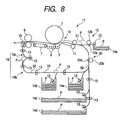
- a copier (both-face image forming apparatus) 30 for a first embodiment differs from the conventional copier 17 in that a recurling unit 32 for the second surface of a sheet is positioned on a sheet feeding path 50 extending between a photosensitive drum 1 and a sheet feeding deck 14b that is nearest a surface reversing unit (surface reversing means) 18.
- a sheet P other than a sheet P fed from the left deck 14b is fed by sheet feeding rollers 13 from sheet feed cassette 14e or one of the decks 14a, 14c and 14d, and is curled by initial curling units 33 and 34 for the first surface.
- the sheet is then fed to registration rollers 11, and an image is formed on the first surface of the sheet P.
- the surfaces of the sheet P are reversed and the sheet P is curled by a first R portion 18a and a second R portion 18b, and is then curled by the recurling unit 32 for the second surface and the initial curling unit 34 for the first surface. Thereafter, the curled sheet P is fed to the registration rollers 11, and an image is formed on the second surface by the photosensitive drum 1. The resultant sheet is thereafter conveyed to the outside and discharged.
- the curling distance provided by the recurling unit 32 for the second surface is defined as C (mm)
- the curling distance provided by the initial curling unit 33 for the first surface is defined as A (mm), and the curling distance provided by the first R portion 18a and the second R portion 18b of the surface reversing unit 18 is defined as B (mm).
- the recurling unit 32 includes a curling roller 32a made of iron and having a smaller diameter; a curling roller made of sponge and having a larger diameter larger than the curling roller 32a; and a spring 32c for pressing the sponge roller 32b against the iron roller 32a.
- the iron roller 32a is fixed to the main body of the apparatus.
- the curling roller 32a having a small diameter bites into the curling roller 32b having a large diameter. And as a sheet P passes the biting portion, the sheet P is pushed against and curled around the iron roller 32a.
- the diameters of the iron rollers 32a, 33a and 34a for the first and the second surfaces are approximately 8 mm, and the diameters of the sponge rollers 32b, 33b and 34b are approximately 20 mm.
- springs having a spring constant of about 0.135 N/mm are employed as the springs 33c and 34c for the curling rollers for the first surface, while a spring having a spring constant of about 0.196 N/mm is employed as the spring 32c for the roller for the second surface. Therefore, the force with which the curling rollers 33a and 34b for the first surface having small diameters bite into the curling rollers 33b and 34b for the first surface having large diameters is approximately 3 kg weight, and the force with which the curling roller 32a having a small diameter bites into the curling roller 32b for the second surface having a large diameter is approximately 39 N (4 kg weight).
- a curling distance of approximately 10 mm is applied to a sheet P by the initial curling units 33 and 34 for the first surface, and one of approximately 20 mm is applied to the sheet P by the recurling unit 32 for the second surface.
- the curling distance of a sheet P at the location whereat the sheet P separates from the photosensitive drum 1 is approximately 10 mm for the first surface, and is also approximately 10 mm in the effective separation direction for the second surface, so that the conveying of the sheet is very satisfactorily performed.
- the recurling unit 32 for the second surface be located upstream of the left deck 14b, i.e., on a reversed sheet conveying path 31 that connects the sheet feeding path 50 and the surface reversing means 18, as is shown in Fig. 3, and that in any case, a sheet P be prevented from passing through the recurling unit 32 for the second surface until image forming on the first surface of the sheet P has been completed.
- any type of sheet can be satisfactorily separated during the image forming performed for both the first surface and the second surface.
- the object of the present invention is attained by changing the spring constants of the springs 33c, 34c and 32c for the curling rollers.
- the object of the present invention can also be attained by setting the diameter of the iron roller 32a for the second surface so that it is smaller than the diameters of the iron rollers 33a and 34a for the first surface, or by setting the hardness of the sponge roller 32b for the second surface so that it is less than the hardness of the sponge roller 33b or 34b for the first surface.
- the rollers are so positioned that the depth to which the iron roller 32a for the second surface enters the sponge roller 32a is greater than the depth to which the iron rollers 33a and 34a for the first surface enter the sponge rollers 33b and 34b.
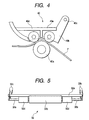
- Fig. 4 is a diagram showing a recurling unit 40, a modification of the recurling unit 32.
- the recurling unit 40 includes a lower roller 40a; a holder 40b, which rotates around a rotary shaft 40c and is urged toward the lower roller 40a; and two rollers 40d and 40e, which are mounted on the holder 40b.
- a sheet P is passed between the two rollers 40d and 40e and the lower roller 40a, which has entered the space between the rollers 40d and 40e, the sheet P is pushed against and curled around the lower roller 40a.
- the lower roller 40a has a jaw (not shown) of about 0.5 mm hight that increases its capability to discharge a sheet P.
- the initial curing units 33 and 34 may be arranged the same as the recurling unit 40 in Fig. 4. In this case, since the curling distance applied to a sheet by the recurling unit 40 must be greater than that applied by the initial curling units, the distance to which the lower roller of the recurling unit 40 advances into the space between the two upper rollers must be increased.
- the recurling unit 32 or 40 may be located on the sheet conveying path 52 upstream of the surface reversing means 18. In this case, the sheet is recurled by the recurling unit in the effective separation direction, but when the sheet passes through the surface reversing means 18, the sheet is again curled by the surface reversing means 18 and part of the recurling is canceled. However, since the curling applied to the sheet by the recurling unit 32 or 40 is more or less retained, no difficulty is encountered in separating from the photosensitive member 1 the sheet bearing an image on the second surface.
- the sheet conveying path 52 includes a conveying path, extending from the flapper 15 to the sheet feeding path 50 for the sheet feed deck 14b, that includes the surface reverse means 18 and the reversed sheet conveying path 31.
- the photosensitive drum 1 is employed as a photosensitive member.
- a flat photosensitive member is available, and the present invention can include either a drum type or a flat photosensitive member.
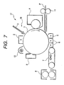
- the recurling unit 32 includes a curling roller 32a, which is an iron roller having a small diameter; a curling roller 32b, which is a sponge roller having a large diameter larger than that of the curling roller 32a; and a spring 32c for pressing the sponge roller 32b against the iron roller 32a.
- the iron roller 32a is fixed to the main body of the apparatus.
- the sponge roller 32b is shorter than the width of a sheet (approximately 300 mm) that passes through the rollers.
- a sheet approximately 300 mm
- the bending of the small iron roller 32a is reduced, and excessive curling at the ends of the sheet is prevented.
- collars 32d which have substantially the same diameter as has the sponge roller 32b when the iron roller 32a bites into the sponge roller 32b, are loosely fitted on a support shaft 32e of the sponge roller 32b at either end of the sponge roller 32.
- the arrangement of the initial curling unit 33 or 34 for the first surface is the same as that of the recurling unit 32 for the second surface, except for the portion explained below.
- the sponge rollers 33b and 34b for the first surface are shorter than the sponge roller 32b for the second surface (the end-cut lengths of the rollers 33b and 34b are longer than the end-cut length of the roller 32b).
- the lengths of the sponge rollers 33b and 34b for the first surface are approximately 200 mm (an end-cut length of about 100 mm), and the length of the sponge roller 32b for the second surface is approximately 240 mm (an end-cut length of about 60 mm).
- the diameter of the sponge roller 32b for the second surface is greater than the diameters of the sponge rollers 33b and 34b for the first surface, so that the curling distance applied by the recurling unit 32 for the second surface is greater than the curling distance applied by the initial curling units 33 and 34 for the first surface.
- the curling at the ends of the sheet tends to cause the formation of a blurred image or a blank area due to a poor transfer effect, more often than the curling in the intermediate portion of the sheet in the widthwise direction.
- the curling at the ends of the sheet can also furnish a starting point for the separation of the sheet from the photosensitive drum 1, and may promote separation.
- the ends of the sheet must be intentionally curled to cancel out the curling provided by the initial curling unit 33 or 34.
- the curling rollers 33b and 34b for the first surface are located closer to the photosensitive drum 1, blank areas due to poor transfer effects or blurred images tend to appear more frequently if the ends of sheets are curled too much.
- the curling distance at the ends of sheets must be reduced until it is less than that provided by the curling roller 32b for the second surface.
- the diameters of the iron rollers 32a, 33a and 34a for the first and the second surfaces are approximately 8 mm, and the diameters of the sponge rollers 32b, 33b and 34b are approximately 20 mm.
- springs having a spring constant of about 0.135 N/mm are employed as the springs 33c and 34c for the curling rollers for the first surface, while a spring having a spring constant of about 0.196 N/mm is employed as the spring 32c for the curling roller for the second surface. Therefore, the force with which the curling rollers 33a and 34b, which have a small diameter, bite into the curling rollers 33b and 34b having a large diameter for the first surface is approximately 3 kg weight, and the force with which the curling curling roller 32a, which has a small diameter, bites into the curling rollers 32b, which have a large diameter for the second surface, is approximately 39 N (4 kg weight).
- the curling distance for the first surface that is applied to the sheet P by the initial curling units 33 and 34 is approximately 10 mm
- for the curling distance applied by the recurling unit 32 for the second surface is approximately 20 mm.
- the length of the sponge roller 33b for the first surface is approximately 200 mm
- the length of each collar 33d located at either end of the roller 33b is about 50 mm
- the diameter of the collar 33d is about 6.5 mm.
- the length of the sponge roller 32b for the second surface is approximately 240 mm
- the length of each collar 32d located at either end of the roller 32b is about 30 mm
- the diameter of the collar 32d is about 6 mm.
- the curling distance of a sheet P at a location where it separates from the photosensitive drum 1 is approximately 10 mm for the first surface, and the curling distance for the second surface in the effective separation direction is also approximately 10 mm, so that the sheet is conveyed very satisfactorily.
- a blank area or a blurred image due to curling at the ends of a sheet P seldom occurs during the image forming process for the first surface and the second surface.
- the curling distance is also not the same as those described above, but is approximately 32 mm for the first surface and approximately -10 mm for the second surface.
- the recurling unit 32 for the second surface be located upstream of the left deck 14b, i.e., on a reversed sheet conveying path 31 that connects the sheet feeding path 50 and the surface reversing means 18, as is shown in Fig. 6, and that in any case, a sheet P be prevented from being passed through the recurling unit 32 until image forming on the first surface of the sheet P has been completed.
Landscapes
- Physics & Mathematics (AREA)
- General Physics & Mathematics (AREA)
- Separation, Sorting, Adjustment, Or Bending Of Sheets To Be Conveyed (AREA)
- Registering Or Overturning Sheets (AREA)
Claims (14)
- Doppelseitig arbeitendes Bilderzeugungsgerät, mit:dadurch gekennzeichnet, dasseiner Blattstapeleinrichtung (14a, 14b; 14c, 14d; 14e) zum Stapeln von Blättern;einer Bilderzeugungseinrichtung zur Erzeugung eines Bildes unter Verwendung eines lichtempfindlichen Elements (1) auf einem Blatt, das von der Blattstapeleinrichtung durch einen Blattzuführpfad (50; 51) geführt und gefördert ist;einer Vorkrümmungseinrichtung (33, 34), die in dem Blattzuführpfad angeordnet ist, um das Blatt in einer Richtung weg von dem lichtempfindlichen Element (1) zu krümmen, wenn das Blatt das lichtempfindliche Element passiert;einem Blattförderpfad (52), um das Blatt, auf dessen einer Oberfläche ein Bild durch die Bilderzeugungseinrichtung ausgebildet wurde, in den Blattzuführpfad zu führen;einer Wendeeinrichtung (18), die in dem Blattförderpfad angeordnet ist, um die Oberflächen des Blattes zu vertauschen; undeiner Nachkrümmungseinrichtung (32), die in dem Blattförderpfad angeordnet ist, um das Blatt in einer Richtung weg von dem lichtempfindlichen Element zu krümmen, wenn das Blatt nach dem Blattförderpfad das lichtempfindliche Element passiert,
ein Krümmungsvermögen der Nachkrümmungseinrichtung (32) größer ist als ein Krümmungsvermögen der Vorkrümmungseinrichtung (34, 33). - Doppelseitig arbeitendes Bilderzeugungsgerät nach Anspruch 1, wobei die Nachkrümmungseinrichtung (32) zwischen der Vorkrümmungseinrichtung (34, 33), die in dem Blattzuführpfad (50, 51) von der zur Wendeeinrichtung (18) nächsten Blattstapeleinrichtung (14b) angeordnet ist, und der Blattstapeleinrichtung (14b) angeordnet ist, die der Wendeeinrichtung (18) am nächsten ist.
- Doppelseitig arbeitendes Bilderzeugungsgerät nach Anspruch 1, wobei die Nachkrümmungseinrichtung (32) zwischen der Wendeeinrichtung (18) und der Blattstapeleinrichtung (14b) angeordnet ist, die der Oberflächenvertauschungseinrichtung am nächsten ist.
- Doppelseitig arbeitendes Bilderzeugungsgerät nach Anspruch 1, wobei sowohl die Vorkrümmungseinrichtung (34, 33) als auch die Nachkrümmungseinrichtung (32) eine Walze (34b, 33b) mit einem großen Durchmesser und eine Walze (34a, 33a) mit einem kleinen Durchmesser zum Einklemmen und Krümmen des Blatts hat, und wobei die Walze mit dem großen Durchmesser elastischer ist als die Walze mit dem kleinen Durchmesser.
- Doppelseitig arbeitendes Bilderzeugungsgerät nach Anspruch 4, wobei die Walze (43a, 33a) mit dem kleinen Durchmesser aus einem harten Metall gemacht ist und die Walze (34b, 33b) mit dem großen Durchmesser aus Schaumstoff gemacht ist.
- Doppelseitig arbeitendes Bilderzeugungsgerät nach Anspruch 4 oder 5, wobei eine Tiefe, bis zu der die Walze (32a) mit dem kleinen Durchmesser der Nachkrümmungseinrichtung (32) in die Walze (32b) mit dem großen Durchmesser eindringt, größer ist als eine Tiefe, bis zu der die Walze (34a, 33a) mit dem kleinen Durchmesser der Vorkrümmungseinrichtung (34, 33) in die Walze (34b, 33b) mit dem großen Durchmesser eindringt.
- Doppelseitig arbeitendes Bilderzeugungsgerät nach Anspruch 4 oder 5, wobei eine Kraft, mit der die Walze (32a) mit dem kleinen Durchmesser der Nachkrümmungseinrichtung (32) gegen die Walze (32b) mit dem großen·Durchmesser drückt, größer ist als eine Kraft, mit der die Walze (34a, 33a) mit dem kleinen Durchmesser der Vorkrümmungseinrichtung (34, 33) gegen die Walze (34b, 33b) mit dem großen Durchmesser drückt.
- Doppelseitig arbeitendes Bilderzeugungsgerät nach Anspruch 4 oder 5, wobei die Walze (32b) mit dem großen Durchmesser der Nachkrümmungseinrichtung (32) elastischer ist als die Walze (34b, 33b) mit dem großen Durchmesser der Vorkrümmungseinrichtung (34, 33).
- Doppelseitig arbeitendes Bilderzeugungsgerät nach Anspruch 4 oder 5, wobei ein Durchmesser der Walze (32a) mit dem kleinen Durchmesser der Nachkrümmungseinrichtung (32) kleiner ist als ein Durchmesser der Walze (34a, 33a) mit dem kleinen Durchmesser der Vorkrümmungseinrichtung (34, 33).
- Doppelseitig arbeitendes Bilderzeugungsgerät nach Anspruch 1, wobei sowohl die Vorkrümmungseinrichtung (34, 33) als auch die Nachkrümmungseinrichtung (32) ein Paar von Drückwalzen (40d, 40e), die getrennt voneinander in einer Blattförderrichtung angeordnet sind, und eine gedrückte Walze (40a) hat, die zwischen dem Paar von Drückwalzen angeordnet ist, um einen von den Drückwalzen aufgebrachten Druck aufzunehmen.
- Doppelseitig arbeitendes Bilderzeugungsgerät nach Anspruch 9, wobei eine Entfernung, bis zu der die gedrückte Walze (40a) der Nachkrümmungseinrichtung (32) in einen Raum zwischen dem Paar von Drückwalzen eintritt, größer ist als eine Entfernung, bis zu der die gedrückte Walze (40a) der Vorkrümmungseinrichtung (34, 33) in einen Raum zwischen dem Paar von Drückwalzen eintritt.
- Doppelseitig arbeitendes Bilderzeugungsgerät nach Anspruch 1, wobei sowohl die Vorkrümmungseinrichtung (34, 33) als auch die Nachkrümmungseinrichtung (32) eine Walze mit einem großen Durchmesser und eine Walze mit einem kleinen Durchmesser zum Einklemmen und Krümmen des Blatts hat, und wobei eine Länge der Walze (32b) mit dem großen Durchmesser der Nachkrümmungseinrichtung (32) kürzer ist als eine Breite des Blatts und größer ist als eine Länge der Walze (34b, 33b) mit dem großen Durchmesser der Vorkrümmungseinrichtung.
- Doppelseitig arbeitendes Bilderzeugungsgerät nach Anspruch 12, wobei an beiden Enden der Walze (32b) mit dem großen Durchmesser Haltewalzen (32d) vorgesehen sind, die die Walze (32a) mit dem kleinen Durchmesser berühren, wenn die Walze (32b) mit dem großen Durchmesser elastisch durch die Walze (32a) mit dem kleinen Durchmesser verformt ist, und wobei eine Gesamtlänge der Walze (32b) mit dem großen Durchmesser und den Haltewalzen (32d) sowie eine Länge der Walze (32a) mit dem kleinen Durchmesser größer oder gleich der Breite des Blatts sind.
- Doppelseitig arbeitendes Bilderzeugungsgerät nach Anspruch 11, wobei eine Länge des Paars von Drückwalzen (40d, 40e) der Nachkrümmungseinrichtung (32) kleiner ist als eine Breite des Blatts und größer ist als eine Länge des Paars von Drückwalzen (40d, 40e) der Vorkrümmungseinrichtung (34, 33).
Applications Claiming Priority (4)
| Application Number | Priority Date | Filing Date | Title |
|---|---|---|---|
| JP34624398 | 1998-12-04 | ||
| JP34624398A JP3957904B2 (ja) | 1998-12-04 | 1998-12-04 | 両面画像形成装置 |
| JP34624498 | 1998-12-04 | ||
| JP34624498A JP3969870B2 (ja) | 1998-12-04 | 1998-12-04 | 両面画像形成装置 |
Publications (3)
| Publication Number | Publication Date |
|---|---|
| EP1006417A2 EP1006417A2 (de) | 2000-06-07 |
| EP1006417A3 EP1006417A3 (de) | 2001-09-19 |
| EP1006417B1 true EP1006417B1 (de) | 2004-09-08 |
Family
ID=26578232
Family Applications (1)
| Application Number | Title | Priority Date | Filing Date |
|---|---|---|---|
| EP99124213A Expired - Lifetime EP1006417B1 (de) | 1998-12-04 | 1999-12-03 | Bilderzeugungsgerät |
Country Status (3)
| Country | Link |
|---|---|
| US (1) | US6415130B1 (de) |
| EP (1) | EP1006417B1 (de) |
| DE (1) | DE69919964T2 (de) |
Families Citing this family (13)
| Publication number | Priority date | Publication date | Assignee | Title |
|---|---|---|---|---|
| US6619657B2 (en) * | 2000-03-14 | 2003-09-16 | Canon Kabushiki Kaisha | Curl correction device, and image forming apparatus having the curl correction device |
| EP1288152B1 (de) * | 2001-08-31 | 2007-05-23 | Ricoh Company, Ltd. | Bogenauswerfeinrichtung, Vorrichtung zur Beseitigung von Blattwellungen und zur Bilderzeugung |
| US7690641B2 (en) * | 2007-06-04 | 2010-04-06 | Xerox Corporation | Gateless diverter—'S' shaped paper path |
| US20090154976A1 (en) * | 2007-12-13 | 2009-06-18 | Xerox Corporation | Method and apparatus for enhanced sheet hold down on an imaging transport |
| JP5203694B2 (ja) | 2007-12-28 | 2013-06-05 | ブラザー工業株式会社 | 画像処理装置、シート搬送装置 |
| US9139388B2 (en) * | 2009-09-11 | 2015-09-22 | Xerox Corporation | Side edge sheet curler for sheet hold down devices |
| JP5328693B2 (ja) * | 2010-02-26 | 2013-10-30 | キヤノン株式会社 | プリント装置およびシート処理装置 |
| US8538316B2 (en) * | 2010-02-26 | 2013-09-17 | Canon Kabushiki Kaisha | Printing apparatus and decurling device |
| JP2013088643A (ja) | 2011-10-19 | 2013-05-13 | Canon Inc | 画像形成装置 |
| JP2014028702A (ja) * | 2012-07-06 | 2014-02-13 | Ricoh Co Ltd | カール矯正装置、搬送装置及び画像形成装置 |
| JP6057753B2 (ja) * | 2013-02-07 | 2017-01-11 | キヤノン株式会社 | カール矯正装置及び画像形成装置 |
| JP6376775B2 (ja) | 2014-02-28 | 2018-08-22 | キヤノン株式会社 | シート搬送装置、シート切断装置、および画像形成装置 |
| JP2018115065A (ja) * | 2017-01-19 | 2018-07-26 | 株式会社東芝 | 画像形成装置 |
Family Cites Families (7)
| Publication number | Priority date | Publication date | Assignee | Title |
|---|---|---|---|---|
| JPS60213979A (ja) * | 1984-04-10 | 1985-10-26 | Matsushita Electric Ind Co Ltd | クリ−ニング装置 |
| JP2702598B2 (ja) * | 1990-09-28 | 1998-01-21 | シャープ株式会社 | 電子写真装置 |
| US5572308A (en) * | 1994-03-24 | 1996-11-05 | Canon Kabushiki Kaisha | Image forming apparatus with curl forming means |
| JPH0925041A (ja) * | 1995-07-07 | 1997-01-28 | Canon Inc | 画像形成装置 |
| JPH09150984A (ja) * | 1995-11-27 | 1997-06-10 | Eastman Kodak Japan Kk | 用紙搬送装置 |
| JP3268727B2 (ja) * | 1996-05-16 | 2002-03-25 | キヤノン株式会社 | 画像形成装置 |
| JPH1017197A (ja) * | 1996-07-03 | 1998-01-20 | Canon Inc | シート搬送装置及び画像形成装置 |
-
1999
- 1999-12-03 EP EP99124213A patent/EP1006417B1/de not_active Expired - Lifetime
- 1999-12-03 US US09/453,691 patent/US6415130B1/en not_active Expired - Fee Related
- 1999-12-03 DE DE69919964T patent/DE69919964T2/de not_active Expired - Lifetime
Also Published As
| Publication number | Publication date |
|---|---|
| DE69919964D1 (de) | 2004-10-14 |
| EP1006417A3 (de) | 2001-09-19 |
| US6415130B1 (en) | 2002-07-02 |
| EP1006417A2 (de) | 2000-06-07 |
| DE69919964T2 (de) | 2005-09-15 |
Similar Documents
| Publication | Publication Date | Title |
|---|---|---|
| JP4038328B2 (ja) | 画像形成装置、転写材搬送方法及び転写装置 | |
| EP1006417B1 (de) | Bilderzeugungsgerät | |
| US5515152A (en) | Multi-gate tandem decurler | |
| JPH08127456A (ja) | シートのクロス方向カールを減少するカール除去装置 | |
| US6595512B2 (en) | Constant force sheet feeder | |
| US5740512A (en) | Image formation system with swell correction | |
| JP3957904B2 (ja) | 両面画像形成装置 | |
| JP2001192161A (ja) | 画像形成装置 | |
| JP3969870B2 (ja) | 両面画像形成装置 | |
| JP2002174966A (ja) | 画像形成装置 | |
| US6438333B1 (en) | Image forming apparatus with reduced transfer current to transfer material rear end | |
| JPH1165192A (ja) | 排紙装置 | |
| JP2991474B2 (ja) | 画像形成装置 | |
| JP4244711B2 (ja) | 画像形成装置 | |
| JPH09146384A (ja) | 転写装置 | |
| JP2004212755A (ja) | 画像形成装置 | |
| JPH10231061A (ja) | 画像形成装置のカール矯正装置 | |
| JPH08310704A (ja) | 紙葉搬送装置 | |
| JP4207673B2 (ja) | 画像形成装置 | |
| JPH0326630A (ja) | 電子写真装置の記録用紙搬送装置 | |
| JP2675880B2 (ja) | 画像形成装置 | |
| JPH09297469A (ja) | 画像形成装置 | |
| JP2024119740A (ja) | 画像形成システム及び除電装置 | |
| JP2002193514A (ja) | 排紙装置および画像形成装置 | |
| JPH0617132Y2 (ja) | 画像形成装置 |
Legal Events
| Date | Code | Title | Description |
|---|---|---|---|
| PUAI | Public reference made under article 153(3) epc to a published international application that has entered the european phase |
Free format text: ORIGINAL CODE: 0009012 |
|
| AK | Designated contracting states |
Kind code of ref document: A2 Designated state(s): AT BE CH CY DE DK ES FI FR GB GR IE IT LI LU MC NL PT SE Kind code of ref document: A2 Designated state(s): DE FR GB IT |
|
| AX | Request for extension of the european patent |
Free format text: AL;LT;LV;MK;RO;SI |
|
| PUAL | Search report despatched |
Free format text: ORIGINAL CODE: 0009013 |
|
| AK | Designated contracting states |
Kind code of ref document: A3 Designated state(s): AT BE CH CY DE DK ES FI FR GB GR IE IT LI LU MC NL PT SE |
|
| AX | Request for extension of the european patent |
Free format text: AL;LT;LV;MK;RO;SI |
|
| 17P | Request for examination filed |
Effective date: 20020201 |
|
| 17Q | First examination report despatched |
Effective date: 20020417 |
|
| AKX | Designation fees paid |
Free format text: DE FR GB IT |
|
| GRAP | Despatch of communication of intention to grant a patent |
Free format text: ORIGINAL CODE: EPIDOSNIGR1 |
|
| GRAS | Grant fee paid |
Free format text: ORIGINAL CODE: EPIDOSNIGR3 |
|
| GRAA | (expected) grant |
Free format text: ORIGINAL CODE: 0009210 |
|
| AK | Designated contracting states |
Kind code of ref document: B1 Designated state(s): DE FR GB IT |
|
| PG25 | Lapsed in a contracting state [announced via postgrant information from national office to epo] |
Ref country code: IT Free format text: LAPSE BECAUSE OF FAILURE TO SUBMIT A TRANSLATION OF THE DESCRIPTION OR TO PAY THE FEE WITHIN THE PRESCRIBED TIME-LIMIT;WARNING: LAPSES OF ITALIAN PATENTS WITH EFFECTIVE DATE BEFORE 2007 MAY HAVE OCCURRED AT ANY TIME BEFORE 2007. THE CORRECT EFFECTIVE DATE MAY BE DIFFERENT FROM THE ONE RECORDED. Effective date: 20040908 |
|
| REG | Reference to a national code |
Ref country code: GB Ref legal event code: FG4D |
|
| REF | Corresponds to: |
Ref document number: 69919964 Country of ref document: DE Date of ref document: 20041014 Kind code of ref document: P |
|
| PLBE | No opposition filed within time limit |
Free format text: ORIGINAL CODE: 0009261 |
|
| STAA | Information on the status of an ep patent application or granted ep patent |
Free format text: STATUS: NO OPPOSITION FILED WITHIN TIME LIMIT |
|
| ET | Fr: translation filed | ||
| 26N | No opposition filed |
Effective date: 20050609 |
|
| PGFP | Annual fee paid to national office [announced via postgrant information from national office to epo] |
Ref country code: DE Payment date: 20131231 Year of fee payment: 15 Ref country code: GB Payment date: 20131217 Year of fee payment: 15 |
|
| PGFP | Annual fee paid to national office [announced via postgrant information from national office to epo] |
Ref country code: FR Payment date: 20131227 Year of fee payment: 15 |
|
| REG | Reference to a national code |
Ref country code: DE Ref legal event code: R119 Ref document number: 69919964 Country of ref document: DE |
|
| GBPC | Gb: european patent ceased through non-payment of renewal fee |
Effective date: 20141203 |
|
| REG | Reference to a national code |
Ref country code: FR Ref legal event code: ST Effective date: 20150831 |
|
| PG25 | Lapsed in a contracting state [announced via postgrant information from national office to epo] |
Ref country code: GB Free format text: LAPSE BECAUSE OF NON-PAYMENT OF DUE FEES Effective date: 20141203 Ref country code: DE Free format text: LAPSE BECAUSE OF NON-PAYMENT OF DUE FEES Effective date: 20150701 |
|
| PG25 | Lapsed in a contracting state [announced via postgrant information from national office to epo] |
Ref country code: FR Free format text: LAPSE BECAUSE OF NON-PAYMENT OF DUE FEES Effective date: 20141231 |