EP0991342B1 - Sitz - Google Patents
Sitz Download PDFInfo
- Publication number
- EP0991342B1 EP0991342B1 EP98938624A EP98938624A EP0991342B1 EP 0991342 B1 EP0991342 B1 EP 0991342B1 EP 98938624 A EP98938624 A EP 98938624A EP 98938624 A EP98938624 A EP 98938624A EP 0991342 B1 EP0991342 B1 EP 0991342B1
- Authority
- EP
- European Patent Office
- Prior art keywords
- seat
- adjusting
- cushion
- adjusting elements
- elements
- Prior art date
- Legal status (The legal status is an assumption and is not a legal conclusion. Google has not performed a legal analysis and makes no representation as to the accuracy of the status listed.)
- Expired - Lifetime
Links
- 230000033001 locomotion Effects 0.000 claims description 36
- 239000007788 liquid Substances 0.000 claims description 23
- 210000004197 pelvis Anatomy 0.000 claims description 11
- 238000000034 method Methods 0.000 claims description 9
- 230000002441 reversible effect Effects 0.000 claims description 2
- 238000005192 partition Methods 0.000 claims 1
- 239000000463 material Substances 0.000 description 7
- 238000005086 pumping Methods 0.000 description 6
- 238000005259 measurement Methods 0.000 description 5
- 238000012546 transfer Methods 0.000 description 5
- 230000005540 biological transmission Effects 0.000 description 4
- 230000001105 regulatory effect Effects 0.000 description 4
- 238000010276 construction Methods 0.000 description 3
- 238000010586 diagram Methods 0.000 description 3
- 230000000694 effects Effects 0.000 description 3
- 239000012530 fluid Substances 0.000 description 3
- 238000004519 manufacturing process Methods 0.000 description 3
- 230000009471 action Effects 0.000 description 2
- 238000013459 approach Methods 0.000 description 2
- 230000008901 benefit Effects 0.000 description 2
- 230000037396 body weight Effects 0.000 description 2
- 230000008859 change Effects 0.000 description 2
- 230000001276 controlling effect Effects 0.000 description 2
- 239000013013 elastic material Substances 0.000 description 2
- 239000004744 fabric Substances 0.000 description 2
- 238000009434 installation Methods 0.000 description 2
- 230000003068 static effect Effects 0.000 description 2
- 239000000725 suspension Substances 0.000 description 2
- 230000006978 adaptation Effects 0.000 description 1
- 230000000712 assembly Effects 0.000 description 1
- 238000000429 assembly Methods 0.000 description 1
- 239000011324 bead Substances 0.000 description 1
- 230000000903 blocking effect Effects 0.000 description 1
- 210000001217 buttock Anatomy 0.000 description 1
- 230000001419 dependent effect Effects 0.000 description 1
- 238000013461 design Methods 0.000 description 1
- 238000011161 development Methods 0.000 description 1
- 238000009826 distribution Methods 0.000 description 1
- 230000000977 initiatory effect Effects 0.000 description 1
- 230000002045 lasting effect Effects 0.000 description 1
- 235000015097 nutrients Nutrition 0.000 description 1
- 230000000399 orthopedic effect Effects 0.000 description 1
- 230000008569 process Effects 0.000 description 1
- 230000002035 prolonged effect Effects 0.000 description 1
- 230000010349 pulsation Effects 0.000 description 1
- 230000009467 reduction Effects 0.000 description 1
- 238000005096 rolling process Methods 0.000 description 1
- 239000007787 solid Substances 0.000 description 1
- 230000001360 synchronised effect Effects 0.000 description 1
- 230000007704 transition Effects 0.000 description 1
- 230000036642 wellbeing Effects 0.000 description 1
Images


Classifications
-
- B—PERFORMING OPERATIONS; TRANSPORTING
- B60—VEHICLES IN GENERAL
- B60N—SEATS SPECIALLY ADAPTED FOR VEHICLES; VEHICLE PASSENGER ACCOMMODATION NOT OTHERWISE PROVIDED FOR
- B60N2/00—Seats specially adapted for vehicles; Arrangement or mounting of seats in vehicles
- B60N2/02—Seats specially adapted for vehicles; Arrangement or mounting of seats in vehicles the seat or part thereof being movable, e.g. adjustable
- B60N2/04—Seats specially adapted for vehicles; Arrangement or mounting of seats in vehicles the seat or part thereof being movable, e.g. adjustable the whole seat being movable
- B60N2/16—Seats specially adapted for vehicles; Arrangement or mounting of seats in vehicles the seat or part thereof being movable, e.g. adjustable the whole seat being movable height-adjustable
- B60N2/18—Seats specially adapted for vehicles; Arrangement or mounting of seats in vehicles the seat or part thereof being movable, e.g. adjustable the whole seat being movable height-adjustable the front or the rear portion of the seat being adjustable, e.g. independently of each other
- B60N2/1807—Seats specially adapted for vehicles; Arrangement or mounting of seats in vehicles the seat or part thereof being movable, e.g. adjustable the whole seat being movable height-adjustable the front or the rear portion of the seat being adjustable, e.g. independently of each other characterised by the cinematic
- B60N2/181—Rods
-
- A—HUMAN NECESSITIES
- A47—FURNITURE; DOMESTIC ARTICLES OR APPLIANCES; COFFEE MILLS; SPICE MILLS; SUCTION CLEANERS IN GENERAL
- A47C—CHAIRS; SOFAS; BEDS
- A47C7/00—Parts, details, or accessories of chairs or stools
- A47C7/02—Seat parts
- A47C7/14—Seat parts of adjustable shape; elastically mounted ; adaptable to a user contour or ergonomic seating positions
-
- A—HUMAN NECESSITIES
- A47—FURNITURE; DOMESTIC ARTICLES OR APPLIANCES; COFFEE MILLS; SPICE MILLS; SUCTION CLEANERS IN GENERAL
- A47C—CHAIRS; SOFAS; BEDS
- A47C9/00—Stools for specified purposes
- A47C9/002—Stools for specified purposes with exercising means or having special therapeutic or ergonomic effects
-
- B—PERFORMING OPERATIONS; TRANSPORTING
- B60—VEHICLES IN GENERAL
- B60N—SEATS SPECIALLY ADAPTED FOR VEHICLES; VEHICLE PASSENGER ACCOMMODATION NOT OTHERWISE PROVIDED FOR
- B60N2/00—Seats specially adapted for vehicles; Arrangement or mounting of seats in vehicles
- B60N2/02—Seats specially adapted for vehicles; Arrangement or mounting of seats in vehicles the seat or part thereof being movable, e.g. adjustable
- B60N2/04—Seats specially adapted for vehicles; Arrangement or mounting of seats in vehicles the seat or part thereof being movable, e.g. adjustable the whole seat being movable
- B60N2/10—Seats specially adapted for vehicles; Arrangement or mounting of seats in vehicles the seat or part thereof being movable, e.g. adjustable the whole seat being movable tiltable
-
- B—PERFORMING OPERATIONS; TRANSPORTING
- B60—VEHICLES IN GENERAL
- B60N—SEATS SPECIALLY ADAPTED FOR VEHICLES; VEHICLE PASSENGER ACCOMMODATION NOT OTHERWISE PROVIDED FOR
- B60N2/00—Seats specially adapted for vehicles; Arrangement or mounting of seats in vehicles
- B60N2/02—Seats specially adapted for vehicles; Arrangement or mounting of seats in vehicles the seat or part thereof being movable, e.g. adjustable
- B60N2/04—Seats specially adapted for vehicles; Arrangement or mounting of seats in vehicles the seat or part thereof being movable, e.g. adjustable the whole seat being movable
- B60N2/16—Seats specially adapted for vehicles; Arrangement or mounting of seats in vehicles the seat or part thereof being movable, e.g. adjustable the whole seat being movable height-adjustable
- B60N2/18—Seats specially adapted for vehicles; Arrangement or mounting of seats in vehicles the seat or part thereof being movable, e.g. adjustable the whole seat being movable height-adjustable the front or the rear portion of the seat being adjustable, e.g. independently of each other
- B60N2/185—Seats specially adapted for vehicles; Arrangement or mounting of seats in vehicles the seat or part thereof being movable, e.g. adjustable the whole seat being movable height-adjustable the front or the rear portion of the seat being adjustable, e.g. independently of each other characterised by the drive mechanism
- B60N2/1853—Linear actuator, e.g. screw mechanism
-
- B—PERFORMING OPERATIONS; TRANSPORTING
- B60—VEHICLES IN GENERAL
- B60N—SEATS SPECIALLY ADAPTED FOR VEHICLES; VEHICLE PASSENGER ACCOMMODATION NOT OTHERWISE PROVIDED FOR
- B60N2/00—Seats specially adapted for vehicles; Arrangement or mounting of seats in vehicles
- B60N2/02—Seats specially adapted for vehicles; Arrangement or mounting of seats in vehicles the seat or part thereof being movable, e.g. adjustable
- B60N2/04—Seats specially adapted for vehicles; Arrangement or mounting of seats in vehicles the seat or part thereof being movable, e.g. adjustable the whole seat being movable
- B60N2/16—Seats specially adapted for vehicles; Arrangement or mounting of seats in vehicles the seat or part thereof being movable, e.g. adjustable the whole seat being movable height-adjustable
- B60N2/18—Seats specially adapted for vehicles; Arrangement or mounting of seats in vehicles the seat or part thereof being movable, e.g. adjustable the whole seat being movable height-adjustable the front or the rear portion of the seat being adjustable, e.g. independently of each other
- B60N2/185—Seats specially adapted for vehicles; Arrangement or mounting of seats in vehicles the seat or part thereof being movable, e.g. adjustable the whole seat being movable height-adjustable the front or the rear portion of the seat being adjustable, e.g. independently of each other characterised by the drive mechanism
- B60N2/1878—Hydraulic or pneumatic actuation
-
- B—PERFORMING OPERATIONS; TRANSPORTING
- B60—VEHICLES IN GENERAL
- B60R—VEHICLES, VEHICLE FITTINGS, OR VEHICLE PARTS, NOT OTHERWISE PROVIDED FOR
- B60R16/00—Electric or fluid circuits specially adapted for vehicles and not otherwise provided for; Arrangement of elements of electric or fluid circuits specially adapted for vehicles and not otherwise provided for
- B60R16/08—Electric or fluid circuits specially adapted for vehicles and not otherwise provided for; Arrangement of elements of electric or fluid circuits specially adapted for vehicles and not otherwise provided for fluid
-
- F—MECHANICAL ENGINEERING; LIGHTING; HEATING; WEAPONS; BLASTING
- F15—FLUID-PRESSURE ACTUATORS; HYDRAULICS OR PNEUMATICS IN GENERAL
- F15B—SYSTEMS ACTING BY MEANS OF FLUIDS IN GENERAL; FLUID-PRESSURE ACTUATORS, e.g. SERVOMOTORS; DETAILS OF FLUID-PRESSURE SYSTEMS, NOT OTHERWISE PROVIDED FOR
- F15B11/00—Servomotor systems without provision for follow-up action; Circuits therefor
- F15B11/16—Servomotor systems without provision for follow-up action; Circuits therefor with two or more servomotors
- F15B11/20—Servomotor systems without provision for follow-up action; Circuits therefor with two or more servomotors controlling several interacting or sequentially-operating members
-
- F—MECHANICAL ENGINEERING; LIGHTING; HEATING; WEAPONS; BLASTING
- F15—FLUID-PRESSURE ACTUATORS; HYDRAULICS OR PNEUMATICS IN GENERAL
- F15B—SYSTEMS ACTING BY MEANS OF FLUIDS IN GENERAL; FLUID-PRESSURE ACTUATORS, e.g. SERVOMOTORS; DETAILS OF FLUID-PRESSURE SYSTEMS, NOT OTHERWISE PROVIDED FOR
- F15B15/00—Fluid-actuated devices for displacing a member from one position to another; Gearing associated therewith
- F15B15/08—Characterised by the construction of the motor unit
- F15B15/10—Characterised by the construction of the motor unit the motor being of diaphragm type
- F15B15/103—Characterised by the construction of the motor unit the motor being of diaphragm type using inflatable bodies that contract when fluid pressure is applied, e.g. pneumatic artificial muscles or McKibben-type actuators
Definitions
- the invention relates to a seat according to the preamble of claims 1 and 20 and a method for controlling a seat according to the preamble of claims 21 and 22.
- All types of seating elements with a Referred to as a seat cushion and possibly a backrest for example office chairs, Bicycle saddles, seats in motor vehicles, etc.
- the object of the invention is to show ways to the described tilting movement to produce seats, in particular vehicle seats.
- the seat cushion there is at least one pair of adjusting elements in the area of the seat cushion intended.
- These two control elements are located opposite each other Arrange areas of the seat cushion and control it so that it is a perform the opposite stroke movement between a lower and an upper position.
- the opposite upward and downward movement becomes a tilting movement reached about a longitudinal or transverse axis of the seat. It is about make sure that the tilt axis is as close as possible to the buttocks of the on the Seat cushion seated person lies. Due to the control elements only a pure tilting movement be generated; an up and down movement of the seated person, which would have a lasting impact on well-being is imperative to avoid.
- Claims 2 to 4 show different possibilities for the arrangement of the adjusting elements.
- the entire seat is tilted, which can be implemented especially with seat constructions with a rigid seat shell.
- the adjusting elements are arranged between the support structure and the cushion part.
- the support structure can in turn be spring-loaded. If the adjusting elements are arranged directly in the upholstery part (claim 4), only minor changes to the supporting structure of the seat are required. Due to the small distance between the adjusting elements and the seat bumps of the seated person, the tilting movement is transmitted directly.
- the control elements can also be arranged in a direct line below the ischial humps.
- Adjusting elements according to claim 5 are particularly simple in construction and adaptation to the respective application. They are also inexpensive to manufacture.
- elements with flexible walls come as control elements in question, e.g. B. bubbles or bellows made of a rubber-elastic material. Due to the relatively large weight forces exerted by the seated person it is advisable to reinforce the bladders, bellows, etc. with a fabric insert.
- Bellows are particularly suitable because they have flat, have rigid limits for connection to the seat structure. Same effect Short-stroke cylinders with rigid can also be used for the above-mentioned control elements Chamber wall can be used.
- Such cylinders are characterized by a accordingly large diameter with a small adjustment path and stress thus an installation space that essentially takes up the space required for bellows-type control elements corresponds.
- the actuating elements according to claim 5 can be operated with air or with a liquid.
- Air-filled adjusting elements are particularly suitable for an arrangement in the upholstered part of the seat cushion, since they adapt to the shape of the seat bumps and do not give the impression of a hard insert. Because of the pressure and temperature dependence of the air volume in the control elements, however, suitable measures for regulating the adjustment path of the control elements are required, for example by means of distance measurement on the control elements.
- the control elements are operated with a liquid medium, a defined and reproducible control path can be realized due to the incompressibility of the liquid, so that the control or regulation of the control path can be carried out via a simple measurement of the volume flow to and from the control element. Due to the intransigence of liquid-filled actuating elements, however, an arrangement directly in the upholstery near the seat bumps of a seated person is only possible with restrictions.
- the medium for the control elements in separate working chambers provided. With the transfer of the medium from the first working chamber the medium from the other is simultaneously in the associated control element Pulled actuator in the second working chamber, so that the invention Push-pull sets automatically.
- the emptying of the control element which is in its elevated position is determined by the weight of the seated Person supports.
- the working chambers as well as the drive for the volume shift can advantageously outside the immediate seating area be arranged so that only one within the seat or the seat cushion little space is required.
- the tilting movement for example, by a double-acting pneumatic or hydraulic cylinders can be realized.
- a liquid working medium can be defined and measured by measuring the piston stroke reproducible working stroke of the control elements can be achieved.
- Working chambers formed can also be bellows-shaped working chambers (Claim 8) may be provided.
- a piston pump can also be used instead of a rotary vane pump be, which are also measurable when using a liquid medium Volume flow promotes.
- the application is due to the pulsations that occur of piston pumps limited to smaller individual volumes. Where applicable Use multi-piston pumps.
- Elements with flexible walls are preferred as adjusting elements, e.g. B. bubbles or bellows made of a rubber-elastic material. Because of the relative large acting weight forces by the seated person it is recommended reinforce the bladders, bellows, etc. with a fabric insert. Using bubble-like control elements result in a very small space requirement, since the overall height the control elements in the initial state only by the sum of their Wall thickness is determined.
- Rolled bellows are also particularly suitable because they have flat, rigid boundaries on the top and bottom for connection to the Have seat structure. Can have the same effect on the control elements mentioned short-stroke cylinders with rigid chamber walls can also be used.
- Such Cylinders are characterized by a correspondingly large diameter with a small one Adjustment path and thus take up an installation space that is essentially corresponds to the space required for bellows-type control elements.
- Adjustment heights With two control elements arranged one above the other, there are three defined ones Adjustment heights:
- the depressurized state of both control elements marks the lower position, whose overall height, for example, in the case of bubble-like control elements, is achieved solely by Sum of the wall thicknesses of the two bubbles is determined.
- a middle position results from pressurization of one of the two control elements while the second control element remains depressurized.
- the top position can go through Pressurization of both control elements can be started in a defined manner. Become the two control elements are designed in the same way, a middle position can be reached be exactly in the geometric center between the lower and upper position lies.
- Adjustment elements in the two seat cushion areas will tilt the Achieves pelvis about the longitudinal or transverse axis of the seat, as described in claim 22.
- the claimed control includes the same also embodiments with more than two arranged one above the other Control elements.
- Pneumatic control elements are generally of a simpler structure and easier to control than liquid-filled actuators. Because of the compressibility of the gaseous medium and its strong temperature dependence however, the (maximum) travel is not reproducible. Therefore, according to claim 12 proposed by an additional device on the actuator Limit the adjustment path automatically. Thus, regardless of the load of the pneumatic control element, each with a defined maximum travel range complied with, provided that the actuating element is subjected to an internal pressure which is larger than it is due to the effective inner surface of the actuator and would be necessary for a seated person. This ensures that without additional measures, such as a distance measurement, a constant adjustment path is maintained.
- path limits are provided in the interior of the actuating element. These path limitations preferably consist of a flexible, not stretchy material. You can use control elements with walls made of one Plastic material welded directly to the actuator during manufacture become. This results in a particularly simple structure and an inexpensive one Manufacturing.
- the wall sections - viewed in the adjustment direction - can be opposite with control elements made of a plastic material in sections with each other are welded so that there is also a through these welds Path limitation results (comparable to the stitching, for example with air mattresses).
- Path limitation results (comparable to the stitching, for example with air mattresses).
- the partially or circumferentially annular wrapping of the actuating element for example, with tapes made of flexible and non-stretch material he follows.
- the path limitation on the outer circumference of the actuating element is preferred additionally fixed to reliably prevent the actuator from slipping when depressurized to prevent.
- the two seat halves provided a shut-off valve be reliable, through which an exchange of the medium between the control elements is prevented.
- the shut-off valve is activated by the user, if the device for generating a tilting movement is switched off and that Seat cushions should be fixed in an "oblique" position by using the adjusting elements in different height positions can be “locked”.
- the shut-off valve turns on slow overflow of the medium, e.g. B. due to leakage in a pump, prevented.
- Such an application is considered, for example, for seat users, who, for orthopedic reasons, need to tilt the seat cushion.
- Claims 15 to 19 show examples of further basic principles of action of control elements.
- the principles of action mentioned can be achieved by a motor Actuator, for example an electric motor or with one Pressure media are implemented. Electric motors in particular are characterized by small space requirement and their easy controllability.
- the motor Actuators can be combined with all known transmission elements, for example with rotary or linear gears, eccentrics, racks, etc. With pressure medium drive due to the better control options and the higher working pressures preferred hydraulic media.
- Spindle drives according to claim 16 are driven by a rotary motor and convert its rotational movement into a vertical movement. Is preferred to provide a common drive shaft for the adjusting elements arranged in pairs. This applies analogously to eccentric drives according to claim 17 and Lifting linkage according to claim 18.
- wedge-shaped elements in particular wedge-shaped disks, the can be rotated against each other, height changes in the area of the seat bumps the seated person can be reached.
- the wedge disks can be used Reduction of the friction on rolling elements against each other.
- the tilt of the seat cushion by a one-sided attack Control element realized.
- This tilt is particularly useful for such seats, the seat cushion of which has a rigid "seat pan", as a whole is tiltable about a predetermined central axis.
- Tilting over one sided Attacking actuator can also be found in seats with a spring core substructure apply, in which case a tilt axis automatically in the middle of the seat cushion.
- the actuator is preferably outside of the Support structure of the seat cushion arranged. Also an arrangement of the control element between the supporting structure and the upholstered part is possible.
- control elements come for example basically all the above-mentioned embodiments in question.
- Claim 21 describes a method with which, regardless of the seat position or the body weight of the seat user, a constant central position for a bubble-like adjusting element (according to claim 5) can be achieved.
- Certain types of pumps e.g. rotary vane pumps
- the fluid flow delivered is, however, dependent on various parameters, e.g. B. Drive direction of the pump, pumping or suction operation, level of pressure against which the pumping or suction is carried out, etc.
- N12 and N21 indicate how many pulses each for the complete pumping the liquid between the two control elements are required.
- the Dimensional figures N12 and N21 are calculated with previously empirically determined factors F12 and F21 multiplied.
- the factors F12 and F21 are executed for a particular one Consistent unit of seat and control elements. Since the factors F12 and F21 in usually differ only slightly from each other, can be for the two pump directions to simplify work with a uniform factor F.
- the seat load is largely determined by the body weight of the seat user and the Contact area between the seat user and the seat cushion determined. Besides The seating position of the seat user also influences the values N12 and N21, depending on whether the right or left or the front or rear half of the seat is heavier become.
- the system thus arises according to the method according to the invention not only to different seat users, but also dynamically changing seating positions of the same seat user.
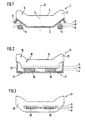
- Fig. 1 shows a seat cushion 1, which consists of a support structure 2 and a cushion part 3 composed.
- the middle part of the seat cushion 1 is designed as a seat surface 4, while the lateral areas 5 are designed in a wuist shape.
- At the bottom of the Support structure 2 attack on the right and left outside actuating elements 6, respectively take a middle layer M as well as an upper and a lower position O and U respectively can.
- a seat suspension is resilient within certain limits (Suspension 8), when the right and left move in opposite directions Adjusting elements 6 generates a tilting movement of the seat cushion about a tilting axis 7, which lies in the longitudinal center plane 9 of the seat cushion 1.
- Fig. 2 shows a seat cushion 11, in which the adjusting elements 16 between the Support structure 12 and the cushion part 13 are arranged. Above all, they are suitable for this flat actuators 16.
- the individual positions that the actuators 16 can take, are again designated M, O and U. Transition areas 18 between the beads rigidly connected to the support structure 12 15 and the seat surface 14 allow compensation by the adjusting elements 16 caused tilting movements.
- the support structure 12 can in turn be sprung be, as illustrated in FIG. 2 by means of the springs 17 shown in broken lines.
- FIG. 3 shows a further possibility of introducing adjusting elements 26 into a Seat cushion 21, which in turn consists of a support structure (not shown) and a cushion part 23 is composed.
- the adjusting elements 26 are preferably air-filled Bubbles or low-profile roll bellows executed. You can in the upholstered part inserted or glued or also foamed by the material of the cushion part 23 his.
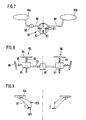
- 4 to 7 show different ways of driving actuating elements via a liquid or gaseous medium.
- a double-acting cylinder 40 is shown, the connecting lines 41 controls 46a and 46b.
- the cylinder has a first and a second working chamber 42 and 43, which are separated by a piston 44 are separated.
- the piston can be moved via a piston rod 45, the volumes of the two working chambers 42 and 43 in opposite directions Wise enlarge or reduce.
- a second piston rod 47 provides the same volume in the two working chambers 42 and 43 safely.
- the actuator 46a is formed as a bubble-shaped structure with walls 48 that are flexible on all sides, while the actuator 46b of a bellows-like structure with an upper and a lower cover plate 49 or 50 and a rubber-elastic bellows 51 is formed.
- the working chambers 62 and 63 are in one housing 60 recorded and are formed by bladders or bellows that over Connecting lines 61 are connected to control elements, not shown.
- the housing 60 guides a slide 64, which is parallel to the lateral boundary walls 65 of the housing 60 can be moved (path s).
- the two working chambers 72 and 73 arranged in a housing 70 which is approximately V-shaped in cross section.
- a Swivel plate 74 is at the intersection of the two boundary walls 75 of the Housing 70 pivotally mounted (pivot axis 71), so that the plate 74 at a force introduction z. B. at the point of application 77 or torque initiation the pivot axis 71 can be adjusted (pivot angle ⁇ ).
- the adjusting elements according to FIGS. 4 to 6 are via separate fluid circuits adjusted in opposite directions.
- the adjustment can be made, for example, via a reciprocating linear drive, an eccentric drive, etc. take place.
- liquid media become almost constant travel ranges regardless of load reached on the control elements.
- a reservoir Working chambers 42, 43 or 62, 63 or 72, 73
- Control elements are filled or emptied.
- the adjusting elements 86a and 86b according to FIG. 7 are via a Rotary vane pump 80 directly connected to each other and become in opposite directions pressurized.
- the rotary vane pump 80 has a plurality of chambers 81, which promote a defined chamber volume.
- the individual chambers 81 are over radially movable slide 82 separated from each other and opposite the pump housing 83 sealed.
- the arrangement shown in FIG. 7 allows separate Chambers for providing the working medium are dispensed with, whereby a particularly compact design results.
- the rotary vane pump 80 can for example driven by an electric motor, the speed of which is about a Hall sensor is detected, so that when moving liquid media the travel the actuating elements 86a and 86b can be controlled or regulated in a simple manner can.
- shutt-off valve 89 is provided, with which an exchange of the medium between the two control elements 86a and 86b can be prevented to a static To achieve "misalignment" of the seat cushion of the vehicle seat.
- the misalignment is achieved, for example, in that the blocking in the de-energized state Valve 89 is energized briefly, so that the leakage gap of the rotary vane pump 80 under the weight and possibly a consciously influenced weight distribution a leakage current flows from the seat user and the desired one Skew.
- FIG. 8 shows adjusting elements 96, each of which has a spindle nut 91 and a spindle 92 exhibit. Both actuating elements 96 are driven by a drive shaft 93 Electric motor 90 driven.
- the spindle nuts 91 set the rotational movement the shaft 93 in a vertical movement of the plate-shaped transmission elements 94 um.
- the spindle nuts 91 are via springs 95 in relation to the seat structure 98 supported.
- the pairings "spindle nut 91 - spindle 92" have one half of the seat cushion a right-hand or left-hand thread to turn the shaft 93 to achieve an opposite movement of the two transfer plates 94.
- Fig. 9 shows lever assemblies 101, with which a direct introduction of force on transmission plates 104 takes place.
- the transfer plates 104 are direct, for example arranged below the seat bumps of a seated person, one sufficient thick layer of the cushioning material of the seat cushion makes it very comfortable ensures.
- the levers 101 are mounted on the seat structure via bearing points 102.
- the Force is applied at points 103, for example using arrows F shown, whereby the height of the articulated at the end portion 105 of the lever 101 arranged transfer plates 104 changes in opposite directions.
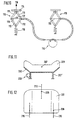
- the adjusting elements 116 according to FIG. 10 are designed as scissor-type lifting rods. She consist of a lower and an upper pair of scissors 111 and 112, respectively Cable 113 are moved. If cable 113 is shortened on the left Actuator 116 according to arrow 117, the scissors 111 and 112 in the direction transferred to their collapsed position, causing the transfer plate 114 is shifted upwards (arrow 119). The cable pull 113 is adjusted via a reciprocating drive 110, which on the two actuators 116 each produces an opposite movement. Parallel to raising the right one Actuator 116, the left actuator 116 by the weight of seated person and / or a spring 118 opposite in a lowered position transferred.
- FIGS. 11 and 12 show a seat cushion 201 with a single one on one side Stelliement 206 attacks.
- Actuator 206 from an eccentric drive in the left rear area of the Seat cushion 201.
- the seat cushion 201 has a rigid support structure 202 which extends over Springs 207 'with their rear attachment points 208 on two rear seat rail sections 210 and via a front connection point 211 at a middle one front seat rail section 212 is mounted.
- This "Three-point support" results from the illustrated one-sided adjustment movement Tilting of the seat cushion 201 by the eccentric drive 206 the tilt axis 207.
- FIG. 13 and 14 illustrate an inventive method for starting a geometric middle position in liquid-operated control elements, such as the actuators 86a and 86b of FIG. 7.
- Fig. 13 is the solid path s of the first actuating element with a solid line 86a plotted over time t. This is in phase opposition with the dashed Line indicated travel s of the second actuator 86b.
- Tilting movement of the seat cushion creates a movement of the lumbar sections the spine of a seated person.
- the individual phases of Tilting movement of the seat cushion about the tilt axis 7 is illustrated symbolically in FIG. 13.
- the actuating element 86a is first filled with liquid (filling time t F ) such that a central position M (half the maximum actuating travel) is established.
- the control element 86a is completely filled with the liquid (state V).
- the degree of filling is then reduced to such an extent that the middle position M is again set in order to subsequently return to the initial state L in the last section of the cycle.
- the filling and holding times t F and t H are the same in the selected example during the individual phases of the cycle and are constant over the cycle duration. For example, t F and t H are 10 seconds, so that the total cycle time is 80 seconds.
- Fig. 14 is the number N of the pump, for example a rotary vane pump 80, occurring impulses plotted over time t.
- pump 80 pumps the liquid from actuator 86a into the actuator 86b (solid line in the left part of the diagram), while in the in the second half of the cycle, the pumping direction is reversed (dashed line in the right part of the diagram).
- the factors F12 and F21 are made by the manufacturer does not determine and change over the life of the seating system noteworthy.
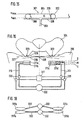
- FIG. 15 shows an actuating element 301 with flexible walls 302 (FIG. 15) and an air supply 303.
- the upper and lower walls 304 and 305 of the actuating element lie directly on top of one another.
- the pressurized state solid lines
- the two walls 304 and 305 are spaced apart from one another and form a bubble-shaped body.
- two webs 306 are provided, which are welded to the walls 304 and 305 of the control element 301.
- the webs 306 consist of a flexible but non-stretchable plastic material and form a path limitation in the direction of the travel s.
- a constant internal pressure p i is provided via the air supply 303, the force effect of which outweighs a maximum external weight load.
- the webs 306 limit the travel s to the value s max even at a lower load G.
- the depressurized state of the control element 301 represents the output path s min , the amount of which is determined by the wall thicknesses of the walls 304 and 305.
- the 16 are in a seat cushion 310 of a motor vehicle seat per seat half in each case two control elements 311a, b and 311c, d arranged one above the other.
- the individual adjusting elements 311a to 311d are comparable to the adjusting element 301 built up and via air supply 313 and valves 320 with a Pressure source 322 connected.
- the valves 320 are operated via a control device 321 controlled.
- the adjusting elements 311a to 311d are in the seat cushion 310, respectively beneath the seat bumps 323 of the pelvis 324, one seated on the seat cushion 310 Person arranged.
- the actuating elements 311a to 311d are either depressurized or acted upon by the operating pressure p i via the valves 320. Accordingly, the actuating elements 311a to 311d take up two exactly defined actuating heights s min or s max (analogously to FIG. 15).
- actuating heights s min or s max analogously to FIG. 15.
- the two dash-dotted lines 326 illustrate the two opposite maximum tilting positions of the pelvis 324, while the dashed line 327 represents the central position of the pelvis 324, in which only one actuating element 311a or 311b or 311c or 311d is pressurized on each side of the seat cushion.
- FIG. 18 shows an actuating device with two separate pressure sources 332, which supplies actuating elements 331a to 331d via air feeds 333.
- Each of the Pressure sources 332 each connect an adjusting element of one seat half to one Control element of the other half of the seat.
- the two pressure sources 332 work here in phase opposition, so that the adjusting elements 331a, b and 331c, d each have a seat half opposing pressure and a total tilting movement results as shown in Fig. 16.
Landscapes
- Engineering & Computer Science (AREA)
- Mechanical Engineering (AREA)
- Aviation & Aerospace Engineering (AREA)
- Transportation (AREA)
- Physics & Mathematics (AREA)
- Fluid Mechanics (AREA)
- General Engineering & Computer Science (AREA)
- Chemical & Material Sciences (AREA)
- Analytical Chemistry (AREA)
- Seats For Vehicles (AREA)
- Chair Legs, Seat Parts, And Backrests (AREA)
Applications Claiming Priority (5)
| Application Number | Priority Date | Filing Date | Title |
|---|---|---|---|
| DE19726410 | 1997-06-21 | ||
| DE19726410A DE19726410B4 (de) | 1997-06-21 | 1997-06-21 | Stelleinrichtung, insbesondere für einen Sitz |
| DE19726409A DE19726409A1 (de) | 1997-06-21 | 1997-06-21 | Sitz |
| DE19726409 | 1997-06-21 | ||
| PCT/EP1998/003810 WO1998058568A2 (de) | 1997-06-21 | 1998-06-22 | Sitz |
Publications (2)
| Publication Number | Publication Date |
|---|---|
| EP0991342A2 EP0991342A2 (de) | 2000-04-12 |
| EP0991342B1 true EP0991342B1 (de) | 2001-10-04 |
Family
ID=26037644
Family Applications (1)
| Application Number | Title | Priority Date | Filing Date |
|---|---|---|---|
| EP98938624A Expired - Lifetime EP0991342B1 (de) | 1997-06-21 | 1998-06-22 | Sitz |
Country Status (6)
| Country | Link |
|---|---|
| US (1) | US6398303B1 (enExample) |
| EP (1) | EP0991342B1 (enExample) |
| JP (1) | JP2002507900A (enExample) |
| DE (3) | DE19726410B4 (enExample) |
| ES (1) | ES2164450T3 (enExample) |
| WO (1) | WO1998058568A2 (enExample) |
Cited By (3)
| Publication number | Priority date | Publication date | Assignee | Title |
|---|---|---|---|---|
| DE102008032541A1 (de) | 2008-07-10 | 2010-01-14 | Bayerische Motoren Werke Aktiengesellschaft | Verfahren zur Ansteuerung eines Sitzes |
| DE102012209449A1 (de) | 2012-06-05 | 2013-12-05 | Conti Temic Microelectronic Gmbh | Verfahren und Vorrichtung zum Befüllen und Entleeren eines Sitzkissens |
| DE102015216945A1 (de) | 2015-09-04 | 2017-03-09 | Conti Temic Microelectronic Gmbh | Sitz für ein Verkehrsmittel, insbesondere für ein Kraftfahrzeug |
Families Citing this family (33)
| Publication number | Priority date | Publication date | Assignee | Title |
|---|---|---|---|---|
| DE19908655C1 (de) * | 1999-02-27 | 2000-08-31 | Faure Bertrand Sitztech Gmbh | Kraftfahrzeugsitz |
| DE10123947A1 (de) * | 2001-05-17 | 2002-12-05 | Zf Luftfahrttechnik Gmbh | Druckmittelbetätigbare Stelleranordnung |
| DE10238240A1 (de) * | 2002-08-21 | 2004-03-04 | Robert Bosch Gmbh | Verfahren zur Befüllung mindestens zweier Rezipienten sowie pneumatische Schaltung zur Durchführung des Verfahrens |
| WO2005005829A1 (de) * | 2003-07-10 | 2005-01-20 | Robert Bosch Gmbh | Kolbenmaschine |
| DE102004014881B4 (de) * | 2004-03-26 | 2008-02-28 | Recaro Gmbh & Co. Kg | Fahrzeugsitz mit Seitenwangen |
| GB2420494A (en) * | 2004-11-29 | 2006-05-31 | Ford Global Tech Llc | Motor vehicle seat including a cushion movable from a horizontal orientation to a transversely inclined orientation |
| NO327507B1 (no) * | 2006-03-15 | 2009-07-27 | Jurek Buchacz | Anordning for justering av sitteflaten pa en stol |
| DE102006018184A1 (de) * | 2006-04-19 | 2007-10-25 | Bayerische Motoren Werke Ag | Sitz |
| DE202007000441U1 (de) * | 2007-01-05 | 2008-05-15 | Brose Fahrzeugteile Gmbh & Co. Kommanditgesellschaft, Coburg | Kraftfahrzeugsitz mit Vibrator |
| US7806479B2 (en) * | 2007-02-14 | 2010-10-05 | Wisys Technology Foundation | Seat with adjustable dynamic joint |
| DE102007026368A1 (de) * | 2007-06-06 | 2008-12-11 | GM Global Technology Operations, Inc., Detroit | Kissen für ein Kraftfahrzeug, Kraftfahrzeugsitz mit einem solchen Kissen und Verfahren zur Herstellung eines solchen Kissens |
| DE102007053119A1 (de) | 2007-11-08 | 2009-05-14 | Bayerische Motoren Werke Aktiengesellschaft | Verfahren und Vorrichtung zum Einstellen eines Sitzes sowie Sitz |
| US7922247B2 (en) * | 2008-04-18 | 2011-04-12 | Spark Innovations, Inc. | Hydraulic adjustable seat |
| DE102008030102B4 (de) * | 2008-06-25 | 2010-02-11 | Faurecia Autositze Gmbh | Vorrichtung zur Verstellung von Komponenten oder Komponententeilen eines Fahrzeugsitzes |
| DE102010022020B4 (de) * | 2010-05-29 | 2014-03-06 | Audi Ag | Sitzvorrichtung und Einstellverfahren |
| DE102010056568A1 (de) | 2010-12-30 | 2012-07-05 | Aerovitt Systembau Gmbh | Mobile Sitzauflage |
| DE102011121120B3 (de) | 2011-12-14 | 2013-06-13 | Faurecia Autositze Gmbh | Kopfstütze für Kraftfahrzeugsitze |
| US10046677B2 (en) | 2013-04-23 | 2018-08-14 | Clearmotion Acquisition I Llc | Seat system for a vehicle |
| EP3086750B1 (en) | 2013-12-25 | 2020-12-23 | Mopair Technologies Ltd. | Apparatus for stimulating synchronized body motions of a user |
| US10328823B2 (en) | 2014-06-09 | 2019-06-25 | Lear Corporation | Adjustable seat assembly |
| US9987961B2 (en) | 2014-06-09 | 2018-06-05 | Lear Corporation | Adjustable seat assembly |
| US9718382B2 (en) | 2014-10-02 | 2017-08-01 | Bose Corporation | Seat suspension |
| DE102015204516A1 (de) * | 2015-03-12 | 2016-09-15 | Brose Fahrzeugteile Gmbh & Co. Kg, Coburg | Sitzstruktur für einen Fahrzeugsitz |
| US9884570B2 (en) | 2015-05-19 | 2018-02-06 | Lear Corporation | Adjustable seat assembly |
| US9845026B2 (en) | 2015-05-19 | 2017-12-19 | Lear Corporation | Adjustable seat assembly |
| US9661928B2 (en) | 2015-09-29 | 2017-05-30 | Lear Corporation | Air bladder assembly for seat bottoms of seat assemblies |
| US9758079B2 (en) | 2015-10-08 | 2017-09-12 | Lear Corporation | Adjustable seat assembly |
| US9827888B2 (en) | 2016-01-04 | 2017-11-28 | Lear Corporation | Seat assemblies with adjustable side bolster actuators |
| US10384565B2 (en) | 2016-07-29 | 2019-08-20 | Lear Corporation | Adjustable seat assembly |
| US10640010B2 (en) | 2016-12-29 | 2020-05-05 | Lear Corporation | Adjustable seat assembly |
| DE102017214313B4 (de) * | 2017-08-17 | 2021-05-27 | Conti Temic Microelectronic Gmbh | Stellvorrichtung für einen Fahrzeugsitz, Fahrzeugsitz und Verfahren zum Verändern einer Sitzanlagefläche |
| DE102017223557A1 (de) | 2017-12-21 | 2019-06-27 | Bayerische Motoren Werke Aktiengesellschaft | Sitz, insbesondere Fahrzeugsitz, und Fahrzeug mit einem Sitz |
| JP7527857B2 (ja) * | 2020-06-19 | 2024-08-05 | コクヨ株式会社 | 座、椅子および荷重支持体 |
Family Cites Families (27)
| Publication number | Priority date | Publication date | Assignee | Title |
|---|---|---|---|---|
| GB508095A (en) * | 1936-10-17 | 1939-06-23 | John Cockbill Junior | Improvements in adjustable seats for automobiles and the like |
| DE1247138B (de) * | 1963-03-12 | 1967-08-10 | Ingbuero Gebrueder Holtschmidt | Hydraulischer Antrieb mit einstellbarem Hub |
| DE1555946B2 (de) * | 1966-09-07 | 1978-04-13 | Kloeckner-Humboldt-Deutz Ag, 5000 Koeln | Arbeitsfahrzeug, insbesondere Schlepper |
| US3477071A (en) * | 1968-10-14 | 1969-11-11 | John H Emerson | Device for automatically shifting the body of a patient |
| DE1950866A1 (de) * | 1969-10-09 | 1971-04-29 | Eickhoff Geb | Vorrichtung zur Hubverstellung von vorzugsweise pneumatischen Zylindern,insbesondere fuer Verpackungsmaschinen od.dgl. |
| US3984146A (en) * | 1970-03-31 | 1976-10-05 | Siemens Aktiengesellschaft | Apparatus for actuating operational chairs |
| GB1374997A (en) * | 1971-10-11 | 1974-11-20 | Int Research & Dev Co Ltd | Hydraulically-operated manipulators or actuators |
| FR2293332A1 (fr) * | 1974-12-04 | 1976-07-02 | Renault Daniel | Stabilisateur de siege en position horizontale, pour tracteurs agricoles et vehicules similaires |
| DE2901208C2 (de) * | 1979-01-13 | 1984-08-09 | Keiper Automobiltechnik Gmbh & Co Kg, 5630 Remscheid | Verstellbarer Sitz, insbesondere Fahrzeugsitz |
| FR2472491A1 (fr) * | 1979-12-26 | 1981-07-03 | Levy Pierre | Siege a inclinaison reglable, notamment pour tracteur |
| DE3027560A1 (de) * | 1980-07-21 | 1982-02-18 | P.A. Rentrop Hubbert & Wagner, Fahrzeugausstattungen GmbH &Co KG, 3060 Stadthagen | Sitz, insbes. kraftfahrzeugsitz |
| DE8319792U1 (de) * | 1983-07-08 | 1983-10-20 | Ciecierski, Wolf, 8403 Bad Abbach | Buerostuhl |
| GB8529809D0 (en) * | 1985-12-04 | 1986-01-15 | Dermalex Co Ltd | Air supply & control apparatus |
| US4826247A (en) * | 1986-09-26 | 1989-05-02 | The Boeing Company | System for assisting a fighter pilot in checking the six-o'clock position |
| US5052067A (en) * | 1989-03-09 | 1991-10-01 | Ssi Medical Services, Inc. | Bimodal system for pressurizing a low air loss patient support |
| JP2670630B2 (ja) * | 1989-09-27 | 1997-10-29 | 株式会社豊田中央研究所 | 着座疲労防止装置 |
| JPH03220031A (ja) | 1990-01-26 | 1991-09-27 | Daihatsu Motor Co Ltd | 乗物のシート姿勢調整装置 |
| JPH03253435A (ja) | 1990-03-03 | 1991-11-12 | Daihatsu Motor Co Ltd | 自動車のシート傾動装置 |
| JPH04197315A (ja) * | 1990-11-29 | 1992-07-16 | Nissan Motor Co Ltd | シート |
| US5184365A (en) * | 1990-12-07 | 1993-02-09 | Trustees Of Boston University | Method and apparatus of a positioning system for airway management |
| DE4137063A1 (de) * | 1991-11-11 | 1993-05-13 | Weiss Maschf Johann | Parallelstangendoppelzylinder |
| FR2697419B1 (fr) * | 1992-11-04 | 1994-12-09 | Tritube | Siège inclinable. |
| EP0600135B1 (en) * | 1992-12-04 | 1997-03-12 | Fukuoka Kagaku Ltd. | Vibratile seat |
| JP3253435B2 (ja) | 1993-12-16 | 2002-02-04 | 松下電器産業株式会社 | 数値制御装置 |
| US5571005A (en) * | 1995-06-07 | 1996-11-05 | Delaware Capital Formation, Inc. | Hinged vane rotary pump |
| DE29522051U1 (de) * | 1995-12-21 | 1999-07-01 | Fitz, Wolfgang, Dr., South Natick, Mass. | Sitzelement |
| JP3220031B2 (ja) | 1996-11-26 | 2001-10-22 | エヌイーシーマイクロシステム株式会社 | 文字表示装置の表示制御回路およびその制御方法 |
-
1997
- 1997-06-21 DE DE19726410A patent/DE19726410B4/de not_active Expired - Fee Related
- 1997-06-21 DE DE19726409A patent/DE19726409A1/de not_active Withdrawn
-
1998
- 1998-06-22 JP JP50379599A patent/JP2002507900A/ja active Pending
- 1998-06-22 WO PCT/EP1998/003810 patent/WO1998058568A2/de not_active Ceased
- 1998-06-22 EP EP98938624A patent/EP0991342B1/de not_active Expired - Lifetime
- 1998-06-22 ES ES98938624T patent/ES2164450T3/es not_active Expired - Lifetime
- 1998-06-22 US US09/446,262 patent/US6398303B1/en not_active Expired - Lifetime
- 1998-06-22 DE DE59801650T patent/DE59801650D1/de not_active Expired - Lifetime
Cited By (7)
| Publication number | Priority date | Publication date | Assignee | Title |
|---|---|---|---|---|
| DE102008032541A1 (de) | 2008-07-10 | 2010-01-14 | Bayerische Motoren Werke Aktiengesellschaft | Verfahren zur Ansteuerung eines Sitzes |
| US9238426B2 (en) | 2008-07-10 | 2016-01-19 | Bayerische Motoren Werke Aktiengesellschaft | Method for actuating a seat |
| DE102008032541B4 (de) | 2008-07-10 | 2021-09-02 | Bayerische Motoren Werke Aktiengesellschaft | Verfahren zur Ansteuerung eines Sitzes |
| DE102012209449A1 (de) | 2012-06-05 | 2013-12-05 | Conti Temic Microelectronic Gmbh | Verfahren und Vorrichtung zum Befüllen und Entleeren eines Sitzkissens |
| WO2013182600A1 (de) | 2012-06-05 | 2013-12-12 | Conti Temic Microelectronic Gmbh | Verfahren und vorrichtung zum befüllen und entleeren eines sitzkissens |
| DE102015216945A1 (de) | 2015-09-04 | 2017-03-09 | Conti Temic Microelectronic Gmbh | Sitz für ein Verkehrsmittel, insbesondere für ein Kraftfahrzeug |
| DE102015216945B4 (de) | 2015-09-04 | 2023-06-07 | Conti Temic Microelectronic Gmbh | Verfahren zur Bewegung von Körperteilen einer in einem Sitz fürein Verkehrsmittel sitzenden Person, Sitz zum Durchführen einesderartigen Verfahrens, sowie Verkehrsmittel, insbesondere Kraftfahrzeug, mit einem derartigen Sitz |
Also Published As
| Publication number | Publication date |
|---|---|
| DE19726409A1 (de) | 1998-12-24 |
| US6398303B1 (en) | 2002-06-04 |
| DE19726410A1 (de) | 1998-12-24 |
| JP2002507900A (ja) | 2002-03-12 |
| WO1998058568A3 (de) | 1999-04-22 |
| DE59801650D1 (de) | 2001-11-08 |
| ES2164450T3 (es) | 2002-02-16 |
| WO1998058568A2 (de) | 1998-12-30 |
| DE19726410B4 (de) | 2008-04-30 |
| EP0991342A2 (de) | 2000-04-12 |
Similar Documents
| Publication | Publication Date | Title |
|---|---|---|
| EP0991342B1 (de) | Sitz | |
| EP3972873B1 (de) | Luftkissenanordnung für einen sitz, wie etwa einen fahrzeugsitz | |
| EP2414191B1 (de) | Sitz mit einer auflage und verfahren zur anpassung der kontur des sitzes | |
| DE102008032541B4 (de) | Verfahren zur Ansteuerung eines Sitzes | |
| DE60100412T2 (de) | Sitzfläche mit massierender Wirkung, insbesondere für Kraftfahrzeuge. | |
| AT502780B1 (de) | System zur automatischen verstellung der sitz-kontur sowie sitz, insbesondere fahrzeugsitz für automobile, flugzeuge oder dergleichen | |
| EP1904337A2 (de) | Pneumatisch verstellbare seitenwangen für fahrzeugsitze | |
| EP1077154A2 (de) | Fahrzeugsitz | |
| EP3142892B1 (de) | Fahrzeugsitz mit einstellbarer sitzfläche und verfahren zum verstellen einer einstellbaren sitzfläche | |
| EP2149475A1 (de) | Sitz mit Formeinrichtung zur Verstellung der Sitzkontur | |
| DE102007051759A1 (de) | Sitz | |
| DE102018127495A1 (de) | Kraftfahrzeugsitz | |
| DE102005016184A1 (de) | Kraftfahrzeugsitz, sowie Vorrichtung und Verfahren zum Befüllen und/oder Entlüften von aufblasbaren Kissen | |
| EP1532016B1 (de) | VERFAHREN ZUR BEFüLLUNG MINDESTENS ZWEIER REZIPIENTEN SOWIE PNEUMATISCHE SCHALTUNG ZUR DURCHFüHRUNG DES VERFAHRENS | |
| DE102006012784B4 (de) | Fahrzeugsitz mit veränderbarer Geometrie | |
| DE102005050975B4 (de) | Sitz, insbesondere für Kraftfahrzeuge, sowie ein Verfahren zum Ändern der Kontur eines Sitzes | |
| DE102021122458A1 (de) | Verfahren zum Betreiben der Massagefunktion eines Kraftfahrzeugsitzes in einem Kraftfahrzeugsitzsystem | |
| EP1689267B1 (de) | Sitzlehnenregulierung | |
| DE102023103100B4 (de) | Luftkissenvorrichtung und Sitz mit einer solchen Luftkissenvorrichtung | |
| DE102004060816A1 (de) | Fahrzeugsitz | |
| DE102006016899B4 (de) | Sitz | |
| DE29623496U1 (de) | Aufblasbares Kissen für Fahrzeugsitze | |
| DE102023004472A1 (de) | Luftkissenvorrichtung und Sitz mit einer solchen Luftkissenvorrichtung | |
| DE202023100608U1 (de) | Luftkissenvorrichtung und Sitz mit einer solchen Luftkissenvorrichtung | |
| WO2024165295A1 (de) | Luftkissenvorrichtung und sitz mit einer solchen luftkissenvorrichtung sowie massageverfahren zur beaufschlagung einer luftkissenvorrichtung mit einer pulsation |
Legal Events
| Date | Code | Title | Description |
|---|---|---|---|
| PUAI | Public reference made under article 153(3) epc to a published international application that has entered the european phase |
Free format text: ORIGINAL CODE: 0009012 |
|
| 17P | Request for examination filed |
Effective date: 19991118 |
|
| AK | Designated contracting states |
Kind code of ref document: A2 Designated state(s): DE ES FR GB IT |
|
| GRAG | Despatch of communication of intention to grant |
Free format text: ORIGINAL CODE: EPIDOS AGRA |
|
| GRAG | Despatch of communication of intention to grant |
Free format text: ORIGINAL CODE: EPIDOS AGRA |
|
| GRAH | Despatch of communication of intention to grant a patent |
Free format text: ORIGINAL CODE: EPIDOS IGRA |
|
| 17Q | First examination report despatched |
Effective date: 20010309 |
|
| GRAH | Despatch of communication of intention to grant a patent |
Free format text: ORIGINAL CODE: EPIDOS IGRA |
|
| GRAA | (expected) grant |
Free format text: ORIGINAL CODE: 0009210 |
|
| AK | Designated contracting states |
Kind code of ref document: B1 Designated state(s): DE ES FR GB IT |
|
| GBT | Gb: translation of ep patent filed (gb section 77(6)(a)/1977) |
Effective date: 20011004 |
|
| REF | Corresponds to: |
Ref document number: 59801650 Country of ref document: DE Date of ref document: 20011108 |
|
| ET | Fr: translation filed | ||
| REG | Reference to a national code |
Ref country code: GB Ref legal event code: IF02 |
|
| REG | Reference to a national code |
Ref country code: ES Ref legal event code: FG2A Ref document number: 2164450 Country of ref document: ES Kind code of ref document: T3 |
|
| PLBE | No opposition filed within time limit |
Free format text: ORIGINAL CODE: 0009261 |
|
| STAA | Information on the status of an ep patent application or granted ep patent |
Free format text: STATUS: NO OPPOSITION FILED WITHIN TIME LIMIT |
|
| 26N | No opposition filed | ||
| PGFP | Annual fee paid to national office [announced via postgrant information from national office to epo] |
Ref country code: IT Payment date: 20120626 Year of fee payment: 15 |
|
| PG25 | Lapsed in a contracting state [announced via postgrant information from national office to epo] |
Ref country code: IT Free format text: LAPSE BECAUSE OF NON-PAYMENT OF DUE FEES Effective date: 20130622 |
|
| REG | Reference to a national code |
Ref country code: FR Ref legal event code: PLFP Year of fee payment: 19 |
|
| REG | Reference to a national code |
Ref country code: FR Ref legal event code: PLFP Year of fee payment: 20 |
|
| PGFP | Annual fee paid to national office [announced via postgrant information from national office to epo] |
Ref country code: FR Payment date: 20170621 Year of fee payment: 20 Ref country code: DE Payment date: 20170624 Year of fee payment: 20 Ref country code: GB Payment date: 20170626 Year of fee payment: 20 |
|
| PGFP | Annual fee paid to national office [announced via postgrant information from national office to epo] |
Ref country code: ES Payment date: 20170703 Year of fee payment: 20 |
|
| REG | Reference to a national code |
Ref country code: DE Ref legal event code: R071 Ref document number: 59801650 Country of ref document: DE |
|
| REG | Reference to a national code |
Ref country code: GB Ref legal event code: PE20 Expiry date: 20180621 |
|
| PG25 | Lapsed in a contracting state [announced via postgrant information from national office to epo] |
Ref country code: GB Free format text: LAPSE BECAUSE OF EXPIRATION OF PROTECTION Effective date: 20180621 |
|
| REG | Reference to a national code |
Ref country code: ES Ref legal event code: FD2A Effective date: 20201204 |
|
| PG25 | Lapsed in a contracting state [announced via postgrant information from national office to epo] |
Ref country code: ES Free format text: LAPSE BECAUSE OF EXPIRATION OF PROTECTION Effective date: 20180623 |