EP0991342B1 - Seat - Google Patents
Seat Download PDFInfo
- Publication number
- EP0991342B1 EP0991342B1 EP98938624A EP98938624A EP0991342B1 EP 0991342 B1 EP0991342 B1 EP 0991342B1 EP 98938624 A EP98938624 A EP 98938624A EP 98938624 A EP98938624 A EP 98938624A EP 0991342 B1 EP0991342 B1 EP 0991342B1
- Authority
- EP
- European Patent Office
- Prior art keywords
- seat
- adjusting
- cushion
- adjusting elements
- elements
- Prior art date
- Legal status (The legal status is an assumption and is not a legal conclusion. Google has not performed a legal analysis and makes no representation as to the accuracy of the status listed.)
- Expired - Lifetime
Links
Images


Classifications
-
- B—PERFORMING OPERATIONS; TRANSPORTING
- B60—VEHICLES IN GENERAL
- B60N—SEATS SPECIALLY ADAPTED FOR VEHICLES; VEHICLE PASSENGER ACCOMMODATION NOT OTHERWISE PROVIDED FOR
- B60N2/00—Seats specially adapted for vehicles; Arrangement or mounting of seats in vehicles
- B60N2/02—Seats specially adapted for vehicles; Arrangement or mounting of seats in vehicles the seat or part thereof being movable, e.g. adjustable
- B60N2/04—Seats specially adapted for vehicles; Arrangement or mounting of seats in vehicles the seat or part thereof being movable, e.g. adjustable the whole seat being movable
- B60N2/16—Seats specially adapted for vehicles; Arrangement or mounting of seats in vehicles the seat or part thereof being movable, e.g. adjustable the whole seat being movable height-adjustable
- B60N2/18—Seats specially adapted for vehicles; Arrangement or mounting of seats in vehicles the seat or part thereof being movable, e.g. adjustable the whole seat being movable height-adjustable the front or the rear portion of the seat being adjustable, e.g. independently of each other
- B60N2/1807—Seats specially adapted for vehicles; Arrangement or mounting of seats in vehicles the seat or part thereof being movable, e.g. adjustable the whole seat being movable height-adjustable the front or the rear portion of the seat being adjustable, e.g. independently of each other characterised by the cinematic
- B60N2/181—Rods
-
- A—HUMAN NECESSITIES
- A47—FURNITURE; DOMESTIC ARTICLES OR APPLIANCES; COFFEE MILLS; SPICE MILLS; SUCTION CLEANERS IN GENERAL
- A47C—CHAIRS; SOFAS; BEDS
- A47C7/00—Parts, details, or accessories of chairs or stools
- A47C7/02—Seat parts
- A47C7/14—Seat parts of adjustable shape; elastically mounted ; adaptable to a user contour or ergonomic seating positions
-
- A—HUMAN NECESSITIES
- A47—FURNITURE; DOMESTIC ARTICLES OR APPLIANCES; COFFEE MILLS; SPICE MILLS; SUCTION CLEANERS IN GENERAL
- A47C—CHAIRS; SOFAS; BEDS
- A47C9/00—Stools for specified purposes
- A47C9/002—Stools for specified purposes with exercising means or having special therapeutic or ergonomic effects
-
- B—PERFORMING OPERATIONS; TRANSPORTING
- B60—VEHICLES IN GENERAL
- B60N—SEATS SPECIALLY ADAPTED FOR VEHICLES; VEHICLE PASSENGER ACCOMMODATION NOT OTHERWISE PROVIDED FOR
- B60N2/00—Seats specially adapted for vehicles; Arrangement or mounting of seats in vehicles
- B60N2/02—Seats specially adapted for vehicles; Arrangement or mounting of seats in vehicles the seat or part thereof being movable, e.g. adjustable
- B60N2/04—Seats specially adapted for vehicles; Arrangement or mounting of seats in vehicles the seat or part thereof being movable, e.g. adjustable the whole seat being movable
- B60N2/10—Seats specially adapted for vehicles; Arrangement or mounting of seats in vehicles the seat or part thereof being movable, e.g. adjustable the whole seat being movable tiltable
-
- B—PERFORMING OPERATIONS; TRANSPORTING
- B60—VEHICLES IN GENERAL
- B60N—SEATS SPECIALLY ADAPTED FOR VEHICLES; VEHICLE PASSENGER ACCOMMODATION NOT OTHERWISE PROVIDED FOR
- B60N2/00—Seats specially adapted for vehicles; Arrangement or mounting of seats in vehicles
- B60N2/02—Seats specially adapted for vehicles; Arrangement or mounting of seats in vehicles the seat or part thereof being movable, e.g. adjustable
- B60N2/04—Seats specially adapted for vehicles; Arrangement or mounting of seats in vehicles the seat or part thereof being movable, e.g. adjustable the whole seat being movable
- B60N2/16—Seats specially adapted for vehicles; Arrangement or mounting of seats in vehicles the seat or part thereof being movable, e.g. adjustable the whole seat being movable height-adjustable
- B60N2/18—Seats specially adapted for vehicles; Arrangement or mounting of seats in vehicles the seat or part thereof being movable, e.g. adjustable the whole seat being movable height-adjustable the front or the rear portion of the seat being adjustable, e.g. independently of each other
- B60N2/185—Seats specially adapted for vehicles; Arrangement or mounting of seats in vehicles the seat or part thereof being movable, e.g. adjustable the whole seat being movable height-adjustable the front or the rear portion of the seat being adjustable, e.g. independently of each other characterised by the drive mechanism
- B60N2/1853—Linear actuator, e.g. screw mechanism
-
- B—PERFORMING OPERATIONS; TRANSPORTING
- B60—VEHICLES IN GENERAL
- B60N—SEATS SPECIALLY ADAPTED FOR VEHICLES; VEHICLE PASSENGER ACCOMMODATION NOT OTHERWISE PROVIDED FOR
- B60N2/00—Seats specially adapted for vehicles; Arrangement or mounting of seats in vehicles
- B60N2/02—Seats specially adapted for vehicles; Arrangement or mounting of seats in vehicles the seat or part thereof being movable, e.g. adjustable
- B60N2/04—Seats specially adapted for vehicles; Arrangement or mounting of seats in vehicles the seat or part thereof being movable, e.g. adjustable the whole seat being movable
- B60N2/16—Seats specially adapted for vehicles; Arrangement or mounting of seats in vehicles the seat or part thereof being movable, e.g. adjustable the whole seat being movable height-adjustable
- B60N2/18—Seats specially adapted for vehicles; Arrangement or mounting of seats in vehicles the seat or part thereof being movable, e.g. adjustable the whole seat being movable height-adjustable the front or the rear portion of the seat being adjustable, e.g. independently of each other
- B60N2/185—Seats specially adapted for vehicles; Arrangement or mounting of seats in vehicles the seat or part thereof being movable, e.g. adjustable the whole seat being movable height-adjustable the front or the rear portion of the seat being adjustable, e.g. independently of each other characterised by the drive mechanism
- B60N2/1878—Hydraulic or pneumatic actuation
-
- B—PERFORMING OPERATIONS; TRANSPORTING
- B60—VEHICLES IN GENERAL
- B60R—VEHICLES, VEHICLE FITTINGS, OR VEHICLE PARTS, NOT OTHERWISE PROVIDED FOR
- B60R16/00—Electric or fluid circuits specially adapted for vehicles and not otherwise provided for; Arrangement of elements of electric or fluid circuits specially adapted for vehicles and not otherwise provided for
- B60R16/08—Electric or fluid circuits specially adapted for vehicles and not otherwise provided for; Arrangement of elements of electric or fluid circuits specially adapted for vehicles and not otherwise provided for fluid
-
- F—MECHANICAL ENGINEERING; LIGHTING; HEATING; WEAPONS; BLASTING
- F15—FLUID-PRESSURE ACTUATORS; HYDRAULICS OR PNEUMATICS IN GENERAL
- F15B—SYSTEMS ACTING BY MEANS OF FLUIDS IN GENERAL; FLUID-PRESSURE ACTUATORS, e.g. SERVOMOTORS; DETAILS OF FLUID-PRESSURE SYSTEMS, NOT OTHERWISE PROVIDED FOR
- F15B11/00—Servomotor systems without provision for follow-up action; Circuits therefor
- F15B11/16—Servomotor systems without provision for follow-up action; Circuits therefor with two or more servomotors
- F15B11/20—Servomotor systems without provision for follow-up action; Circuits therefor with two or more servomotors controlling several interacting or sequentially-operating members
-
- F—MECHANICAL ENGINEERING; LIGHTING; HEATING; WEAPONS; BLASTING
- F15—FLUID-PRESSURE ACTUATORS; HYDRAULICS OR PNEUMATICS IN GENERAL
- F15B—SYSTEMS ACTING BY MEANS OF FLUIDS IN GENERAL; FLUID-PRESSURE ACTUATORS, e.g. SERVOMOTORS; DETAILS OF FLUID-PRESSURE SYSTEMS, NOT OTHERWISE PROVIDED FOR
- F15B15/00—Fluid-actuated devices for displacing a member from one position to another; Gearing associated therewith
- F15B15/08—Characterised by the construction of the motor unit
- F15B15/10—Characterised by the construction of the motor unit the motor being of diaphragm type
- F15B15/103—Characterised by the construction of the motor unit the motor being of diaphragm type using inflatable bodies that contract when fluid pressure is applied, e.g. pneumatic artificial muscles or McKibben-type actuators
Definitions
- the invention relates to a seat according to the preamble of claims 1 and 20 and a method for controlling a seat according to the preamble of claims 21 and 22.
- All types of seating elements with a Referred to as a seat cushion and possibly a backrest for example office chairs, Bicycle saddles, seats in motor vehicles, etc.
- the object of the invention is to show ways to the described tilting movement to produce seats, in particular vehicle seats.
- the seat cushion there is at least one pair of adjusting elements in the area of the seat cushion intended.
- These two control elements are located opposite each other Arrange areas of the seat cushion and control it so that it is a perform the opposite stroke movement between a lower and an upper position.
- the opposite upward and downward movement becomes a tilting movement reached about a longitudinal or transverse axis of the seat. It is about make sure that the tilt axis is as close as possible to the buttocks of the on the Seat cushion seated person lies. Due to the control elements only a pure tilting movement be generated; an up and down movement of the seated person, which would have a lasting impact on well-being is imperative to avoid.
- Claims 2 to 4 show different possibilities for the arrangement of the adjusting elements.
- the entire seat is tilted, which can be implemented especially with seat constructions with a rigid seat shell.
- the adjusting elements are arranged between the support structure and the cushion part.
- the support structure can in turn be spring-loaded. If the adjusting elements are arranged directly in the upholstery part (claim 4), only minor changes to the supporting structure of the seat are required. Due to the small distance between the adjusting elements and the seat bumps of the seated person, the tilting movement is transmitted directly.
- the control elements can also be arranged in a direct line below the ischial humps.
- Adjusting elements according to claim 5 are particularly simple in construction and adaptation to the respective application. They are also inexpensive to manufacture.
- elements with flexible walls come as control elements in question, e.g. B. bubbles or bellows made of a rubber-elastic material. Due to the relatively large weight forces exerted by the seated person it is advisable to reinforce the bladders, bellows, etc. with a fabric insert.
- Bellows are particularly suitable because they have flat, have rigid limits for connection to the seat structure. Same effect Short-stroke cylinders with rigid can also be used for the above-mentioned control elements Chamber wall can be used.
- Such cylinders are characterized by a accordingly large diameter with a small adjustment path and stress thus an installation space that essentially takes up the space required for bellows-type control elements corresponds.
- the actuating elements according to claim 5 can be operated with air or with a liquid.
- Air-filled adjusting elements are particularly suitable for an arrangement in the upholstered part of the seat cushion, since they adapt to the shape of the seat bumps and do not give the impression of a hard insert. Because of the pressure and temperature dependence of the air volume in the control elements, however, suitable measures for regulating the adjustment path of the control elements are required, for example by means of distance measurement on the control elements.
- the control elements are operated with a liquid medium, a defined and reproducible control path can be realized due to the incompressibility of the liquid, so that the control or regulation of the control path can be carried out via a simple measurement of the volume flow to and from the control element. Due to the intransigence of liquid-filled actuating elements, however, an arrangement directly in the upholstery near the seat bumps of a seated person is only possible with restrictions.
- the medium for the control elements in separate working chambers provided. With the transfer of the medium from the first working chamber the medium from the other is simultaneously in the associated control element Pulled actuator in the second working chamber, so that the invention Push-pull sets automatically.
- the emptying of the control element which is in its elevated position is determined by the weight of the seated Person supports.
- the working chambers as well as the drive for the volume shift can advantageously outside the immediate seating area be arranged so that only one within the seat or the seat cushion little space is required.
- the tilting movement for example, by a double-acting pneumatic or hydraulic cylinders can be realized.
- a liquid working medium can be defined and measured by measuring the piston stroke reproducible working stroke of the control elements can be achieved.
- Working chambers formed can also be bellows-shaped working chambers (Claim 8) may be provided.
- a piston pump can also be used instead of a rotary vane pump be, which are also measurable when using a liquid medium Volume flow promotes.
- the application is due to the pulsations that occur of piston pumps limited to smaller individual volumes. Where applicable Use multi-piston pumps.
- Elements with flexible walls are preferred as adjusting elements, e.g. B. bubbles or bellows made of a rubber-elastic material. Because of the relative large acting weight forces by the seated person it is recommended reinforce the bladders, bellows, etc. with a fabric insert. Using bubble-like control elements result in a very small space requirement, since the overall height the control elements in the initial state only by the sum of their Wall thickness is determined.
- Rolled bellows are also particularly suitable because they have flat, rigid boundaries on the top and bottom for connection to the Have seat structure. Can have the same effect on the control elements mentioned short-stroke cylinders with rigid chamber walls can also be used.
- Such Cylinders are characterized by a correspondingly large diameter with a small one Adjustment path and thus take up an installation space that is essentially corresponds to the space required for bellows-type control elements.
- Adjustment heights With two control elements arranged one above the other, there are three defined ones Adjustment heights:
- the depressurized state of both control elements marks the lower position, whose overall height, for example, in the case of bubble-like control elements, is achieved solely by Sum of the wall thicknesses of the two bubbles is determined.
- a middle position results from pressurization of one of the two control elements while the second control element remains depressurized.
- the top position can go through Pressurization of both control elements can be started in a defined manner. Become the two control elements are designed in the same way, a middle position can be reached be exactly in the geometric center between the lower and upper position lies.
- Adjustment elements in the two seat cushion areas will tilt the Achieves pelvis about the longitudinal or transverse axis of the seat, as described in claim 22.
- the claimed control includes the same also embodiments with more than two arranged one above the other Control elements.
- Pneumatic control elements are generally of a simpler structure and easier to control than liquid-filled actuators. Because of the compressibility of the gaseous medium and its strong temperature dependence however, the (maximum) travel is not reproducible. Therefore, according to claim 12 proposed by an additional device on the actuator Limit the adjustment path automatically. Thus, regardless of the load of the pneumatic control element, each with a defined maximum travel range complied with, provided that the actuating element is subjected to an internal pressure which is larger than it is due to the effective inner surface of the actuator and would be necessary for a seated person. This ensures that without additional measures, such as a distance measurement, a constant adjustment path is maintained.
- path limits are provided in the interior of the actuating element. These path limitations preferably consist of a flexible, not stretchy material. You can use control elements with walls made of one Plastic material welded directly to the actuator during manufacture become. This results in a particularly simple structure and an inexpensive one Manufacturing.
- the wall sections - viewed in the adjustment direction - can be opposite with control elements made of a plastic material in sections with each other are welded so that there is also a through these welds Path limitation results (comparable to the stitching, for example with air mattresses).
- Path limitation results (comparable to the stitching, for example with air mattresses).
- the partially or circumferentially annular wrapping of the actuating element for example, with tapes made of flexible and non-stretch material he follows.
- the path limitation on the outer circumference of the actuating element is preferred additionally fixed to reliably prevent the actuator from slipping when depressurized to prevent.
- the two seat halves provided a shut-off valve be reliable, through which an exchange of the medium between the control elements is prevented.
- the shut-off valve is activated by the user, if the device for generating a tilting movement is switched off and that Seat cushions should be fixed in an "oblique" position by using the adjusting elements in different height positions can be “locked”.
- the shut-off valve turns on slow overflow of the medium, e.g. B. due to leakage in a pump, prevented.
- Such an application is considered, for example, for seat users, who, for orthopedic reasons, need to tilt the seat cushion.
- Claims 15 to 19 show examples of further basic principles of action of control elements.
- the principles of action mentioned can be achieved by a motor Actuator, for example an electric motor or with one Pressure media are implemented. Electric motors in particular are characterized by small space requirement and their easy controllability.
- the motor Actuators can be combined with all known transmission elements, for example with rotary or linear gears, eccentrics, racks, etc. With pressure medium drive due to the better control options and the higher working pressures preferred hydraulic media.
- Spindle drives according to claim 16 are driven by a rotary motor and convert its rotational movement into a vertical movement. Is preferred to provide a common drive shaft for the adjusting elements arranged in pairs. This applies analogously to eccentric drives according to claim 17 and Lifting linkage according to claim 18.
- wedge-shaped elements in particular wedge-shaped disks, the can be rotated against each other, height changes in the area of the seat bumps the seated person can be reached.
- the wedge disks can be used Reduction of the friction on rolling elements against each other.
- the tilt of the seat cushion by a one-sided attack Control element realized.
- This tilt is particularly useful for such seats, the seat cushion of which has a rigid "seat pan", as a whole is tiltable about a predetermined central axis.
- Tilting over one sided Attacking actuator can also be found in seats with a spring core substructure apply, in which case a tilt axis automatically in the middle of the seat cushion.
- the actuator is preferably outside of the Support structure of the seat cushion arranged. Also an arrangement of the control element between the supporting structure and the upholstered part is possible.
- control elements come for example basically all the above-mentioned embodiments in question.
- Claim 21 describes a method with which, regardless of the seat position or the body weight of the seat user, a constant central position for a bubble-like adjusting element (according to claim 5) can be achieved.
- Certain types of pumps e.g. rotary vane pumps
- the fluid flow delivered is, however, dependent on various parameters, e.g. B. Drive direction of the pump, pumping or suction operation, level of pressure against which the pumping or suction is carried out, etc.
- N12 and N21 indicate how many pulses each for the complete pumping the liquid between the two control elements are required.
- the Dimensional figures N12 and N21 are calculated with previously empirically determined factors F12 and F21 multiplied.
- the factors F12 and F21 are executed for a particular one Consistent unit of seat and control elements. Since the factors F12 and F21 in usually differ only slightly from each other, can be for the two pump directions to simplify work with a uniform factor F.
- the seat load is largely determined by the body weight of the seat user and the Contact area between the seat user and the seat cushion determined. Besides The seating position of the seat user also influences the values N12 and N21, depending on whether the right or left or the front or rear half of the seat is heavier become.
- the system thus arises according to the method according to the invention not only to different seat users, but also dynamically changing seating positions of the same seat user.
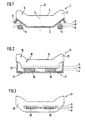
- Fig. 1 shows a seat cushion 1, which consists of a support structure 2 and a cushion part 3 composed.
- the middle part of the seat cushion 1 is designed as a seat surface 4, while the lateral areas 5 are designed in a wuist shape.
- At the bottom of the Support structure 2 attack on the right and left outside actuating elements 6, respectively take a middle layer M as well as an upper and a lower position O and U respectively can.
- a seat suspension is resilient within certain limits (Suspension 8), when the right and left move in opposite directions Adjusting elements 6 generates a tilting movement of the seat cushion about a tilting axis 7, which lies in the longitudinal center plane 9 of the seat cushion 1.
- Fig. 2 shows a seat cushion 11, in which the adjusting elements 16 between the Support structure 12 and the cushion part 13 are arranged. Above all, they are suitable for this flat actuators 16.
- the individual positions that the actuators 16 can take, are again designated M, O and U. Transition areas 18 between the beads rigidly connected to the support structure 12 15 and the seat surface 14 allow compensation by the adjusting elements 16 caused tilting movements.
- the support structure 12 can in turn be sprung be, as illustrated in FIG. 2 by means of the springs 17 shown in broken lines.
- FIG. 3 shows a further possibility of introducing adjusting elements 26 into a Seat cushion 21, which in turn consists of a support structure (not shown) and a cushion part 23 is composed.
- the adjusting elements 26 are preferably air-filled Bubbles or low-profile roll bellows executed. You can in the upholstered part inserted or glued or also foamed by the material of the cushion part 23 his.
- 4 to 7 show different ways of driving actuating elements via a liquid or gaseous medium.
- a double-acting cylinder 40 is shown, the connecting lines 41 controls 46a and 46b.
- the cylinder has a first and a second working chamber 42 and 43, which are separated by a piston 44 are separated.
- the piston can be moved via a piston rod 45, the volumes of the two working chambers 42 and 43 in opposite directions Wise enlarge or reduce.
- a second piston rod 47 provides the same volume in the two working chambers 42 and 43 safely.
- the actuator 46a is formed as a bubble-shaped structure with walls 48 that are flexible on all sides, while the actuator 46b of a bellows-like structure with an upper and a lower cover plate 49 or 50 and a rubber-elastic bellows 51 is formed.
- the working chambers 62 and 63 are in one housing 60 recorded and are formed by bladders or bellows that over Connecting lines 61 are connected to control elements, not shown.
- the housing 60 guides a slide 64, which is parallel to the lateral boundary walls 65 of the housing 60 can be moved (path s).
- the two working chambers 72 and 73 arranged in a housing 70 which is approximately V-shaped in cross section.
- a Swivel plate 74 is at the intersection of the two boundary walls 75 of the Housing 70 pivotally mounted (pivot axis 71), so that the plate 74 at a force introduction z. B. at the point of application 77 or torque initiation the pivot axis 71 can be adjusted (pivot angle ⁇ ).
- the adjusting elements according to FIGS. 4 to 6 are via separate fluid circuits adjusted in opposite directions.
- the adjustment can be made, for example, via a reciprocating linear drive, an eccentric drive, etc. take place.
- liquid media become almost constant travel ranges regardless of load reached on the control elements.
- a reservoir Working chambers 42, 43 or 62, 63 or 72, 73
- Control elements are filled or emptied.
- the adjusting elements 86a and 86b according to FIG. 7 are via a Rotary vane pump 80 directly connected to each other and become in opposite directions pressurized.
- the rotary vane pump 80 has a plurality of chambers 81, which promote a defined chamber volume.
- the individual chambers 81 are over radially movable slide 82 separated from each other and opposite the pump housing 83 sealed.
- the arrangement shown in FIG. 7 allows separate Chambers for providing the working medium are dispensed with, whereby a particularly compact design results.
- the rotary vane pump 80 can for example driven by an electric motor, the speed of which is about a Hall sensor is detected, so that when moving liquid media the travel the actuating elements 86a and 86b can be controlled or regulated in a simple manner can.
- shutt-off valve 89 is provided, with which an exchange of the medium between the two control elements 86a and 86b can be prevented to a static To achieve "misalignment" of the seat cushion of the vehicle seat.
- the misalignment is achieved, for example, in that the blocking in the de-energized state Valve 89 is energized briefly, so that the leakage gap of the rotary vane pump 80 under the weight and possibly a consciously influenced weight distribution a leakage current flows from the seat user and the desired one Skew.
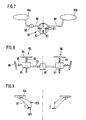
- FIG. 8 shows adjusting elements 96, each of which has a spindle nut 91 and a spindle 92 exhibit. Both actuating elements 96 are driven by a drive shaft 93 Electric motor 90 driven.
- the spindle nuts 91 set the rotational movement the shaft 93 in a vertical movement of the plate-shaped transmission elements 94 um.
- the spindle nuts 91 are via springs 95 in relation to the seat structure 98 supported.
- the pairings "spindle nut 91 - spindle 92" have one half of the seat cushion a right-hand or left-hand thread to turn the shaft 93 to achieve an opposite movement of the two transfer plates 94.
- Fig. 9 shows lever assemblies 101, with which a direct introduction of force on transmission plates 104 takes place.
- the transfer plates 104 are direct, for example arranged below the seat bumps of a seated person, one sufficient thick layer of the cushioning material of the seat cushion makes it very comfortable ensures.
- the levers 101 are mounted on the seat structure via bearing points 102.
- the Force is applied at points 103, for example using arrows F shown, whereby the height of the articulated at the end portion 105 of the lever 101 arranged transfer plates 104 changes in opposite directions.
- the adjusting elements 116 according to FIG. 10 are designed as scissor-type lifting rods. She consist of a lower and an upper pair of scissors 111 and 112, respectively Cable 113 are moved. If cable 113 is shortened on the left Actuator 116 according to arrow 117, the scissors 111 and 112 in the direction transferred to their collapsed position, causing the transfer plate 114 is shifted upwards (arrow 119). The cable pull 113 is adjusted via a reciprocating drive 110, which on the two actuators 116 each produces an opposite movement. Parallel to raising the right one Actuator 116, the left actuator 116 by the weight of seated person and / or a spring 118 opposite in a lowered position transferred.
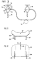
- FIGS. 11 and 12 show a seat cushion 201 with a single one on one side Stelliement 206 attacks.
- Actuator 206 from an eccentric drive in the left rear area of the Seat cushion 201.
- the seat cushion 201 has a rigid support structure 202 which extends over Springs 207 'with their rear attachment points 208 on two rear seat rail sections 210 and via a front connection point 211 at a middle one front seat rail section 212 is mounted.
- This "Three-point support" results from the illustrated one-sided adjustment movement Tilting of the seat cushion 201 by the eccentric drive 206 the tilt axis 207.
- FIG. 13 and 14 illustrate an inventive method for starting a geometric middle position in liquid-operated control elements, such as the actuators 86a and 86b of FIG. 7.
- Fig. 13 is the solid path s of the first actuating element with a solid line 86a plotted over time t. This is in phase opposition with the dashed Line indicated travel s of the second actuator 86b.
- Tilting movement of the seat cushion creates a movement of the lumbar sections the spine of a seated person.
- the individual phases of Tilting movement of the seat cushion about the tilt axis 7 is illustrated symbolically in FIG. 13.
- the actuating element 86a is first filled with liquid (filling time t F ) such that a central position M (half the maximum actuating travel) is established.
- the control element 86a is completely filled with the liquid (state V).
- the degree of filling is then reduced to such an extent that the middle position M is again set in order to subsequently return to the initial state L in the last section of the cycle.
- the filling and holding times t F and t H are the same in the selected example during the individual phases of the cycle and are constant over the cycle duration. For example, t F and t H are 10 seconds, so that the total cycle time is 80 seconds.
- Fig. 14 is the number N of the pump, for example a rotary vane pump 80, occurring impulses plotted over time t.
- pump 80 pumps the liquid from actuator 86a into the actuator 86b (solid line in the left part of the diagram), while in the in the second half of the cycle, the pumping direction is reversed (dashed line in the right part of the diagram).
- the factors F12 and F21 are made by the manufacturer does not determine and change over the life of the seating system noteworthy.
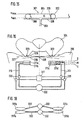
- FIG. 15 shows an actuating element 301 with flexible walls 302 (FIG. 15) and an air supply 303.
- the upper and lower walls 304 and 305 of the actuating element lie directly on top of one another.
- the pressurized state solid lines
- the two walls 304 and 305 are spaced apart from one another and form a bubble-shaped body.
- two webs 306 are provided, which are welded to the walls 304 and 305 of the control element 301.
- the webs 306 consist of a flexible but non-stretchable plastic material and form a path limitation in the direction of the travel s.
- a constant internal pressure p i is provided via the air supply 303, the force effect of which outweighs a maximum external weight load.
- the webs 306 limit the travel s to the value s max even at a lower load G.
- the depressurized state of the control element 301 represents the output path s min , the amount of which is determined by the wall thicknesses of the walls 304 and 305.
- the 16 are in a seat cushion 310 of a motor vehicle seat per seat half in each case two control elements 311a, b and 311c, d arranged one above the other.
- the individual adjusting elements 311a to 311d are comparable to the adjusting element 301 built up and via air supply 313 and valves 320 with a Pressure source 322 connected.
- the valves 320 are operated via a control device 321 controlled.
- the adjusting elements 311a to 311d are in the seat cushion 310, respectively beneath the seat bumps 323 of the pelvis 324, one seated on the seat cushion 310 Person arranged.
- the actuating elements 311a to 311d are either depressurized or acted upon by the operating pressure p i via the valves 320. Accordingly, the actuating elements 311a to 311d take up two exactly defined actuating heights s min or s max (analogously to FIG. 15).
- actuating heights s min or s max analogously to FIG. 15.
- the two dash-dotted lines 326 illustrate the two opposite maximum tilting positions of the pelvis 324, while the dashed line 327 represents the central position of the pelvis 324, in which only one actuating element 311a or 311b or 311c or 311d is pressurized on each side of the seat cushion.
- FIG. 18 shows an actuating device with two separate pressure sources 332, which supplies actuating elements 331a to 331d via air feeds 333.
- Each of the Pressure sources 332 each connect an adjusting element of one seat half to one Control element of the other half of the seat.
- the two pressure sources 332 work here in phase opposition, so that the adjusting elements 331a, b and 331c, d each have a seat half opposing pressure and a total tilting movement results as shown in Fig. 16.
Description
Die Erfindung bezieht sich auf einen Sitz nach dem Oberbegriff der Ansprüche 1
und 20 sowie auf ein Verfahren zur Ansteuerung eines Sitzes nach dem Oberbegriff
der Ansprüche 21 und 22. Als Sitze werden alle Arten von Sitzelementen mit einem
Sitzkissen und gegebenenfalls einer Rückenlehne bezeichnet, beispielsweise Bürostühle,
Fahrradsättel, Sitze in Kraftfahrzeugen, etc.The invention relates to a seat according to the preamble of
Aus der deutschen Patentanmeldung 195 47 964.5 ist ein Sitz bekannt, bei dem das Sitzkissen um seine Längs- oder Querachse verkippbar ist. Durch diese Kippbewegungen mit begrenzten kleinen Kippwinkeln werden das Becken einer sitzenden Person und damit die lumbalen Bewegungssegmente der Wirbelsäule bewegt. Auf diese Weise können auch während des ansonsten statischen Sitzvorgangs die Bandscheiben ausreichend Nährstoffe aufnehmen, so daß Rückenbeschwerden, hervorgerufen durch längeres Sitzen, minimiert werden. Zur Erzielung einer besseren Versorgung der Bandscheiben ist insbesondere eine seitliche Kippbewegung des Beckens besonders geeignet.From the German patent application 195 47 964.5 a seat is known in which the Seat cushion is tiltable about its longitudinal or transverse axis. Through these tipping movements with limited small tilt angles, the pelvis becomes a seated one Person and thus the lumbar movement segments of the spine moves. On in this way, even during the otherwise static sitting process Intervertebral discs absorb sufficient nutrients so that back problems, caused by prolonged sitting can be minimized. To achieve a better one Supply of the intervertebral discs is especially a lateral tilting movement of the pelvis particularly suitable.
Aus der DE 33 24 788 A1 ist ferner ein Bürostuhl bekannt, dessen Sitzkissen durch Stellelemente auf und ab bzw. hin und her bewegt werden kann.From DE 33 24 788 A1 an office chair is also known, the seat cushion by Control elements can be moved up and down or back and forth.
Aufgabe der Erfindung ist es, Wege aufzuzeigen, um die beschriebene Kippbewegung bei Sitzen, insbesondere Fahrzeugsitzen, zu erzeugen.The object of the invention is to show ways to the described tilting movement to produce seats, in particular vehicle seats.
Diese Aufgabe wird durch die Merkmale von Anspruch 1, 20, 21 oder 22 gelöst. This object is solved by the features of
Gemäß Anspruch 1 ist im Bereich des Sitzkissens wenigstens ein Paar von Stellelementen
vorgesehen. Diese beiden Stellelemente sind in einander gegenüberliegenden
Bereichen des Sitzkissens anzuordnen und so anzusteuern, daß sie eine
gegenläufige Hubbewegung zwischen einer unteren und einer oberen Position ausführen.
Durch die gegengleiche Aufwärts- und Abwärtsbewegung wird eine Kippbewegung
um eine Längs- oder Querachse des Sitzes erreicht. Dabei ist darauf zu
achten, daß die Kippachse möglichst nahe an den Sitzbeinhöckern der auf dem
Sitzkissen sitzenden Person liegt. Durch die Stellelemente darf nur eine reine Kippbewegung
erzeugt werden; eine Auf- und Abwärtsbewegung der sitzenden Person,
die eine nachhaltige Beeinträchtigung des Wohlbefindens zur Folge hätte, ist unbedingt
zu vermeiden.According to
Selbstverständlich kann in jeder seitlichen bzw. vorderen und hinteren Hälfte des Sitzkissens auch mehr als nur ein Stellelement vorgesehen werden. Bevorzugt werden die einander paarweise zugeordneten Stellelemente wechselseitig über einen gemeinsamen Antrieb angesteuert, wobei selbstverständlich auch die individuelle Ansteuerung eines jeden einzelnen Stellelements möglich ist.Of course, in each side or front and rear half of the Seat cushion more than just one control element can be provided. To be favoured the mutually assigned control elements alternately via one controlled common drive, of course also the individual Control of each individual control element is possible.
Die Ansprüche 2 bis 4 zeigen verschiedene Möglichkeiten der Anordnung der Stellelemente
auf.
Gemäß Anspruch 2 wird die gesamte Sitzfläche gekippt, was vor allem bei Sitzkonstruktionen
mit einer steifen Sitzschale umgesetzt werden kann.
Bei der Ausführung der Erfindung nach Anspruch 3 sind die Stellelemente zwischen
der Tragstruktur und dem Polsterteil angeordnet. Die Tragstruktur kann ihrerseits
befedert ausgebildet sein.
Bei einer Anordnung der Stellelemente unmittelbar im Polsterteil (Anspruch 4) sind
nur geringe Änderungen an der Tragstruktur des Sitzes erforderlich. Aufgrund des
geringen Abstandes der Stellelemente zu den Sitzhöckern der sitzenden Person
erfolgt eine direkte Übertragung der Kippbewegung. Auch können die Stellelemente
in direkter Linie unterhalb der Sitzbeinhöcker angeordnet werden. Durch die dazwischenliegende
Polsterschicht wird die Bewegung der Stellelemente geringfügig
abgefedert und somit die Kippbewegung zur Erhöhung des Sitzkomforts etwas
"verwaschen". Allgemein ist bei der Einbringung der Stellelemente darauf zu achten,
daß der Sitzkomfort durch die körpernah eingesetzten Stellelemente nur so wenig
als möglich beeinträchtigt wird.
According to
In the embodiment of the invention according to
If the adjusting elements are arranged directly in the upholstery part (claim 4), only minor changes to the supporting structure of the seat are required. Due to the small distance between the adjusting elements and the seat bumps of the seated person, the tilting movement is transmitted directly. The control elements can also be arranged in a direct line below the ischial humps. Due to the cushion layer in between, the movement of the adjusting elements is slightly cushioned and thus the tilting movement "washed out" to increase the seating comfort. In general, when installing the control elements, care must be taken to ensure that seating comfort is affected as little as possible by the control elements used close to the body.
Stellelemente gemäß Anspruch 5 sind besonders einfach im Aufbau und in der Anpassung
an den jeweiligen Anwendungsfall. Darüber hinaus sind sie kostengünstig
herzustellen. Als Stellelemente kommen beispielsweise Elemente mit flexiblen Wandungen
in Frage, z. B. Blasen oder Bälge aus einem gummielastischen Material.
Aufgrund der relativ großen einwirkenden Gewichtskräfte durch die sitzende Person
empfiehlt es sich, die Blasen, Bälge, etc. mit einer Gewebeeinlage zu verstärken. In
besonderer Weise sind Rollbälge geeignet, da sie ober- und unterseitig ebenflächige,
steife Begrenzungen zur Anbindung an die Sitzstruktur aufweisen. Gleichwirkend
zu den genannten Stellelementen können auch kurzhubige Zylinder mit starrer
Kammerwandung verwendet werden. Derartige Zylinder zeichnen sich durch einen
entsprechend großen Durchmesser bei kleinem Verstellweg aus und beanspruchen
somit einen Einbauraum, der im wesentlichen dem Platzbedarf balgartiger Stellelemente
entspricht.Adjusting elements according to
Die Stellelemente gemäß Anspruch 5 können mit Luft oder mit einer Flüssigkeit betrieben
werden.
Luftbefüllte Stellelemente sind insbesondere für eine Anordnung im Polsterteil des
Sitzkissens geeignet, da sie sich der Form der Sitzhöcker anpassen und nicht den
Eindruck einer harten Einlage vermitteln. Wegen der Druck- und Temperaturabhängigkeit
des Luftvolumens in den Stellelementen sind jedoch geeignete Maßnahmen
zur Regelung des Verstellweges der Stellelemente erforderlich, beispielsweise
mittels Wegmessung an den Stellelementen.
Bei Betrieb der Stellelemente mit einem flüssigen Medium kann aufgrund der Inkompressibilität
der Flüssigkeit ein definierter und reproduzierbarer Stellweg realisiert
werden, so daß die Steuerung oder Regelung der Stellweges über eine einfache
Messung des Volumenflusses zum und vom Stellelement erfolgen kann. Aufgrund
der Unnachgiebigkeit flüssigkeitsbefüllter Stellelemente ist jedoch eine Anordnung
unmittelbar in der Polsterung nahe den Sitzhöckern einer sitzenden Person
nur mit Einschränkungen möglich.The actuating elements according to
Air-filled adjusting elements are particularly suitable for an arrangement in the upholstered part of the seat cushion, since they adapt to the shape of the seat bumps and do not give the impression of a hard insert. Because of the pressure and temperature dependence of the air volume in the control elements, however, suitable measures for regulating the adjustment path of the control elements are required, for example by means of distance measurement on the control elements.
When the control elements are operated with a liquid medium, a defined and reproducible control path can be realized due to the incompressibility of the liquid, so that the control or regulation of the control path can be carried out via a simple measurement of the volume flow to and from the control element. Due to the intransigence of liquid-filled actuating elements, however, an arrangement directly in the upholstery near the seat bumps of a seated person is only possible with restrictions.
Gemäß Anspruch 6 wird das Medium für die Stellelemente in separaten Arbeitskammern
bereitgestellt. Mit der Überführung des Mediums aus der ersten Arbeitskammer
in das zugehörige Stellelement wird gleichzeitig das Medium aus dem anderen
Stellelement in die zweite Arbeitskammer abgezogen, so daß sich dererfindungsgemäße
Gegentakt selbsttätig einstellt. Die Entleerung desjenigen Stellelements,
das sich in seiner erhöhten Lage befindet, wird durch das Gewicht der sitzenden
Person unterstützt. Die Arbeitskammern sowie der Antrieb für die Volumenverschiebung
können in vorteilhafter Weise außerhalb des unmittelbaren Sitzbereiches
angeordnet sein, so daß innerhalb des Sitzes oder des Sitzkissens nur ein
geringer Bauraum benötigt wird.According to
Gemäß Anspruch 7 kann die Kippbewegung beispielsweise durch einen doppeltwirkenden pneumatischen oder hydraulischen Zylinder realisiert werden. Bei einem flüssigen Arbeitsmedium kann durch Messung des Kolbenweges ein definierter und reproduzierbarer Arbeitshub der Stellelemente erreicht werden. Anstelle der im Zylinder gebildeten Arbeitskammern können auch balgförmige Arbeitskammern (Anspruch 8) vorgesehen sein.According to claim 7, the tilting movement, for example, by a double-acting pneumatic or hydraulic cylinders can be realized. At a liquid working medium can be defined and measured by measuring the piston stroke reproducible working stroke of the control elements can be achieved. Instead of the one in the cylinder Working chambers formed can also be bellows-shaped working chambers (Claim 8) may be provided.
Die Weiterbildung der Erfindung nach Anspruch 9 verzichtet auf eigene Arbeitskammern für das Medium. Hierdurch ergibt sich ein besonders einfacher Aufbau bei gleichzeitig sehr geringem Bauraumbedarf. Das Medium wird unmittelbar zwischen den beiden Stellelementen hin- und hergepumpt, ohne ein separates Reservoir, aus dem das Medium entnommen bzw. in das das Medium zurückgeführt wird. Somit ergibt sich ein "geschlossenes Pendelsystem" mit einer besonders geringen Füllmenge an Medium.The development of the invention according to claim 9 dispenses with its own working chambers for the medium. This results in a particularly simple construction at the same time, very little space is required. The medium is immediately between the two control elements pumped back and forth without a separate reservoir from which the medium is removed or into which the medium is returned. Consequently the result is a "closed pendulum system" with a particularly small filling quantity of medium.
Als Druckmittelpumpen kommen generell alle bekannten Ausführungsformen von Pumpen in Frage. Bei Einsatz einer Drehschieberpumpe (Anspruch 10) ergibt sich in Verbindung mit einem flüssigen Medium der Vorteil, daß pro Umdrehung der Pumpe ein meßbares und weitgehend gleichbleibendes Volumen gefördert wird. Durch Erfassung der Drehzahl der Pumpe können die Stellelemente in einfacher Weise angesteuert oder geregelt werden. Auch ist das Anfahren einer gleichbleibenden Mittellage der Stellelementen ohne weiteres möglich. Durch entsprechende Regelung der Drehzahl der Pumpe kann der Verlauf der Stellbewegung über der Zeit beeinflußt werden.All known embodiments of come generally as pressure medium pumps Pumps in question. When using a rotary vane pump (claim 10) results in connection with a liquid medium the advantage that the Pump a measurable and largely constant volume is promoted. By detecting the speed of the pump, the control elements can be more easily Be controlled or regulated. The start is also a constant one Middle position of the control elements is easily possible. By appropriate Regulating the speed of the pump can change the course of the actuating movement over the Time will be affected.
Grundsätzlich kann anstelle einer Drehschieberpumpe auch eine Kolbenpumpe eingesetzt werden, die bei Einsatz eines flüssigen Mediums ebenfalls einen meßbaren Volumenstrom fördert. Aufgrund der auftretenden Pulsationen ist die Anwendung von Kolbenpumpen auf kleinere Einzelvolumina beschränkt. Gegebenenfalls sind Mehrkolbenpumpen einzusetzen.In principle, a piston pump can also be used instead of a rotary vane pump be, which are also measurable when using a liquid medium Volume flow promotes. The application is due to the pulsations that occur of piston pumps limited to smaller individual volumes. Where applicable Use multi-piston pumps.
In weiterer Ausgestaltung der Erfindung sind gemäß Anspruch 11 an zwei gegenüberliegenden Bereichen des Sitzkissens jeweils wenigstens zwei Stellelemente übereinander angeordnet, wobei jedes der Stellelemente einen festgelegten Verstellweg zwischen den beiden definierten und reproduzierbaren Zuständen "Stellelement vollständig entleert" und "Stellelement vollständig befüllt" ausführen kann. Durch entsprechende Befüllung oder Entleerung der einzelnen Stellelemente können somit stufenförmig verschiedene Stellhöhen angefahren werden. Dies ist erfindungsgemäß ohne Wegmessung, die eine Sensorik erfordern würde, mit besonders geringem Aufwand möglich, beispielsweise mit einer einfachen Steuerung über Ventile, die lediglich die beiden Zustände "drucklos" bzw. "voller Betriebsdruck" erzeugen. Die Anzahl der übereinander angeordneten Stellelemente bestimmt die Anzahl der möglichen Stellpositionen.In a further embodiment of the invention are according to claim 11 on two opposite Areas of the seat cushion at least two control elements arranged one above the other, each of the adjusting elements having a fixed adjustment path between the two defined and reproducible states Execute "control element completely empty" and "control element completely filled" can. By filling or emptying the individual control elements accordingly can be approached in different stages. This is according to the invention without path measurement, which would require a sensor system, with in particular little effort possible, for example with a simple control via valves that only have the two states "depressurized" or "full operating pressure" produce. The number of control elements arranged one above the other determines the Number of possible positions.
Als Stellelemente kommen bevorzugt Elemente mit flexiblen Wandungen in Frage, z. B. Blasen oder Bälge aus einem gummielastischen Material. Aufgrund der relativ großen einwirkenden Gewichtskräfte durch die sitzende Person empfiehlt es sich, die Blasen, Bälge, etc. mit einer Gewebeeinlage zu verstärken. Bei Verwendung blasenartiger Stellelemente ergibt sich ein sehr geringer Platzbedarf, da die Bauhöhe der Stellelemente im Ausgangszustand lediglich durch die Summe ihrer Wanddicken bestimmt wird. In besonderer Weise sind auch Rollbälge geeignet, da sie ober- und unterseitig ebenflächige, steife Begrenzungen zur Anbindung an die Sitzstruktur aufweisen. Gleichwirkend zu den genannten Stellelementen können auch kurzhubige Zylinder mit starrer Kammerwandung verwendet werden. Derartige Zylinder zeichnen sich durch einen entsprechend großen Durchmesser bei kleinem Verstellweg aus und beanspruchen somit einen Einbauraum, der im wesentlichen dem Platzbedarf balgartiger Stellelemente entspricht.Elements with flexible walls are preferred as adjusting elements, e.g. B. bubbles or bellows made of a rubber-elastic material. Because of the relative large acting weight forces by the seated person it is recommended reinforce the bladders, bellows, etc. with a fabric insert. Using bubble-like control elements result in a very small space requirement, since the overall height the control elements in the initial state only by the sum of their Wall thickness is determined. Rolled bellows are also particularly suitable because they have flat, rigid boundaries on the top and bottom for connection to the Have seat structure. Can have the same effect on the control elements mentioned short-stroke cylinders with rigid chamber walls can also be used. Such Cylinders are characterized by a correspondingly large diameter with a small one Adjustment path and thus take up an installation space that is essentially corresponds to the space required for bellows-type control elements.
Bei zwei übereinander angeordneten Stellelementen ergeben sich drei definierte Stellhöhen: Der drucklose Zustand beider Stellelemente markiert die untere Stellung, deren Bauhöhe zum Beispiel bei blasenartigen Stellelementen allein durch die Summe der Wanddicken der beiden Blasen bestimmt wird. Eine mittlere Position ergibt sich durch Druckbeaufschlagung eines der beiden Stellelemente, während das zweite Stellelement drucklos bleibt. Schließlich kann die obere Position durch Druckbeaufschlagung beider Stellelemente definiert angefahren werden. Werden die beiden Stellelemente gleichartig ausgeführt, kann eine mittlere Position angefahren werden, die exakt in der geometrischen Mitte zwischen unterer und oberer Position liegt. Durch eine abwechselnd gegensinnige Ansteuerung der paarweise angeordneten Stellelemente in den beiden Sitzkissenbereichen wird eine Verkippung des Beckens um die Längs- oder Querachse des Sitzes erzielt, wie in Anspruch 22 beschrieben. Selbstverständlich umfaßt die beanspruchte Ansteuerung sinngemäß auch Ausführungsformen mit mehr als zwei übereinander angeordneten Stellelementen.With two control elements arranged one above the other, there are three defined ones Adjustment heights: The depressurized state of both control elements marks the lower position, whose overall height, for example, in the case of bubble-like control elements, is achieved solely by Sum of the wall thicknesses of the two bubbles is determined. A middle position results from pressurization of one of the two control elements while the second control element remains depressurized. Finally, the top position can go through Pressurization of both control elements can be started in a defined manner. Become the two control elements are designed in the same way, a middle position can be reached be exactly in the geometric center between the lower and upper position lies. By alternately controlling the pairs arranged in opposite directions Adjustment elements in the two seat cushion areas will tilt the Achieves pelvis about the longitudinal or transverse axis of the seat, as described in claim 22. Of course, the claimed control includes the same also embodiments with more than two arranged one above the other Control elements.
Bei flüssigkeitsbefüllten Stellelementen ist der Stellweg - entsprechende Gestaltung des Stellelementes vorausgesetzt - weitestgehend unabhängig von der Belastung des Stellelements und der Umgebungstemperatur. Somit lassen sich in besonders einfacher Weise reproduzierbare Stellwege erzielen.In the case of liquid-filled control elements, the travel is appropriate of the control element - largely independent of the load of the control element and the ambient temperature. Thus, in particular easily achieve reproducible travel.
Pneumatische Stellelemente hingegen sind in der Regel einfacher aufgebaut und
einfacher anzusteuern als flüssigkeitsbefüllte Stelletemente. Aufgrund der Kompressibilität
des gasförmigen Mediums und dessen starker Temperaturabhängigkeit
ist der (maximale) Stellweg jedoch nicht reproduzierbar. Daher wird gemäß Anspruch
12 vorgeschlagen, durch eine zusätzliche Einrichtung am Stellelement dessen
Verstellweg selbsttätig zu begrenzen. Somit wird, unabhängig von der Belastung
des pneumatischen Stellelements, jeweils ein definierter maximaler Stellweg
eingehalten, sofern das Stellelement mit einem Innendruck beaufschlagt wird, der
größer ist, als es aufgrund der wirksamen Innenfläche des Stellelements und der
jeweiligen Belastung durch eine sitzende Person notwendig wäre. Damit ist sichergestellt,
daß ohne zusätzlichen Maßnahmen, wie beispielsweise eine Wegmessung,
ein konstanter Verstellweg eingehalten wird.Pneumatic control elements, on the other hand, are generally of a simpler structure and
easier to control than liquid-filled actuators. Because of the compressibility
of the gaseous medium and its strong temperature dependence
however, the (maximum) travel is not reproducible. Therefore, according to
So sind gemäß Anspruch 13 Wegbegrenzungen im Inneren des Stellelements vorgesehen. Diese Wegbegrenzungen bestehen bevorzugt aus einem flexiblen, nicht dehnbarem Material. Sie können bei Stellelementen mit Wandungen aus einem Kunststoffmaterial bei der Herstellung unmittelbar mit dem Stellelement verschweißt werden. Hierdurch ergibt sich ein besonders einfacher Aufbau und eine kostengünstige Herstellung.Thus, path limits are provided in the interior of the actuating element. These path limitations preferably consist of a flexible, not stretchy material. You can use control elements with walls made of one Plastic material welded directly to the actuator during manufacture become. This results in a particularly simple structure and an inexpensive one Manufacturing.
Alternativ können die - in Verstellrichtung betrachtet - gegenüberliegenden Wandabschnitte bei Stellelementen aus einem Kunststoffmaterial abschnittsweise miteinander verschweißt werden, so daß sich durch diese Verschweißungen ebenfalls eine Wegbegrenzung ergibt (vergleichbar den Absteppungen beispielsweise bei Luftmatratzen). Daneben sind selbstverständlich auch außenliegende Wegbegrenzungen möglich, wobei die teilweise oder umlaufend ringförmige Umschlingung des Stellelements beispielsweise durch Bänder aus flexiblem und nicht dehnbarem Material erfolgt. Bevorzugt wird die Wegbegrenzung am Außenumfang des Stellelements zusätzlich fixiert, um ein Abrutschen im drucklosen Zustand des Stellelements zuverlässig zu verhindern.Alternatively, the wall sections - viewed in the adjustment direction - can be opposite with control elements made of a plastic material in sections with each other are welded so that there is also a through these welds Path limitation results (comparable to the stitching, for example with air mattresses). In addition, of course, there are external path limits possible, the partially or circumferentially annular wrapping of the actuating element for example, with tapes made of flexible and non-stretch material he follows. The path limitation on the outer circumference of the actuating element is preferred additionally fixed to reliably prevent the actuator from slipping when depressurized to prevent.
Entscheidend ist bei Einsatz eines gasförmigen Druckmittels zum Betrieb derStellelemente, daß ein ausreichend hoher Druck zur Verfügung steht, um in Verbindung mit der erfindungsgemäßen Wegbegrenzung unabhängig von der Belastung durch die sitzende Person jeweils konstante Stellwege und damit definierte, begrenzte Kippwinkel zuverlässig einhalten zu können. Die Ansteuerung der Stellelemente kann über einfach aufgebaute Ventile erfolgen. Eine Sensorik zur Auswertung der jeweils vorliegenden Stellhöhe ist nicht erforderlich. Außerdem ist bei mehreren Sitzen, beispielsweise in einem Fahrzeug, eine zentrale Luftversorgung mit einer einzigen Druckquelle ausreichend.It is crucial when using a gaseous pressure medium to operate the control elements, that a sufficiently high pressure is available to connect with the path limitation according to the invention regardless of the load the seated person has constant travel ranges and thus defined, limited To be able to reliably maintain the tilt angle. The control of the control elements can be done with simple valves. A sensor system for evaluating the the respective standing height is not necessary. In addition, with multiple seats, for example in a vehicle, a central air supply with a single Sufficient pressure source.
In weiterer Ausgestaltung der Erfindung kann gemäß Anspruch 14 zwischen den Stellelementen beispielsweise der beiden Sitzhälften ein Absperrventil vorgesehen sein, durch das ein Austausch des Mediums zwischen den Stellelementen zuverlässig verhindert wird. Eine Aktivierung des Absperrventils erfolgt durch den Benutzer, wenn die Einrichtung zur Erzeugung einer Kippbewegung abgeschaltet ist und das Sitzkissen in einer "schiefen" Lage fixiert werden soll, indem die Stellelemente in unterschiedlicher Höhenposition "arretiert" werden. Durch das Absperrventil wird ein langsames Überströmen des Mediums, z. B. durch Leckverluste in einer Pumpe, verhindert. Eine derartige Anwendung kommt beispielsweise für Sitzbenutzer in Betracht, die aus orthopädischen Gründen eine Schiefstellung des Sitzkissens benötigen.In a further embodiment of the invention can according to claim 14 between the Control elements, for example, the two seat halves provided a shut-off valve be reliable, through which an exchange of the medium between the control elements is prevented. The shut-off valve is activated by the user, if the device for generating a tilting movement is switched off and that Seat cushions should be fixed in an "oblique" position by using the adjusting elements in different height positions can be "locked". The shut-off valve turns on slow overflow of the medium, e.g. B. due to leakage in a pump, prevented. Such an application is considered, for example, for seat users, who, for orthopedic reasons, need to tilt the seat cushion.
Die Ansprüche 15 bis 19 zeigen beispielhaft weitere grundsätzliche Wirkprinzipien
von Stellelementen auf. Die genannten Wirkprinzipien können durch einen motorischen
Stellantrieb, beispielsweise einen Elektromotor oder aber auch mit einem
Druckmittel umgesetzt werden. Insbesondere Elektromotoren zeichnen sich durch
geringen Bauraumbedarf und ihre einfache Ansteuerbarkeit aus. Die motorischen
Stellantriebe können mit allen bekannten Übertragungselementen kombiniert werden,
beispielsweise mit rotatorischen oder linearen Getrieben, Exzentern, Zahnstangen,
etc. Bei Druckmittelantrieb werden aufgrund der besseren Regelungsmöglichkeiten
und der höheren Arbeitsdrücke hydraulische Medien bevorzugt.
Die direkte Umsetzung der Stellbewegung über Hebelarme (Anspruch 15) erfordert in den meisten Fällen ein Getriebe zur Kraftübersetzung, wobei sowohl rotatorische als auch lineare Getriebe, je nach Art der Krafterzeugung, denkbar sind. The direct implementation of the actuating movement via lever arms (claim 15) requires in most cases a gearbox for power transmission, both rotary as well as linear gears, depending on the type of force generation, are conceivable.
Spindeltriebe gemäß Anspruch 16 werden von einem Drehmotor angetrieben und
wandeln dessen Rotationsbewegung in eine Vertikalbewegung um. Bevorzugt ist
eine gemeinsame Antriebswelle für die paarweise angeordneten Stellelemente vorzusehen.
Sinngemäß gilt dies auch für Exzenterantriebe gemäß Anspruch 17 und
Hubgestänge gemäß Anspruch 18.Spindle drives according to claim 16 are driven by a rotary motor and
convert its rotational movement into a vertical movement. Is preferred
to provide a common drive shaft for the adjusting elements arranged in pairs.
This applies analogously to eccentric drives according to
Durch keilförmige Elemente (Anspruch 19), insbesondere keilförmige Scheiben, die gegeneinander verdreht werden, können Höhenänderungen im Bereich der Sitzhöcker der sitzenden Person erreicht werden. Die Keilscheiben können hierbei zur Verringerung der Reibung über Wälzkörper gegeneinander gelagert sein.By wedge-shaped elements (claim 19), in particular wedge-shaped disks, the can be rotated against each other, height changes in the area of the seat bumps the seated person can be reached. The wedge disks can be used Reduction of the friction on rolling elements against each other.
Gemäß Anspruch 20 wird die Verkippung des Sitzkissens durch ein einseitig angreifendes Stellelement realisiert. Diese Verkippung bietet sich insbesondere bei solchen Sitzen an, deren Sitzkissen eine starre "Sitzwanne" aufweist, die als Ganzes um eine vorgegebene Mittelachse verkippbar ist. Die Verkippung über ein einseitig angreifendes Stellelement läßt sich aber auch bei Sitzen mit einem Federkern-Unterbau anwenden, wobei sich in diesem Fall selbsttätig eine Kippachse etwa in der Mitte des Sitzkissens einstellt. Das Stellelement ist bevorzugt außerhalb der Tragstruktur des Sitzkissens angeordnet. Auch eine Anordnung des Stellelements zwischen Tragstruktur und Polsterteil ist möglich. Als Stellelemente kommen beispielsweise grundsätzlich alle oben angegebenen Ausführungsformen in Frage.According to claim 20, the tilt of the seat cushion by a one-sided attack Control element realized. This tilt is particularly useful for such seats, the seat cushion of which has a rigid "seat pan", as a whole is tiltable about a predetermined central axis. Tilting over one sided Attacking actuator can also be found in seats with a spring core substructure apply, in which case a tilt axis automatically in the middle of the seat cushion. The actuator is preferably outside of the Support structure of the seat cushion arranged. Also an arrangement of the control element between the supporting structure and the upholstered part is possible. As control elements come for example basically all the above-mentioned embodiments in question.
Wie bereits angesprochen, ergeben sich beim Betrieb der Stellelemente mit einem
flüssigen Medium Vorteile hinsichtlich der Steuerung oder Regelung des Stellweges,
da über die Messung des Volumenflusses ein definierter Stellweg erreicht werden
kann.
Anspruch 21 beschreibt ein Verfahren, mit dem, unabhängig von der Sitzposition
oder dem Körpergewicht des Sitzbenutzers, eine jeweils gleichbleibende Mittellage
für ein blasenartiges Stellelement (gemäß Anspruch 5) erreicht werden kann.
Bestimmte Bauarten von Pumpen (z. B. Drehschieberpumpen) geben mit jeder Umdrehung
eine festgelegte Anzahl meßbarer Impulse ab, mit einem linearen Zusammenhang
zwischen der Impulsanzahl und der geförderten Flüssigkeitsmenge. Der
geförderte Flüssigkeitsstrom ist jedoch innerhalb bestimmter Grenzen abhängig von
verschiedenen Parametern, z. B. Antriebsrichtung der Pumpe, Pump- oder Saugbetrieb,
Höhe des Druckes, gegen den gefördert oder mit dem abgesaugt wird, etc.As already mentioned, there are advantages with regard to the control or regulation of the travel when operating the control elements with a liquid medium, since a defined travel can be achieved by measuring the volume flow.
Certain types of pumps (e.g. rotary vane pumps) emit a fixed number of measurable pulses with each revolution, with a linear relationship between the number of pulses and the amount of liquid delivered. The fluid flow delivered is, however, dependent on various parameters, e.g. B. Drive direction of the pump, pumping or suction operation, level of pressure against which the pumping or suction is carried out, etc.
Bei dem erfindungsgemäßen Verfahren wird in einem geschlossenen System, in
dem die Pumpe ein vorgegebenes Flüssigkeitsvolumen zwischen zwei Stellelementen
1 und 2 hin- und herbefördert, zunächst ein Ausgangszustand definiert, bei dem
eines der Stellelemente (z. B. das Stellelement 1) gerade vollständig entleert ist.
Dieser Zustand ist anhand des bei entleertem Stellelement auftretenden steilen
Druckabfalls in der Pumpe eindeutig zu bestimmen und wird nachfolgend als Anfangswert
L12 bezeichnet, mit L = "Stellelement leer" und 12 = "Pumprichtung vom
Stellelement 1 in das Stellelement 2". Nachfolgend fördert die Pumpe die Flüssigkeit
in das zuvor entleerte Stellelement 2 zurück, bis eine fiktive Mittellage des
Stellelements 2 (und damit auch des Stellelements 1) erreicht ist. Hierbei wird die
Pumpe mit einer Impulszahl angesteuert, die auf einem Voreinstellwert basiert, so
daß für den ersten Zyklus nach der Inbetriebnahme des Systems unter Umständen
zunächst noch eine unrichtige ("schiefe") Mittellage erzeugt wird. Anschließend wird
das Stellelement 2 vollständig befüllt, wobei als Maß für die vollständige Füllung der
Druckabfall im nunmehr vollständig entleerten Stellelement 1 herangezogen wird
(Endwert V12 mit V = "Stellelement voll"). Die Anzahl der von der Pumpe gelieferten
Impulse N12 zwischen den beiden Werten L12 und V12 wird in einem Datenspeicher
abgelegt.In the method according to the invention, in a closed system, in
which the pump a predetermined volume of liquid between two
In gleicher Weise wird für die umgekehrte Pumprichtung vom Stellelement 2 in das
Stellelement 1 der Endwert V21 ermittelt. Ausgangspunkt für diese Zählung ist der
Anfangswert L21 (entspricht dem Wert V12). Somit erhält man für die zweitePumprichtung
eine Impulsanzahl N21.In the same way for the reverse pumping direction from the
Nach dem ersten vollständigen Zyklus stehen nunmehr mit N12 und N21 Maßzahlen zur Verfügung, die angeben, wie viele Impulse jeweils für das vollständige Umpumpen der Flüssigkeit zwischen den beiden Stellelementen erforderlich sind. Die Maßzahlen N12 und N21 werden mit zuvor empirisch ermittelten Faktoren F12 und F21 multipliziert. Die Faktoren F12 und F21 sind für eine bestimmte ausgeführte Einheit aus Sitz und Stellelementen gleichbleibend. Da die Faktoren F12 und F21 in der Regel nur geringfügig voneinander abweichen, kann für die beiden Pumprichtungen vereinfachend auch mit einem einheitlichen Faktor F gearbeitet werden.After the first complete cycle there are now figures with N12 and N21 available, which indicate how many pulses each for the complete pumping the liquid between the two control elements are required. The Dimensional figures N12 and N21 are calculated with previously empirically determined factors F12 and F21 multiplied. The factors F12 and F21 are executed for a particular one Consistent unit of seat and control elements. Since the factors F12 and F21 in usually differ only slightly from each other, can be for the two pump directions to simplify work with a uniform factor F.
Durch das Produkt F12·N12 bzw. F21·N21 wird im nachfolgenden Zyklus die exakte geometrische Mittellage der beiden Stellelemente angefahren. Bemerkenswert ist hierbei, daß dieses Anfahren der Mittellage ohne direkte Wegmessung erfolgen kann, so daß sich das erfindungsgemäße Verfahren durch einen sehr geringen Aufwand auszeichnet. Durch die Maßzahlen N12 und N21 wird die jeweilige Belastung des Sitzes durch den Insassen berücksichtigt, so daß bereits nach einem einzigen Initialisierungszyklus, in dem die Werte N12 und N21 ermittelt werden, die geometrische Mittellage der Stellelemente exakt eingehalten wird.With the product F12 · N12 or F21 · N21 in the following cycle exact geometric center position of the two control elements. Remarkable is that this approach to the middle position is done without direct distance measurement can, so that the inventive method is characterized by a very low Outstanding effort. The respective figures are given by the dimension numbers N12 and N21 Load of the seat by the occupant is taken into account, so that after one single initialization cycle in which the values N12 and N21 are determined geometric center position of the control elements is exactly adhered to.
Die Sitzbelastung wird maßgeblich vom Körpergewicht des Sitzbenutzers und der Kontaktfläche zwischen dem Sitzbenutzer und dem Sitzkissen bestimmt. Daneben beeinflußt auch die Sitzposition des Sitzbenutzers die Werte N12 und N21, je nach dem, ob die rechte oder linke bzw. die vordere oder hintere Sitzhälfte stärker belastet werden. Damit stellt sich gemäß dem erfindungsgemäßen Verfahren das System nicht nur auf unterschiedliche Sitzbenutzer, sondern auch dynamisch auf wechselnde Sitzpositionen ein- und desselben Sitzbenutzers ein.The seat load is largely determined by the body weight of the seat user and the Contact area between the seat user and the seat cushion determined. Besides The seating position of the seat user also influences the values N12 and N21, depending on whether the right or left or the front or rear half of the seat is heavier become. The system thus arises according to the method according to the invention not only to different seat users, but also dynamically changing seating positions of the same seat user.
Mögliche Ausführungsbeispiele der Erfindung sind in der Zeichnung schematisch dargestellt und nachfolgend näher beschrieben. Es zeigt:
- Fig. 1
- ein Sitzkissen mit außerhalb der Tragstruktur angeordneten Stellelementen,
- Fig. 2
- ein Sitzkissen mit Stellelementen zwischen der Tragstruktur und dem Polsterteil,
- Fig. 3
- ein Sitzkissen mit in das Polsterteil eingesetzten Stellelementen,
- Fig. 4 bis 7
- Ausführungsbeispiele fluidbetriebener Stellelemente,
- Fig. 8 bis 10
- Ausführungsbeispiele "mechanisch" angetriebener Stellelemente,
- Fig. 11, 12
- eine Anordnung eines einzelnen Stellelementes an einem Sitzkissen,
- Fig. 13, 14
- Diagramme zur Veranschaulichung der Ermittlung der Werte N12 und N21 zum korrekten Anfahren der Mittellage flüssigkeitsbefüllter Stellelemente,
- Fig. 15
- eine schematische Darstellung eines weiteren erfindungsgemäßen Stellelements,
- Fig. 16
- eine Anordnung erfindungsgemäßer Stellelemente gemäß Fig. 15 in einem Kraftfahrzeugsitz,
- Fig. 17
- ein tabellarisches Ansteuerungsschema für eine Anordnung von Stellelementen gemäß Fig. 16 und
- Fig. 18
- eine der Fig. 16 entsprechende Anordnung mit zwei Druckquellen.
- Fig. 1
- a seat cushion with adjusting elements arranged outside the supporting structure,
- Fig. 2
- a seat cushion with adjusting elements between the support structure and the upholstered part,
- Fig. 3
- a seat cushion with control elements inserted into the upholstery,
- 4 to 7
- Examples of fluid-operated control elements,
- 8 to 10
- Embodiments of "mechanically" driven actuators,
- 11, 12
- an arrangement of a single control element on a seat cushion,
- 13, 14
- Diagrams to illustrate the determination of the values N12 and N21 for the correct approach to the middle position of liquid-filled control elements,
- Fig. 15
- 2 shows a schematic representation of a further control element according to the invention,
- Fig. 16
- 15 an arrangement of control elements according to the invention as shown in FIG. 15 in a motor vehicle seat,
- Fig. 17
- a tabular control scheme for an arrangement of actuators according to FIGS. 16 and
- Fig. 18
- an arrangement corresponding to FIG. 16 with two pressure sources.
Fig. 1 zeigt ein Sitzkissen 1, das sich aus einer Tragstruktur 2 und einem Polsterteil
3 zusammensetzt. Der mittlere Teil des Sitzkissens 1 ist als Sitzfläche 4 ausgebildet,
während die seitlichen Bereiche 5 wuistförmig gestaltet sind. An der Unterseite der
Tragstruktur 2 greifen rechts und links jeweils außenliegend Stellelemente 6 an, die
eine Mittellage M sowie eine obere und eine untere Position O bzw. U einnehmen
können. Da die Tragstruktur 2 gegenüber einem nicht dargestellten Sitzrahmen oder
einer Sitzaufhängung innerhalb bestimmter Grenzen federnd gelagert ist
(Aufhängung 8), wird bei einer gegensinnigen Bewegung der rechten und linken
Stellelemente 6 eine Kippbewegung des Sitzkissens um eine Kippachse 7 erzeugt,
die in der Längsmittenebene 9 des Sitzkissens 1 liegt.Fig. 1 shows a
Fig. 2 zeigt ein Sitzkissen 11, bei dem die Stellelemente 16 zwischen der
Tragstruktur 12 und dem Polsterteil 13 angeordnet sind. Hierfür eignen sich vor allem
flachbauende Stellelemente 16. Die einzelnen Positionen, die die Stellelemente
16 einnehmen können, sind wiederum mit M, O und U bezeichnet. Übergangsbereiche
18 zwischen den relativ starr an die Tragstruktur 12 angebundenen Wülsten
15 und der Sitzfläche 14 ermöglichen einen Ausgleich der durch die Stellelemente
16 hervorgerufenen Kippbewegungen. Die Tragstruktur 12 kann ihrerseits befedert
sein, wie in Fig. 2 anhand der gestrichelt dargestellten Federn 17 veranschaulicht.Fig. 2 shows a seat cushion 11, in which the adjusting
Fig. 3 zeigt eine weitere Möglichkeit der Einbringung von Stellelementen 26 in ein
Sitzkissen 21, das sich wiederum aus einer Tragstruktur (nicht dargestellt) und
einem Polsterteil 23 zusammensetzt. Die Stellelemente 26 sind bevorzugt als luftgefüllte
Blasen oder flachbauende Rollbälge ausgeführt. Sie können in das Polsterteil
eingelegt oder eingeklebt oder auch vom Material des Polsterteils 23umschäumt
sein.3 shows a further possibility of introducing
Die Fig. 4 bis 7 zeigen verschieden Möglichkeiten des Antriebs von Stellelementen über ein flüssiges oder gasförmiges Medium.4 to 7 show different ways of driving actuating elements via a liquid or gaseous medium.
In Fig. 4 ist ein doppeltwirkender Zylinder 40 dargestellt, der über Verbindungsleitungen
41 Stellelemente 46a und 46b ansteuert. Der Zylinder weist eine erste und
eine zweite Arbeitskammer 42 bzw. 43 auf, die durch einen Kolben 44 voneinander
getrennt sind. Über eine Kolbenstange 45 kann der Kolben verschoben werden,
wobei sich die Volumina der beiden Arbeitskammern 42 bzw. 43 in gegensinniger
Weise vergrößern bzw. verkleinern. Eine zweite Kolbenstange 47 stellt die Volumengleichheit
in den beiden Arbeitskammern 42 und 43 sicher. Mit der linearen Bewegung
des Kolbens 44 (Weg s) wird der Füllgrad des linken bzw. rechten Stellelements
46a, 46b ebenfalls kontinuierlich verändert. In Fig. 4, a double-acting
Als Stellelemente 46a und 46b sind beispielhaft links und rechts unterschiedliche
Ausführungsformen dargestellt, wobei bei einer ausgeführten Anlage selbstverständlich
beidseitig identische Stellelemente vorzusehen sind. Das Stellelement 46a
ist als blasenförmiges Gebilde mit allseitig flexiblen Wandungen 48 ausgebildet,
während das Stellelement 46b von einem rollbalgartigen Gebilde mit einer oberen
und einer unteren Deckplatte 49 bzw. 50 sowie einem gummielastischen Rollbalg 51
gebildet wird.
Im Ausführungsbeispiel der Fig. 5 sind die Arbeitskammern 62 und 63 in einem Gehäuse
60 aufgenommen und werden von Blasen oder Rollbälgen gebildet, die über
Verbindungsleitungen 61 an nicht dargestellte Stellelemente angeschlossen sind.
Das Gehäuse 60 führt einen Schieber 64, der parallel zu den seitlichen Begrenzungswänden
65 des Gehäuses 60 verschoben werden kann (Weg s).5, the working
Bei der alternativen Ausführungsform gemäß Fig. 6 sind die beiden Arbeitskammern
72 und 73 in einem im Querschnitt etwa V-förmigen Gehäuse 70 angeordnet. Eine
Schwenkplatte 74 ist an der Schnittlinie der beiden Begrenzungswände 75 des
Gehäuses 70 schwenkbar gelagert (Schwenkachse 71), so daß die Platte 74 bei
einer Krafteinleitung z. B. am Angriffspunkt 77 oder einer Drehmomenteinleitung an
der Schwenkachse 71 verstellt werden kann (Schwenkwinkel α).In the alternative embodiment according to FIG. 6, the two working
Die Stellelemente gemäß der Fig. 4 bis 6 werden über voneinander getrennte Fluidkreise
jeweils gegengleich verstellt. Die Verstellung kann beispielsweise über einen
hin- und hergehenden Linearantrieb, einen Exzenterantrieb, etc. erfolgen. Bei Einsatz
flüssiger Medien werden belastungsunabhängig nahezu gleichbleibende Stellwege
an den Stellelementen erreicht. In allen Fällen ist ein Reservoir
(Arbeitskammern 42, 43 bzw. 62, 63 bzw. 72, 73) vorgesehen, über das die zugehörigen
Stellelemente befüllt bzw. entleert werden.The adjusting elements according to FIGS. 4 to 6 are via separate fluid circuits
adjusted in opposite directions. The adjustment can be made, for example, via a
reciprocating linear drive, an eccentric drive, etc. take place. When in use
liquid media become almost constant travel ranges regardless of load
reached on the control elements. In all cases there is a reservoir
(Working
Im Unterschied hierzu sind die Stellelemente 86a und 86b gemäß Fig. 7 über eine
Drehschieberpumpe 80 unmittelbar miteinander verbunden und werden gegensinnig
mit Druck beaufschlagt. Die Drehschieberpumpe 80 weist mehrere Kammern 81 auf,
die ein definiertes Kammervolumen fördern. Die einzelnen Kammern 81 sind über
radial bewegliche Schieber 82 voneinander getrennt und gegenüber dem Pumpengehäuse
83 abgedichtet. Durch die in Fig. 7 gezeigte Anordnung kann auf separate
Kammern zur Bereitstellung des Arbeitsmediums verzichtet werden, wodurch
sich eine besonders kompakte Bauweise ergibt. Die Drehschieberpumpe 80 kann
beispielsweise von einem Elektromotor angetrieben werden, dessen Drehzahl über
einen Hallsensor erfaßt wird, so daß bei Förderung flüssiger Medien der Stellweg an
den Stellelementen 86a und 86b in einfacher Weise gesteuert oder geregelt werden
kann.In contrast to this, the adjusting
In einer der Verbindungsleitungen 88 ist ein in beiden Strömungsrichtungen wirkendes
Absperrventil 89 vorgesehen, mit dem ein Austausch des Mediums zwischen
den beiden Stellelementen 86a und 86b unterbunden werden kann, um eine statische
"Schiefstellung" des Sitzkissens des Fahrzeugsitzes zu erzielen. Die Schiefstellung
wird beispielsweise dadurch erreicht, daß das im stromlosen Zustand sperrende
Ventil 89 kurzzeitig bestromt wird, so daß über die Leckspalte der Drehschieberpumpe
80 unter der Gewichtskraft und ggf. einer bewußt beeinflußten Gewichtsverteilung
des Sitzbenutzers ein Leckstrom fließt und sich die gewünschte
Schieflage einstellt.In one of the connecting
Fig. 8 zeigt Stellelemente 96, die jeweils eine Spindelmutter 91 und eine Spindel 92
aufweisen. Beide Stellelemente 96 werden über eine Antriebswelle 93 von einem
Elektromotor 90 angetrieben. Die Spindelmuttern 91 setzen die Rotationsbewegung
der Welle 93 in eine Vertikalbewegung der plattenförmigen Übertragungselemente
94 um. Die Spindelmuttem 91 sind über Federn 95 gegenüber dem Sitzaufbau 98
abgestützt. Die Paarungen "Spindelmutter 91 - Spindel 92" weisen je Sitzkissenhälfte
ein rechts- bzw. linksgängiges Gewinde auf, um bei Rotation der Welle 93
eine gegensinnige Bewegung der beiden Übertragungsplatten 94 zu erreichen.8
Fig. 9 zeigt Hebelanordnungen 101, mit denen eine direkte Krafteinleitung auf Übertragungsplatten
104 erfolgt. Die Übertragungsplatten 104 sind beispielsweise direkt
unterhalb der Sitzhöcker einer sitzenden Person angeordnet, wobei eine ausreichend
dicke Schicht des Polstermaterials des Sitzkissens einen hohen Sitzkomfort
sicherstellt. Die Hebel 101 sind über Lagerstellen 102 am Sitzaufbau gelagert. Die
Krafteinleitung erfolgt an den Stellen 103, wie beispielsweise anhand der Pfeile F
dargestellt, wodurch sich die Höhenlage der gelenkig am Endabschnitt 105 des Hebels
101 angeordneten Übertragungsplatten 104 gegensinnig ändert.Fig. 9 shows
Die Stellelemente 116 gemäß Fig. 10 sind als Scherenhubgestänge ausgebildet. Sie
bestehen aus einer unteren und einer oberen Schere 111 bzw. 112, die über einen
Seilzug 113 bewegt werden. Bei einer Verkürzung des Seilzuges 113 am linken
Stellelement 116 gemäß dem Pfeil 117 werden die Scheren 111 und 112 in Richtung
ihrer zusammengeklappten Lage überführt, wodurch die Übertragungsplatte
114 nach oben verlagert wird (Pfeil 119). Die Verstellung des Seilzuges 113 erfolgt
über einen hin- und hergehenden Antrieb 110, der an den beiden Stellelementen
116 jeweils eine gegenläufige Bewegung erzeugt. Parallel zur Anhebung der rechten
Stellelement 116 wird die linke Stellelement 116 durch die Gewichtskraft der
sitzenden Person und/oder eine Feder 118 gegengleich in eine abgesenkte Lage
überführt.The adjusting
Die Figuren 11 und 12 zeigen ein Sitzkissen 201, an dessen einer Seite ein einzelnes
Stelleiement 206 angreift. In der dargestellten Ausführungsform besteht das
Stellelement 206 aus einem Exzenterantrieb im linken rückwärtigen Bereich des
Sitzkissens 201. Das Sitzkissen 201 weist eine starre Tragstruktur 202 auf, die über
Federn 207' mit ihren hinteren Anbindungspunkten 208 an zwei hinteren Sitzschienenabschnitten
210 und über einen vorderen Anbindungpunkt 211 an einem mittleren
vorderen Sitzschienenabschnitt 212 gelagert ist. Durch diese
"Dreipunktlagerung" ergibt sich bei der dargestellten einseitig eingebrachten Stellbewegung
über den Exzenterantrieb 206 eine Verkippung des Sitzkissens 201 um
die Kippachse 207. FIGS. 11 and 12 show a
Die Fig. 13 und 14 veranschaulichen ein erfindungsgemäßes Verfahren zum Anfahren
einer geometrischen Mittellage bei flüssigkeitsbetriebenen Stellelementen,
wie beispielsweise den Stellelementen 86a und 86b aus Fig. 7.13 and 14 illustrate an inventive method for starting
a geometric middle position in liquid-operated control elements,
such as the
In Fig. 13 ist mit einer durchgezogenen Linie der Stellweg s des ersten Stellelements
86a über der Zeit t aufgetragen. Hierzu gegenphasig verläuft der mit gestrichelter
Linie angegebene Stellweg s des zweiten Stellelements 86b. Durch die dargestellten
Wegverläufe wird die in der Patentanmeldung 195 47 964.5 beschriebene
Kippbewegung des Sitzkissens erzeugt, die eine Bewegung der lumbalen Abschnitte
der Wirbelsäule einer sitzenden Person erwirkt. Die einzelnen Phasen der
Kippbewegung des Sitzkissens um die Kippachse 7 sind in Fig. 13 symbolisch veranschaulicht.In Fig. 13 is the solid path s of the first actuating element with a
Ausgehend von einem unbefüllten Zustand L wird das Stellelement 86a zunächst so
weit mit Flüssigkeit befüllt (Fülldauer tF), daß sich eine Mittellage M (halber maximaler
Stellweg) einstellt. Nach einer Haltedauer tH wird das Stellelement 86a vollständig
mit der Flüssigkeit befüllt (Zustand V). Anschließend wird der Füllgrad so
weit reduziert, daß sich wiederum die Mittellage M einstellt, um nachfolgend im letzten
Abschnitt des Zyklus den Ausgangszustand L wieder anzufahren. Die Füll- Haltedauer
tF bzw. tH sind im gewählten Beispiel während der einzelnen Phasen des
Zyklus gleich groß und über der Zyklusdauer gleichbleibend. Beispielsweise betragen
tF bzw. tH 10 Sekunden, so daß sich eine Zyklusdauer von insgesamt 80 Sekunden
ergibt.Starting from an unfilled state L, the
in Fig. 14 ist die Anzahl N der an der Pumpe, beispielsweise einer Drehschieberpumpe
80, auftretenden Impulse über der Zeit t aufgetragen. In der ersten Hälfte des
Zyklus fördert die Pumpe 80 die Flüssigkeit vom Stellelement 86a in das Stellelement
86b (durchgezogene Linie im linken Teil des Diagramms), während in der
zweiten Zyklushälfte die Pumprichtung umgekehrt verläuft (gestrichelte Linie im
rechten Teil des Diagramms). in Fig. 14 is the number N of the pump, for example a
Ausgehend von einer im vorangegangenen Zyklus ermittelten Impulszahl N12, die
der vollständigen Füllung des Stellelements 86a entspricht, wird das Stellelement
86a zu Beginn des neuen Zyklus bis zum Wert F12·N12 befüllt. Damit ist die geometrische
Mittellage M des Stellelements 86a erreicht. Anschließend wird das Stellelement
86a vollends befüllt, wobei als Maß für die vollständige Befüllung ein signifikanter
Druckabfall in der Pumpe 80 herangezogen wird. Dieser Druckabfall stellt
sich mit der synchron erfolgenden, vollständigen Entleerung des Stellelements 86b
ein.Starting from a pulse number N12 determined in the previous cycle, the
corresponds to the complete filling of the
In der zweiten Hälfte des Zyklus wird die Flüssigkeit aus dem Stellelement 86a wieder
abgezogen, mit entsprechender Verweildauer in der Mittellage M. Dieses Entleeren
des Stellelements 86a wird über die Befüllung des Stellelements 86b
(gestrichelte Linie) gesteuert, wobei ein aus dem vorherigen Zyklus übernommener
Wert N21 in Verbindung mit dem spezifischen Faktor F21 in gleicher Weise die Einhaltung
der Mittellage M gewährleistet.In the second half of the cycle, the fluid from the
Die Faktoren F12 und F21 (im vorliegenden Beispiel etwa 0,4) werden herstellerseitig ermittelt und verändern sich über der Lebensdauer des Sitzsystems nicht nennenswert.The factors F12 and F21 (in the present example about 0.4) are made by the manufacturer does not determine and change over the life of the seating system noteworthy.
In einem Folgezyklus, der sich an den in Fig. 13 und 14 dargestellten Ablauf anschließt,
werden die neu ermittelten Werte N12 und N21, die für die vollständige
Befüllung der beiden Stellelemente 86a, 86b erforderlich waren, verwendet, das
heißt, in jedem nachfolgenden Zyklus werden die Werte N12 und N21 durch aktuelle
Werte aus dem vorangegangenen Zyklus ersetzt.In a subsequent cycle that follows the sequence shown in FIGS. 13 and 14,
the newly determined values N12 and N21 are used for the complete
Filling of the two
Die Figuren 15 bis 18 zeigen eine weitere Ausgestaltung der Erfindung. In Figur 15
ist ein Stelleiement 301 mit flexiblen Wandungen 302 (Figur 15) und einer Luftzuführung
303 dargestellt. Im drucklosen Zustand des Stellelements 301 (gestrichelte
Linien) liegen die obere und die untere Wandung 304 bzw. 305 des Stellelements
unmittelbar aufeinander. Im druckbeaufschlagten Zustand (durchgezogene Linien)
sind die beiden Wandungen 304 und 305 zueinander beabstandet und bilden einen
blasenförmigen Körper. Im Inneren des Stellelements 301 sind zwei Stege 306 vorgesehen,
die mit den Wandungen 304 und 305 des Stellelements 301 verschweißt
sind. Die Stege 306 bestehen aus einem flexiblen, jedoch nicht dehnbaren Kunststoffmaterial
und bilden eine Wegbegrenzung in Richtung des Stellweges s. Über
die Luftzuführung 303 wird ein konstanter Innendruck pi bereitgestellt, dessen Kraftwirkung
eine maximale äußere Gewichtsbelastung überwiegt. Durch die Stege 306
wird erfindungsgemäß auch bei einer geringeren Belastung G der Stellweg s auf
den Wert smax begrenzt. Der drucklose Zustand des Stellelements 301 repräsentiert
den Ausgangsweg smin, dessen Betrag durch die Wanddicken der Wandungen 304
und 305 bestimmt wird.Figures 15 to 18 show a further embodiment of the invention. FIG. 15 shows an
Gemäß Fig. 16 sind in einem Sitzkissen 310 eines Kraftfahrzeugsitzes je Sitzhälfte
jeweils zwei übereinander angeordnete Stellelemente 311a, b bzw. 311c, d angeordnet.
Die einzelnen Stellelemente 311a bis 311d sind dem Stellelement 301 vergleichbar
aufgebaut und über Luftzuführungen 313 und Ventile 320 mit einer
Druckquelle 322 verbunden. Die Ventile 320 werden über eine Steuereinrichtung
321 angesteuert. Die Stellelemente 311a bis 311d sind im Sitzkissen 310 jeweils
unterhalb der Sitzhöcker 323 des Beckens 324 einer auf dem Sitzkissen 310 sitzenden
Person angeordnet.16 are in a
Über die Ventile 320 werden die Stellelemente 311a bis 311d entweder drucklos geschaltet
oder mit dem Betriebsdruck pi beaufschlagt. Dementsprechend nehmen die
Stellelemente 311a bis 311d zwei exakt definierte Stellhöhen smin bzw. smax (analog
Fig. 15) ein. Durch die Anordnung zweier Stallelemente 311a, b bzw. 311c, d übereinander
können über die Ventile 320 und die Steuereinrichtung 321 je Sitzkissenseite
drei Positionen O, M und U angefahren werden. Bei einer Ablaufsteuerung
gemäß Fig. 17 wird eine Kippung des Beckens 324 um eine Kippachse 325 erreicht.
Die beiden strichpunktierten Linien 326 veranschaulichen die beiden entgegengesetzten
maximalen Kipplagen des Beckens 324, während die gestrichelte Linie
327 die Mittellage des Beckens 324 darstellt, bei der je Sitzkissenseite jeweils
nur ein Stellelement 311a oder 311b bzw. 311c oder 311d mit Druck beaufschlagt
ist. The
In Fig.18 ist eine Stelleinrichtung mit zwei separaten Druckquellen 332 dargestellt,
die über Luftzuführungen 333 Stellelemente 331a bis 331d versorgt. Jede der
Druckquellen 332 verbindet jeweils ein Stellelement der einen Sitzhälfte mit einem
Stellelement der anderen Sitzhälfte. Die beiden Druckquellen 332 arbeiten dabei
gegenphasig, so daß die Stellelemente 331a, b und 331c, d jeweils einer Sitzhälfte
gegensinnig mit Druck beaufschlagt werden und sich insgesamt eine Kippbewegung
ergibt wie in Fig. 16 dargestellt.18 shows an actuating device with two
Claims (22)
- A seat with a cushion (1, 11, 21, 310) and a device comprising at least one adjusting element (6, 16, 26, 311a to 311d, 331a to 331d) for generating a tilting motion of the pelvis of a sitting person around a longitudinal axis (7, 207) and/or a transverse axis of the seat cushion (1, 11, 21, 310) in each case with at least one adjusting element (6, 16, 26, 311a to 311d, 331a to 331d) in the right or left or in the front or rear region of the cushion (1, 11, 21, 310),
characterised in that the adjusting elements (6, 16, 26, 311a to 311d, 331a to 331d) are disposed in pairs and constructed so that they can carry out an adjusting movement in opposite directions between a bottom (U) and a top (O) position without moving the sitting person up and down. - A seat according to claim 1, wherein the cushion has a supporting structure and a padded part,
characterised in that the adjusting elements (6) are disposed outside the supporting structure (2) of the seat cushion (1). - A seat according to claim 1, wherein the cushion comprises a supporting structure and a padded part,
characterised in that the adjusting elements (16) are mounted between the supporting structure (12) and the padded part (13). - A seat according to claim 1, wherein the seat cushion comprises a supporting structure and a cushion part,
characterised in that the adjusting elements (26) are mounted in the cushion part (23). - A seat according to any of the preceding claims,
characterised in that the adjusting elements are bladders, roller bellows or the like and operated with a liquid or gaseous medium. - A seat according to claim 5,
characterised in that the medium for the adjusting elements is provided in two variable-volume working chambers, the volume of the chambers being variable in opposite directions via a drive. - A seat according to claim 6,
characterised in that the working chambers (42, 43) are formed by a double-acting cylinder (40) and a movable piston (44). - A seat according to claim 6,
characterised in that the working chambers (62, 63; 72, 73) have flexible walls on which a movable or pivotable element (64 or 74) acts. - A seat according to claim 5,
characterised in that the medium is moved in reciprocation by a pressure-medium pump (80) immediately between the adjusting elements (86a, 86b). - A seat according to claim 9,
characterised in that the pressure-medium pump is a rotary vane pump (80). - A seat according to any of the preceding claims,
characterised in that at least two adjusting elements (311a, b or 311c, d; 331a, b or 331c, d) superposed in the adjustment direction are provided in the right or left or in the front or rear region of the seat cushion (310). - A seat according to claim 11,
characterised in that the adjusting elements (301; 311a, b or 311c, d; 331a, b or 331c, d) are operated with a gaseous medium and comprise a means (306) for limiting the adjustment travel (s) and operating irrespectively of the pressure (pi) inside the adjusting element (301; 311a, b or 311c, d; 331a, b or 331c, d). - A seat according to claim 12,
characterised in that the means (306) comprises at least one partition, one belt, one web or the like and opposite wall regions (304, 305) of the adjusting element (301) considered in the adjustment direction, inside the adjusting element (301) are interconnected. - A seat according to any of the preceding claims,
characterised in that a shut-off valve (89) for preventing an exchange of medium between the adjusting elements (86a, 86b) is provided between the adjusting elements (86a, 86b) of the right or left or the front or rear region of the seat cushion. - A seat according to any of the preceding claims,
characterised in that the adjusting elements comprise levers (101) for applying the adjusting force (F). - A seat according to any of the preceding claims,
characterised in that the adjusting elements comprise a spindle drive (91, 92). - A seat according to any of the preceding claims,
characterised in that the adjusting elements comprise an eccentric drive. - A seat according to any of the preceding claims,
characterised in that the adjusting elements comprise a scissors-like lifting linkage. - A seat according to any of the preceding claims,
characterised in that the adjusting elements comprise wedge-shaped elements movable relative to one another. - A seat comprising a cushion (201) and at least one means comprising an adjusting element (206) for generating a tilting motion of the pelvis of a sitting person around the longitudinal central axis (207) and/or the transverse axis of the seat cushion,
characterised in that the means comprises an adjusting element (206) engaging the seat cushion (201) or a means suspending the seat cushion (201) and the seat cushion (201) is mounted at three points (210, 210; 211) wherein the adjusting element (206) engages in the region of one out of two opposite bearing points (210) and the seat cushion (201) when moved by the adjusting element (206) is tiltable around a longitudinal central axis (207) or a transverse axis situated in the same vertical plane as the third bearing point (211). - A method of actuating a seat comprising a cushion and at least one means comprising a movable adjusting element generating a tilting motion of the pelvis of a sitting person around a longitudinal central axis and/or a transverse axis of the seat cushion,
characterised in that an adjusting element (86a, 86b) is provided in the r right or left or in the front or rear region of the seat cushion, whereinthe adjusting elements (86a, 86b) are disposed in pairs,a pump (80) pumps a liquid medium between the two adjusting elements (86a, 86b),the adjusting elements (86a, 86b) consequently make adjusting motions in opposite directions between a bottom position (L), a middle position (M) and a top position (V), andthe pump (80) in order to move to the middle position (M) is actuated by a control variable obtained by multiplying a continuously detected variable pump characteristic (N12, N21) corresponding to complete filling of the adjusting elements (86a, 86b) by an invariable factor (F12, F21). - A method of actuating a seat comprising a cushion and at least one means comprising a movable adjusting element generating a tilting motion of the pelvis of a sitting person around a longitudinal central axis and/or a transverse axis of the seat cushion,
characterised in that superposed adjusting elements (311a, b or 311c, d; 331 a, b or 331 c, d) superposed as considered in the direction of adjustment are provided in the right or left or in the front or rear region of the seat cushion, whereinthe adjusting elements (311a, b or 311c, d; 331a, b or 331c, d) are associated in pairs,a pump (322; 332) supplies the adjusting elements (311a, b or 311c, d; 331a, b or 331c, d) with a medium andstarting from two superposed completely empty adjusting elements (311a, b or 311c, d; 331a, b or 331c, d), firstly the first adjusting element and then the second adjusting element is completely filled, with the reverse sequence for the other superposed adjusting elements (311c, d or 311a, b; 331c, d or 331a, b).
Applications Claiming Priority (5)
| Application Number | Priority Date | Filing Date | Title |
|---|---|---|---|
| DE19726409 | 1997-06-21 | ||
| DE19726410A DE19726410B4 (en) | 1997-06-21 | 1997-06-21 | Adjusting device, in particular for a seat |
| DE19726410 | 1997-06-21 | ||
| DE19726409A DE19726409A1 (en) | 1997-06-21 | 1997-06-21 | Seat with cushion and tilting mechanism adjustment |
| PCT/EP1998/003810 WO1998058568A2 (en) | 1997-06-21 | 1998-06-22 | Seat |
Publications (2)
| Publication Number | Publication Date |
|---|---|
| EP0991342A2 EP0991342A2 (en) | 2000-04-12 |
| EP0991342B1 true EP0991342B1 (en) | 2001-10-04 |
Family
ID=26037644
Family Applications (1)
| Application Number | Title | Priority Date | Filing Date |
|---|---|---|---|
| EP98938624A Expired - Lifetime EP0991342B1 (en) | 1997-06-21 | 1998-06-22 | Seat |
Country Status (6)
| Country | Link |
|---|---|
| US (1) | US6398303B1 (en) |
| EP (1) | EP0991342B1 (en) |
| JP (1) | JP2002507900A (en) |
| DE (3) | DE19726409A1 (en) |
| ES (1) | ES2164450T3 (en) |
| WO (1) | WO1998058568A2 (en) |
Cited By (3)
| Publication number | Priority date | Publication date | Assignee | Title |
|---|---|---|---|---|
| DE102008032541A1 (en) | 2008-07-10 | 2010-01-14 | Bayerische Motoren Werke Aktiengesellschaft | Method for controlling a seat |
| DE102012209449A1 (en) | 2012-06-05 | 2013-12-05 | Conti Temic Microelectronic Gmbh | Method and device for filling and emptying a seat cushion |
| DE102015216945A1 (en) | 2015-09-04 | 2017-03-09 | Conti Temic Microelectronic Gmbh | Seat for a means of transport, in particular for a motor vehicle |
Families Citing this family (33)
| Publication number | Priority date | Publication date | Assignee | Title |
|---|---|---|---|---|
| DE19908655C1 (en) * | 1999-02-27 | 2000-08-31 | Faure Bertrand Sitztech Gmbh | Motor vehicle seat with pelvis support of variable hardness uses seat rings having adjustably spaced center free spaces and with ring areas filled with gel or air at adjustable pressure. |
| DE10123947A1 (en) * | 2001-05-17 | 2002-12-05 | Zf Luftfahrttechnik Gmbh | Actuator arrangement actuatable by pressure medium |
| DE10238240A1 (en) * | 2002-08-21 | 2004-03-04 | Robert Bosch Gmbh | Process for filling at least two recipients and pneumatic circuit for carrying out the process |
| EP1646788A1 (en) * | 2003-07-10 | 2006-04-19 | Robert Bosch Gmbh | Piston machine |
| DE102004014881B4 (en) * | 2004-03-26 | 2008-02-28 | Recaro Gmbh & Co. Kg | Vehicle seat with side bolsters |
| GB2420494A (en) * | 2004-11-29 | 2006-05-31 | Ford Global Tech Llc | Motor vehicle seat including a cushion movable from a horizontal orientation to a transversely inclined orientation |
| NO327507B1 (en) * | 2006-03-15 | 2009-07-27 | Jurek Buchacz | Device for adjusting the seat surface of a chair |
| DE102006018184A1 (en) * | 2006-04-19 | 2007-10-25 | Bayerische Motoren Werke Ag | Seat |
| DE202007000441U1 (en) * | 2007-01-05 | 2008-05-15 | Brose Fahrzeugteile Gmbh & Co. Kommanditgesellschaft, Coburg | Motor vehicle seat with vibrator |
| US7806479B2 (en) * | 2007-02-14 | 2010-10-05 | Wisys Technology Foundation | Seat with adjustable dynamic joint |
| DE102007026368A1 (en) * | 2007-06-06 | 2008-12-11 | GM Global Technology Operations, Inc., Detroit | Cushion for a motor vehicle, motor vehicle seat with such a cushion and method for producing such a cushion |
| DE102007053119A1 (en) | 2007-11-08 | 2009-05-14 | Bayerische Motoren Werke Aktiengesellschaft | Method and device for adjusting a seat and seat |
| US7922247B2 (en) * | 2008-04-18 | 2011-04-12 | Spark Innovations, Inc. | Hydraulic adjustable seat |
| DE102008030102B4 (en) * | 2008-06-25 | 2010-02-11 | Faurecia Autositze Gmbh | Device for adjusting components or component parts of a vehicle seat |
| DE102010022020B4 (en) * | 2010-05-29 | 2014-03-06 | Audi Ag | Seat device and adjustment method |
| DE102010056568A1 (en) | 2010-12-30 | 2012-07-05 | Aerovitt Systembau Gmbh | Mobile seat support i.e. cushion, for use in e.g. car for long car rides, has lifting mechanism with part integrated into support, and seat bone supporting regions mutually raisable by mechanism to move pelvis of user sitting on support |
| DE102011121120B3 (en) | 2011-12-14 | 2013-06-13 | Faurecia Autositze Gmbh | Headrest for motor vehicle seats |
| US10046677B2 (en) | 2013-04-23 | 2018-08-14 | Clearmotion Acquisition I Llc | Seat system for a vehicle |
| WO2015097701A2 (en) | 2013-12-25 | 2015-07-02 | Mopair Technologies Ltd. | Apparatus for stimulating synchronized body motions of a user |
| US10328823B2 (en) | 2014-06-09 | 2019-06-25 | Lear Corporation | Adjustable seat assembly |
| US9987961B2 (en) | 2014-06-09 | 2018-06-05 | Lear Corporation | Adjustable seat assembly |
| US9718382B2 (en) | 2014-10-02 | 2017-08-01 | Bose Corporation | Seat suspension |
| DE102015204516A1 (en) * | 2015-03-12 | 2016-09-15 | Brose Fahrzeugteile Gmbh & Co. Kg, Coburg | Seat structure for a vehicle seat |
| US9845026B2 (en) | 2015-05-19 | 2017-12-19 | Lear Corporation | Adjustable seat assembly |
| US9884570B2 (en) | 2015-05-19 | 2018-02-06 | Lear Corporation | Adjustable seat assembly |
| US9661928B2 (en) | 2015-09-29 | 2017-05-30 | Lear Corporation | Air bladder assembly for seat bottoms of seat assemblies |
| US9758079B2 (en) | 2015-10-08 | 2017-09-12 | Lear Corporation | Adjustable seat assembly |
| US9827888B2 (en) | 2016-01-04 | 2017-11-28 | Lear Corporation | Seat assemblies with adjustable side bolster actuators |
| US10384565B2 (en) | 2016-07-29 | 2019-08-20 | Lear Corporation | Adjustable seat assembly |
| US10640010B2 (en) | 2016-12-29 | 2020-05-05 | Lear Corporation | Adjustable seat assembly |
| DE102017214313B4 (en) * | 2017-08-17 | 2021-05-27 | Conti Temic Microelectronic Gmbh | Adjusting device for a vehicle seat, vehicle seat and method for changing a seat contact surface |
| DE102017223557A1 (en) | 2017-12-21 | 2019-06-27 | Bayerische Motoren Werke Aktiengesellschaft | Seat, in particular vehicle seat, and vehicle with a seat |
| JP2022001104A (en) * | 2020-06-19 | 2022-01-06 | コクヨ株式会社 | Seat, chair, and load support body |
Family Cites Families (25)
| Publication number | Priority date | Publication date | Assignee | Title |
|---|---|---|---|---|
| GB508095A (en) * | 1936-10-17 | 1939-06-23 | John Cockbill Junior | Improvements in adjustable seats for automobiles and the like |
| DE1247138B (en) * | 1963-03-12 | 1967-08-10 | Ingbuero Gebrueder Holtschmidt | Hydraulic drive with adjustable stroke |
| DE1555946B2 (en) * | 1966-09-07 | 1978-04-13 | Kloeckner-Humboldt-Deutz Ag, 5000 Koeln | Work vehicle, especially tractor |
| US3477071A (en) * | 1968-10-14 | 1969-11-11 | John H Emerson | Device for automatically shifting the body of a patient |
| DE1950866A1 (en) * | 1969-10-09 | 1971-04-29 | Eickhoff Geb | Device for adjusting the stroke of preferably pneumatic cylinders, in particular for packaging machines or the like. |
| US3984146A (en) * | 1970-03-31 | 1976-10-05 | Siemens Aktiengesellschaft | Apparatus for actuating operational chairs |
| GB1374997A (en) * | 1971-10-11 | 1974-11-20 | Int Research & Dev Co Ltd | Hydraulically-operated manipulators or actuators |
| FR2293332A1 (en) * | 1974-12-04 | 1976-07-02 | Renault Daniel | Agricultural vehicle seat stabiliser - has hydraulic rams controlled by hand lever maintaining seat sides level |
| DE2901208C2 (en) * | 1979-01-13 | 1984-08-09 | Keiper Automobiltechnik Gmbh & Co Kg, 5630 Remscheid | Adjustable seat, especially vehicle seat |
| FR2472491A1 (en) * | 1979-12-26 | 1981-07-03 | Levy Pierre | Tractor seat inclination adjustment - has seat pivoted laterally with hydraulic cylinders setting angle and controlled by valve handle |
| DE3027560A1 (en) * | 1980-07-21 | 1982-02-18 | P.A. Rentrop Hubbert & Wagner, Fahrzeugausstattungen GmbH &Co KG, 3060 Stadthagen | SEAT, INSBES. MOTOR VEHICLE SEAT |
| DE3324788A1 (en) * | 1983-07-08 | 1985-01-17 | Wolf 8403 Bad Abbach Ciecierski | Office chair |
| GB8529809D0 (en) * | 1985-12-04 | 1986-01-15 | Dermalex Co Ltd | Air supply & control apparatus |
| US4826247A (en) * | 1986-09-26 | 1989-05-02 | The Boeing Company | System for assisting a fighter pilot in checking the six-o'clock position |
| US5052067A (en) * | 1989-03-09 | 1991-10-01 | Ssi Medical Services, Inc. | Bimodal system for pressurizing a low air loss patient support |
| JP2670630B2 (en) * | 1989-09-27 | 1997-10-29 | 株式会社豊田中央研究所 | Seating fatigue prevention device |
| JPH03220031A (en) | 1990-01-26 | 1991-09-27 | Daihatsu Motor Co Ltd | Device for adjusting posture of vehicle seat |
| JPH03253435A (en) | 1990-03-03 | 1991-11-12 | Daihatsu Motor Co Ltd | Seat tilting device for automobile |
| JPH04197315A (en) * | 1990-11-29 | 1992-07-16 | Nissan Motor Co Ltd | Seat |
| US5184365A (en) * | 1990-12-07 | 1993-02-09 | Trustees Of Boston University | Method and apparatus of a positioning system for airway management |
| DE4137063A1 (en) * | 1991-11-11 | 1993-05-13 | Weiss Maschf Johann | Parallel rod double cylinder - has first and second tubes with pistons and connecting rods, and connected at one end to common head and closed by common cover at other end |
| FR2697419B1 (en) * | 1992-11-04 | 1994-12-09 | Tritube | Reclining seat. |
| EP0600135B1 (en) * | 1992-12-04 | 1997-03-12 | Fukuoka Kagaku Ltd. | Vibratile seat |
| US5571005A (en) * | 1995-06-07 | 1996-11-05 | Delaware Capital Formation, Inc. | Hinged vane rotary pump |
| DE19547964A1 (en) * | 1995-12-21 | 1997-06-26 | Wolfgang Dr Fitz | Seating element |
-
1997
- 1997-06-21 DE DE19726409A patent/DE19726409A1/en not_active Withdrawn
- 1997-06-21 DE DE19726410A patent/DE19726410B4/en not_active Expired - Fee Related
-
1998
- 1998-06-22 US US09/446,262 patent/US6398303B1/en not_active Expired - Lifetime
- 1998-06-22 JP JP50379599A patent/JP2002507900A/en active Pending
- 1998-06-22 ES ES98938624T patent/ES2164450T3/en not_active Expired - Lifetime
- 1998-06-22 WO PCT/EP1998/003810 patent/WO1998058568A2/en active IP Right Grant
- 1998-06-22 DE DE59801650T patent/DE59801650D1/en not_active Expired - Lifetime
- 1998-06-22 EP EP98938624A patent/EP0991342B1/en not_active Expired - Lifetime
Cited By (7)
| Publication number | Priority date | Publication date | Assignee | Title |
|---|---|---|---|---|
| DE102008032541A1 (en) | 2008-07-10 | 2010-01-14 | Bayerische Motoren Werke Aktiengesellschaft | Method for controlling a seat |
| US9238426B2 (en) | 2008-07-10 | 2016-01-19 | Bayerische Motoren Werke Aktiengesellschaft | Method for actuating a seat |
| DE102008032541B4 (en) | 2008-07-10 | 2021-09-02 | Bayerische Motoren Werke Aktiengesellschaft | Method for controlling a seat |
| DE102012209449A1 (en) | 2012-06-05 | 2013-12-05 | Conti Temic Microelectronic Gmbh | Method and device for filling and emptying a seat cushion |
| WO2013182600A1 (en) | 2012-06-05 | 2013-12-12 | Conti Temic Microelectronic Gmbh | Method and device for filling and emptying a seat cushion |
| DE102015216945A1 (en) | 2015-09-04 | 2017-03-09 | Conti Temic Microelectronic Gmbh | Seat for a means of transport, in particular for a motor vehicle |
| DE102015216945B4 (en) | 2015-09-04 | 2023-06-07 | Conti Temic Microelectronic Gmbh | Method for moving body parts of a person sitting in a seat for a means of transport, seat for carrying out such a method, and means of transport, in particular motor vehicle, with such a seat |
Also Published As
| Publication number | Publication date |
|---|---|
| DE59801650D1 (en) | 2001-11-08 |
| DE19726410B4 (en) | 2008-04-30 |
| ES2164450T3 (en) | 2002-02-16 |
| WO1998058568A3 (en) | 1999-04-22 |
| US6398303B1 (en) | 2002-06-04 |
| WO1998058568A2 (en) | 1998-12-30 |
| DE19726409A1 (en) | 1998-12-24 |
| DE19726410A1 (en) | 1998-12-24 |
| EP0991342A2 (en) | 2000-04-12 |
| JP2002507900A (en) | 2002-03-12 |
Similar Documents
| Publication | Publication Date | Title |
|---|---|---|
| EP0991342B1 (en) | Seat | |
| EP2414191B1 (en) | Seat with pad and method for adapting the outline of the seat | |
| DE60100412T2 (en) | Seat with a massaging effect, especially for motor vehicles. | |
| EP3972873B1 (en) | Air cushion arrangement for a seat, for example a vehicle seat | |
| DE102006037521B4 (en) | System for the automatic adjustment of seats, in particular vehicle seats and seats for automobiles, aircraft or the like with such a system | |
| WO2010003523A1 (en) | Method for actuating a seat | |
| DE10242760B4 (en) | Vehicle seat with massage function and contour adjustment | |
| EP1904337A2 (en) | Pneumatically adjustable side edges for vehicle seats | |
| EP3310613B1 (en) | Vehicle seat | |
| EP1077154A2 (en) | Vehicle seat | |
| EP3142892B1 (en) | Vehicle seat with adjustable seating surface and method of adjusting a seating surface | |
| DE102005016184A1 (en) | Motor vehicle seat, and device and method for filling and / or venting of inflatable cushions | |
| EP2149475A1 (en) | Seat with reforming device for adjusting the seat contour | |
| DE102007051759A1 (en) | Seat e.g. front seat, for vehicle i.e. motor vehicle such as passenger car, has blisters directly impacting on foam part at side facing seat user to produce laminar pressure and laminar contour change that exceed blisters size | |
| EP1712405A2 (en) | Seat, particularly vehicle seat | |
| DE102006012784B4 (en) | Vehicle seat with changeable geometry | |
| DE102005050975B4 (en) | Seat, in particular for motor vehicles, and a method for changing the contour of a seat | |
| DE102018127495A1 (en) | Motor vehicle seat | |
| EP1532016B1 (en) | Method for filling at least two receptacles and pneumatic circuit for carrying out said method | |
| WO2008028604A1 (en) | Operating unit for at least one adjuster of a vehicle seat | |
| EP1694528B1 (en) | Air cushion arrangement for a passenger seat | |
| WO2007082681A1 (en) | Massage element | |
| DE102006016899B4 (en) | Seat | |
| DE102008029530B4 (en) | Contour-variable seat, in particular contour-variable vehicle seat of a motor vehicle, and compressed air system and method for continuously modulating an outer contour of a contour changeable seat or for setting and holding an outer contour of a contour changeable seat | |
| DE102021122458A1 (en) | Method for operating the massage function of a motor vehicle seat in a motor vehicle seat system |
Legal Events
| Date | Code | Title | Description |
|---|---|---|---|
| PUAI | Public reference made under article 153(3) epc to a published international application that has entered the european phase |
Free format text: ORIGINAL CODE: 0009012 |
|
| 17P | Request for examination filed |
Effective date: 19991118 |
|
| AK | Designated contracting states |
Kind code of ref document: A2 Designated state(s): DE ES FR GB IT |
|
| GRAG | Despatch of communication of intention to grant |
Free format text: ORIGINAL CODE: EPIDOS AGRA |
|
| GRAG | Despatch of communication of intention to grant |
Free format text: ORIGINAL CODE: EPIDOS AGRA |
|
| GRAH | Despatch of communication of intention to grant a patent |
Free format text: ORIGINAL CODE: EPIDOS IGRA |
|
| 17Q | First examination report despatched |
Effective date: 20010309 |
|
| GRAH | Despatch of communication of intention to grant a patent |
Free format text: ORIGINAL CODE: EPIDOS IGRA |
|
| GRAA | (expected) grant |
Free format text: ORIGINAL CODE: 0009210 |
|
| AK | Designated contracting states |
Kind code of ref document: B1 Designated state(s): DE ES FR GB IT |
|
| GBT | Gb: translation of ep patent filed (gb section 77(6)(a)/1977) |
Effective date: 20011004 |
|
| REF | Corresponds to: |
Ref document number: 59801650 Country of ref document: DE Date of ref document: 20011108 |
|
| ET | Fr: translation filed | ||
| REG | Reference to a national code |
Ref country code: GB Ref legal event code: IF02 |
|
| REG | Reference to a national code |
Ref country code: ES Ref legal event code: FG2A Ref document number: 2164450 Country of ref document: ES Kind code of ref document: T3 |
|
| PLBE | No opposition filed within time limit |
Free format text: ORIGINAL CODE: 0009261 |
|
| STAA | Information on the status of an ep patent application or granted ep patent |
Free format text: STATUS: NO OPPOSITION FILED WITHIN TIME LIMIT |
|
| 26N | No opposition filed | ||
| PGFP | Annual fee paid to national office [announced via postgrant information from national office to epo] |
Ref country code: IT Payment date: 20120626 Year of fee payment: 15 |
|
| PG25 | Lapsed in a contracting state [announced via postgrant information from national office to epo] |
Ref country code: IT Free format text: LAPSE BECAUSE OF NON-PAYMENT OF DUE FEES Effective date: 20130622 |
|
| REG | Reference to a national code |
Ref country code: FR Ref legal event code: PLFP Year of fee payment: 19 |
|
| REG | Reference to a national code |
Ref country code: FR Ref legal event code: PLFP Year of fee payment: 20 |
|
| PGFP | Annual fee paid to national office [announced via postgrant information from national office to epo] |
Ref country code: FR Payment date: 20170621 Year of fee payment: 20 Ref country code: DE Payment date: 20170624 Year of fee payment: 20 Ref country code: GB Payment date: 20170626 Year of fee payment: 20 |
|
| PGFP | Annual fee paid to national office [announced via postgrant information from national office to epo] |
Ref country code: ES Payment date: 20170703 Year of fee payment: 20 |
|
| REG | Reference to a national code |
Ref country code: DE Ref legal event code: R071 Ref document number: 59801650 Country of ref document: DE |
|
| REG | Reference to a national code |
Ref country code: GB Ref legal event code: PE20 Expiry date: 20180621 |
|
| PG25 | Lapsed in a contracting state [announced via postgrant information from national office to epo] |
Ref country code: GB Free format text: LAPSE BECAUSE OF EXPIRATION OF PROTECTION Effective date: 20180621 |
|
| REG | Reference to a national code |
Ref country code: ES Ref legal event code: FD2A Effective date: 20201204 |
|
| PG25 | Lapsed in a contracting state [announced via postgrant information from national office to epo] |
Ref country code: ES Free format text: LAPSE BECAUSE OF EXPIRATION OF PROTECTION Effective date: 20180623 |