EP1532016B1 - Method for filling at least two receptacles and pneumatic circuit for carrying out said method - Google Patents
Method for filling at least two receptacles and pneumatic circuit for carrying out said method Download PDFInfo
- Publication number
- EP1532016B1 EP1532016B1 EP03790652A EP03790652A EP1532016B1 EP 1532016 B1 EP1532016 B1 EP 1532016B1 EP 03790652 A EP03790652 A EP 03790652A EP 03790652 A EP03790652 A EP 03790652A EP 1532016 B1 EP1532016 B1 EP 1532016B1
- Authority
- EP
- European Patent Office
- Prior art keywords
- feed pump
- receptacle
- working fluid
- pressure
- receptacles
- Prior art date
- Legal status (The legal status is an assumption and is not a legal conclusion. Google has not performed a legal analysis and makes no representation as to the accuracy of the status listed.)
- Expired - Lifetime
Links
- 238000000034 method Methods 0.000 title claims description 36
- 239000012530 fluid Substances 0.000 claims description 42
- 230000001105 regulatory effect Effects 0.000 claims description 5
- 230000000694 effects Effects 0.000 description 11
- 239000012528 membrane Substances 0.000 description 3
- 238000009423 ventilation Methods 0.000 description 3
- 238000013022 venting Methods 0.000 description 3
- 230000001276 controlling effect Effects 0.000 description 2
- 230000001419 dependent effect Effects 0.000 description 2
- 230000007613 environmental effect Effects 0.000 description 2
- 239000007788 liquid Substances 0.000 description 2
- 238000005086 pumping Methods 0.000 description 2
- 230000001133 acceleration Effects 0.000 description 1
- 230000003213 activating effect Effects 0.000 description 1
- 238000013461 design Methods 0.000 description 1
- 238000011161 development Methods 0.000 description 1
- 230000018109 developmental process Effects 0.000 description 1
- 238000000605 extraction Methods 0.000 description 1
- 230000007794 irritation Effects 0.000 description 1
- 230000035515 penetration Effects 0.000 description 1
- 238000012545 processing Methods 0.000 description 1
- 230000000630 rising effect Effects 0.000 description 1
- 238000011144 upstream manufacturing Methods 0.000 description 1
- XLYOFNOQVPJJNP-UHFFFAOYSA-N water Substances O XLYOFNOQVPJJNP-UHFFFAOYSA-N 0.000 description 1
Images


Classifications
-
- B—PERFORMING OPERATIONS; TRANSPORTING
- B60—VEHICLES IN GENERAL
- B60N—SEATS SPECIALLY ADAPTED FOR VEHICLES; VEHICLE PASSENGER ACCOMMODATION NOT OTHERWISE PROVIDED FOR
- B60N2/00—Seats specially adapted for vehicles; Arrangement or mounting of seats in vehicles
- B60N2/90—Details or parts not otherwise provided for
- B60N2/914—Hydro-pneumatic adjustments of the shape
-
- B—PERFORMING OPERATIONS; TRANSPORTING
- B60—VEHICLES IN GENERAL
- B60N—SEATS SPECIALLY ADAPTED FOR VEHICLES; VEHICLE PASSENGER ACCOMMODATION NOT OTHERWISE PROVIDED FOR
- B60N2/00—Seats specially adapted for vehicles; Arrangement or mounting of seats in vehicles
- B60N2/90—Details or parts not otherwise provided for
- B60N2/976—Details or parts not otherwise provided for massaging systems
Definitions
- the invention relates to a method for alternately pressurizing at least two recipients of a pneumatic system, for example a massage system of a motor vehicle seat with a pressure medium flow. Furthermore, the invention relates to a pneumatic circuit for carrying out this method.
- Pneumatic control and regulation circuits are used in a variety of technical applications.
- pneumatic methods and corresponding pneumatic circuits are used, for example, to adapt the otherwise standardized contour of the vehicle seats to external influences or to the individual wishes of the motor vehicle user.
- a pneumatically controlled seat for a vehicle which makes it possible to vary the pressure distribution of the seat for the driver.
- This device comprises a plurality of integrated in the seat of the vehicle, flexible air chambers, which are connected via a corresponding number of connecting means with an air pump and a pressure sensor.
- Each connecting means has a valve, which can be controlled by electronic control means, which evaluate the signal of the pressure sensor.
- the combined, pneumatic and electrical circuit of this device allows the plurality of valves to build defined pressures in the individual air chambers of the seat and so, both to increase the comfort of the seat, and to take into account longitudinal or lateral accelerations of the vehicle.
- the device allows the US 4,655,505 to continuously vary the pressure in each individual air chamber, so that an optimized pressure distribution is adjustable or the driver experiences a massage effect by an oscillating change in the pressure conditions in the air chambers.
- the GB-A-2144984 discloses a method and a pneumatic circuit according to the preamble of claims 1 and 10.
- Object of the present invention is to realize a method or a pneumatic circuit for alternately pressurizing at least two recipients of a pneumatic system with a pressure medium flow, which allows a simple but reliable way, the adequate filling of the recipients involved.
- the inventive method for alternately pressurizing at least two receivers of a pneumatic system, in particular a pneumatic massage system for a motor vehicle seat, with a pressure medium flow or the corresponding pneumatic circuit provides that at least serving as a recipient first air cushion is filled with a gaseous working fluid, while the working fluid is actively removed from at least one further, second air cushion.
- the method according to the invention or the pneumatic circuit for carrying out this method improves the operation of, for example, a ventilation chamber-driven massage system in a vehicle seat, in which the passive ventilation of the cushions according to the prior art is replaced by an active ventilation. Passive venting is highly dependent on environmental conditions (eg seat design, rider weight, ambient temperature, ). With an active evacuation of the pillows involved, the achievable massage effect becomes more noticeable.
- a cushion In a seat massage system, which consists of at least two air cushions, which are installed in a vehicle seat, a cushion is alternately filled with air or other type, gaseous working fluid and in the other cushion, the air is actively sucked. Through this extraction of air, the corresponding pillow is better emptied and thus the massage effect, which is dependent on the pressure difference in the air cushion involved, reinforced.
- the pressure in the at least one air cushion to be emptied can be used to fill the at least one air cushion to be filled.
- air cushion is not limited to the use of air as the working fluid of the pneumatic system.
- the term “pillow” is to be understood in a broader sense and is intended to include at least one inflatable recipient.
- Such a pneumatic system can be realized with a whole series of gaseous working fluids. By actively draining the one air bag, the pressure in the pad to be dumped can be used to fill another pad rather than escape into the environment as in the corresponding prior art systems. This essentially closed working group means an improvement in the efficiency of the pneumatic system and an energy saving in the operation of such a system.
- the mutual filling of the air cushion is achieved by reversing the direction of rotation of the pumping the working fluid.
- the use of such a pump makes it possible, in a very simple way, to fill or empty the airbags involved alternately.
- Such a pump is driven in an advantageous manner by an electric motor whose speed and direction of rotation can be predetermined, for example via a corresponding control unit.
- a pneumatic system in which the final pressure in the recipient to be filled (air cushion), or the frequency of the alternating admission of the recipients involved with a pressure medium flow, can be predetermined.
- the final pressure in the pillow to be filled which determines the hardness of the vehicle seat and determines the strength of the massage effect, for example, be manually specified via corresponding controls.
- the desired End pressure in the air cushion for example, the frequency with which the air bags are filled and emptied manually adjusted and thus adapted to the individual driving situation.
- the filling of the recipient is controlled by a control unit, which receives information about the seat occupancy via various detectors.
- a control unit receives information about the seat occupancy via various detectors.
- the weight of a vehicle user, the body size or even the already elapsed travel time can be detected via corresponding sensors and transmitted to the control unit.
- control programs for activating the airbags adapted to the driver type and the driving situation can be selected via correspondingly stored characteristic curves. So it is possible, for example, to take into account a very long journey time by a slight massage effect counteracts the fatigue of the driver. It is also conceivable to detect the so-called microsleep of a driver and to make the driver aware of this situation by means of an intensified massage effect and to prevent further "nodding".
- the final pressure in the at least one recipient to be filled and / or the frequency of the alternating application of the at least two recipients with the working fluid by a throttling of the pressure medium flow on the pressure side of the feed pump, in particular by a throttle valve controlled or regulated.
- the end pressure or the frequency of the application is controlled or controlled by actuation of a bypass between the suction and pressure side of the pump for the working fluid.
- the pneumatic circuit for alternately pressurizing at least two receivers of a pneumatic system with a pressure medium flow to a feed pump and connecting means which are interconnected such that the at least one, first recipient via the connecting means and the feed pump with the at least one, second Recipients is connected.
- a substantially closed conveyor system results in which the working medium is merely pumped around.
- the pneumatic Circuit also have a recipient, which serves as a storage container for the working fluid.
- the suction side of the feed pump may be connected to a first recipient, while at the same time the pressure side of the feed pump is connected to a second recipient.
- the suction side of the feed pump may be connected to a first recipient, while at the same time the pressure side of the feed pump is connected to a second recipient.
- a component controlling the pressure medium flow can be connected to at least one recipient on the suction side of the feed pump.
- a corresponding embodiment of the controlling component makes it possible that, in addition, the pressure side of the feed pump is simultaneously connected to the same component.
- such a pressure control means can be realized as a pneumatically driven actuator, which regulates the alternating admission of the recipient.
- a pneumatically driven actuator which regulates the alternating admission of the recipient.
- a pressure control means can be used in a simple and therefore advantageous manner, a component with a controllable or switchable valve.
- the feed pump can be designed as a vane pump, in particular as a vane pump with means for reversing the direction of rotation.
- such a pneumatic system can be installed in a vehicle seat, in particular in the seat of a motor vehicle, so that in the vehicle seat by means of the method according to the invention a massage effect can be realized, which increases vehicle comfort and increases driving safety.
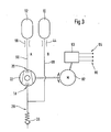
- Fig. 1 shows a first embodiment of a pneumatic circuit, as it may be integrated, for example in a vehicle seat to achieve a massage effect.
- a system consists of at least two receivers 10 and 12, which may be formed for example in the form of inflatable air cushion.
- the two recipients 10 and 12 are connected to connecting means in the form of hoses 14 and 16 with the suction side 18 and the pressure side 20 of a feed pump 22.
- the pump 22 is driven by an electric motor 24, which is controlled by a not further shown control unit.
- the delivery rate of the pump 22 can be controlled by a controllable valve 30, which is arranged in a bypass 32 between the suction side 18 and the pressure side 20 of the feed pump 22.
- the controllable valve 30 may have, for example, a controller which is connected to the central control unit of the pneumatic circuit, which also controls the electric motor 24 of the feed pump 22.
- a control valve 34 may be arranged on the pressure side of the feed pump. By means of a corresponding control, the pressure in the cushions and the frequency of the admission of the cushions to the working fluid can be influenced.
- the alternating admission of the air cushion with a pressure medium flow is realized by an actuator 36, which makes it possible, depending on the position of the actuator, to connect the pressure side 20 of the feed pump 22 either to the recipient 12 or alternatively to the recipient 10.
- the remaining second recipient is then respectively connected to the suction side 18 of the feed pump 22.
- the shows Fig. 1 a position of the actuator 36, which connects the recipient 10 with the pressure side 20 and the recipient 12 with the suction side 18 of the feed pump 22.
- the feed pump 22 is therefore in the embodiment of the Fig. 1 the recipient 10 is supplied with the pressure medium flow of the working fluid while at the same time the working fluid from the recipient 12 is actively pumped out by the feed pump 22.
- the connecting means or in the feed pump pressure sensors may be located, which monitor the pressure in the container to be filled.
- the control unit for example, the feed pump 22 a certain delivery time specify that determines the final pressure in the recipient to be filled at a known capacity of this pump. In addition, this final pressure can be adjusted for example via the control valves 30 and 34, respectively. If the actuator 36 changes its position, the filled recipient 10 is now connected to the suction side of the feed pump 22, so that this recipient is now actively emptied and the working fluid is pumped through the feed pump 22 into the recpient 12 to be filled.
- the frequency of change for the position of the actuator 36 By specifying the frequency of change for the position of the actuator 36 so, for example, the frequency of the alternating admission of the two recipients with the working fluid can be specified.
- the actuator 36 may be operated, for example mechanically or pneumatically.
- Fig. 1 shown pneumatic system can be integrated in an advantageous manner in the vehicle seat of a motor vehicle, this system is not limited to the use of only two recipients. Rather, should with the embodiment according to Fig. 1 the basic sequence of the method according to the invention and the basic structure of the associated pneumatic circuit according to the invention are explained.
- a real pneumatic system for producing a massage effect in a vehicle seat may have a plurality of airbags to be acted upon.
- the feed pump or the motor driving the pump need not be mounted in the immediate vicinity of the recipient, but may be housed to avoid excessive noise via appropriate connection means at some distance to the recipient and thus to the vehicle occupants.
- Fig. 2 shows an embodiment of a pneumatic circuit according to the invention, in which the actuator 36 is a pneumatic actuator.
- pneumatic circuit shows an actuator 36 which connects the pressure side 20 of the feed pump 22 with a first output channel 38 and at the same time a second output channel 40 with the suction side 18 of the feed pump 22.
- Upstream of the actuator 36 on the pressure side of the feed pump 20 is a control valve 34.
- the output channel 38 of the actuator 36 is connected via connecting means 42 to the recipient 10.
- the connecting means 42 has inter alia a throttle 44, with which the flow through the connecting means 42 can be adjusted in the desired manner.
- a further connecting means 46 which leads via a delay element 48, which is realized in the present embodiment by a throttle 50, to a reservoir 52 which can be emptied via a check valve 54 and the connecting means 46.
- the reservoir 52 is in turn coupled to the actuator 36 via a device 56.
- the second output channel 40 of the actuator 36 is connected on the one hand via connecting means 58 and a throttle 60 to the second recipient 12 and on the other hand via connecting means 62 and a throttle 64 to a second reservoir 66 coupled.
- the supply line to the reservoir 66 also has a delay element 68 and a check valve 70 for the venting of the reservoir.
- the reservoir 66 is, like the reservoir 52, connected via a device 72 to the actuator 36, but this on the opposite side.
- the actuator 36 has in its interior through channels, the respective connection between the pressure side 20 with one of the connecting means 42 and 58, and a connection of the suction side 18 of the feed pump 22 with the respective, not connected to the pressure side connecting means 42 and 58 produces.
- the mobility of the actuator 36 is controlled by a counter device 76, which in the Fig. 2 is shown schematically as an elastic spring, regulated.
- the operation of the pneumatic circuit according to the invention according to the embodiment of the Fig. 2 be described in more detail.
- a working fluid such as air
- the pressure medium passes through a channel 78 and the throttle 44 into the recipient 10, which may be formed, for example, as an elastic air cushion.
- the air cushion 10 will fill with the pressure medium and be inflated accordingly.
- the recipient 12 is at this time connected via a channel 80 with the suction side of the feed pump 22, so that the working fluid present in the recipient 12 via the connecting lines and the feed pump 22 to the recipient 10 is supplied.
- the working space 52 is, for example, via an elastic membrane or another Device 56 connected to the actuator 36. Now, when the pressure in the working space 52 increases, and the membrane or the corresponding device 56 expands, a force is exerted on the actuator 36.
- the actuator 36 is connected via a counter device 76, which in Fig. 2 in the form of two elastic springs is indicated, locked. If the force exerted on the actuator 36 by the pressure in the working chamber 52 exceeds the latching force of the actuator 36, this is displaced and assumes the alternatively possible position.
- a part of the working fluid conveyed by the feed pump is supplied to the working space 66 via the connection means 62 and the delay throttle 64.
- the pressure in the second working space 66 now increases according to the setting of the throttle 64, while the recipient 12, which in the case described may be another inflatable air cushion, is inflated.
- a corresponding device 86 for example a membrane
- the rising pressure in the working space 66 is transmitted to the pneumatic actuator 36, so that a force against the spring force of the counter spring 76 results therefrom. If this force is sufficiently large to overcome the latching force of the actuator 36 due to the counter device 76, ie, a sufficiently high pressure has built up in the working space 66, the actuator is again in its first, in Fig. 2 shown pushed back position, so that the second recipient 12 is now again, connected to the suction side of the feed pump 22, actively emptied.
- the comfort and achieve relief of the spine by adjusting itself massage effect can be improved with a system based on this invention in the seat of a motor vehicle, the comfort and achieve relief of the spine by adjusting itself massage effect.
- the frequency of this movement can be adjusted via the setting of the relative throttle sizes 64 and 48, the size of the volumes involved and not least also via the conveyed pressure medium flow.
- By directly adjusting the strength of the counter device 76 it is also easily possible for the user himself, for example, to customize the frequency of the movement individually.
- a small compressor such as a vane pump or a diaphragm pump can be used.
- Fig. 3 shows an alternative embodiment of a pneumatic system according to the invention, which makes it possible in a simple manner to realize an alternating admission to at least two recipients of a pneumatic system with a pressure medium flow.
- a first recipient 10 is connected via a throttle 44 and connecting means 88 with the suction side 18 of a feed pump 22.
- the pressure side 20 of the pump 22 is in turn connected via connecting means 90 and a throttle 58 to a second recipient 12.
- the pneumatic system according to the invention thus constitutes a closed circuit.
- the output valve 26 is, in the manner already described, possible air or other working fluid of outside into the system.
- the valve 26, which may be configured for example as a check valve, are opened.
- Fig. 3 is the reciprocal filling of the two recipients in a simple manner by reversing the direction of rotation of the feed pump 22, which may for example be designed in the form of a vane pump, possible.
- the motor 92 driving the delivery pump 22 can be regulated.
- the frequency of the alternating Druckstoffschbeetz Anlagenng be varied.
- the pump control unit 93 which may be part of a higher-level control unit, for example, information to various sensors 95, for example, sensors for weight, height or environmental parameters such as the vehicle interior temperature can be supplied.
- various sensors 95 for example, sensors for weight, height or environmental parameters such as the vehicle interior temperature
- stored in the control unit of the electric motor 92 curves a user and driving situation specific control of the pneumatic system can be realized. For example, the effect can be taken into account that, in the case of a strong irritation of the vehicle interior, the pressure in the recipient can rise due to a thermal expansion of the working fluid.
- various massage programs can be stored on the characteristic curves in the control unit and be retrieved, for example, by a corresponding control element by the vehicle user or the vehicle occupants.
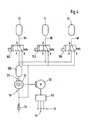
- Fig. 4 shows a further embodiment of a pneumatic circuit according to the invention, in which more than the at least two recipients are used.
- the illustrated three recipients are representative of any number of recipients that may include such a pneumatic system and are not intended to be limiting of the generality of the pneumatic circuit according to the invention.
- Fig. 4 In the embodiment of Fig. 4 three recipients 10, 11 and 12 are connected via respective connecting means 94, 96 and 98, each with an actuator 100, 102 and 104, respectively.
- the actuators for example, the pneumatic actuators according to the embodiment in Fig. 2 can connect in their, in Fig. 4 illustrated position the recipient 10, 11 and 12 with the suction side 18 of a feed pump 22. In this case, the actuators in Fig. 4 placed such that all three containers 10, 11, 12 are emptied simultaneously by the feed pump 22.
- An alternative circuit of the actuators is of course also possible in which, for example, a certain number of recipients is actively emptied, while a different number of existing recipients is acted upon simultaneously by the feed pump with the working fluid.
- the actuators of the pneumatic circuit according to the invention of those in Fig. 4 can be switched by respective switching programs synchronously or asynchronously to each other. In this way it is possible to have different massage programs with a constant Number of recipients in the pneumatic system to realize.
- the recipients 10, 11 and 12 are connected by the change of the actuators in its second possible position with the pressure side 20 of the feed pump, so that the working fluid in the second position of the actuators 10, 11 and 12 is pumped into the Rezpienten.
- the pressure side of the feed pump may also have, for example, a supply recipient 106, which is filled with the working fluid by the feed pump and can pass on the working fluid via a corresponding valve element to the recipient connected to the pressure side of the feed pump.
- the inventive method for alternately pressurizing a pneumatic system with a pressure medium flow or the corresponding pneumatic circuit for performing this method are not limited to the embodiments illustrated in the figures.
- the method and the associated device are not limited to the use of air as a working medium.
- air is preferred as the readily available and therefore inexpensive working fluid, other gaseous working fluids are also possible.
- the use of water or other liquid working fluids has the problem that a leak in the system can lead to moisture penetration of the vehicle seat, so that it can be foreseen from the use of liquid working fluids.
- the inventive method and the corresponding pneumatic circuit are not limited to the application in a massage system and in particular not limited to the use in the vehicle seats of a motor vehicle. Rather, such a pneumatic system can be used in a variety of technical applications.
Description
Die Erfindung bezieht sich auf ein Verfahren zur alternierenden Beaufschlagung mindestens zweier Rezipienten eines pneumatischen Systems, beispielsweise eines Massage-Systems eines Kraftfahrzeugsitzes mit einem Druckmittelstrom. Ferner bezieht sich die Erfindung auf eine pneumatische Schaltung zur Durchführung dieses Verfahrens.The invention relates to a method for alternately pressurizing at least two recipients of a pneumatic system, for example a massage system of a motor vehicle seat with a pressure medium flow. Furthermore, the invention relates to a pneumatic circuit for carrying out this method.
Pneumatische Steuer- und Regelschaltungen werden in einer Vielzahl von technischen Anwendungen benutzt. So werden im Kraftfahrzeugbereich beispielsweise pneumatische Verfahren und entsprechende pneumatische Schaltungen benutzt, um beispielsweise die ansonsten standardisierte Kontur der Fahrzeugsitze äußeren Einflüssen bzw. den individuellen Wünschen des Kraftfahrzeugnutzers anzupassen.Pneumatic control and regulation circuits are used in a variety of technical applications. For example, in the automotive sector, pneumatic methods and corresponding pneumatic circuits are used, for example, to adapt the otherwise standardized contour of the vehicle seats to external influences or to the individual wishes of the motor vehicle user.
Aus der
Die kombinierte, pneumatische und elektrische Schaltung dieser Vorrichtung gestattet es durch die Vielzahl der Ventile, definierte Drücke in den einzelnen Luftkammern des Sitzes aufzubauen und so, sowohl den Komfort des Sitzes zu erhöhen, als auch longitudinalen oder lateralen Beschleunigungen des Fahrzeuges Rechnung zu tragen.The combined, pneumatic and electrical circuit of this device allows the plurality of valves to build defined pressures in the individual air chambers of the seat and so, both to increase the comfort of the seat, and to take into account longitudinal or lateral accelerations of the vehicle.
Im Besonderen gestattet es die Vorrichtung der
Zur Erzielung dieser Variation in den Druckverhältnissen der einzelnen Luftkammern des Sitzes der
Die
Aufgabe der vorliegenden Erfindung ist es, ein Verfahren bzw. eine pneumatische Schaltung zur alternierenden Beaufschlagung mindestens zweier Rezipienten eines pneumatischen Systems mit einem Druckmittelstrom zu realisieren, welches auf einfache aber zuverlässige Weise die hinreichende Befüllung der beteiligten Rezipienten ermöglicht.Object of the present invention is to realize a method or a pneumatic circuit for alternately pressurizing at least two recipients of a pneumatic system with a pressure medium flow, which allows a simple but reliable way, the adequate filling of the recipients involved.
Die Aufgabe wird gelöst durch das erfindungsgemäße Verfahren bzw. durch die erfindungsgemäße pneumatische Schaltung mit den Merkmalen des Anspruchs 1 bzw. des Anspruchs 10.The object is achieved by the method according to the invention or by the pneumatic circuit according to the invention with the features of claim 1 or of
Das erfindungsgemäße Verfahren zur alternierenden Beaufschlagung mindestens zweier Rezipienten eines pneumatischen Systems, insbesondere eines pneumatischen Massage-Systems für einen Kraftfahrzeugsitz, mit einem Druckmittelstrom bzw. die entsprechende pneumatische Schaltung sieht vor, dass zumindest ein als Rezipient dienendes erstes Luftkissen mit einem gasförmigen Arbeitsfluid gefüllt wird, während das Arbeitsfluid aus mindestens einem weiteren, zweiten Luftkissen aktiv abgesaugt wird. Das erfindungsgemäße Verfahren bzw. die pneumatische Schaltung zur Durchführung dieses Verfahrens verbessert die Wirkungsweise beispielsweise eines luftkammergetriebenen Massagesystems in einem Fahrzeugsitz, in dem die passive Entlüftung der Kissen gemäß dem Stand der Technik durch eine aktive Entlüftung ersetzt wird. Eine passive Entlüftung hängt stark von den Umgebungsbedingungen (beispielsweise Sitzaufbau, Fahrergewicht, Umgebungstemperatur, ...) ab. Bei einer aktiven Evakuierung der beteiligten Kissen wird der erzielbare Massageeffekt stärker spürbar. In einem Sitzmassagesystem, das aus mindestens zwei Luftkissen besteht, die in einem Fahrzeugsitz eingebaut sind, wird abwechselnd ein Kissen mit Luft bzw. einem anders gearteten, gasförmigen Arbeitsfluid gefüllt und in dem anderen Kissen wird die Luft aktiv abgesaugt. Durch diese Absaugung der Luft wird das entsprechende Kissen besser entleert und somit die Massagewirkung, die abhängig ist von der Druckdifferenz in den beteiligten Luftkissen, verstärkt.The inventive method for alternately pressurizing at least two receivers of a pneumatic system, in particular a pneumatic massage system for a motor vehicle seat, with a pressure medium flow or the corresponding pneumatic circuit provides that at least serving as a recipient first air cushion is filled with a gaseous working fluid, while the working fluid is actively removed from at least one further, second air cushion. The method according to the invention or the pneumatic circuit for carrying out this method improves the operation of, for example, a ventilation chamber-driven massage system in a vehicle seat, in which the passive ventilation of the cushions according to the prior art is replaced by an active ventilation. Passive venting is highly dependent on environmental conditions (eg seat design, rider weight, ambient temperature, ...). With an active evacuation of the pillows involved, the achievable massage effect becomes more noticeable. In a seat massage system, which consists of at least two air cushions, which are installed in a vehicle seat, a cushion is alternately filled with air or other type, gaseous working fluid and in the other cushion, the air is actively sucked. Through this extraction of air, the corresponding pillow is better emptied and thus the massage effect, which is dependent on the pressure difference in the air cushion involved, reinforced.
Durch die in den weiteren Ansprüchen aufgeführten Maßnahmen und Merkmale sind vorteilhafte Verbesserungen und Weiterbildungen des in Anspruch 1 angegebenen Verfahrens, bzw. der in Anspruch 10 beschriebenen pneumatischen Schaltung möglich.The measures and features listed in the further claims, advantageous improvements and developments of the method specified in claim 1, or the pneumatic circuit described in
In vorteilhafter Weise kann der Druck in dem mindestens einen, zu leerenden Luftkissen zur Befüllung des mindestens einen zu befüllenden Luftkissens verwendet werden. Dabei sei die Bezeichnung "Luftkissen" nicht beschränkt auf die Verwendung von Luft als Arbeitsfluid des pneumatischen Systems. Auch der Begriff "Kissen" ist in einem weiteren Sinne zu verstehen und soll zumindest einen aufpumpbaren Rezipienten umfassen. Ein solches pneumatisches System lässt mit einer ganzen Reihe von gasförmigen Arbeitsfluiden realisieren. Durch die aktive Entleerung des einen Luftkissens kann der Druck in dem zu entleerenden Kissen zur Befüllung eines anderen Kissens genutzt werden, anstatt wie in den entsprechenden Systemen des Standes der Technik in die Umgebung zu entweichen. Dieser im Wesentlichen geschlossene Arbeitskreis bedeutet eine Verbesserung des Wirkungsgrades des pneumatischen Systems sowie eine Energieersparnis beim Betrieb eines solchen Systems.Advantageously, the pressure in the at least one air cushion to be emptied can be used to fill the at least one air cushion to be filled. The term "air cushion" is not limited to the use of air as the working fluid of the pneumatic system. The term "pillow" is to be understood in a broader sense and is intended to include at least one inflatable recipient. Such a pneumatic system can be realized with a whole series of gaseous working fluids. By actively draining the one air bag, the pressure in the pad to be dumped can be used to fill another pad rather than escape into the environment as in the corresponding prior art systems. This essentially closed working group means an improvement in the efficiency of the pneumatic system and an energy saving in the operation of such a system.
In einer vorteilhaften Ausführungsform des erfindungsgemäßen Verfahrens wird die wechselseitige Befüllung der Luftkissen durch eine Drehrichtungsumkehr der das Arbeitsfluid fördernden Pumpe erreicht. Die Verwendung einer solchen Pumpe gestattet es, auf sehr einfache Weise, die beteiligten Luftkissen alternierend zu befüllen bzw. zu entleeren. Eine solche Pumpe wird in vorteilhafter Weise von einem Elektromotor getrieben, dessen Drehzahl und Drehrichtung beispielsweise über ein entsprechendes Steuergerät vorgebbar ist.In an advantageous embodiment of the method according to the invention, the mutual filling of the air cushion is achieved by reversing the direction of rotation of the pumping the working fluid. The use of such a pump makes it possible, in a very simple way, to fill or empty the airbags involved alternately. Such a pump is driven in an advantageous manner by an electric motor whose speed and direction of rotation can be predetermined, for example via a corresponding control unit.
Auf diese Weise lässt sich ein pneumatisches System realisieren, bei dem der Enddruck in dem zu füllenden Rezipienten (Luftkissen), bzw. die Frequenz der alternierenden Beaufschlagung der beteiligten Rezipienten mit einem Druckmittelstrom, vorgebbar ist.In this way, a pneumatic system can be realized, in which the final pressure in the recipient to be filled (air cushion), or the frequency of the alternating admission of the recipients involved with a pressure medium flow, can be predetermined.
So kann beispielsweise der Enddruck in den zu füllenden Kissen, der die Härte des Fahrzeugsitzes bestimmt und die Stärke des Massageeffekts festlegt beispielsweise über entsprechende Bedienelemente manuell vorgegeben werden. Auf diese Weise ist es möglich, unterschiedlichen Nutzern bzw. unterschiedlichen Nutzbedingungen des Fahrzeuges bzw. des Fahrzeugsitzes Rechnung zu tragen. Neben dem gewünschten Enddruck in den Luftkissen kann beispielsweise auch die Frequenz mit der die Luftkissen befüllt und entleert werden, manuell eingestellt und somit der individuellen Fahrsituation angepasst werden.Thus, for example, the final pressure in the pillow to be filled, which determines the hardness of the vehicle seat and determines the strength of the massage effect, for example, be manually specified via corresponding controls. In this way it is possible to accommodate different users or different conditions of use of the vehicle or the vehicle seat. In addition to the desired End pressure in the air cushion, for example, the frequency with which the air bags are filled and emptied manually adjusted and thus adapted to the individual driving situation.
In einem alternativen Ausführungsbeispiel des erfindungsgemäßen Verfahrens wird die Befüllung der Rezipienten durch ein Steuergerät geregelt, welches über diverse Detektoren Informationen über die Sitzbelegung erhält. So kann beispielsweise das Gewicht eines Fahrzeugnutzers, die Körpergröße oder aber auch die bereits verstrichene Fahrzeit über entsprechende Sensoren detektiert werden und an das Steuergerät übermittelt werden. Im Steuergerät können über entsprechend abgelegte Kennlinien dem Fahrertyp und der Fahrsituation angepasste Steuerprogramme zur Aktivierung der Luftkissen ausgewählt werden. So ist es beispielsweise möglich, einer sehr langen Fahrzeit Rechnung zu tragen, indem ein leichter Massageeffekt der Ermüdung des Fahrers entgegenwirkt. Auch ist es denkbar, den sogenannten Sekundenschlaf eines Fahrers zu detektieren und den Fahrer durch einen verstärkten Massageeffekt auf diese Situation aufmerksam zu machen und vor weiterem "Wegnicken" zu bewahren.In an alternative embodiment of the method according to the invention, the filling of the recipient is controlled by a control unit, which receives information about the seat occupancy via various detectors. Thus, for example, the weight of a vehicle user, the body size or even the already elapsed travel time can be detected via corresponding sensors and transmitted to the control unit. In the control unit, control programs for activating the airbags adapted to the driver type and the driving situation can be selected via correspondingly stored characteristic curves. So it is possible, for example, to take into account a very long journey time by a slight massage effect counteracts the fatigue of the driver. It is also conceivable to detect the so-called microsleep of a driver and to make the driver aware of this situation by means of an intensified massage effect and to prevent further "nodding".
In einer Ausführungsform des erfindungsgemäßen Verfahrens wird der Enddruck in dem mindestens einen zu füllenden Rezipienten und/oder die Frequenz der alternierenden Beaufschlagung der mindestens zwei Rezipienten mit dem Arbeitsfluid durch eine Drosselung des Druckmittelstromes auf der Druckseite der Förderpumpe, insbesondere durch ein Drosselventil, gesteuert bzw. geregelt.In one embodiment of the method according to the invention, the final pressure in the at least one recipient to be filled and / or the frequency of the alternating application of the at least two recipients with the working fluid by a throttling of the pressure medium flow on the pressure side of the feed pump, in particular by a throttle valve controlled or regulated.
In einer alternativen Ausführungsform wird der Enddruck bzw. die Frequenz der Beaufschlagung durch Betätigung eines Bypasses zwischen der Saug- und Druckseite der Förderpumpe für das Arbeitsfluid gesteuert bzw. geregelt.In an alternative embodiment, the end pressure or the frequency of the application is controlled or controlled by actuation of a bypass between the suction and pressure side of the pump for the working fluid.
In vorteilhafter Weise weist die pneumatische Schaltung zur alternierenden Beaufschlagung mindestens zweier Rezipienten eines pneumatischen Systems mit einem Druckmittelstrom eine Förderpumpe und Verbindungsmittel auf, die derart miteinander verbunden sind, dass der mindestens eine, erste Rezipient über die Verbindungsmittel und die Förderpumpe mit dem mindestens einen, zweiten Rezipienten verbunden ist. Auf diese Weise ergibt sich ein im Wesentlichen geschlossenes Fördersystem in dem das Arbeitsmedium lediglich umgepumpt wird. Darüber hinaus kann die pneumatische Schaltung auch einen Rezipienten aufweisen, der als Vorratsbehältnis für das Arbeitsfluid dient.Advantageously, the pneumatic circuit for alternately pressurizing at least two receivers of a pneumatic system with a pressure medium flow to a feed pump and connecting means which are interconnected such that the at least one, first recipient via the connecting means and the feed pump with the at least one, second Recipients is connected. In this way, a substantially closed conveyor system results in which the working medium is merely pumped around. In addition, the pneumatic Circuit also have a recipient, which serves as a storage container for the working fluid.
Es kann beispielsweise die Ansaugseite der Förderpumpe mit einem ersten Rezipienten verbunden sein, während gleichzeitig die Druckseite der Förderpumpe mit einem zweiten Rezipienten verbunden ist. Durch Drehrichtungsumkehr der Förderpumpe lässt sich auf diese Weise ein einfaches Umpumpen des Arbeitsfluids realisieren.For example, the suction side of the feed pump may be connected to a first recipient, while at the same time the pressure side of the feed pump is connected to a second recipient. By reversing the direction of rotation of the pump can be realized in this way a simple pumping of the working fluid.
In einem weiteren Ausführungsbeispiel der erfindungsgemäßen pneumatischen Schaltung kann auf der Ansaugseite der Förderpumpe ein den Druckmittelsrom steuerndes Bauelement mit mindestens einem Rezipienten verbunden sein. Eine entsprechende Ausgestaltung des steuernden Bauelementes ermöglicht es, dass zudem auch die Druckseite der Förderpumpe gleichzeitig mit demselben Bauelement verbunden ist.In a further exemplary embodiment of the pneumatic circuit according to the invention, a component controlling the pressure medium flow can be connected to at least one recipient on the suction side of the feed pump. A corresponding embodiment of the controlling component makes it possible that, in addition, the pressure side of the feed pump is simultaneously connected to the same component.
In vorteilhafter Weise lässt sich ein solches Drucksteuermittel als ein pneumatisch getriebenes Stellglied realisieren, welches die alternierende Beaufschlagung der Rezipienten regelt. In diesem Falle ist die Verwendung einer einfachen Förderpumpe, ohne die Möglichkeit der Drehrichtungsumkehr möglich.Advantageously, such a pressure control means can be realized as a pneumatically driven actuator, which regulates the alternating admission of the recipient. In this case, the use of a simple feed pump, without the possibility of reversing the direction of rotation is possible.
Als Drucksteuermittel kann in einfacher und daher vorteilhafter Weise auch ein Bauelement mit einem regelbaren bzw. schaltbaren Ventil genutzt werden.As a pressure control means can be used in a simple and therefore advantageous manner, a component with a controllable or switchable valve.
In vorteilhafter Weise kann die Förderpumpe als Flügelzellenpumpe, insbesondere als Flügelzellenpumpe mit Mitteln zur Drehrichtungsumkehr ausgestaltet sein. In einem weiteren vorteilhaften Ausführungsbeispiel der pneumatischen Schaltung weisen die Verbindungsmittel zwischen der Förderpumpe und den Rezipienten ein Ausgangsventil auf, welches bei Erreichen einer bestimmten Druckgrenze auf der Saugseite der Förderpumpe, die Verbindungsleitung öffnet, um zusätzliches Arbeitsfluid dem System zuzuführen.Advantageously, the feed pump can be designed as a vane pump, in particular as a vane pump with means for reversing the direction of rotation. In a further advantageous embodiment of the pneumatic circuit, the connecting means between the feed pump and the recipient on an output valve which opens upon reaching a certain pressure limit on the suction side of the feed pump, the connecting line to supply additional working fluid to the system.
In vorteilhafter Weise lässt sich solch ein pneumatisches System in einen Fahrzeugsitz, insbesondere in den Sitz eines Kraftfahrzeugs einbauen, so dass in dem Fahrzeugsitz mit Hilfe des erfindungsgemäßen Verfahrens ein Massageeffekt realisierbar ist, der den Fahrzeugkomfort vergrößert sowie die Fahrsicherheit erhöht.Advantageously, such a pneumatic system can be installed in a vehicle seat, in particular in the seat of a motor vehicle, so that in the vehicle seat by means of the method according to the invention a massage effect can be realized, which increases vehicle comfort and increases driving safety.
Mit dem erfindungsgemäßen Verfahren bzw. der erfindungsgemäßen pneumatischen Schaltung zur Durchführung dieses Verfahrens ist es möglich, die Wirkungsweise eines Massagesystems, insbesondere eines Massagesystems für einen Fahrzeugsitz zu verbessern, indem die passive Entlüftung der Rezipienten durch eine aktive Entlüftung ersetzt wird. So ist es insbesondere möglich ein Massagesystem zu realisieren, das weitgehend unabhängig ist von den Umgebungsbedingungen.With the method according to the invention or the pneumatic circuit according to the invention for carrying out this method, it is possible to improve the operation of a massage system, in particular a massage system for a vehicle seat by replacing the passive venting of the recipient by an active vent. So it is possible in particular to realize a massage system that is largely independent of the ambient conditions.
In der Zeichnung sind Ausführungsbeispiele der erfindungsgemäßen, pneumatischen Schaltung dargestellt, die in der nachfolgenden Beschreibung näher erläutert werden sollen. Die Figuren der Zeichnung, deren Beschreibung sowie die Ansprüche enthalten zahlreiche Merkmale in Kombination. Ein Fachmann wird diese Merkmale auch einzeln betrachten bzw. zu weiteren, sinnvollen Kombinationen zusammenfassen.In the drawings, embodiments of the pneumatic circuit according to the invention are shown, which will be explained in more detail in the following description. The figures of the drawing, the description and the claims contain numerous features in combination. A person skilled in the art will also consider these features individually or combine them into further, meaningful combinations.
Es zeigen:
- Fig. 1
- ein erstes Ausführungsbeispiel einer pneumatischen Schaltung zur Durchführung des erfindungsgemäßen Verfahrens,
- Fig. 2
- ein zweites Ausführungsbeispiel einer erfindungsgemäßen pneumatischen Schaltung,
- Fig. 3
- ein weiteres Ausführungsbeispiel einer erfindungsgemäßen pneumatischen Schaltung,
- Fig. 4
- ein weiteres Ausführungsbeispiel einer erfindungsgemäßen pneumatischen Schaltung mit einer vergrößerten Anzahl von Rezipienten.
- Fig. 1
- A first embodiment of a pneumatic circuit for carrying out the method according to the invention,
- Fig. 2
- A second embodiment of a pneumatic circuit according to the invention,
- Fig. 3
- a further embodiment of a pneumatic circuit according to the invention,
- Fig. 4
- a further embodiment of a pneumatic circuit according to the invention with an increased number of recipients.
Die Förderleistung der Pumpe 22 kann durch ein regelbares Ventil 30, welches in einem Bypass 32 zwischen der Saugseite 18 und der Druckseite 20 der Förderpumpe 22 angeordnet ist, geregelt werden. Dazu kann das regelbare Ventil 30 beispielsweise eine Steuerung besitzen, die mit dem zentralen Steuergerät der pneumatischen Schaltung, welches auch den Elektromotor 24 der Förderpumpe 22 regelt, verbunden ist.The delivery rate of the
Alternativ oder zusätzlich kann ein Regelventil 34 auf der Druckseite der Förderpumpe angeordnet sein. Durch eine entsprechende Regelung kann der Druck in den Kissen und die Frequenz der Beaufschlagung der Kissen mit dem Arbeitsfluid beeinflusst werden.Alternatively or additionally, a
In dem vorliegenden Ausführungsbeispiel der
In den Rezipienten, den Verbindungsmitteln bzw. auch in der Förderpumpe können sich Drucksensoren befinden, die den Druck im zu befüllenden Rezipienten überwachen. Auch kann das Steuergerät beispielsweise der Förderpumpe 22 eine bestimmte Förderzeit vorgeben, die bei bekannter Förderleistung dieser Pumpe den Enddruck in dem zu befüllenden Rezipienten bestimmt. Darüber hinaus kann dieser Enddruck beispielsweise auch über die Regelventile 30 bzw. 34 eingeregelt werden. Wechselt das Stellglied 36 seine Position, so wird der befüllte Rezipient 10 nun mit der Saugseite der Förderpumpe 22 verbunden, so dass dieser Rezipient nun aktiv entleert wird und das Arbeitsfluid durch die Förderpumpe 22 in den nun zu befüllenden Rezpienten 12 umgepumpt wird.In the recipient, the connecting means or in the feed pump pressure sensors may be located, which monitor the pressure in the container to be filled. Also, the control unit, for example, the feed pump 22 a certain delivery time specify that determines the final pressure in the recipient to be filled at a known capacity of this pump. In addition, this final pressure can be adjusted for example via the
Durch die Vorgabe der Wechselfrequenz für die Stellung des Stellgliedes 36 kann so beispielsweise die Frequenz der alternierenden Beaufschlagung der zwei Rezipienten mit dem Arbeitsfluid vorgegeben werden. Das Stellglied 36 kann beispielsweise mechanisch oder aber auch pneumatisch betrieben werden.By specifying the frequency of change for the position of the
Das in
Der zweite Ausgangskanal 40 des Stellgliedes 36 ist zum Einen über Verbindungsmittel 58 und eine Drossel 60 mit dem zweiten Rezipienten 12 verbunden und andererseits über Verbindungsmittel 62 und eine Drossel 64 an ein zweites Reservoir 66 gekoppelt. Die Zuleitung zum Reservoir 66 weist ebenso ein Verzögerungsglied 68 und ein Rückschlagventil 70 für die Entlüftung des Reservoirs auf. Das Reservoir 66 ist, wie das Reservoir 52, über eine Vorrichtung 72 mit dem Stellglied 36 verbunden, dieses jedoch auf der entgegengesetzten Seite.The
Das Stellglied 36 weist in seinem Inneren durchgehende Kanäle auf, die die jeweilige Verbindung zwischen der Druckseite 20 mit einem der Verbindungsmittel 42 bzw. 58, sowie eine Verbindung der Saugseite 18 der Förderpumpe 22 mit dem jeweiligen, nicht mit der Druckseite verbundenen Verbindungsmittel 42 bzw. 58 herstellt. Die Beweglichkeit des Stellgliedes 36 wird durch eine Kontereinrichtung 76, die in der
Im Folgenden soll die Funktionsweise der erfindungsgemäßen pneumatischen Schaltung nach dem Ausführungsbeispiel der
In dieser in
Ein Teil des von der Förderpumpe beförderten Arbeitsfluids wird über die Verbindungsmittel 62 und die Verzögerungsdrossel 64 dem Arbeitsraum 66 zugeführt. Der Druck in dem zweiten Arbeitsraum 66 steigt nun gemäß der Einstellung der Drossel 64 an, während der Rezipient 12, der in dem beschriebenen Fall ein weiteres aufblasbares Luftkissen sein mag, aufgepumpt wird. Über eine entsprechende Vorrichtung 86, beispielsweise eine Membran wird der ansteigende Druck im Arbeitsraum 66 auf das pneumatische Stellglied 36 übertragen, so dass daraus eine Kraft entgegen der Federkraft der Konterfeder 76 resultiert. Ist diese Kraft hinreichend groß, um die Rastkraft des Stellgliedes 36 aufgrund der Kontereinrichtung 76 zu überwinden, hat sich also im Arbeitsraum 66 ein genügend hoher Druck aufgebaut, so wird das Stellglied wieder in seine erste, in
Damit ist ein vollständiger Zyklus des erfindungsgemäßen Verfahrens zur alternierenden Beaufschlagung mindestens zweier Rezipienten eines pneumatischen Systems mit einem Druckmittelstrom abgeschlossen und das System beginnt wieder selbstständig mit der Füllung des Rezipienten 10 wie bereits oben beschrieben.Thus, a complete cycle of the inventive method for alternately pressurizing at least two recipients of a pneumatic system is completed with a flow of pressure medium and the system starts again automatically with the filling of the
Durch das wechselseitige Befüllen bzw. Entleeren der beteiligten Luftkissen lässt sich mit einem auf dieser Erfindung basierenden System im Sitz eines Kraftfahrzeuges der Sitzkomfort verbessern und eine Entlastung der Wirbelsäule durch einen sich einstellenden Massageeffekt erreichen. Die Frequenz dieser Bewegung kann über die Einstellung der relativen Drosselgrößen 64 bzw. 48, der Größe der beteiligten Volumina und nicht zuletzt auch über den geförderten Druckmittelstrom eingestellt werden. Über die direkte Einstellung der Stärke der Kontervorrichtung 76 ist es beispielsweise auch dem Nutzer selbst leicht möglich, die Frequenz der Bewegung individuell anzupassen.By mutual filling or emptying of the airbags involved can be improved with a system based on this invention in the seat of a motor vehicle, the comfort and achieve relief of the spine by adjusting itself massage effect. The frequency of this movement can be adjusted via the setting of the relative throttle sizes 64 and 48, the size of the volumes involved and not least also via the conveyed pressure medium flow. By directly adjusting the strength of the
Zur Umwälzung des Arbeitsfluids der Vorrichtung kann ein Kleinkompressor, beispielsweise eine Flügelzellenpumpe oder auch eine Membranpumpe eingesetzt werden.For circulating the working fluid of the device, a small compressor, such as a vane pump or a diaphragm pump can be used.
Im Ausführungsbeispiel gemäß
Im Ausführungsbeispiel der
Das erfindungsgemäße Verfahren zur alternierenden Beaufschlagung eines pneumatischen Systems mit einem Druckmittelstrom bzw. die entsprechende pneumatische Schaltung zur Durchführung dieses Verfahrens sind nicht auf die in den Figuren dargestellten Ausführungsbeispiele beschränkt. Insbesondere sind das Verfahren bzw. die zugehörige Vorrichtung nicht beschränkt auf die Verwendung von Luft als Arbeitsmittel. Auch wenn Luft als leicht verfügbares und daher kostengünstiges Arbeitsmittel bevorzugt wird, sind andere gasförmige Arbeitsfluide ebenso möglich. Die Verwendung von Wasser oder anderen flüssigen Arbeitsfluiden birkt das Problem, dass ein Leck im System zu einer Durchfeuchtung des Fahrzeugsitzes führen kann, so dass von einer Verwendung von flüssigen Arbeitsfluiden abzusehen ist.The inventive method for alternately pressurizing a pneumatic system with a pressure medium flow or the corresponding pneumatic circuit for performing this method are not limited to the embodiments illustrated in the figures. In particular, the method and the associated device are not limited to the use of air as a working medium. Although air is preferred as the readily available and therefore inexpensive working fluid, other gaseous working fluids are also possible. The use of water or other liquid working fluids has the problem that a leak in the system can lead to moisture penetration of the vehicle seat, so that it can be foreseen from the use of liquid working fluids.
Das erfindungsgemäße Verfahren bzw. die entsprechende pneumatische Schaltung sind nicht beschränkt auf die Anwendung in einem Massagesystem und insbesondere nicht beschränkt auf den Einsatz in den Fahrzeugsitzen eines Kraftfahrzeuges. Vielmehr kann ein solches pneumatisches System in einer Vielzahl von technischen Anwendungen eingesetzt werden.The inventive method and the corresponding pneumatic circuit are not limited to the application in a massage system and in particular not limited to the use in the vehicle seats of a motor vehicle. Rather, such a pneumatic system can be used in a variety of technical applications.
Claims (20)
- Method for the alternating charging of at least two receptacles (10, 11, 12) of a pneumatic system, in particular a pneumatic massage system of a motor vehicle seat, with a stream of pressure medium, characterized in that at least one first air cushion (10, 11, 12) serving as a receptacle (10, 11, 12) is filled with a gaseous working fluid while the working fluid is actively sucked off from at least one further, second air cushion (10, 11, 12).
- Method according to Claim 1, characterized in that the pressure in the at least one receptacle (10, 11, 12) to be emptied is used for filling the at least one air cushion (10, 11, 12) to be filled.
- Method according to Claim 1 or 2, characterized in that the alternating filling of at least two air cushions (10, 11, 12) is achieved by reversing the direction of rotation of a pump (22) delivering the working fluid.
- Method according to Claim 3, characterized in that the rotational speed of a motor driving the feed pump (22), in particular an electric motor (24, 92), can be predetermined.
- Method according to one of the preceding claims, characterized in that the final pressure in the at least one receptacle (10, 11, 12) to be filled and/or the frequency of the alternating charging of the at least two receptacles (10, 11, 12) with the working fluid can be predetermined.
- Method according to Claim 5, characterized in that the final pressure in the at least one receptacle (10, 11, 12) to be filled and/or the frequency of the alternating charging of the at least two receptacles (10, 11, 12) with the working fluid can be predetermined manually via corresponding operating elements in the vehicle.
- Method according to Claim 5, characterized in that the final pressure in the at least one receptacle (10, 11, 12) to be filled and/or the frequency of the alternating charging of the at least two receptacles (10, 11, 12) with the working fluid is/are predetermined by a control device (93) in accordance with the signals from at least one sensor (95), in particular a sensor for detecting the seat occupancy.
- Method according to one of Claims 5, 6 or 7, characterized in that the final pressure in the at least one receptacle (10, 11, 12) to be filled and/or the frequency of the alternating charging of the at least two receptacles (10, 11, 12) with the working fluid is controlled or regulated by a throttling (34, 44, 58) of the stream of pressure medium on the delivery side (20) of the feed pump (22), in particular by means of a throttle valve (34, 44, 58).
- Method according to one of Claims 5, 6 or 7, characterized in that the final pressure in the at least one air cushion (10, 11, 12) to be filled and/or the frequency of the alternating charging of the at least two receptacles (10, 11, 12) with the working fluid is/are controlled or regulated by actuation of a bypass (32) between the intake side (18) and the delivery side (20) of the feed pump (22).
- Pneumatic circuit for the alternating charging of receptacles (10, 11, 12) of a pneumatic system, in particular a pneumatic massage system of a vehicle seat, with a stream of pressure medium, with at least two receptacles (10, 11, 12) for receiving the stream of pressure medium in an alternating manner, with at least one pump (22) delivering the stream of pressure medium, and with driving means (24) for the feed pump (22) and with connecting means (14, 16, 18, 20, 88, 90, 94, 96, 98) between the feed pump (22) and the receptacle (10, 11, 12) to be charged with a working fluid, characterized in that the at least one first receptacle (10, 11, 12) is connected to the at least one second receptacle (10, 11, 12) via the connecting means (14, 16, 18, 20, 88, 90, 94, 96, 98) and the feed pump (22).
- Pneumatic circuit according to Claim 10, characterized in that the at least two receptacles (10, 11, 12) are connected to the at least one feed pump (22) via the connecting means (14, 16, 18, 20, 88, 90, 94, 96, 98) in such a manner that the working fluid pumped out of the at least one first receptacle (10, 11, 12) can be supplied to the at least one second receptacle (10, 11, 12).
- Pneumatic circuit according to Claim 10 or 11, characterized in that the intake side (18) of the at least one feed pump (22) is connected to at least one first receptacle (10, 11, 12) while at the same time the delivery side (20) of the feed pump (22) is connected to at least one second receptacle (10, 11, 12).
- Pneumatic circuit according to one of the preceding Claims 10, 11 or 12, characterized in that the intake side (18) of the feed pump (22) is connected to at least one first receptacle (10, 11, 12) via a component (36, 100, 102, 104) which controls the stream of pressure medium, while the delivery side (20) of the pump (22) is at the same time connected to at least one second receptacle (10, 11, 12).
- Pneumatic circuit according to Claim 13, characterized in that the delivery side (20) of the feed pump (22) is also connected to the same component (36, 100, 102, 104) which controls the stream of pressure medium.
- Pneumatic circuit according to Claim 13 or 14, characterized in that the pressure control means (36, 100, 102, 104) has a pneumatically driven actuating element (36, 100, 102, 104).
- Pneumatic circuit according to Claim 15, characterized in that the pressure control means (36, 100, 102, 104) has at least one valve.
- Pneumatic circuit according to one of the preceding Claims 10 to 16, characterized in that the feed pump (22) is a vane pump, in particular a vane pump with means for reversing the direction of rotation.
- Pneumatic circuit according to one of the preceding Claims 10 to 17, characterized in that the circuit has at least one output valve (26) which, when a certain pressure limit is reached on the intake side (18) of the pump (22), opens a connecting line (28, 14, 18, 88) in order to supply additional working fluid to the system.
- Pneumatic circuit according to one of the preceding Claims 10 to 18, characterized in that the circuit has at least one sensor element (95) which obtains information about a seat occupancy and transmits said information to a control device (93) for the pneumatic circuit.
- Method for charging at least two receptacles (10, 11, 12), which are integrated in a vehicle seat, for the alternating charging with a stream of pressure medium, characterized in that the charging of the receptacles (10, 11, 12) takes place in accordance with a method according to one of Claims 1 to 9.
Applications Claiming Priority (3)
| Application Number | Priority Date | Filing Date | Title |
|---|---|---|---|
| DE10238240A DE10238240A1 (en) | 2002-08-21 | 2002-08-21 | Process for filling at least two recipients and pneumatic circuit for carrying out the process |
| DE10238240 | 2002-08-21 | ||
| PCT/DE2003/002508 WO2004020243A1 (en) | 2002-08-21 | 2003-07-25 | Method for filling at least two receptacles and pneumatic circuit for carrying out said method |
Publications (2)
| Publication Number | Publication Date |
|---|---|
| EP1532016A1 EP1532016A1 (en) | 2005-05-25 |
| EP1532016B1 true EP1532016B1 (en) | 2008-05-28 |
Family
ID=31197172
Family Applications (1)
| Application Number | Title | Priority Date | Filing Date |
|---|---|---|---|
| EP03790652A Expired - Lifetime EP1532016B1 (en) | 2002-08-21 | 2003-07-25 | Method for filling at least two receptacles and pneumatic circuit for carrying out said method |
Country Status (5)
| Country | Link |
|---|---|
| US (1) | US20050242644A1 (en) |
| EP (1) | EP1532016B1 (en) |
| JP (1) | JP2005536297A (en) |
| DE (2) | DE10238240A1 (en) |
| WO (1) | WO2004020243A1 (en) |
Families Citing this family (11)
| Publication number | Priority date | Publication date | Assignee | Title |
|---|---|---|---|---|
| DE102004045573B4 (en) * | 2004-09-17 | 2007-11-15 | Grammer Ag | Seat with an ergo-mechanic |
| US8449483B2 (en) * | 2008-12-02 | 2013-05-28 | Patrick Eddy | Compression device and control system for applying pressure to a limb of a living being |
| EP2361800B1 (en) * | 2010-02-17 | 2013-04-24 | L & P Swiss Holding AG | Adjusting device for a seat and method of operating an adjusting device |
| EP2461046B1 (en) * | 2010-12-03 | 2017-11-01 | Schukra Gerätebau GmbH | Valve assembly and pneumatic seat adjusting device |
| DE102010054492A1 (en) | 2010-12-14 | 2012-06-21 | Faurecia Autositze Gmbh | Massage device for use in backrest of vehicle seat to e.g. avoid distortions of back of user, has airbag device formed with inflatable chambers and filled with air through single air line, where chambers are connected to channels |
| US9211824B2 (en) * | 2012-04-30 | 2015-12-15 | Ford Global Technologies, Llc | Adjustable firmness vehicle seat |
| DE102012025306A1 (en) * | 2012-12-22 | 2014-06-26 | Daimler Ag | Seat system for a motor vehicle |
| DE102014211486B4 (en) * | 2014-06-16 | 2021-08-19 | Conti Temic Microelectronic Gmbh | Pneumatic adjustment arrangement for a vehicle seat and vehicle seat |
| DE202015009848U1 (en) | 2015-04-09 | 2020-09-21 | Alfmeier Präzision SE | Device for setting a contour of a vehicle seat with contour adjustment |
| DE102016204845A1 (en) * | 2016-03-23 | 2017-09-28 | Brose Fahrzeugteile Gmbh & Co. Kommanditgesellschaft, Coburg | Method for controlling a motor of a provided in a seat massage unit, control device and seat assembly |
| JP6856879B2 (en) * | 2019-07-29 | 2021-04-14 | テイ・エス テック株式会社 | Vehicle seat |
Family Cites Families (15)
| Publication number | Priority date | Publication date | Assignee | Title |
|---|---|---|---|---|
| US2780222A (en) * | 1953-12-18 | 1957-02-05 | J J Monaghan Company Inc | Respirators |
| US4175297A (en) * | 1978-02-03 | 1979-11-27 | Richardson Robert H | Inflatable pillow support |
| JPS57126224A (en) * | 1981-01-27 | 1982-08-05 | Mitsubishi Electric Corp | Input circuit for protection relay unit |
| GB2144984A (en) * | 1983-08-13 | 1985-03-20 | Ian Leslie Cameron | Seat with variable support |
| US4989589A (en) * | 1983-11-07 | 1991-02-05 | Pekanmaeki Kalle | Device for massaging extermities, such as legs |
| US4655505A (en) * | 1984-12-13 | 1987-04-07 | Nhk Spring Co., Ltd. | Pneumatically controlled seat for vehicle |
| GB8526785D0 (en) * | 1985-10-30 | 1985-12-04 | Pirelli Ltd | Inflation pump |
| US4986260A (en) * | 1986-06-06 | 1991-01-22 | Superspine, Inc. | Apparatus and method for providing continuous passive motion to the spine |
| GB8804864D0 (en) * | 1988-03-01 | 1988-03-30 | Pirelli Ltd | System for inflating support bag in seat |
| JP2751431B2 (en) * | 1989-07-14 | 1998-05-18 | 日産自動車株式会社 | Sheet |
| US5135282A (en) * | 1989-08-18 | 1992-08-04 | Man Nutzfahrzeuge Aktiengesellschaft | Motor vehicle seat back |
| US5029939A (en) * | 1989-10-05 | 1991-07-09 | General Motors Corporation | Alternating pressure pad car seat |
| IT1285059B1 (en) * | 1996-04-26 | 1998-06-03 | Magneti Marelli Spa | ROTARY VANE DEPRESSOR. |
| DE19726410B4 (en) * | 1997-06-21 | 2008-04-30 | Bayerische Motoren Werke Ag | Adjusting device, in particular for a seat |
| US6361512B1 (en) * | 2000-02-23 | 2002-03-26 | Spencer L. Mackay | Massaging apparatus using inflatable bladders |
-
2002
- 2002-08-21 DE DE10238240A patent/DE10238240A1/en not_active Withdrawn
-
2003
- 2003-07-25 DE DE50309924T patent/DE50309924D1/en not_active Expired - Lifetime
- 2003-07-25 EP EP03790652A patent/EP1532016B1/en not_active Expired - Lifetime
- 2003-07-25 JP JP2004531422A patent/JP2005536297A/en active Pending
- 2003-07-25 US US10/525,308 patent/US20050242644A1/en not_active Abandoned
- 2003-07-25 WO PCT/DE2003/002508 patent/WO2004020243A1/en active IP Right Grant
Also Published As
| Publication number | Publication date |
|---|---|
| JP2005536297A (en) | 2005-12-02 |
| EP1532016A1 (en) | 2005-05-25 |
| DE50309924D1 (en) | 2008-07-10 |
| WO2004020243A1 (en) | 2004-03-11 |
| US20050242644A1 (en) | 2005-11-03 |
| DE10238240A1 (en) | 2004-03-04 |
Similar Documents
| Publication | Publication Date | Title |
|---|---|---|
| DE60037894T2 (en) | VEHICLE IMPACT RESISTANT SEAT AND HEADREST WITH MULTIPLE AIR CELLS AND METHOD OF MANUFACTURING | |
| DE69920716T2 (en) | METHOD IN A SYSTEM FOR REGULATING THE COMFORT OF A SEAT WITH SEVERAL AIR CELLS THAT ARE INTERACTIVELY AND INDIVIDUALLY CONTROLLED. | |
| DE19750223C2 (en) | Method for adapting the side support of a seated person in a vehicle seat and vehicle seat for this purpose, based on the driving situation and driving style | |
| DE112013007448B4 (en) | Massage system for a vehicle seat | |
| EP1072465B1 (en) | Vehicle seat with adjustable profile | |
| EP1518748A2 (en) | Device and method for command and/or control of a particular pressure | |
| EP3310613B1 (en) | Vehicle seat | |
| EP1532016B1 (en) | Method for filling at least two receptacles and pneumatic circuit for carrying out said method | |
| EP3142892B1 (en) | Vehicle seat with adjustable seating surface and method of adjusting a seating surface | |
| EP1710120A2 (en) | Automotive vehicle seat as well as device and process for filling and/or emptying air bags | |
| DE3541537A1 (en) | PNEUMATICALLY CONTROLLED SEAT FOR A VEHICLE | |
| DE102009016050A1 (en) | Pad for a seat | |
| DE102017111429A1 (en) | Device for contour adjustment of a seat, in particular a vehicle seat, and seat, in particular vehicle seat with such a device | |
| EP1839533A2 (en) | Seating device | |
| DE102006015082A1 (en) | Supply device of a gaseous component for a vehicle | |
| EP1374739A2 (en) | Seat with adjustable profile and module support | |
| DE19927403A1 (en) | Backrest for seat of motor vehicle has support element formed by moulded cushion integrated into upholstery in upper region and which is filled with gaseous medium and emptied instantaneously in event of rear end collision | |
| DE112017005086T5 (en) | Vehicle seat device and air pressure control method for vehicle seat | |
| DE102010054492A1 (en) | Massage device for use in backrest of vehicle seat to e.g. avoid distortions of back of user, has airbag device formed with inflatable chambers and filled with air through single air line, where chambers are connected to channels | |
| EP0778173A2 (en) | Seat with variable pressure cavities, which have a flexible support wall | |
| WO2022117386A1 (en) | Vehicle seat having side-bolster adjustment | |
| DE102009012693A1 (en) | Sporty bucket seat for e.g. car, has backrest side bulge cushion inserted in side bulge areas, and central area cushion inserted in backrest area, where cushions are made of open-cellular soft foam material, and have changeable volume | |
| WO2002095241A1 (en) | Device and method for the pneumatic control and regulation of hydraulic fluid flows | |
| DE102016224885A1 (en) | Vehicle seat and method for individual adaptation of its seat and / or Lehnflächenkontur to a seat user | |
| EP1561635B1 (en) | Inflatable assembly |
Legal Events
| Date | Code | Title | Description |
|---|---|---|---|
| PUAI | Public reference made under article 153(3) epc to a published international application that has entered the european phase |
Free format text: ORIGINAL CODE: 0009012 |
|
| 17P | Request for examination filed |
Effective date: 20050321 |
|
| AK | Designated contracting states |
Kind code of ref document: A1 Designated state(s): AT BE BG CH CY CZ DE DK EE ES FI FR GB GR HU IE IT LI LU MC NL PT RO SE SI SK TR |
|
| RIN1 | Information on inventor provided before grant (corrected) |
Inventor name: KONRAD, DANIEL Inventor name: BAUER, BERTRAM Inventor name: PAESSLER, WOLFGANG Inventor name: MERZ, HARALD |
|
| RBV | Designated contracting states (corrected) |
Designated state(s): CZ DE FR GB |
|
| GRAP | Despatch of communication of intention to grant a patent |
Free format text: ORIGINAL CODE: EPIDOSNIGR1 |
|
| GRAS | Grant fee paid |
Free format text: ORIGINAL CODE: EPIDOSNIGR3 |
|
| GRAA | (expected) grant |
Free format text: ORIGINAL CODE: 0009210 |
|
| AK | Designated contracting states |
Kind code of ref document: B1 Designated state(s): CZ DE FR GB |
|
| REG | Reference to a national code |
Ref country code: GB Ref legal event code: FG4D Free format text: NOT ENGLISH |
|
| REF | Corresponds to: |
Ref document number: 50309924 Country of ref document: DE Date of ref document: 20080710 Kind code of ref document: P |
|
| PG25 | Lapsed in a contracting state [announced via postgrant information from national office to epo] |
Ref country code: CZ Free format text: LAPSE BECAUSE OF FAILURE TO SUBMIT A TRANSLATION OF THE DESCRIPTION OR TO PAY THE FEE WITHIN THE PRESCRIBED TIME-LIMIT Effective date: 20080528 |
|
| PLBE | No opposition filed within time limit |
Free format text: ORIGINAL CODE: 0009261 |
|
| STAA | Information on the status of an ep patent application or granted ep patent |
Free format text: STATUS: NO OPPOSITION FILED WITHIN TIME LIMIT |
|
| GBPC | Gb: european patent ceased through non-payment of renewal fee |
Effective date: 20080828 |
|
| 26N | No opposition filed |
Effective date: 20090303 |
|
| PG25 | Lapsed in a contracting state [announced via postgrant information from national office to epo] |
Ref country code: GB Free format text: LAPSE BECAUSE OF NON-PAYMENT OF DUE FEES Effective date: 20080828 |
|
| REG | Reference to a national code |
Ref country code: DE Ref legal event code: R084 Ref document number: 50309924 Country of ref document: DE Effective date: 20120201 |
|
| PGFP | Annual fee paid to national office [announced via postgrant information from national office to epo] |
Ref country code: FR Payment date: 20130719 Year of fee payment: 11 |
|
| REG | Reference to a national code |
Ref country code: FR Ref legal event code: ST Effective date: 20150331 |
|
| PG25 | Lapsed in a contracting state [announced via postgrant information from national office to epo] |
Ref country code: FR Free format text: LAPSE BECAUSE OF NON-PAYMENT OF DUE FEES Effective date: 20140731 |
|
| REG | Reference to a national code |
Ref country code: DE Ref legal event code: R079 Ref document number: 50309924 Country of ref document: DE Free format text: PREVIOUS MAIN CLASS: B60N0002440000 Ipc: B60N0002900000 |
|
| REG | Reference to a national code |
Ref country code: DE Ref legal event code: R081 Ref document number: 50309924 Country of ref document: DE Owner name: CONTINENTAL AUTOMOTIVE GMBH, DE Free format text: FORMER OWNER: ROBERT BOSCH GMBH, 70469 STUTTGART, DE |
|
| PGFP | Annual fee paid to national office [announced via postgrant information from national office to epo] |
Ref country code: DE Payment date: 20190731 Year of fee payment: 17 |
|
| REG | Reference to a national code |
Ref country code: DE Ref legal event code: R119 Ref document number: 50309924 Country of ref document: DE |
|
| PG25 | Lapsed in a contracting state [announced via postgrant information from national office to epo] |
Ref country code: DE Free format text: LAPSE BECAUSE OF NON-PAYMENT OF DUE FEES Effective date: 20210202 |