EP0778173A2 - Seat with variable pressure cavities, which have a flexible support wall - Google Patents
Seat with variable pressure cavities, which have a flexible support wall Download PDFInfo
- Publication number
- EP0778173A2 EP0778173A2 EP96119277A EP96119277A EP0778173A2 EP 0778173 A2 EP0778173 A2 EP 0778173A2 EP 96119277 A EP96119277 A EP 96119277A EP 96119277 A EP96119277 A EP 96119277A EP 0778173 A2 EP0778173 A2 EP 0778173A2
- Authority
- EP
- European Patent Office
- Prior art keywords
- pressure
- seat
- hollow chambers
- line
- hollow
- Prior art date
- Legal status (The legal status is an assumption and is not a legal conclusion. Google has not performed a legal analysis and makes no representation as to the accuracy of the status listed.)
- Ceased
Links
Images
Classifications
-
- B—PERFORMING OPERATIONS; TRANSPORTING
- B60—VEHICLES IN GENERAL
- B60R—VEHICLES, VEHICLE FITTINGS, OR VEHICLE PARTS, NOT OTHERWISE PROVIDED FOR
- B60R16/00—Electric or fluid circuits specially adapted for vehicles and not otherwise provided for; Arrangement of elements of electric or fluid circuits specially adapted for vehicles and not otherwise provided for
- B60R16/08—Electric or fluid circuits specially adapted for vehicles and not otherwise provided for; Arrangement of elements of electric or fluid circuits specially adapted for vehicles and not otherwise provided for fluid
-
- B—PERFORMING OPERATIONS; TRANSPORTING
- B60—VEHICLES IN GENERAL
- B60N—SEATS SPECIALLY ADAPTED FOR VEHICLES; VEHICLE PASSENGER ACCOMMODATION NOT OTHERWISE PROVIDED FOR
- B60N2/00—Seats specially adapted for vehicles; Arrangement or mounting of seats in vehicles
- B60N2/90—Details or parts not otherwise provided for
- B60N2/914—Hydro-pneumatic adjustments of the shape
Definitions
- the invention relates to a seat with pressure-variable hollow chambers, with the features specified in the preamble of claim 1.
- Such a seat is known from DE 35 41 537 A1, which has a plurality of air chambers in the seat and backrest area, which can have different pressure values for setting a specific body pressure distribution.
- a pneumatic line opens into each air chamber, which can be closed by a valve and is connected on the one hand to a pressure line and on the other hand to an outlet line in which a drain valve is located.
- a single pressure sensor is arranged in a branch line branching off from the pressure line and enables the air pressure in this air chamber to be determined by successively connecting this branch line to the respective air chamber. With this arrangement, it is not possible to simultaneously increase the air pressure in one air chamber and to lower it in any other chamber.
- the pressure line cannot be loaded cost-effectively by a pressure accumulator with constant pressure, since when the drain valve in the outlet line opens, the pressure in the pressure line drops suddenly.
- the single pressure sensor With the single pressure sensor, the mutual influence of the air chambers on one another cannot be detected or taken into account. Only a few air chambers are provided in the seat, which are subject to the locally different surface loads by the seat user do not allow targeted pressure relief, for example in a surface area with a particularly high surface pressure.
- a similar vehicle seat is described in DE 40 22 433 C2, in which the air chambers can be loaded with a rising and falling pressure in order to achieve a massage effect.
- the invention has for its object to provide a seat with the features specified in the preamble of claim 1, which enables a local pressure change on the seat area areas loaded by the seat user.
- a pressure line which can be closed by a valve
- an outlet line which can be closed by a valve
- individual or more hollow chambers can be connected simultaneously with compressed air and other hollow chambers for reducing pressure with an outlet line, the interactions of the different pressures in the hollow chambers via the pressure transducers detected in the hollow chambers and corrected immediately in the event of deviations.
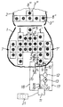
- a seat of a motor vehicle is shown in simplified form with a view of the surface of the seat part 1 and the lower region of the backrest 2.
- an elastic mat divided into a plurality of hollow chambers 3, 3 'and 3'',3''.
- Each hollow chamber has at least one upper elastic support wall, via which the pressure in the seat support surface of the seat user can be changed.
- reference numbers In order to maintain clarity, only some of the hollow chambers 3, 3 ', 3'',3''' are provided with reference numbers.
- five hollow chambers are arranged one behind the other in the two leg support surfaces 4, 4 '.
- a pressure sensor 8, 8 ', 8'',8''' is provided in each hollow chamber 3, 3 ', 3'',3''', for example below, above or in the upper hollow chamber wall of the respective hollow chamber 3, 3 ', 3'',3'' are arranged. For reasons of better clarity, only some of the pressure sensors 8, 8 ', 8'',8''' are provided with reference numbers. Based on the hollow chamber 3, it is given in a simplified manner below how the pressure in each of the hollow chambers 3, 3 ', 3'',3''' can be increased or decreased.
- each hollow chamber 3 ', 3'',3'' opens a pressure line 10 which can be closed by an inlet valve 9 and which can preferably be loaded with a constant pressure by a control device 11.
- a pressure accumulator 12 is arranged in the pressure line 10 and is to be charged by a pump 13 or the like, which draws in a gaseous or liquid medium, preferably air from the environment or, when the control device is designed, as a closed system from a low pressure accumulator.
- an outlet line closable by an outlet valve 14 opens into each of the hollow chambers 3, 3 ', 3'',3''' 15, which is connected to the relaxed medium or the ambient air or a low pressure accumulator.
- the direction of inflow and outflow is indicated by the arrows.
- the pressure sensors 8, 8 ', 8'',8'' are each connected to the control device 11 via a pressure detection line 16.
- all inlet valves 9 are each connected via a control line 17 and all outlet valves 14 via a control line 18 to the control device 11 and can be actuated by the latter in order to open or close the relevant inlet 9 or outlet valve 14.
- the pressure accumulator 12 is also connected to the control device 11 via a line 19 and the pump 13 via a line 20.
- Setpoint pressure values for all hollow chambers 3, 3 ′, 3 ′′, 3 ′′ ′′ are entered in the control device or a data memory thereof, or manually entered and stored by the seat user via control elements 21.
- all hollow chambers 3, 3 ', 3'''' are continuously or after predetermined or adjustable periods of time simultaneously by detecting the respective pressures in the hollow chambers 3, 3', 3 '', 3 ''' the pressure transducers 8, 8 ', 8'',8''' and comparing the stored target pressure values with a readjustment of the pressure in question in the respective hollow chamber 3, 3 ', 3'',3''' until the measured pressures approximately agree with the respective target pressure values.
- the setpoint pressure values are or are set by the control device 11 to such values that a fatigue-free sitting without excessive local pressure load is possible. Maximum pressure loads for the respective hollow chambers 3, 3 ', 3'',3''' are entered in the control device 11 and are not exceeded.
- the control device can also have a device, for example electronics, which detects the constitution and / or seat movements of a seat user via sensors and automatically determines new setpoint pressure values therefrom which are decisive for the control process.
- a device for example electronics, which detects the constitution and / or seat movements of a seat user via sensors and automatically determines new setpoint pressure values therefrom which are decisive for the control process.
- stored pressure distributions and possibly pressure distributions previously set by a specific seat user for setpoint pressure values are taken into account.
- all pressure transducers 8, 8 ', 8'',8''' are hydrosensors with piezoresistive pressure sensors embedded in liquid, which detect the pressure in the liquid regardless of the direction.
- the pressure sensors have, for example, a diameter of 20 mm and a thickness of approximately 2 to 3 mm, which are embedded in the mat having the hollow chambers.
- variable pressure Hollow chambers 3 '', 3 '''in the backrest 2 the pressure load on the spine of a seat user can be changed favorably.
- outer hollow chambers 8 ′′ a lateral back support is effected during lateral acceleration, for example when cornering. Lateral support of the legs of the seat user, for example when cornering, is effected via the hollow chambers arranged in the side regions 7, 7 '.
- the invention can also be implemented differently from the exemplary embodiment.
- the hollow chambers can only be provided in the seat part of a seat user or, as in the exemplary embodiment, also on the backrest.
- the distribution and size of the hollow chambers is arbitrary in itself.
- Each hollow chamber is preferably provided with a pressure sensor. However, other hollow chambers can also be provided, which cannot be changed in pressure and therefore do not have an associated pressure sensor.
- the inlet and outlet valve can be any valve that is connected, for example, to a common valve. Air or another gaseous or liquid medium can be taken up from each hollow chamber concerned. It is essential that the hollow chamber has an elastic support wall, at least in the area of the seat surface, via which the pressure acting in the seat support surface of the seat user can be changed locally by changing the pressure in the hollow chamber.
Abstract
Description
Die Erfindung betrifft einen Sitz mit druckveränderlichen Hohlkammern, mit den im Oberbegriff des Patentanspruches 1 angegebenen Merkmalen.The invention relates to a seat with pressure-variable hollow chambers, with the features specified in the preamble of
Ein derartiger Sitz ist durch die DE 35 41 537 A1 bekannt, der im Sitz- und Lehnenbereich mehrere Luftkammern aufweist, die zur Einstellung einer bestimmten Körperdruckverteilung unterschiedliche Druckwerte aufweisen können. In jede Luftkammer mündet eine Pneumatikleitung, die von einem Ventil verschließbar ist und einerseits mit einer Druckleitung und andererseits mit einer Auslaßleitung verbunden ist, in der sich ein Ablaßventil befindet. In einer von der Druckleitung abzweigenden Nebenleitung ist ein einziger Drucksensor angeordnet, der durch aufeinanderfolgendes Verbinden dieser Nebenleitung mit der jeweiligen Luftkammer die Bestimmung des Luftdrucks in dieser Luftkammer ermöglicht. Bei dieser Anordnung ist es nicht möglich, gleichzeitig in einer Luftkammer den Luftdruck zu erhöhen und in einer beliebigen anderen Kammer zu erniedrigen. Die Druckleitung kann nicht kostengünstig von einem Druckspeicher mit konstantem Druck belastet sein, da beim Öffnen des Ablaßventiles in der Auslaßleitung der Druck in der Druckleitung schlagartig abfällt. Mit dem einzigen Drucksensor ist die wechselseitige Druckbeeinflussung der Luftkammern untereinander nicht zu erfassen bzw. zu berücksichtigen. In der Sitzfläche sind lediglich wenige Luftkammern vorgesehen, die bei den lokal unterschiedlichen Flächenbelastungen durch den Sitzbenutzer keine gezielte Druckentlastung beispielsweise in einem Flächenbereich mit besonders hoher Flächenpressung ermöglichen.Such a seat is known from DE 35 41 537 A1, which has a plurality of air chambers in the seat and backrest area, which can have different pressure values for setting a specific body pressure distribution. A pneumatic line opens into each air chamber, which can be closed by a valve and is connected on the one hand to a pressure line and on the other hand to an outlet line in which a drain valve is located. A single pressure sensor is arranged in a branch line branching off from the pressure line and enables the air pressure in this air chamber to be determined by successively connecting this branch line to the respective air chamber. With this arrangement, it is not possible to simultaneously increase the air pressure in one air chamber and to lower it in any other chamber. The pressure line cannot be loaded cost-effectively by a pressure accumulator with constant pressure, since when the drain valve in the outlet line opens, the pressure in the pressure line drops suddenly. With the single pressure sensor, the mutual influence of the air chambers on one another cannot be detected or taken into account. Only a few air chambers are provided in the seat, which are subject to the locally different surface loads by the seat user do not allow targeted pressure relief, for example in a surface area with a particularly high surface pressure.
Ein ähnlicher Fahrzeugsitz ist in der DE 40 22 433 C2 beschrieben, bei dem die Luftkammern mit einem an- und abschwellenden Druck belastbar sind, um eine Massagewirkung zu erreichen.A similar vehicle seat is described in DE 40 22 433 C2, in which the air chambers can be loaded with a rising and falling pressure in order to achieve a massage effect.
Der Erfindung liegt die Aufgabe zugrunde, einen Sitz mit den im Oberbegriff des Patentanspruches 1 angegebenen Merkmalen anzugeben, der an den von dem Sitzbenutzer belasteten Sitzflächenbereichen eine lokale Druckveränderung ermöglicht.The invention has for its object to provide a seat with the features specified in the preamble of
Diese Aufgabe ist durch die im Patentanspruch 1 angegebenen Merkmale gelöst. Durch die Anordnung von mehreren, zumindest mit einer elastischen Stützwand versehenen Hohlkammern mit Druckaufnehmern sowohl in Längsrichtung der Schenkelauflageflächen als auch im Gesäßauflagebereich kann an den stark belasteten Sitzflächenbereichen der Druck in den betreffenden Hohlkammern abgesenkt werden, wodurch sich die Flächenpressung an der Körperoberfläche des Sitzbenutzers entsprechend vermindert. Bei lediglich gering belasteten Flächen kann der Druck in den betreffenden Hohlkammern erhöht werden, um eine gleichmäßigere Flächenbelastung zu erreichen. Der Sitzkomfort wird dadurch wesentlich verbessert. Der Blutkreislauf des Sitzbenutzers kann mit einer alternierenden, beispielsweise wellenförmig fortschreitenden Druckveränderung in den einzelnen Kammern angeregt werden, beispielsweise um eine Ermüdung des Sitzbenutzers zu vermeiden. Nachdem in jede Hohlkammer eine über ein Ventil verschließbare Druckleitung und eine von einem Ventil verschließbare Auslaßleitung mündet, können einzelne oder mehrere Hohlkammern gleichzeitig mit Druckluft und andere Hohlkammern zur Druckabsenkung mit einer Auslaßleitung verbunden werden, wobei über die Druckaufnehmer in den Hohlkammern die Wechselwirkungen der unterschiedlichen Drücke in den Hohlkammern erfaßt und bei Abweichungen sofort korrigiert werden.This object is achieved by the features specified in
Vorteilhafte Ausgestaltungen der Erfindung sind Gegenstand von Unteransprüchen.Advantageous embodiments of the invention are the subject of dependent claims.
Ein Ausführungsbeispiel der Erfindung wird anhand einer Zeichnung mit einer einzigen Figur näher erläutert, die eine Prinzipskizze darstellt.An embodiment of the invention will be explained in more detail with reference to a drawing with a single figure, which represents a schematic diagram.
In der einzigen Figur ist ein Sitz eines Kraftfahrzeugs mit Blick auf die Oberfläche des Sitzteiles 1 und den unteren Bereich der Rückenlehne 2 vereinfacht dargestellt. Unter der Klimazone des Sitzteiles 1 und der Rückenlehne 2 ist jeweils eine in mehrere Hohlkammern 3, 3' und 3'', 3''' aufgeteilte elastische Matte gelegt. Jede Hohlkammer weist zumindest eine obere elastische Stützwand auf, über die der Druck in der Sitzauflagefläche des Sitzbenutzers veränderlich ist. Um die Übersichtlichkeit zu wahren, sind lediglich einige der Hohlkammern 3, 3', 3'', 3''' mit Bezugszahlen versehen. Wie sich aus der Figur ergibt, sind in den beiden Schenkeauflageflächen 4, 4' jeweils fünf Hohlkammern hintereinander angeordnet. Im Steißbeinbereich 5 eines Sitzbenutzers ist eine weitere Hohlkammer und davor im Gesäßauflagebereich 6 sind weitere neun Hohlkammern etwa gitterartig angeordnet. Zur seitlichen Stütze sind seitlich außen in einem Seitenbereich 7, 7' der Schenkelauflageflächen 4, 4' jeweils drei weitere Hohlkammern hintereinander angeordnet. Etwa im Lendenbereich der Rückenlehne 2 sind horizontal nebeneinander fünf Hohlkammern vorgesehen, wobei sich über der im Wirbelsäulenbereich des Sitzbenutzers befindlichen Hohlkammer eine weitere Hohlkammer 3''' befindet. In jeder Hohlkammer 3, 3', 3'', 3''' ist ein Druckaufnehmer 8, 8', 8'', 8''' vorgesehen, die beispielsweise unterhalb, oberhalb oder in der oberen Hohlkammerwand der betreffenden Hohlkammer 3, 3', 3'', 3''' angeordnet sind. Aus Gründen einer besseren Übersichtlichkeit sind lediglich einige der Druckaufnehmer 8, 8', 8'', 8''' mit Bezugszahlen versehen. Anhand der Hohlkammer 3 wird nachfolgend vereinfacht angegeben, wie der Druck in jeder der Hohlkammern 3, 3', 3'', 3''' erhöht oder erniedrigt werden kann. In jede Hohlkammer 3, 3', 3'', 3''' mündet eine von einem Einlaßventil 9 verschließbare Druckleitung 10, die von einer Regelungseinrichtung 11 vorzugsweise mit konstantem Druck belastbar ist. Hierzu ist in der Druckleitung 10 ein Druckspeicher 12 angeordnet, der von einer Pumpe 13 oder dergleichen aufzuladen ist, die ein gasförmiges oder flüssiges Medium, vorzugsweise Luft aus der Umgebung oder bei Ausbildung der Regelungseinrichtung als geschlossenes System aus einem Niederdruckspeicher ansaugt. Außerdem mündet in jede der Hohlkammern 3, 3', 3'', 3''' eine von einem Auslaßventil 14 verschließbare Auslaßleitung 15, die mit dem entspannten Medium bzw. der Umgebungsluft oder einem Niederdruckspeicher verbunden ist. Durch die Pfeile ist die Zufluß- und Abflußrichtung angegeben. Die Druckaufnehmer 8, 8', 8'', 8''' sind jeweils über eine Druckerfassungsleitung 16 mit der Regelungseinrichtung 11 verbunden. Außerdem sind alle Einlaßventile 9 über jeweils eine Steuerleitung 17 und alle Auslaßventile 14 über jeweils eine Steuerleitung 18 mit der Regelungseinrichtung 11 verbunden und von dieser ansteuerbar, um das betreffende Einlaß- 9 bzw. Auslaßventil 14 zu öffnen bzw. zu schließen. An die Regelungseinrichtung 11 sind des weiteren der Druckspeicher 12 über eine Leitung 19 und die Pumpe 13 über eine Leitung 20 angeschlossen. In der Regelungseinrichtung bzw. einem Datenspeicher davon sind Soll-Druckwerte für alle Hohlkammern 3, 3', 3'', 3''' eingegeben bzw. über Bedienelemente 21 von dem Sitzbenutzer manuell einzugeben und zu speichern. Im Fahrbetrieb erfolgt ständig oder nach vorgegebenen bzw. einstellbaren Zeiträumen für alle Hohlkammern 3, 3', 3'', 3''' gleichzeitig durch Erfassung der jeweiligen Drücke in den Hohlkammern 3, 3', 3'', 3''' über die Druckaufnehmer 8, 8', 8'', 8''' und Vergleich mit den gespeicherten Soll-Druckwerten eine Nachregulierung des betreffenden Drucks in der jeweiligen Hohlkammer 3, 3', 3'', 3''', bis die gemessenen Drücke etwa mit den jeweiligen Soll-Druckwerten übereinstimmen. Die Soll-Druckwerte sind oder werden von der Regelungseinrichtung 11 auf solche Werte eingestellt, daß ein ermüdungsfreies Sitzen ohne übermäßige örtliche Druckbelastung möglich ist. In der Regelungseinrichtung 11 sind maximale Druckbelastungen für die jeweiligen Hohlkammern 3, 3', 3'', 3''' eingegeben, die nicht überschritten werden. Die Regelungseinrichtung kann auch eine Einrichtung, beispielsweise eine Elektronik, aufweisen, die über Sensoren die Konstitution und/oder Sitzbewegungen eines Sitzbenutzers erfaßt und daraus selbsttätig neue Soll-Druckwerte ermittelt, die für den Regelungsvorgang maßgebend sind. Bei der selbsttätigen Bestimmung der Soll-Druckwerte durch die Regelungseinrichtung werden gespeicherte Druckverteilungen und eventuell von einem bestimmten Sitzbenutzer früher eingestellte Druckverteilungen für Soll-Druckwerte berücksichtigt. Bei dem Ausführungsbeispiel sind alle Druckaufnehmer 8, 8', 8'', 8''' Hydrosensoren mit in Flüssigkeit eingebetteten piezoresistiven Drucksensoren, die den Druck in der Flüssigkeit richtungsunabhängig erfassen. Die Drucksensoren weisen beispielsweise einen Durchmesser von 20 mm und eine Dicke von ca. 2 bis 3 mm auf, die in der die Hohlkammern aufweisenden Matte eingebettet sind. Mit den druckveränderlichen Hohlkammern 3'', 3''' in der Rückenlehne 2 kann die Druckbelastung an der Wirbelsäule eines Sitzbenutzers günstig verändert werden. Mit den äußeren Hohlkammern 8'' wird bei Seitenbeschleunigungen beispielsweise bei Kurvenfahrt eine seitliche Rückenstütze bewirkt. Eine seitliche Stütze der Schenkel des Sitzbenutzers, beispielsweise bei Kurvenfahrt, wird über die in den Seitenbereichen 7, 7' angeordneten Hohlkammern bewirkt.In the single figure, a seat of a motor vehicle is shown in simplified form with a view of the surface of the
Die Erfindung kann auch von dem Ausführungsbeispiel abweichend ausgeführt werden. Die Hohlkammern können lediglich im Sitzteil eines Sitzbenutzers oder wie bei dem Ausführungsbeispiel auch an der Rückenlehne vorgesehen sein. Die Verteilung und Größe der Hohlkammern ist an sich beliebig. Vorzugsweise ist jede Hohlkammer mit einem Druckaufnehmer versehen. Es können aber auch andere Hohlkammern vorgesehen sein, die nicht druckveränderlich sind und deshalb keinen zugeordneten Druckaufnehmer aufweisen. Das Einlaß- und Auslaßventil können beliebige Ventile sein, die beispielsweise zu einem gemeinsamen Ventil verbunden sind. Von jeder betreffenden Hohlkammer kann Luft oder ein anderes gasförmiges oder flüssiges Medium aufgenommen sein. Wesentlich ist, daß die Hohlkammer zumindest im Sitzflächenbereich eine elastische Stützwand aufweist, über die durch Druckveränderung in der Hohlkammer der in der Sitzauflagefläche des Sitzbenutzers wirkende Druck lokal veränderlich ist.The invention can also be implemented differently from the exemplary embodiment. The hollow chambers can only be provided in the seat part of a seat user or, as in the exemplary embodiment, also on the backrest. The distribution and size of the hollow chambers is arbitrary in itself. Each hollow chamber is preferably provided with a pressure sensor. However, other hollow chambers can also be provided, which cannot be changed in pressure and therefore do not have an associated pressure sensor. The inlet and outlet valve can be any valve that is connected, for example, to a common valve. Air or another gaseous or liquid medium can be taken up from each hollow chamber concerned. It is essential that the hollow chamber has an elastic support wall, at least in the area of the seat surface, via which the pressure acting in the seat support surface of the seat user can be changed locally by changing the pressure in the hollow chamber.
Claims (9)
Applications Claiming Priority (2)
| Application Number | Priority Date | Filing Date | Title |
|---|---|---|---|
| DE19545168A DE19545168A1 (en) | 1995-12-04 | 1995-12-04 | Seat with variable pressure hollow chambers that have an elastic support wall |
| DE19545168 | 1995-12-04 |
Publications (2)
| Publication Number | Publication Date |
|---|---|
| EP0778173A2 true EP0778173A2 (en) | 1997-06-11 |
| EP0778173A3 EP0778173A3 (en) | 1998-12-02 |
Family
ID=7779128
Family Applications (1)
| Application Number | Title | Priority Date | Filing Date |
|---|---|---|---|
| EP96119277A Ceased EP0778173A3 (en) | 1995-12-04 | 1996-12-02 | Seat with variable pressure cavities, which have a flexible support wall |
Country Status (2)
| Country | Link |
|---|---|
| EP (1) | EP0778173A3 (en) |
| DE (1) | DE19545168A1 (en) |
Cited By (3)
| Publication number | Priority date | Publication date | Assignee | Title |
|---|---|---|---|---|
| CN101211190B (en) * | 2006-12-25 | 2010-05-19 | 财团法人工业技术研究院 | Mobile device |
| CN107089170A (en) * | 2017-04-19 | 2017-08-25 | 京东方科技集团股份有限公司 | Seat system |
| WO2018224631A1 (en) * | 2017-06-08 | 2018-12-13 | Volkswagen Aktiengesellschaft | Configuration of a massage program for a massage device of a vehicle seat |
Families Citing this family (14)
| Publication number | Priority date | Publication date | Assignee | Title |
|---|---|---|---|---|
| WO1999030934A1 (en) * | 1997-12-17 | 1999-06-24 | Siemens Aktiengesellschaft | Controller for a vehicle passenger protection means |
| DE10106918A1 (en) * | 2001-02-15 | 2002-08-22 | Bayerische Motoren Werke Ag | Vehicle seat with adjustable cushioning, especially for motor cycles, has elastically deformable hollow bodies embedded in cushioning, connected via hoses to pump that can apply pressurized medium |
| DE10139412B4 (en) * | 2001-08-17 | 2005-03-10 | Isringhausen Geb | Vehicle seat with active contour adjustment |
| DE10242760B4 (en) * | 2002-09-14 | 2007-10-04 | Daimlerchrysler Ag | Vehicle seat with massage function and contour adjustment |
| DE102006045726A1 (en) * | 2006-09-27 | 2008-04-03 | Müller, Ralf, Dr. med. | Vehicle or office seat for stabilizing the lumbar vertebral column of a person when sitting has a reshapable support for matching the contour of a person sitting on the seat |
| DE102007053119A1 (en) * | 2007-11-08 | 2009-05-14 | Bayerische Motoren Werke Aktiengesellschaft | Method and device for adjusting a seat and seat |
| DE102009028846A1 (en) | 2008-08-28 | 2010-03-04 | C. Rob. Hammerstein Gmbh & Co. Kg | Cushion body for motor vehicle seat, has hollow chambers provided adjacent to each other and filled with fluid i.e. gas, under pressure, where hollow chambers are connected with one another in fluid-moderate manner via passages |
| DE102009016050A1 (en) * | 2009-04-02 | 2010-10-07 | Bayerische Motoren Werke Aktiengesellschaft | Pad for a seat |
| DE102009021532A1 (en) * | 2009-05-15 | 2010-11-18 | Nitring Enterprise Inc. | Vehicle chair adjusting method, involves comparing pressure signals with pressure values, and adjusting air amount in pockets based on comparison result, where comparison and adjustment steps are performed until signals correspond to values |
| DE102009055049A1 (en) * | 2009-12-21 | 2012-02-02 | Robert Bosch Gmbh | Device and method for adapting the seat friction for a vehicle |
| DE102011102021A1 (en) | 2011-05-19 | 2012-11-22 | Daimler Ag | Method for operating seat of vehicle i.e. passenger car, involves adjusting integrated blisters from first condition to second condition that differs from first condition, where smaller force is exerted from blisters to seat occupant |
| DE102014207753B4 (en) | 2014-04-24 | 2018-02-15 | Bayerische Motoren Werke Aktiengesellschaft | Use of a vehicle seat for moving a child seat |
| US10391913B2 (en) | 2016-01-15 | 2019-08-27 | Ford Global Technologies, Llc | Method for dynamic adaptation of lateral support to vehicle states in motor vehicle seats with a seat surface and with a backrest and corresponding seat |
| DE102016004645A1 (en) * | 2016-04-16 | 2017-10-19 | Daimler Ag | Vehicle seat for a motor vehicle |
Citations (2)
| Publication number | Priority date | Publication date | Assignee | Title |
|---|---|---|---|---|
| DE3541537A1 (en) | 1984-12-13 | 1986-06-19 | Nhk Spring Co., Ltd., Yokohama, Kanagawa | PNEUMATICALLY CONTROLLED SEAT FOR A VEHICLE |
| DE4022433C2 (en) | 1989-07-14 | 1995-01-26 | Nissan Motor | Seat with anti-fatigue device |
Family Cites Families (15)
| Publication number | Priority date | Publication date | Assignee | Title |
|---|---|---|---|---|
| FR2192456A5 (en) * | 1972-07-13 | 1974-02-08 | Faure Bertrand Ets | |
| JPS5925709A (en) * | 1982-07-31 | 1984-02-09 | アイシン精機株式会社 | Air lamber support apparatus |
| JPS59230833A (en) * | 1983-06-14 | 1984-12-25 | Hitachi Ltd | Driver's seat |
| US4592588A (en) * | 1983-08-04 | 1986-06-03 | Tachikawa Spring Co., Ltd. | Vehicle seat |
| DE3432871A1 (en) * | 1984-09-07 | 1986-03-13 | Daimler-Benz Ag, 7000 Stuttgart | Method for acting on air cushions embedded in the upholstery of the seat of a motor vehicle and switching element for carrying out the method |
| US4615563A (en) * | 1984-11-09 | 1986-10-07 | Tachikawa Spring Co., Ltd. | Vehicle seat |
| US4920591A (en) * | 1985-07-16 | 1990-05-01 | Hiroshi Sekido | Air support for chair and method for manufacturing chair utilizing the air support |
| DE3804848A1 (en) * | 1988-02-17 | 1989-08-31 | Steinbrueck Peter | Control device for inflatable inlays |
| DE3804961C2 (en) * | 1988-02-18 | 2001-08-30 | Mannesmann Vdo Ag | Method for controlling the pressure in the air chambers of a seat |
| DE3839130C1 (en) * | 1988-11-19 | 1990-04-12 | Daimler-Benz Aktiengesellschaft, 7000 Stuttgart, De | Backrest for the seat of a motor vehicle |
| US5029939A (en) * | 1989-10-05 | 1991-07-09 | General Motors Corporation | Alternating pressure pad car seat |
| JPH04197315A (en) * | 1990-11-29 | 1992-07-16 | Nissan Motor Co Ltd | Seat |
| US5170364A (en) * | 1990-12-06 | 1992-12-08 | Biomechanics Corporation Of America | Feedback system for load bearing surface |
| JPH06237838A (en) * | 1993-02-02 | 1994-08-30 | Mccord Winn Textron Inc | Automatically programmable waist part system with memory |
| US5687099A (en) * | 1995-02-06 | 1997-11-11 | Gross; Clifford M. | Body support with adaptive pressurization |
-
1995
- 1995-12-04 DE DE19545168A patent/DE19545168A1/en not_active Withdrawn
-
1996
- 1996-12-02 EP EP96119277A patent/EP0778173A3/en not_active Ceased
Patent Citations (2)
| Publication number | Priority date | Publication date | Assignee | Title |
|---|---|---|---|---|
| DE3541537A1 (en) | 1984-12-13 | 1986-06-19 | Nhk Spring Co., Ltd., Yokohama, Kanagawa | PNEUMATICALLY CONTROLLED SEAT FOR A VEHICLE |
| DE4022433C2 (en) | 1989-07-14 | 1995-01-26 | Nissan Motor | Seat with anti-fatigue device |
Cited By (8)
| Publication number | Priority date | Publication date | Assignee | Title |
|---|---|---|---|---|
| CN101211190B (en) * | 2006-12-25 | 2010-05-19 | 财团法人工业技术研究院 | Mobile device |
| CN107089170A (en) * | 2017-04-19 | 2017-08-25 | 京东方科技集团股份有限公司 | Seat system |
| CN107089170B (en) * | 2017-04-19 | 2019-09-06 | 京东方科技集团股份有限公司 | Seat system |
| WO2018224631A1 (en) * | 2017-06-08 | 2018-12-13 | Volkswagen Aktiengesellschaft | Configuration of a massage program for a massage device of a vehicle seat |
| KR20190133269A (en) * | 2017-06-08 | 2019-12-02 | 폭스바겐 악티엔 게젤샤프트 | Composition of massage program for massage device of vehicle seat |
| CN110691715A (en) * | 2017-06-08 | 2020-01-14 | 大众汽车有限公司 | Arrangement of a massage program for a massage device of a vehicle seat |
| US11241989B2 (en) | 2017-06-08 | 2022-02-08 | Volkswagen Aktiengesellschaft | Configuration of a massage program for a massage device of a vehicle seat |
| CN110691715B (en) * | 2017-06-08 | 2022-06-14 | 大众汽车有限公司 | Arrangement of a massage program for a massage device of a vehicle seat |
Also Published As
| Publication number | Publication date |
|---|---|
| DE19545168A1 (en) | 1997-06-05 |
| EP0778173A3 (en) | 1998-12-02 |
Similar Documents
| Publication | Publication Date | Title |
|---|---|---|
| EP0778173A2 (en) | Seat with variable pressure cavities, which have a flexible support wall | |
| DE102018133307B4 (en) | Method for detecting fidgeting of a seat occupant for a seating arrangement | |
| DE102005038289B3 (en) | Method for detecting and changing a distribution of pressure on a sitting or lying arrangement caused by a human body and such a sitting or lying arrangement | |
| DE69920716T2 (en) | METHOD IN A SYSTEM FOR REGULATING THE COMFORT OF A SEAT WITH SEVERAL AIR CELLS THAT ARE INTERACTIVELY AND INDIVIDUALLY CONTROLLED. | |
| DE19750223C2 (en) | Method for adapting the side support of a seated person in a vehicle seat and vehicle seat for this purpose, based on the driving situation and driving style | |
| DE102016206626A1 (en) | Adjustable seating arrangement | |
| EP1072465B1 (en) | Vehicle seat with adjustable profile | |
| DE102015210497A1 (en) | Adjustable seating arrangement | |
| DE3541537A1 (en) | PNEUMATICALLY CONTROLLED SEAT FOR A VEHICLE | |
| DE102015210496A1 (en) | Adjustable seating arrangement | |
| DE4022423A1 (en) | SEAT WITH DEFENSE PREVENTION | |
| DE3804848A1 (en) | Control device for inflatable inlays | |
| DE102017214244A1 (en) | Seating arrangement with massage bubbles with a reduced number of pressure sensors | |
| DE102018207129B4 (en) | seating arrangement | |
| DE102017205135A1 (en) | Control device in a vehicle for driving a comfort function providing unit | |
| DE102017211172A1 (en) | Gradually adjustable seat assembly | |
| DE102016218158A1 (en) | Adjustable seating arrangement | |
| DE102018201662A1 (en) | ARRANGEMENT OF SPOOLING SUPPORT CHAMBERS | |
| DE112017005086T5 (en) | Vehicle seat device and air pressure control method for vehicle seat | |
| DE102018127003A1 (en) | VALVE MODULES FOR EXHAUSTABLE SEATS | |
| DE102006061502A1 (en) | Seat for a motor vehicle, motor vehicle with at least one seat and method for automated adjustment of a seat | |
| DE102017201871A1 (en) | Adjustable seat arrangement and vehicle arrangement | |
| DE112013004518T5 (en) | Body exercise device | |
| DE102010022020B4 (en) | Seat device and adjustment method | |
| DE102016219203A1 (en) | A method of air conditioning a vehicle seat and vehicle with such an air-conditioned vehicle seat |
Legal Events
| Date | Code | Title | Description |
|---|---|---|---|
| PUAI | Public reference made under article 153(3) epc to a published international application that has entered the european phase |
Free format text: ORIGINAL CODE: 0009012 |
|
| AK | Designated contracting states |
Kind code of ref document: A2 Designated state(s): DE FR GB IT |
|
| PUAL | Search report despatched |
Free format text: ORIGINAL CODE: 0009013 |
|
| AK | Designated contracting states |
Kind code of ref document: A3 Designated state(s): DE FR GB IT |
|
| 17P | Request for examination filed |
Effective date: 19990128 |
|
| 17Q | First examination report despatched |
Effective date: 19991201 |
|
| GRAG | Despatch of communication of intention to grant |
Free format text: ORIGINAL CODE: EPIDOS AGRA |
|
| STAA | Information on the status of an ep patent application or granted ep patent |
Free format text: STATUS: THE APPLICATION HAS BEEN REFUSED |
|
| 18R | Application refused |
Effective date: 20010617 |