EP0988424B1 - Modulare brücke - Google Patents
Modulare brücke Download PDFInfo
- Publication number
- EP0988424B1 EP0988424B1 EP98932046A EP98932046A EP0988424B1 EP 0988424 B1 EP0988424 B1 EP 0988424B1 EP 98932046 A EP98932046 A EP 98932046A EP 98932046 A EP98932046 A EP 98932046A EP 0988424 B1 EP0988424 B1 EP 0988424B1
- Authority
- EP
- European Patent Office
- Prior art keywords
- bridge
- lower chords
- short
- ramp
- modular
- Prior art date
- Legal status (The legal status is an assumption and is not a legal conclusion. Google has not performed a legal analysis and makes no representation as to the accuracy of the status listed.)
- Expired - Lifetime
Links
- 230000008878 coupling Effects 0.000 description 8
- 238000010168 coupling process Methods 0.000 description 8
- 238000005859 coupling reaction Methods 0.000 description 8
- 238000005452 bending Methods 0.000 description 1
- 230000001419 dependent effect Effects 0.000 description 1
Images

Classifications
-
- E—FIXED CONSTRUCTIONS
- E01—CONSTRUCTION OF ROADS, RAILWAYS, OR BRIDGES
- E01D—CONSTRUCTION OF BRIDGES, ELEVATED ROADWAYS OR VIADUCTS; ASSEMBLY OF BRIDGES
- E01D15/00—Movable or portable bridges; Floating bridges
- E01D15/12—Portable or sectional bridges
- E01D15/133—Portable or sectional bridges built-up from readily separable standardised sections or elements, e.g. Bailey bridges
Definitions
- the invention relates to a predominantly mobile modular bridge that can be coupled from at least two short bridges.
- a modular bridge is, for example, from US 5,526,544 A. previously known. However, there are the fixed lower chords ("lower chord 2") coupled together ("locking region 9"). An additional displaceable lower chord is not removable in US 5,526,544 A.
- the object of the invention is to provide a modular bridge that is as possible can be quickly built from existing short bridges.
- the modular bridge according to the invention (hereinafter also referred to as a long bridge referred to) is created by coupling two or more short ones together Bridges according to the features of claim 1.
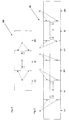
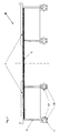
- the short bridges BK each of which represents a load-bearing structure, each comprise two bridge ramp sections BR and an inner bridge section BI (FIGS. 1 and 5, 7).
- the ramp sections BR are connected by means of joints G to the ends of the inner sections BI.
- the inner section BI and the ramp section BR each comprise two track carrier parts, each track carrier part comprising a roadway F and side walls S.
- the road slabs are also the top chord of the bending beam.
- the individual track carrier parts of the inner sections BI are connected to one another by means of cross members Q.
- the bridge sections BI, BR have lower chords U which are firmly connected to the side walls S and which, in the example outlined, have the shape of an inverted u (FIG. 7).
- each of the four U-shaped fixed lower chords U there is a movable lower chord UB which can be moved in the direction of the bridge span and which also has coupling points corresponding to the coupling points of the fixed lower chords U.
- the fixed lower chords U of the individual bridge sections are connected to one another via the displaceable lower chord UB as a flap, the displaceable lower chord UB bearing according to its rigidity.
- the coupling is designed in the form of an eye rod connection by means of bolts BZ (FIG. 7).
- the displaceable lower flange UB which is shown in the embodiment according to FIGS.
- 1 to 4 as a single component can also be designed in several sections that can be displaced independently of one another. This applies in particular to those designs in which the lengths of ramp sections BR and inner sections BI are different or in which more than two short bridges are connected to form a long bridge.
- a load-bearing long bridge BL is created of double length, as shown in Fig. 4.
- the invention is not based on the embodiment of the long one shown in FIGS Bridge limited by exactly two short bridges. Rather, according to the invention any number of short bridges to one long bridge be coupled together. Both parts of the ramp become the inside short bridges swiveled upwards. Length and number of sliding Lower straps are adjusted accordingly.
Landscapes
- Engineering & Computer Science (AREA)
- Architecture (AREA)
- Civil Engineering (AREA)
- Structural Engineering (AREA)
- Bridges Or Land Bridges (AREA)
Description
- Fig. 1
- eine kurze Brücke, eingerichtet zum Befahren,
- Fig. 2
- eine kurze Brücke, rechter Rampenabschnitt hochgeschwenkt, verschiebbarer Untergurt nach rechts verschoben (der verschiebbare Untergurt ist zusätzlich getrennt dargestellt),
- Fig. 3
- eine kurze Brücke, linker Rampenabschnitt hochgeschwenkt, verschiebbarer Untergurt nach links verschoben (der verschiebbare Untergurt ist zusätzlich getrennt dargestellt),
- Fig. 4
- eine lange Brücke aus zwei kurzen Brücken, gegenüberliegende Rampenabschnitte hochgeschwenkt und an den Rampenspitzen gekoppelt, verschiebbare Untergurte aufeinanderzu verschoben und gekoppelt (der verschiebbare Untergurt ist zusätzlich getrennt dargestellt),
- Fig. 5
- eine kurze Brücke, Ansicht von oben,
- Fig. 6
- eine lange Brücke aus zwei kurzen Brücken, Ansicht von oben,
- Fig. 7
- den Querschnitt durch den Innenabschnitt einer Brücke.
Der verschiebbare Untergurt UB, der in der Ausführung nach Fig. 1 bis 4 als ein einzelnes Bauteil dargestellt ist, kann auch in mehrere Abschnitte, die unabhängig voneinander verschiebbar sind, ausgeführt sein. Das trifft insbesondere für solche Ausführungen zu, bei denen die Längen von Rampenabschnitten BR und Innenabschnitten BI unterschiedlich sind oder bei denen mehr als zwei kurze Brücken zu einer langen Brücke verbunden werden.
Claims (6)
- Modulare Brücke (BL), welche durch mindestens zwei zusammengekuppelte kurze Brücken (BK) entsteht, wobei eine kurze Brücke (BK) in Brückenspannweitenrichtung folgende Bauteile aufweist:und die kurzen Brücken (BK) an den Rampenspitzen (RS) der nach oben verschwenkten Brückenrampenabschnitte (BR) und den verschobenen Untergurten (UB) zusammengekuppelt sind.einen Brückeninnenabschnitt (BI), rechts und links davonzwei im Einbauzustand nach oben verschwenkbare Brückenrampenabschnitte (BR),fest mit dem Brückeninnenabschnitt (BI) und den Brückenrampenabschnitten (BR) verbundene Untergurte (U),in Bezug auf die fest verbundenen Untergurte (U) in Brückenspannweitenrichtung verschiebbare Untergurte (UB),
- Modulare Brücke (BL) nach Anspruch 1, dadurch gekennzeichnet, daß die mit den Rampenspitzen fest verbundenen Untergurte (U) der nach oben verschwenkten Brückenrampenabschnitte (BR) der kurzen Brücken (BK) Diagonalstreben der zusammengekuppelten Brücke (BL) bilden.
- Modulare Brücke (BL) nach Anspruch 1 oder 2, dadurch gekennzeichnet, daß die verschobenen Untergurte (UB) der kurzen Brücken (BK) Untergurte der zusammengekuppelten Brücke (BL) bilden.
- Modulare Brücke (BL) nach einem der vorangehenden Ansprüche, dadurch gekennzeichnet, daß die fest verbundenen Untergurte (U) einen U-förmigen Querschnitt aufweisen, in dem sich die verschiebbaren Untergurte (UB) befinden.
- Modulare Brücke (BL) nach einem der vorangehenden Ansprüche, dadurch gekennzeichnet, daß die fest verbundenen Untergurte (U) der nach oben verschwenkten Brückenrampenabschnitte (BR) mit den verschobenen Untergurten (UB) zusammengekuppelt sind.
- Modulare Brücke (BL) nach einem der vorangehenden Ansprüche, dadurch gekennzeichnet, daß ein verschiebbarer Untergurt (UB) aus mehreren, unabhängig voneinander verschiebbaren Abschnitten besteht.
Applications Claiming Priority (3)
| Application Number | Priority Date | Filing Date | Title |
|---|---|---|---|
| DE19724771A DE19724771C1 (de) | 1997-06-12 | 1997-06-12 | Modulare Brücke |
| DE19724771 | 1997-06-12 | ||
| PCT/DE1998/001214 WO1998056994A1 (de) | 1997-06-12 | 1998-05-02 | Modulare brücke |
Publications (2)
| Publication Number | Publication Date |
|---|---|
| EP0988424A1 EP0988424A1 (de) | 2000-03-29 |
| EP0988424B1 true EP0988424B1 (de) | 2002-04-03 |
Family
ID=7832232
Family Applications (1)
| Application Number | Title | Priority Date | Filing Date |
|---|---|---|---|
| EP98932046A Expired - Lifetime EP0988424B1 (de) | 1997-06-12 | 1998-05-02 | Modulare brücke |
Country Status (5)
| Country | Link |
|---|---|
| EP (1) | EP0988424B1 (de) |
| JP (1) | JP3849806B2 (de) |
| KR (1) | KR20010012204A (de) |
| DE (2) | DE19724771C1 (de) |
| WO (1) | WO1998056994A1 (de) |
Cited By (3)
| Publication number | Priority date | Publication date | Assignee | Title |
|---|---|---|---|---|
| EP1584748A2 (de) | 2004-04-07 | 2005-10-12 | Rheinmetall Landsysteme GmbH | Brückenverlegeeinrichtung |
| EP1584749A2 (de) | 2004-04-07 | 2005-10-12 | Rheinmetall Landsysteme GmbH | Brückenlegeeinheit |
| DE102007001778B3 (de) * | 2007-01-05 | 2008-05-29 | Rheinmetall Landsysteme Gmbh | Brückenlegefahrzeug |
Families Citing this family (4)
| Publication number | Priority date | Publication date | Assignee | Title |
|---|---|---|---|---|
| DE10307858B3 (de) * | 2003-02-25 | 2004-06-09 | Dornier Gmbh | Zerlegbare Brücke |
| GB2533817A (en) * | 2015-01-05 | 2016-07-06 | Bae Systems Plc | Mobile bridge module |
| GB2533818B (en) | 2015-01-05 | 2021-03-03 | Bae Systems Plc | Mobile bridge apparatus |
| CN107190629A (zh) * | 2017-06-05 | 2017-09-22 | 浙江省送变电工程公司 | 一种跨电缆沟可调节便桥 |
Family Cites Families (5)
| Publication number | Priority date | Publication date | Assignee | Title |
|---|---|---|---|---|
| DE3911266A1 (de) * | 1989-04-07 | 1990-10-11 | Krupp Industrietech | Verlegbare bruecke und system zum verlegen der bruecke |
| DE4209316A1 (de) * | 1992-03-23 | 1993-09-30 | Krupp Industrietech | Verlegbare Brücke |
| DE4305764A1 (de) * | 1993-02-25 | 1994-09-01 | Krupp Foerdertechnik Gmbh | Verlegbare Brücke und Einrichtung zum Verlegen der Brücke |
| EP0640722A1 (de) * | 1993-08-31 | 1995-03-01 | Krupp Fördertechnik GmbH | Verlegbare Brücke |
| DE4439844A1 (de) * | 1994-11-08 | 1996-05-30 | Krupp Foerdertechnik Gmbh | Vorrichtung zum automatischen Kuppeln von transportablen bzw. zerlegbaren Brücken |
-
1997
- 1997-06-12 DE DE19724771A patent/DE19724771C1/de not_active Expired - Fee Related
-
1998
- 1998-05-02 EP EP98932046A patent/EP0988424B1/de not_active Expired - Lifetime
- 1998-05-02 JP JP50124799A patent/JP3849806B2/ja not_active Expired - Fee Related
- 1998-05-02 WO PCT/DE1998/001214 patent/WO1998056994A1/de not_active Ceased
- 1998-05-02 DE DE59803628T patent/DE59803628D1/de not_active Expired - Lifetime
- 1998-05-02 KR KR19997010153A patent/KR20010012204A/de not_active Withdrawn
Cited By (6)
| Publication number | Priority date | Publication date | Assignee | Title |
|---|---|---|---|---|
| EP1584748A2 (de) | 2004-04-07 | 2005-10-12 | Rheinmetall Landsysteme GmbH | Brückenverlegeeinrichtung |
| EP1584749A2 (de) | 2004-04-07 | 2005-10-12 | Rheinmetall Landsysteme GmbH | Brückenlegeeinheit |
| DE102004016974A1 (de) * | 2004-04-07 | 2005-11-03 | Rheinmetall Landsysteme Gmbh | Brückenlegeeinheit |
| DE102004016983A1 (de) * | 2004-04-07 | 2005-11-17 | Rheinmetall Landsysteme Gmbh | Brückenverlegeeinrichtung |
| DE102004016983B4 (de) * | 2004-04-07 | 2006-01-19 | Rheinmetall Landsysteme Gmbh | Brückenverlegeeinrichtung |
| DE102007001778B3 (de) * | 2007-01-05 | 2008-05-29 | Rheinmetall Landsysteme Gmbh | Brückenlegefahrzeug |
Also Published As
| Publication number | Publication date |
|---|---|
| KR20010012204A (de) | 2001-02-15 |
| JP2002508816A (ja) | 2002-03-19 |
| DE59803628D1 (de) | 2002-05-08 |
| EP0988424A1 (de) | 2000-03-29 |
| WO1998056994A1 (de) | 1998-12-17 |
| JP3849806B2 (ja) | 2006-11-22 |
| DE19724771C1 (de) | 1998-10-01 |
Similar Documents
| Publication | Publication Date | Title |
|---|---|---|
| DE69330706T2 (de) | Verfahren zum Verändern der Spurweite eines Schienenfahrzeuges, Schienenfahrzeug mit veränderlicher Spurweite und zugehörige Bodeneinrichtung | |
| EP2288765A2 (de) | Gittertragwerk | |
| DE4419203C2 (de) | Aus Längsträgerabschnitten, Querträgern und Fahrbahnplatten zusammengesetzte Brücke | |
| DE2459497A1 (de) | Transportable bruecke | |
| EP0391149B1 (de) | Verlegbare Brücke und System zum Verlegen der Brücke | |
| EP0612886B1 (de) | Verlegbare Brücke und Einrichtung zum Verlegen der Brücke | |
| DE68908893T2 (de) | Faltbare transportable brücke. | |
| EP0988424B1 (de) | Modulare brücke | |
| EP3287305B1 (de) | Scherengestell und übergang mit scherengestell | |
| EP1915316B1 (de) | Faltbarer ausleger | |
| DE2217151B1 (de) | Vorrichtung zum ueberbruecken von dehnungsfugen in bruecken, strassen od. dgl | |
| WO1993019974A1 (de) | Spurbreitenveränderliches fahrwerk | |
| DE2047400A1 (de) | Befbrderungseinnchtung | |
| DE1680207C3 (de) | Kraftfahrzeug mit einer vorrichtung zum transportieren und verlegen einer mit auffahrrampen versehenen klappbruecke | |
| DE3400703C2 (de) | Konvergent-divergente Düse, insbesondere für ein Strahltriebwerk | |
| EP0916769A1 (de) | Brückenelement zur Bildung von mittels eines Verlegefahrzeugs verlegbaren Brücken | |
| EP0541948B1 (de) | Brücke | |
| DE1658621A1 (de) | Kraftfahrzeug mit einer Vorrichtung zum Transportieren und Verlegen einer mit Auffahrrampen versehenen Klappbruecke | |
| DE60117795T2 (de) | Einheit für den kombinierten Schienen/Strassentransport mit einer Vorrichtung zur Fixierung des Abstandes zwischen den endseitigen Plattformen während des Be-und/oder Entladens | |
| EP0566941B1 (de) | Hydraulische Druck- und Ziehvorrichtung, insbesondere für Eisenbahnschienen | |
| DE29824867U1 (de) | Kran mit einem Teleskopausleger | |
| EP0562338B1 (de) | Verlegbare Brücke | |
| DE102020105297A1 (de) | Amphibisches Brückenfahrzeug und Anordnung amphibischer Brückenfahrzeuge | |
| DE2641257C2 (de) | Fahrzeug mit ablegbarer Rampe zum Bilden von Brücken, insbesondere Schwimmbrücken und Fähren | |
| EP3141661B1 (de) | Brücke |
Legal Events
| Date | Code | Title | Description |
|---|---|---|---|
| PUAI | Public reference made under article 153(3) epc to a published international application that has entered the european phase |
Free format text: ORIGINAL CODE: 0009012 |
|
| 17P | Request for examination filed |
Effective date: 19991021 |
|
| AK | Designated contracting states |
Kind code of ref document: A1 Designated state(s): DE FR GB NL SE |
|
| GRAG | Despatch of communication of intention to grant |
Free format text: ORIGINAL CODE: EPIDOS AGRA |
|
| 17Q | First examination report despatched |
Effective date: 20010410 |
|
| GRAG | Despatch of communication of intention to grant |
Free format text: ORIGINAL CODE: EPIDOS AGRA |
|
| GRAH | Despatch of communication of intention to grant a patent |
Free format text: ORIGINAL CODE: EPIDOS IGRA |
|
| GRAH | Despatch of communication of intention to grant a patent |
Free format text: ORIGINAL CODE: EPIDOS IGRA |
|
| REG | Reference to a national code |
Ref country code: GB Ref legal event code: IF02 |
|
| GRAA | (expected) grant |
Free format text: ORIGINAL CODE: 0009210 |
|
| AK | Designated contracting states |
Kind code of ref document: B1 Designated state(s): DE FR GB NL SE |
|
| PGFP | Annual fee paid to national office [announced via postgrant information from national office to epo] |
Ref country code: SE Payment date: 20020502 Year of fee payment: 5 |
|
| REF | Corresponds to: |
Ref document number: 59803628 Country of ref document: DE Date of ref document: 20020508 |
|
| GBT | Gb: translation of ep patent filed (gb section 77(6)(a)/1977) |
Effective date: 20020701 |
|
| PLBE | No opposition filed within time limit |
Free format text: ORIGINAL CODE: 0009261 |
|
| STAA | Information on the status of an ep patent application or granted ep patent |
Free format text: STATUS: NO OPPOSITION FILED WITHIN TIME LIMIT |
|
| 26N | No opposition filed |
Effective date: 20030106 |
|
| PG25 | Lapsed in a contracting state [announced via postgrant information from national office to epo] |
Ref country code: SE Free format text: LAPSE BECAUSE OF NON-PAYMENT OF DUE FEES Effective date: 20030503 |
|
| EUG | Se: european patent has lapsed | ||
| PGFP | Annual fee paid to national office [announced via postgrant information from national office to epo] |
Ref country code: NL Payment date: 20040429 Year of fee payment: 7 |
|
| REG | Reference to a national code |
Ref country code: GB Ref legal event code: 732E |
|
| NLS | Nl: assignments of ep-patents |
Owner name: EUROBRIDGE MOBILE BRUECKEN GMBH |
|
| REG | Reference to a national code |
Ref country code: FR Ref legal event code: TP |
|
| PG25 | Lapsed in a contracting state [announced via postgrant information from national office to epo] |
Ref country code: NL Free format text: LAPSE BECAUSE OF NON-PAYMENT OF DUE FEES Effective date: 20051201 |
|
| NLV4 | Nl: lapsed or anulled due to non-payment of the annual fee |
Effective date: 20051201 |
|
| REG | Reference to a national code |
Ref country code: GB Ref legal event code: 732E |
|
| PGFP | Annual fee paid to national office [announced via postgrant information from national office to epo] |
Ref country code: DE Payment date: 20120523 Year of fee payment: 15 |
|
| PGFP | Annual fee paid to national office [announced via postgrant information from national office to epo] |
Ref country code: FR Payment date: 20120601 Year of fee payment: 15 Ref country code: GB Payment date: 20120522 Year of fee payment: 15 |
|
| GBPC | Gb: european patent ceased through non-payment of renewal fee |
Effective date: 20130502 |
|
| PG25 | Lapsed in a contracting state [announced via postgrant information from national office to epo] |
Ref country code: DE Free format text: LAPSE BECAUSE OF NON-PAYMENT OF DUE FEES Effective date: 20131203 |
|
| REG | Reference to a national code |
Ref country code: FR Ref legal event code: ST Effective date: 20140131 |
|
| REG | Reference to a national code |
Ref country code: DE Ref legal event code: R119 Ref document number: 59803628 Country of ref document: DE Effective date: 20131203 |
|
| PG25 | Lapsed in a contracting state [announced via postgrant information from national office to epo] |
Ref country code: GB Free format text: LAPSE BECAUSE OF NON-PAYMENT OF DUE FEES Effective date: 20130502 |
|
| PG25 | Lapsed in a contracting state [announced via postgrant information from national office to epo] |
Ref country code: FR Free format text: LAPSE BECAUSE OF NON-PAYMENT OF DUE FEES Effective date: 20130531 |