EP0974873A2 - Magnetischer Träger, Zwei-Komponenten-Entwickler und Bildherstellungsverfahren - Google Patents
Magnetischer Träger, Zwei-Komponenten-Entwickler und Bildherstellungsverfahren Download PDFInfo
- Publication number
- EP0974873A2 EP0974873A2 EP99305786A EP99305786A EP0974873A2 EP 0974873 A2 EP0974873 A2 EP 0974873A2 EP 99305786 A EP99305786 A EP 99305786A EP 99305786 A EP99305786 A EP 99305786A EP 0974873 A2 EP0974873 A2 EP 0974873A2
- Authority
- EP
- European Patent Office
- Prior art keywords
- magnetic
- resin
- magnetic carrier
- toner
- fine particles
- Prior art date
- Legal status (The legal status is an assumption and is not a legal conclusion. Google has not performed a legal analysis and makes no representation as to the accuracy of the status listed.)
- Granted
Links
Images


Classifications
-
- G—PHYSICS
- G03—PHOTOGRAPHY; CINEMATOGRAPHY; ANALOGOUS TECHNIQUES USING WAVES OTHER THAN OPTICAL WAVES; ELECTROGRAPHY; HOLOGRAPHY
- G03G—ELECTROGRAPHY; ELECTROPHOTOGRAPHY; MAGNETOGRAPHY
- G03G9/00—Developers
- G03G9/08—Developers with toner particles
- G03G9/097—Plasticisers; Charge controlling agents
- G03G9/09708—Inorganic compounds
- G03G9/09716—Inorganic compounds treated with organic compounds
-
- G—PHYSICS
- G03—PHOTOGRAPHY; CINEMATOGRAPHY; ANALOGOUS TECHNIQUES USING WAVES OTHER THAN OPTICAL WAVES; ELECTROGRAPHY; HOLOGRAPHY
- G03G—ELECTROGRAPHY; ELECTROPHOTOGRAPHY; MAGNETOGRAPHY
- G03G9/00—Developers
- G03G9/08—Developers with toner particles
- G03G9/097—Plasticisers; Charge controlling agents
- G03G9/09708—Inorganic compounds
- G03G9/09725—Silicon-oxides; Silicates
-
- G—PHYSICS
- G03—PHOTOGRAPHY; CINEMATOGRAPHY; ANALOGOUS TECHNIQUES USING WAVES OTHER THAN OPTICAL WAVES; ELECTROGRAPHY; HOLOGRAPHY
- G03G—ELECTROGRAPHY; ELECTROPHOTOGRAPHY; MAGNETOGRAPHY
- G03G9/00—Developers
- G03G9/08—Developers with toner particles
- G03G9/10—Developers with toner particles characterised by carrier particles
- G03G9/107—Developers with toner particles characterised by carrier particles having magnetic components
- G03G9/1075—Structural characteristics of the carrier particles, e.g. shape or crystallographic structure
-
- G—PHYSICS
- G03—PHOTOGRAPHY; CINEMATOGRAPHY; ANALOGOUS TECHNIQUES USING WAVES OTHER THAN OPTICAL WAVES; ELECTROGRAPHY; HOLOGRAPHY
- G03G—ELECTROGRAPHY; ELECTROPHOTOGRAPHY; MAGNETOGRAPHY
- G03G9/00—Developers
- G03G9/08—Developers with toner particles
- G03G9/10—Developers with toner particles characterised by carrier particles
- G03G9/107—Developers with toner particles characterised by carrier particles having magnetic components
- G03G9/108—Ferrite carrier, e.g. magnetite
- G03G9/1085—Ferrite carrier, e.g. magnetite with non-ferrous metal oxide, e.g. MgO-Fe2O3
-
- G—PHYSICS
- G03—PHOTOGRAPHY; CINEMATOGRAPHY; ANALOGOUS TECHNIQUES USING WAVES OTHER THAN OPTICAL WAVES; ELECTROGRAPHY; HOLOGRAPHY
- G03G—ELECTROGRAPHY; ELECTROPHOTOGRAPHY; MAGNETOGRAPHY
- G03G9/00—Developers
- G03G9/08—Developers with toner particles
- G03G9/10—Developers with toner particles characterised by carrier particles
- G03G9/107—Developers with toner particles characterised by carrier particles having magnetic components
- G03G9/1088—Binder-type carrier
- G03G9/10882—Binder is obtained by reactions only involving carbon-carbon unsaturated bonds
-
- G—PHYSICS
- G03—PHOTOGRAPHY; CINEMATOGRAPHY; ANALOGOUS TECHNIQUES USING WAVES OTHER THAN OPTICAL WAVES; ELECTROGRAPHY; HOLOGRAPHY
- G03G—ELECTROGRAPHY; ELECTROPHOTOGRAPHY; MAGNETOGRAPHY
- G03G9/00—Developers
- G03G9/08—Developers with toner particles
- G03G9/10—Developers with toner particles characterised by carrier particles
- G03G9/107—Developers with toner particles characterised by carrier particles having magnetic components
- G03G9/1088—Binder-type carrier
- G03G9/10884—Binder is obtained other than by reactions only involving carbon-carbon unsaturated bonds
-
- G—PHYSICS
- G03—PHOTOGRAPHY; CINEMATOGRAPHY; ANALOGOUS TECHNIQUES USING WAVES OTHER THAN OPTICAL WAVES; ELECTROGRAPHY; HOLOGRAPHY
- G03G—ELECTROGRAPHY; ELECTROPHOTOGRAPHY; MAGNETOGRAPHY
- G03G9/00—Developers
- G03G9/08—Developers with toner particles
- G03G9/10—Developers with toner particles characterised by carrier particles
- G03G9/113—Developers with toner particles characterised by carrier particles having coatings applied thereto
- G03G9/1132—Macromolecular components of coatings
- G03G9/1133—Macromolecular components of coatings obtained by reactions only involving carbon-to-carbon unsaturated bonds
- G03G9/1134—Macromolecular components of coatings obtained by reactions only involving carbon-to-carbon unsaturated bonds containing fluorine atoms
-
- G—PHYSICS
- G03—PHOTOGRAPHY; CINEMATOGRAPHY; ANALOGOUS TECHNIQUES USING WAVES OTHER THAN OPTICAL WAVES; ELECTROGRAPHY; HOLOGRAPHY
- G03G—ELECTROGRAPHY; ELECTROPHOTOGRAPHY; MAGNETOGRAPHY
- G03G9/00—Developers
- G03G9/08—Developers with toner particles
- G03G9/10—Developers with toner particles characterised by carrier particles
- G03G9/113—Developers with toner particles characterised by carrier particles having coatings applied thereto
- G03G9/1132—Macromolecular components of coatings
- G03G9/1135—Macromolecular components of coatings obtained otherwise than by reactions only involving carbon-to-carbon unsaturated bonds
-
- G—PHYSICS
- G03—PHOTOGRAPHY; CINEMATOGRAPHY; ANALOGOUS TECHNIQUES USING WAVES OTHER THAN OPTICAL WAVES; ELECTROGRAPHY; HOLOGRAPHY
- G03G—ELECTROGRAPHY; ELECTROPHOTOGRAPHY; MAGNETOGRAPHY
- G03G9/00—Developers
- G03G9/08—Developers with toner particles
- G03G9/10—Developers with toner particles characterised by carrier particles
- G03G9/113—Developers with toner particles characterised by carrier particles having coatings applied thereto
- G03G9/1139—Inorganic components of coatings
Definitions
- the present invention relates to a magnetic carrier for use in development of electrostatic images in electrophotography, electrostatic recording, etc., and a two-component developer and an image forming method using the magnetic carrier.
- an electrostatic interaction between a triboelectrically charged toner and the electrostatic image is utilized to form a toner image.
- various methods of developing electrostatic images with a toner one of using a two-component developer obtained by mixing the toner with a carrier is suitably adopted in a full-color copying machine or printer expected to provide high-quality images.
- the carrier functions to triboelectrically provide an appropriate level of positive or negative charge to the toner and carry the toner on its surface owing to an electrostatic attraction force caused by the triboelectric charge.
- the developer comprising the toner and the carrier is applied onto a developing sleeve containing therein a magnet in a layer of a prescribed thickness controlled by a developer layer thickness-regulating member, and conveyed under the action of a magnetic force to a developing region formed between the developing sleeve and an electrostatic image-bearing member (photosensitive member).
- a prescribed developing bias voltage is applied, whereby the toner is transferred for development onto the photosensitive member.
- the carrier is required of various properties, inclusive of, as particularly important ones, charge-imparting ability, durability against an applied voltage, impact resistance, wear resistance, less-soilability with toner, and developing performance.
- the carrier surface is soiled with so-called "spent toner" which is a portion of toner melt-sticking and filming onto the carrier surface and is useless for development, whereby the developer is deteriorated and the developed images are accompanied with image quality deterioration.
- the developer if the carrier has an excessively large true specific gravity, the developer suffers from a large load when the developer is formed in a layer of a prescribed thickness on the developing sleeve or when the developer is stirred in the developing device. As a result, during the use of the developer for a long period, the developer is liable to be deteriorated by (a) toner filming, (b) carrier breakage and (c) toner deterioration, thus resulting in developed images with inferior image quality.
- the carrier particle size is excessively large, the developer receives a large load similarly as above, thus being liable to suffer from the above-mentioned difficulties (a) - (c) and deteriorate the developer. Further, the developed images are liable to cause (d) a lowering in thin-line reproducibility.
- a carrier liable to cause the difficulties (a) - (c) requires a periodical exchange of the developer which is uneconomical. Accordingly, it is desired to reduce the load applied to the developer or improve the impact resistance or anti-toner-soilability (or anti-spent toner characteristic) of the carrier, thus obviating the difficulties (a) - (c) to prolong the developer life.
- the carrier particle size is reduced, (e) the carrier is liable to attach to the electrostatic image-bearing member. Further, only the carrier particle size is reduced while the toner particle size remains at constant, the toner is provided with a broad distribution of charge and is particularly excessively charged ("charge-up") in a low humidity environment, thus being liable to cause a phenomenon of toner scattering onto the non-image portion ("fog").
- a magnetic fine particle-dispersed resin carrier As a type of carrier for solving the above-mentioned difficulties (a) - (f), a magnetic fine particle-dispersed resin carrier has been proposed.
- This carrier can be relatively easily formed in spheres which are accompanied with little strain morphologically, exhibit high mechanical strength and are excellent in flowability.
- the particle size thereof also can be controlled in a wide range, so that it is suitably used in a high-speed copying machine, a high-speed laser beam printer, etc., wherein the developing sleeve or the magnet in the sleeve is rotated at a high speed.
- Such magnetic fine particle-dispersed resin carriers have been proposed in Japanese Laid-Open Patent Application (JP-A) 54-66134 and JP-A 61-9659.
- JP-A Japanese Laid-Open Patent Application
- this type of carrier has a difficulty that it has a small saturation magnetization relative to its particle size unless it contains a large proportion of magnetic material, thus being liable to cause carrier attachment onto the electrostatic image-bearing member, so that it is necessary to install a mechanism for developer replenishment or attached carrier recovery within the image forming apparatus.
- a magnetic fine particle dispersion-type resin carrier containing a large proportion of magnetic material is liable to have a weaker impact resistance because of an increased amount of the magnetic material relative to the binder resin, so that (g) the magnetic material is liable to fall off (or be liberated from) the carrier when the developer is formed in a layer of a prescribed thickness, thus resulting in deterioration of the developer.
- a magnetic fine particle-dispersion-type resin carrier containing a large proportion of magnetic material is liable to have a lower resistivity because of an increased amount of magnetic material having a low resistivity, so that (h) the bias voltage applied for development is liable to be leaked to result in inferior images.
- JP-A 58-21750 has proposed a technique of coating a carrier core with a resin.
- the resin-coated carrier thus obtained may be provided with improved anti-toner soilability, impact resistance and withstandability against the applied voltage. Further, the toner charging performance can be controlled by selecting the charging characteristic of the coating resin.
- the resin-coated carrier is also accompanied with a difficulty that a carrier having a high resistivity due to a large amount of coating resin is liable to cause a toner charge-up in a low humidity environment. Further, if the resin coating amount is less, the resultant carrier is caused to have a lower resistivity, thus being liable to cause inferior images due to leakage of the developing bias voltage.
- the carrier can cause inferior images due to leakage of the developing bias voltage, or another carrier can cause toner charge-up in a low humidity environment.
- a type of carrier using a silane coupling agent inside and a fluorine-containing resin as an outer layer resin has been proposed as having improved anti-surface soilability, impact resistance, stable charging performance with less environmental dependence, and charge-exchangeability, in JP-A 4-198946, JP-A 5-72815, and JP-A 7-319218.
- the carriers of JP-A 4-198946 and JP-A 5-72815 cannot have a high coating rate because of a restriction in production process, thus leaving problems regarding little environmental dependence and sufficient toner-charging ability.
- the carrier of JP-A 7-319218 is a carrier of a medium resistivity exhibiting a volume resistivity of 1.5x10 9 - 3.0x10 10 ohm.cm under application of a voltage of 10 3.5 V/cm and is liable to cause a charge-injection from the developer-carrying member to the electrostatic image-bearing member in the developing region especially when a low-magnetization carrier or a low-resistivity electrostatic image-bearing member is used, thus being liable to cause carrier attachment onto the electrostatic image-bearing member or disorder of electrostatic images leading to image defects. Further, in the developer proposed, the spent toner attachment is liable to occur on the carrier in case of copying of a toner-consuming large area image on a large number of sheets, thus being liable to cause toner charge fluctuation.
- a magnetic carrier capable of complying with strict demands for quality, such as adaptability to various types of images including thin lines, small characters, photographic images and color originals, higher image quality, higher image forming speed, higher durability and continuous image forming performances.
- a generic object of the present invention is to provide a magnetic carrier having solved the above-mentioned problems and a two-component developer using the magnetic carrier.
- a more specific object of the present invention is to provide a magnetic carrier free of carrier attachment onto the electrostatic image-bearing member, and capable of providing high-quality toner images free from or with suppressed fog, and a two-component developer using the magnetic carrier.
- Another object of the present invention is to provide a magnetic carrier capable of providing high-image density and high resolution color toner images without being affected by changes in temperature and humidity conditions, and a two-component developer using the magnetic carrier.
- Another object of the present invention is to provide a magnetic carrier having excellent durability free from image deterioration even in image formation on a large number of sheets, and a two-component developer using the magnetic carrier.
- a further object of the present invention is to provide an image forming method using such a two-component developer.
- a magnetic carrier comprising: a carrier core comprising a first resin and magnetic fine particles dispersed in the first resin, and a second resin surface-coating the carrier core;
- a two-component developer comprising: a negatively chargeable toner, and the above-mentioned magnetic carrier, wherein the toner comprises toner particles and an external additive.
- an image forming method comprising: charging an electrostatic image-bearing member, exposing the charged electrostatic image-bearing member to light image to form an electrostatic image on the electrostatic image-bearing member, developing the electrostatic image by a developing means including the above-mentioned two-component developer to form a toner image on the electrostatic image-bearing member, transferring the toner image on the electrostatic image-bearing member via or without via an intermediate transfer member onto a transfer material, and fixing the toner image on the transfer material under application of heat and pressure to form a fixed toner image on the transfer material.
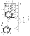
- Figure 1 is a schematic illustration of an image forming system suitable for practicing an embodiment of the image forming method according to the invention.
- Figure 2 illustrates an alternating electric field for development in the system shown in Figure 1.
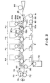
- Figure 3 illustrates a full-color image forming system.
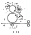
- Figures 4 and 5 are respectively a schematic illustration of an image forming apparatus suitable for practicing another embodiment of the image forming method according to the invention.
- Figure 6 illustrates an apparatus for measuring a volumetric resistivity.
- a magnetic carrier obtained by coating a carrier core of a magnetic fine powder-dispersed resin with a fluorine-containing coating resin simultaneously with or immediately after treatment with a specific coupling agent so as to provide a resistivity of 5x10 11 - 5x10 15 ohm.cm.
- the magnetic carrier of the present invention comprising magnetic fine particles dispersed in a resin has a true specific gravity of 2.5 - 4.5, preferably 3.0 - 4.3. If the true specific gravity is in this range, the toner receives only a small load during blending under stirring of the magnetic carrier and the toner, the soiling of the carrier surface with the toner is suppressed, and the carrier attachment onto a non-image part on the electrostatic image-bearing member is also suppressed.
- the magnetic carrier has magnetic properties in these ranges, the attachment of the magnetic carrier onto the electrostatic image-bearing member is suppressed and the compression force applied onto the toner in the magnetic brush of two-component developer is alleviated to suppress the soling of the carrier with the toner particles and the external additive, under the action of a magnetic field exerted by a magnetic field-generating means, such as a fixed magnet, disposed within a developer-carrying member (developing sleeve).
- a magnetic field-generating means such as a fixed magnet
- the magnetic carrier of the present invention has a resistivity in the range of 5x10 11 - 5x10 15 ohm.cm, so that the magnetic carrier is less liable to cause carrier attachment onto the electrostatic image-bearing member and better suppresses the toner charge-up.
- the magnetic carrier has a resistivity below 5x10 11 ohm.cm, a charge injection from the developer-carrying member to the electrostatic image-bearing member is liable to occur in the developing region, thus being liable to cause carrier attachment onto the electrostatic image-bearing member, disorder of electrostatic images and image defects.
- the magnetic carrier has a resistivity exceeding 5x10 15 ohm.cm, the charge generated by triboelectrification with the toner cannot be leaked therefrom and the toner charge is liable to be excessively increased, thus being liable to cause a image density lowering and fog due to the toner charge-up, particularly in low humidity environment. Further, a problem of image density lowering in a middle part of a solid image than at the peripheral edge, is liable to occur.
- the magnetic carrier of the present invention is also characterized in that
- a carrier core composed of a first resin and magnetic fine particles By surface-coating a carrier core composed of a first resin and magnetic fine particles with a second resin having at least the above-mentioned three types of units, it becomes possible to provide a magnetic carrier capable of suppressing the soiling with the toner and the external additive while retaining an ability of providing a negative triboelectric charge to a negatively chargeable toner.
- the surface coating of the carrier core with the second resin is effected, either by first treading the carrier core surface with a coupling agent having at least an amino group and a methylene unit and then coating the treated carrier core with the second resin, or by surface-coating the carrier core with a mixture of the second resin and the coupling agent, an improved adhesion is given between the carrier core and the second resin, and the resultant carrier is provided with an enhanced negative triboelectric charge-imparting ability.
- Examples of the first resin constituting the carrier core may include: vinyl resins, polyester resins, epoxy resins, phenolic resins, urea resins, polyurethane resins, polyimide resins, cellulose resins and polyether resins, each having a methylene unit (-CH 2 -) in its polymer chain. These resins may be used singly or in mixture of two or more species.
- vinyl monomer for providing the vinyl resin may include: styrene; styrene derivatives, such as o-methylstyrene, m-methylstyrene, p-methylstyrene, p-phenylstyrene, p-ethylstyrene, 2,4-dimethylstyrene, p-n-butylstyrene, p-tert-butylstyrene, p-n-hexylstyrene, p-n-octylstyrene, p-n-nonylstyrene, p-n-decylstyrene, p-n-dodecylstyrene, p-methoxystyrene, p-chlorostyrene, 3,4-dichlorostyrene, m-nitrostyrene, o-nitrostyren
- the magnetic carrier core particles comprising magnetic fine particles dispersed in the first resin may for example be prepared by subjecting a mixture of a monomer and magnetic fine particles to polymerization to directly provide carrier core particles.
- the monomer used for the polymerization may include the above-mentioned vinyl monomers, a combination of a bisphenol or a derivative thereof and epichlorohydrin for producing epoxy resins; a combination of a phenol and an aldehyde for producing phenolic resins; a combination of urea and an aldehyde for producing a urea resin; and a combination of melamine and an aldehyde.
- a carrier core including cured phenolic resin may be produced by subjecting a phenol and an aldehyde in mixture with magnetic fine particles as described above, and optionally a dispersion stabilizer, to polycondensation in the presence of a basic catalyst in an aqueous medium.
- the magnetic carrier core particles may also be produced through a process wherein starting materials including a thermoplastic resin, magnetic fine particles and other additives may be sufficiently blended by a blender, and melt-kneaded through kneading means, such as hot rollers, a kneader or an extruder, followed by cooling, pulverization and classification to obtain carrier core particles.
- the resultant resinous core particles may preferably be spherized (i.e., made spherical) thermally or mechanically to provide spherical core particles.
- the carrier may preferably have a shape factor SF-1 (as described hereinafter) of 100 - 130 so as to provide the two-component developer with improved developing performance.
- thermosetting resin such as phenolic resin, melamine resin or epoxy resin in view of excellent durability, impact resistance and heat-resistance.
- phenolic resin In order to better exhibit the characteristic performances attained by the present invention, it is further preferred to use phenolic resin.
- the magnetic fine particles and the non-magnetic inorganic compound fine particles may preferably be contained in total of 70 - 99 wt. %, more preferably 80 - 99 wt. %, of the resultant magnetic carrier, so as to provide a good combination of true specific gravity and resistivity of the carrier, and mechanical properties of the carrier core.
- non-magnetic inorganic compound fine particles have a larger resistivity and a larger number-average particle size, respectively, than those of the magnetic fine particles, so as to provide the carrier with a higher resistivity and a smaller true specific gravity.
- the magnetic fine particles are used in 30 - 95 wt. % of the total of the magnetic fine particles and the nonmagnetic inorganic compound fine particles so that the carrier receives appropriate level of magnetic force for preventing carrier attachment and has an appropriate level of resistivity.
- the carrier has a number-average particle size of 15 - 60 ⁇ m, and the magnetic fine particles have a number-average particle size (r a ) of 0.02 - 2 ⁇ m, particularly 0.05 - 1 ⁇ m.
- the nonmagnetic inorganic compound fine particles have a number-average particle size (r b ) of 0.05 - 5 ⁇ m, which is at least 1.5 times that (r a ) of the magnetic fine particles.
- the magnetic fine particles used in the present invention it is possible to use fine particles of a ferromagnetic iron oxide, such as magnetite or maghemite, and fine particles of spinel ferrites also containing at least one species of metal elements other than iron, such as Mn, Ni, Zn, Mg and Cu, fine particles of magneto-plumbite-form ferrite such as barium ferrite and fine particles of iron or iron alloys having a surface oxide film.
- Magnetite fine particles are particularly preferred.
- the magnetic fine particles may preferably have a number-average particle size of 0.02 - 3 ⁇ m, particularly 0.05 - 1 ⁇ m, in view of its dispersibility in an aqueous medium and the strength of spherical carrier core particles obtained in a preferred embodiment.
- the particle shape of the magnetic fine particles may be any of granular, spherical and acicular, while a spherical shape is preferred.
- the non-magnetic inorganic compound fine particles may preferably have a resistivity of 10 8 - 10 15 ohm.cm. It is possible to use fine particles of, e.g., titanium oxide, silica, alumina, zinc oxide, magnesium oxide, hematite, goethite or ilmenite. It is preferred to use non-magnetic fine particles not having a substantial difference in specific gravity with the magnetic fine particles, such as those of hematite, zinc oxide and titanium oxide.
- the non-magnetic inorganic compound fine particles may preferably have a number-average particle size of 0.05 - 5 ⁇ m, particularly 0.1 - 3 ⁇ m, in view of the dispersibility in an aqueous medium and the strength of the resultant carrier core particles.
- the magnetic fine particles comprise fine particles of magnetite, or fine particles of a magnetic ferrite containing at least iron and magnesium, and the non-magnetic inorganic compound fine particles comprise fine particles of hematite ( ⁇ -Fe 2 O 3 ), so as to provide the carrier with appropriate levels of magnetite properties, true specific gravity and resistivity.
- a phenol compound having a phenolic hydroxyl group examples of which may include: phenol per se; alkylphenols, such as o-cresol, m-cresol, p-tert-butylphenol, o-propylphenol, resorcinol and bisphenol A; and halogenated phenols obtained by substituting a halogen atom, such as chlorine or bromine, for one or more hydrogen atoms on the benzene nucleus or alkyl group of the phenol or alkylphenols.
- phenol i.e., hydroxybenzene
- such a phenol compound may be reacted with an aldehyde compound, such as formaldehyde (e.g., in the form of formalin or paraformaldehyde) or furfural.
- formaldehyde e.g., in the form of formalin or paraformaldehyde
- furfural e.g., in the form of formalin or paraformaldehyde
- Formaldehyde is preferred.
- the polycondensation reaction between the phenol compound and the aldehyde compound is promoted in the presence of a basic catalyst, which may be one ordinarily used for production of resol resins.
- a basic catalyst may include: ammonia water, hexamethylenetetramine, and alkylamines, such as dimethylamine, diethyltriamine and polyethyleneimine.
- Such a basic catalyst may preferably be used in a ratio of 0.02 - 0.3 mol per mol of the phenol compound.
- the second resin surface-coating the magnetic carrier core particles has at least a fluoroalkyl unit, a methylene unit and an ester unit.
- the fluoroalkyl unit effective for preventing the attachment of the toner external additive onto the carrier particle surfaces
- a perfluoroalkyl unit as represented by: wherein m is an integer of 0 - 20.
- the fluoroalkyl unit and the methylene unit are bonded to each other so as to provide a bonded unit of, e.g., wherein m is an integer of 0 - 20, and n is an integer of 1 - 15.
- the second resin has a combined unit as represented by: wherein m is an integer of 0 - 20, and n is an integer of 1 - 15.
- the second resin is a polymer or copolymer of methacrylic acid or methacrylate ester having a fluoroalkyl unit, or a polymer or copolymer of ethacrylic acid or ethacrylate ester having a fluoroalkyl unit.
- the second resin may preferably have a unit of at least one of the following two formulae: or wherein m is an integer of 0 - 20, and n is an integer of 1 - 15.
- the second resin may preferably be in the form of a graft copolymer having a fluoroalkyl unit.
- a graft copolymer may be characterized by having, in combination, a unit represented by: wherein R 1 denotes a hydrogen or alkyl group, R 2 denotes a hydrogen atom or an alkyl group of 1 - 20 carbon atoms, and k is an integer of at least 1; and a unit represented by: wherein m is an integer of 1 - 20, and n is an integer of 1 - 15.
- the graft copolymer may preferably have a structure including a main chain (or trunk polymer) comprising a (co)polymer (i.e., polymer or copolymer) having a perfluoroalkyl group, and a side chain (or branch polymer) comprising an alkyl methacrylate (co)polymer, an alkyl acrylate (co)polymer, or alkyl methacrylate-alkyl acrylate copolymer.
- a main chain or trunk polymer
- a (co)polymer i.e., polymer or copolymer having a perfluoroalkyl group
- side chain or branch polymer
- the second resin may preferably have a weight-average molecular weight (Mw) of 2x10 4 - 3x10 5 based on gel permeation chromatography (GPC) of its THF (tetrafluorofuran)-soluble content so as to provide a coating layer exhibiting sufficient strength and adhesion with the carrier core particles and good applicability.
- Mw weight-average molecular weight
- GPC gel permeation chromatography
- the second resin has a molecular weight distribution as to provide a GPC chromatogram based in its THF-soluble content exhibiting a main peak in a molecular weight region of 2x10 3 - 10 5 , and more preferably further a sub-peak or shoulder in a molecular weight region of 2x10 3 - 10 5 .
- the GPC chromatograph of the THF-soluble content of the second region exhibits a main peak in a molecular weight range of 2x10 4 - 10 5 and a sub-peak or shoulder in a molecular weight region of 2x10 3 - 1.9x10 4 .
- the magnetic carrier coated with the second resin can exhibit further improved continuous image forming performances on a large number of sheets, stability of charging toner and freeness from attachment of the toner additive onto the carrier particles.
- the second resin in the form of a graft copolymer may preferably have a weight-average molecular weight of 3x10 4 to 2x10 5 including a grafting polymer unit exhibiting a weight-average molecular weight of 3x10 3 - 1x10 4 .
- the molecular weight distribution and weight-average molecular weight of a THF-soluble content of a coating resin described herein are based on values measured by gel permeation chromatography performed according to the following conditions.
- the molecular weight levels of chromatograms are determined based on a calibration curve prepared by using mono-disperse polystyrene disperse samples.
- the second resin may have a form of a graft polymer containing 5 - 80 wt. % of a trunk polymer comprising polymerized units of an ⁇ , ⁇ -unsaturated carboxylic acid ester having a fluoroalkyl unit-containing ester group.
- the preferred content is determined based on a sufficient releasability (i.e., anti-soiling characteristic) and adhesion with the carrier core.
- the ⁇ , ⁇ -unsaturated carboxylic acid ester may preferably be an alkyl acrylate or an alkyl methacrylate.
- the alkyl group can have a hydrophilic substituent, such as a hydroxyl group.
- An alkyl methacrylate is preferred, particularly methyl methacrylate.
- the four atoms of X, X*, Y and Y* may preferably include at least three hydrogen atoms, and it is further preferred that all 4 of these atoms are hydrogen atoms.
- R may preferably be a methyl group since it tends to provide a tougher coating film than in the case of hydrogen atom.
- m is 4 to 9 because a smaller m is liable to result in a lowering in release effect owing to the fluorine atom of the coating film.
- Such a graft copolymer may be produced by reacting a macromer having a terminal ethylenically unsaturated group (providing a branch or branches) with an ethylenically unsaturated monomer (providing a trunk polymer).
- a graft copolymer may also be produced by reacting a macromer having a terminal group capable of condensation reaction in the presence of a functional group cable of condensation reaction or a chain transfer agent.
- the "macromer” means a polymer or copolymer having a weight-average molecular weight of 3000 - 10,000 and also retaining a terminal reactive ethylenically unsaturated group.
- Such a macromer may be produced by ionic polymerization or radical polymerization.
- a macromer is dissolved in an ethylenically unsaturated monomer having a perfluoroalkyl group, and the reactive ethylenically unsaturated are mutually reacted with each other to form a graft copolymer having a main chain including perfluoroalkyl group and branch(es) of the macromer unit(s).
- the macromer may be formed of polymerized units of alkyl methacrylates or alkyl acrylates, but the polymerized alkyl methacrylate units are preferred so as to provide a macromer having a higher glass transition unit.
- the coupling agent to be used for treating the magnetic carrier core particles prior to the coating with the second resin or in mixture with the second resin for coating the magnetic carrier core particles may suitably be a silane coupling agent or a titanate coupling agent.
- Preferred examples of the silane coupling agent may include: ⁇ -aminopropyltrialkoxysilane, N- ⁇ -(aminoethyl)- ⁇ -aminopropyltrialkoxysilane, N- ⁇ -(aminoethyl)- ⁇ -aminopropylmethyldialkoxysilane, and N-phenyl- ⁇ -amino-propyltrialkoxysilane.
- Preferred examples of the titanate coupling agent may include: isopropyltri(N-aminoethylaminoethyl) titanate, and isopropyl-4-aminobenzene-sulfonyl-di(dodecylbenzenesulfonyl) titanate.
- the carrier core particles include the first resin having methylene units in the polymer chain, and the carrier core particles are coated with the coupling agent having an amino group and a methylene unit, and also the second resin having a fluoroalkyl unit, a methylene unit and an ester unit.
- the coupling agent forms a polymer by reaction between molecules thereof or is reacted with the first resin or the second resin to provide an enhanced adhesion and affinity with the first and second resins.
- the amino group of he coupling agent suppresses the negative chargeability given by the fluoroalkyl group and enhances the carrier ability of imparting a negative charge to the toner.
- a preferred combination is provided by using a phenolic resin as the first resin (i.e., binder resin for the carrier core particles) and a fluoro-alkyl group-containing graft polymer as the second resin for coating the carrier core.
- a phenolic resin as the first resin (i.e., binder resin for the carrier core particles)
- a fluoro-alkyl group-containing graft polymer as the second resin for coating the carrier core.
- the magnetic carrier core particles are coated with 0.01 - 5 wt. % of the second resin and 0.01 - 5 wt. % of the coupling agent respectively based on the resultant magnetic carrier, so as to stabilize the ability of triboelectrically charging a negatively chargeable toner, improve the continuous image forming performances on a large number of sheets of the carrier and suppress the soilability with the external additive and the toner.
- the magnetic carrier of the present invention may preferably have a bulk density of at most 3.0 g/cm 3 , more preferably at most 2.0 g/cm 3 , as measured according to JIS K5101. In excess of 3.0 g/cm 3 , a large shearing force is caused within the developer whereby the carrier is liable to be soiled with spent toner or suffer from peeling of the coating resin.
- the shape of the magnetic carrier may be appropriately selected so as to suit a prescribed system where it is used. It is however generally preferred that the magnetic carrier has a sphericity or shape factor SF-1 of 100 - 130, more preferably 100 - 120. If the magnetic carrier has a sphericity exceeding 130, the resultant developer is liable to have inferior flowability, whereby the developer is caused to show a lower triboelectric charging ability to the toner and is liable to form a non-uniform shape of magnetic brush, thus failing to provide high-quality images.
- the core of the magnetic carrier may preferably comprise magnetite or ferrite showing magnetism as represented by a general formula of MO.Fe 2 O 3 or MFe 2 O 4 , wherein M denotes a divalent or monovalant metal, such as Ca, Mn, Fe, Ni, Co, Cu, Mg, Zn, Cd, or Li. M denotes a single species or plural species of metals.
- magnetite or ferrite may include: iron-based oxide materials, such as magnetite, ⁇ -iron oxide, Mn-Zn-Fe-based ferrite, Ni-Zn-Fe-based ferrite, Mn-Mg-Fe-based ferrite, Ca-Mn-Fe-based ferrite, Ca-Mg-Fe-based ferrite, Li-Fe-based ferrite, and Cu-Zn-Fe-based ferrite.
- iron-based oxide materials such as magnetite, ⁇ -iron oxide, Mn-Zn-Fe-based ferrite, Ni-Zn-Fe-based ferrite, Mn-Mg-Fe-based ferrite, Ca-Mn-Fe-based ferrite, Ca-Mg-Fe-based ferrite, Li-Fe-based ferrite, and Cu-Zn-Fe-based ferrite.
- magnetite is most preferably used also from an economical viewpoint.
- non-magnetic metal oxides including one or plural species of metals, such as Mg, Al, Si, Ca, Sc, Ti, V, Cr, Mn, Fe, Co, Ni, Cu, Zn, Sr, Y, Zr, Nb, Mo, Cd, Sn, Ba and Pb.
- specific examples of non-magnetic metal oxides may include: Al 2 O 3 , SiO 2 , CaO, TiO 2 , V 2 O 5 , CrO 2 , MnO 2 , ⁇ -Fe 2 O 3 , CoO, NiO, CuO, ZnO, SrO, Y 2 O 3 and ZrO 2 .
- the magnetic fine particles and the non-magnetic inorganic compound fine particles are co-present in a total weight which is 0.5 - 200 times that of the phenol compound.
- a total weight of 4 - 100 times is further preferred in view of the strength of the thus-produced magnetic carrier core particles.
- the magnetic fine particles and the non-magnetic inorganic compound fine particles may be used as they are without a surface treatment or may be used after a lipophilization or lipophilicity-imparting treatment.
- a suspension stabilizer e.g., a hydrophilic organic compound, such as carboxymethylcellulose or polyvinyl alcohol, or a fluorine compound, such as calcium fluoride.
- the lipophilization treatment may for example be performed by a method of blending the magnetic fine particles or non-magnetic inorganic compound fine particles with a coupling agent, such as a silane coupling agent or a titanate coupling agent added thereto for surface-coating, or a method of dispersing the magnetic fine particles or non-magnetic inorganic compound fine particles within an aqueous medium containing a surfactant to cause the fine particles adsorb the surfactant.
- the magnetic fine particles and the non-magnetic inorganic compound fine particles may be lipophilized simultaneously or separately, or only one of them may be lipophilized.
- the surfactant may be a commercially available one. It is preferred to use a surfactant having a functional group capable of bonding with hydroxyl groups present at the surface of the magnetic fine particles or the non-magnetic inorganic compound fine particles. Ionic surfactants, such as cationic surfactants and anionic surfactant may be preferred.
- a phenol compound, an aldehyde compound, water, the magnetic fine particles and the nonmagnetic inorganic compound fine particles are charged in a reaction vessel and sufficiently stirred therein. Thereafter, a basic catalyst is added and the system is warmed and held at a reaction temperature of 70 - 90 °C under stirring to form a cured phenolic resin. At this time, in order to provide spherical composite particles having a high sphericity, it is preferred that the system temperature is gradually raised at a rate of 0.5 - 1.5 °C/min., more preferably 0.8 - 1.2 °C/min.
- the reaction product after the curing is cooled to 40 °C or below, and the resultant aqueous dispersion is subjected to a conventional solid-liquid separation, such as filtration or centrifugation, followed by washing and drying to obtain spherical magnetic carrier core particles comprising the magnetic fine particles and the non-magnetic inorganic compound fine particles bound by a cured phenolic resin as the binder resin.
- a conventional solid-liquid separation such as filtration or centrifugation
- the coating of the magnetic carrier core particles may for example be performed by applying a coating liquid formed by dissolving or suspending a resin in a solvent or a liquid medium onto the magnetic carrier core particles.
- the magnetic carrier and the toner may be blended in such a ratio as to provide a toner concentration of 2 - 15 wt. %, preferably 4 - 13 wt. %, so as to provide a good result.
- the resultant image density is liable to be low and in excess of 15 wt. %, fog and toner scattering in the apparatus are liable to occur, and the life of the developer is liable to be shortened.
- the toner used for constituting the two-component developer of the present invention has a weight-average particle size a providing a ratio a/b of 0.1 - 0.3 with the number-average particle size b of the magnetic carrier. If the ratio is below 0.1, it becomes difficult to well charge the toner, and fog and toner scattering in a high humidity environment are liable to occur. On the other hand, in excess of 0.3, the toner is liable to have an excessively high charge especially in a low humidity environment, thus being liable to cause a lowering in image density and fog.
- the toner used in the present invention may preferably have a weight-average particle size (D4) of 3 - 9.9 ⁇ m, more preferably 4.5 - 8.9 ⁇ m. Further, in order to effect good triboelectrification free from occurrence of reverse charge fraction and good reproducibility of latent image dots, it is preferred to satisfy such a particle size distribution that the toner particles contain at most 20 % by number in accumulation of particles having particle sizes in the range of at most a half of the number-average particle size (D1) thereof and contain at most 10 % by volume in accumulation of particles having particle sizes in the range of at least two times the weight-average particle size (D4) thereof.
- D4 weight-average particle size
- the toner particles contain at most 15 % by number, further preferably at most 10 % by number, of particles having sizes of at most 1/2 x D1, and at most 5 % by volume, further preferably at most 2 % by volume of particles having sizes of at least 2xD4.
- the toner has a weight-average particle size (D4) exceeding 9.9 ⁇ m, the toner particles for developing electrostatic latent images become so large that development faithful to the latent images cannot be performed even if the magnetic force of the magnetic carrier is lowered, and extensive toner scattering is caused when subjected to electrostatic transfer. If D4 is below 3 ⁇ m, the toner causes difficulties in powder handling characteristic.
- the triboelectrification of such fine toner particles cannot be satisfactorily effected to result in difficulties, such as a broad triboelectric charge distribution of the toner, charging failure (occurrence of reverse charge fraction) and a particle size change during continuous image formation due to localization of toner particle sizes.
- the cumulative amount of particles having sizes of at least two times the weight-average particle size (D4) exceeds 10 % by volume, the triboelectrification with the magnetic carrier becomes difficult, and faithful reproduction of latent images becomes difficult.
- the toner particle size distribution may be measured, e.g., by using a Coulter counter.
- the binder resin for the toner used in the present invention may for example comprise: homopolymers of styrene and derivatives thereof, such as polystyrene, poly-p-chlorostyrene and polyvinyltoluene; styrene copolymers such as styrene-p-chlorostyrene copolymer, styrene-vinyltoluene copolymer, styrene-vinylnaphthalene copolymer, styrene-acrylate copolymer, styrene-methacrylate copolymer, styrene-methyl-a-chloromethacrylate copolymer, styrene-acrylonitrile copolymer, styrene-vinyl methyl ether copolymer, styrene-vinyl ethyl ether copolymer, styrene-viny
- Examples of the comonomer constituting such a styrene copolymer together with styrene monomer may include other vinyl monomers inclusive of: monocarboxylic acids having a double bond and derivative thereof, such as acrylic acid, methyl acrylate, ethyl acrylate, butyl acrylate, dodecyl acrylate, octyl acrylate, 2-ethylhexyl acrylate, phenyl acrylate, methacrylic acid, methyl methacrylate, ethyl methacrylate, butyl methacrylate, octyl methacrylate, acrylonitrile, methacrylonitrile, and acrylamide; dicarboxylic acids having a double bond and derivatives thereof, such as maleic acid, butyl maleate, methyl maleate and dimethyl maleate; vinyl esters, such as vinyl chloride, vinyl acetate, and vinyl benzoate; ethylenic olefin
- the toner used in the present invention may preferably contain a THF-soluble portion of the binder resin exhibiting a number-average molecular weight of 3x10 3 - 10 6 , more preferably 6x10 3 - 2x10 5 .
- binder resin inclusive of styrene polymers or copolymers has been crosslinked or can assume a mixture of crosslinked and un-crosslinked polymers.
- the crosslinking agent may principally be a compound having two or more double bonds susceptible of polymerization, examples of which may include: aromatic divinyl compounds, such as divinylbenzene, and divinylnaphthalene; carboxylic acid esters having two double bonds, such as ethylene glycol diacrylate, ethylene glycol dimethacrylate and 1,3-butanediol dimethacrylate; divinyl compounds, such as divinylaniline, divinyl ether, divinyl sulfide and divinylsulfone; and compounds having three or more vinyl groups. These may be used singly or in mixture.
- aromatic divinyl compounds such as divinylbenzene, and divinylnaphthalene
- carboxylic acid esters having two double bonds such as ethylene glycol diacrylate, ethylene glycol dimethacrylate and 1,3-butanediol dimethacrylate
- divinyl compounds such as divinylaniline, divinyl ether, divinyl s
- Such a crosslinking agent may preferably be added in 0.001 - 10 wt. parts per 100 wt. parts of the polymerizate monomer.
- the toner can contain a charge control agent.
- an organic metal compound or chelate compound may effectively be used for example.
- Preferred examples may include: monoazo metal compounds, acetylacetone metal compounds, and metal compounds of aromatic hydroxycarboxylic acids and aromatic dicarboxylic acids.
- aromatic hydroxycarboxylic acids aromatic mono- and polycarboxylic acids, and metal salts, esters, and phenol derivatives with bisphenols, etc., of these acids; urea derivatives, metal-containing salicylic acid compounds; metal-containing naphthoic acid compounds; boron compound; quaternary ammonium salts: calixarenes; silicon compounds; styrene-acrylic acid copolymer; styrene-methacrylic acid copolymer; styrene-acryl-sulfonic acid copolymer; and non-metal carboxylic acid compounds.
- Metal compounds of aromatic hydroxycarboxylic acids are particularly preferred because they are colorless or only slightly colored.
- Such a charge control agent may be used in 0.01 - 20 wt. parts, preferably 0.1 - 10 wt. parts, more preferably 0.2 - 4 wt. parts, per 100 wt. parts of the toner binder resin.
- the colorant used in the present invention may include a black colorant, yellow colorant, a magenta colorant and a cyan colorant.
- a black colorant it is possible to use a magnetic material.
- non-magnetic black colorant may include: carbon black, and a colorant showing black by color-mixing of yellow/magenta/cyan colorants as shown below.
- yellow colorant may include: condensed azo compounds, isoindolinone compounds, anthraquinone compounds, azo metal complexes, methin compounds and arylamide compounds. Specific preferred examples thereof may include C.I. Pigment Yellow 12, 13, 14, 15, 17, 62, 74, 83, 93, 94, 95, 109, 110, 111, 128, 129, 147, 168 and 180.
- magenta colorant may include: condensed azo compounds, diketopyrrolpyrrole compounds, anthraquinone compounds, quinacridone compounds, basis dye lake compounds, naphthol compounds, benzimidazole compounds, thioindigo compounds an perylene compounds. Specific preferred examples thereof may include: C.I. Pigment Red 2, 3, 5, 6, 7, 23, 48:2, 48:3, 48:4, 57:1, 81:1, 144, 146, 166, 169, 177, 184, 185, 202, 206, 220, 221 and 254.
- cyan colorant may include: copper phthalocyanine compounds and their derivatives, anthraquinone compounds and basis dye lake compounds. Specific preferred examples thereof may include: C.I. Pigment Blue 1, 7, 15, 15:1, 15:2, 15:3, 15:4, 60, 62, and 66.
- colorants may be used singly, in mixture of two or more species or in a state of solid solution.
- the above colorants may be appropriately selected in view of hue, color saturation, color value, weather resistance, transparency of the resultant OHP film, and a dispersibility in toner particles.
- the above colorants may preferably be used in a proportion of 1 - 20 wt. parts per 100 wt. parts of the binder resin.
- a black colorant comprising a magnetic material may preferably be used in a proportion of 40 - 150 wt. parts per 100 wt. parts of the binder resin.
- the toner particles may contain a wax as desired. It is preferred to use a wax having a ratio (Mw/Mn) between weight-average molecular weight (Mw) and number-average molecular weight (Mn) of at most 1.45 and a solubility parameter of 8.4 - 10.5, so as to provide a toner showing an excellent fluidity capable of providing uniform fixed images free of gloss irregularity and less liable to soil the fixing member of the fixing apparatus or cause lowering in storage stability. Further, the toner thus obtained can exhibit good fixability to provide fixed images showing good light transmittance. When the toner is melted to form full-color images, the wax can partially or wholly coat the heating member to suppress the toner offsetting, thereby providing a satisfactory full-color OHP film. The toner also can show a good low-temperature fixability and allow the long life of the pressing member.
- the wax contained in the toner may preferably have an Mw/Mn ratio of at most 1.45, more preferably at most 1.30, based on a molecular weight distribution as measured according to gel permeation chromatography (GPC), so as to provide uniform fixed images and good transferability of the toner, and suppress the soiling of a contact charging means for contact-charging the photosensitive member.
- GPC gel permeation chromatography
- the toner is liable to have inferior fluidity, thus resulting in gloss irregularity of the fixed images, and is further liable to have a lower transferability and soil the contact charging member.
- Mw/Mn of waxes described herein are based on molecular weight distributions measured by GPC under the following conditions.
- the molecular weight distribution of a sample is obtained once based on a calibration curve prepared by monodisperse polystyrene standard samples, and recalculated into a distribution corresponding to that of polyethylene using a conversion formula based on the Mark-Houwink viscosity formula.
- the wax used in the present invention may preferably have a melting point of 30 - 150 °C, more preferably 50 - 120 °C. If the melting point of the wax is below 30 °C, the resultant toner is liable to have lower anti-blocking property and exhibit lower effects of suppressing the soiling of the developing sleeve and photosensitive member during continuous image formation on a large number of sheets. If the wax melting point exceeds 150 °C, an excessively large energy is required in the case of toner production through the pulverization process, and in the case of toner production through the polymerization process, the uniform dispersion of the wax in the binder resin requires a larger apparatus because of an increased viscosity, and the inclusion of a large amount of wax becomes difficult.
- the wax melting point described herein refers to a peaktop temperature of a main peak on a heat-absorption curve measured according to ASTM D3418-8.
- the measurement according to ASTM D3418-8 may be performed by using a differential scanning calorimeter (e.g., "DSC-7", mfd. by Perkin-Elmer Corp.).
- the detector temperature correction may be performed based on the melting points of indium and zinc, and the calorie correction may be performed based on a heat of fusion of indium.
- a sample is placed on an aluminum pan and is set in combination with a blank pan for control. The measurement is performed in a temperature range of 20 - 200 °C at a temperature-raising rate of 10 °C/min.
- the wax used in the present invention may preferably have a melt-viscosity at 100 °C of 1 - 30 mPa.sec, more preferably 3 - 30 mPa.sec.
- the wax melt-viscosity is below 1 mPa.sec, the resultant toner is liable to be damage by a shearing force acting between the toner and the carrier in the two-component developer system, and the embedding of the external additive at the toner particle surface and the toner breakage are liable to occur. If the wax melt-viscosity exceeds 50 mPa.sec, the disperse phase during toner production through the polymerization process is caused to have a high viscosity, so that it becomes difficult to obtain a small particle size toner of uniform particle sizes, thus being liable to result in a toner having a broad particle size distribution.
- the wax melt-viscosity measurement may be performed by using a rotary viscometer (e.g., "TV-500” equipped with a conical plate-shaped rotor ("PK-1", available from HAAKE Co.).
- a rotary viscometer e.g., "TV-500” equipped with a conical plate-shaped rotor ("PK-1", available from HAAKE Co.).
- PK-1 conical plate-shaped rotor
- the wax used in the present invention has such a molecular weight distribution as measured by GPC providing a chromatogram showing at least two peaks or a combination of at least one peak and at least one shoulder and exhibiting a weight-average molecular weight (Mw) of 200 - 2000, and a number-average molecular weight of 150 - 2000.
- Mw weight-average molecular weight
- the above-mentioned molecular weight distribution may be provided by a single wax species or a plurality of wax species.
- the crystallinity of the wax is inhibited to provide a toner with a better transparency.
- Two or more wax species may be blended may be performed according to any methods, e.g., melt-blending at a temperature above the melting points by means of a media disperser, such as a ball mill, a sand mill, an attritor, an apex mill, a coball mill, or a handy mill; or dissolving such waxes in a polymerizable monomer, followed by blending by means of a media disperser.
- a media disperser such as a ball mill, a sand mill, an attritor, an apex mill, a coball mill, or a handy mill
- additives such as a pigment, a charge control agent, and a polymerization initiator.
- a wax having Mw below 200 or Mn below 150 results in a toner exhibiting poor anti-blocking property.
- a wax having Mw or Mn exceeding 2000 develops crystallinity to result in a toner having a lower transparency. It is further preferred that the wax has Mw of 200 - 1500, particularly 300 - 1000, and Mn of 200 - 1500, particularly 250 - 1000.
- Such a wax may be added in 1 - 40 wt. parts, preferably 2 - 30 wt. parts, per 100 wt. parts of the toner binder resin.
- the wax may preferably be added in 1 - 10 wt. parts, more preferably 2 - 7 wt. parts, per 100 wt. parts of the binder resin.
- the wax may preferably be added in 2 - 40 wt. parts, more preferably 5 - 30 wt. parts, further preferably 10 - 20 wt. parts.
- the wax can be incorporated in a larger amount in the toner particles since a wax having a lower polarity than the binder resin can be easily enclosed within toner particles in an aqueous polymerization system. This is advantageous for providing a better anti-offset effect in the fixation step.
- the wax amount is too low the anti-offset effect is liable to be inferior. If the wax amount is excessively large, the resultant toner is liable to cause melt-sticking onto the photosensitive drum and the developing sleeve distribution is liable to be formed.
- the waxes suitably used in the present invention may include, e.g., paraffin wax, polyolefin wax, products obtained by modification (such as oxidation and grafting) of these waxes, higher fatty acids and metal salts thereof, amide waxes, and ester waxes.
- ester waxes are particularly preferred as they propiole full-color OHP image is higher qualities.
- ester waxes preferably used in the present invention may for example be produced through processes including oxidation, synthesis from carboxylic acids and derivatives thereof, and ester group-introduction reactions as represented by Michael addition reaction.
- the ester waxes may particularly preferably be formed through a dehydrocondensation reaction of a carboxylic acid and an alcohol compound as represented by formula (1) below, or a reaction between an oxyhalide and an alcohol compound as represented by formula (2) below: nR 1 -COOH + R 2 (OH) n ⁇ R 2 (OCO-R 1 ) n + nH 2 O nR 1 -COCl + R 2 (OH) n ⁇ R 2 (OCO-R 1 ) n + nNCl wherein R 1 and R 2 independently denote an organic group, such as an alkyl group, an alkenyl group, an aralkyl or an aromatic group, and n is an integer of 1 - 4.
- the organic group may include 1 - 50 carbon atoms, preferably 2 - 45 carbon atoms, further preferably 4 - 30 carbon atoms.
- the organic group may preferably be linear one.
- an excessive amount of the alcohol may be used or the reaction may be performed in an aromatic organic solvent capable of forming an azeotropic mixture with water while using a Dean - Stark water separator.
- an acid halide it is possible to use a system of aromatic organic solvent containing a base added thereto for accepting the by-produced acid to promote the ester formation reaction.
- the toner used in the present invention may be produced through the pulverization process or a special toner production process as represented by the polymerization process.
- a binder resin, a wax, a colorant, such as a pigment, dye or magnetic material, and optionally, a charge control agent and other additives are sufficiently blended by a blended, such as a Henschel mixer or a ball mill; the thus-obtained blend is melt-kneaded by a hot-kneading means, such as hot rollers, a kneader or an extruder, to disperse or dissolve the colorant and other additives in the mutually melted resin components; and the resultant kneaded product is cooled to be solidified, pulverized and classified to provide toner particles.
- a blended such as a Henschel mixer or a ball mill
- the resultant toner particles may be blended, as desired, with prescribed additives (i.e., external additive) to obtain a toner used in the present invention.
- prescribed additives i.e., external additive
- spherical toner particles For production of spherical toner particles, it is possible to adopt a process of spraying a molten mixture into air by using a disk or a multi-fluid nozzle as disclosed in JP-B 56-13945, etc.; a process for directly producing toner particles according to suspension polymerization as disclosed in JP-B 36-10231, JP-A 59-53856, and JP-A 59-61842; a dispersion polymerization process for directly producing toner particles in an aqueous organic solvent in which the monomer is soluble but the resultant polymer is insoluble; a process for producing toner particles according to emulsion polymerization as represented by soap-free polymerization wherein toner particles are directly formed by polymerization in the presence of a water-soluble polymerization initiator; and a hetero-aggregation process wherein primary polar emulsion polymerizate particles and then polar particles of the opposite polarity are added to cause aggregation.
- the dispersion polymerization process provides toner particles having an extremely sharp particle size distribution but allows only a narrow latitude for selection of usable materials, and the use of an organic solvent requires a complicated production apparatus and troublesome operations accompanying the disposal of a waste solvent and inflammability of the solvent. Accordingly, it is preferred to adopt a process wherein a composition comprising at least a polymerizable monomer, a colorant and a wax is polymerized in an aqueous medium to directly produced toner particles.
- the emulsion polymerization process as represented by the soap-free polymerization is effective for providing toner particles having a relatively narrow particle size distribution, but the used emulsifier and polymerization initiator terminal are liable to be present at the toner particle surfaces, thus resulting in an inferior environmental characteristic.
- the suspension polymerization process under the normal or elevated pressure, capable of relatively easily providing toner particles having a sharp particle size distribution. It is also possible to adopt a seed polymerization process wherein a monomer is further adsorbed onto once-obtained polymerizate particles and polymerized by using a polymerization initiator.
- the toner particles used in the present invention may preferably have a microtexture comprising a wax enclosed within an outer shell resin as confirmed by a sectional view observed through a transmission electron microscope (TEM).
- TEM transmission electron microscope
- the wax cannot be dispersed uniformly to result in a toner having a broad particle size distribution and liable to cause melt-sticking onto the apparatus members.
- a composition containing a wax having a smaller polarity than a principal monomer constituting the composition may be dispersed in an aqueous medium, and a small amount of a resin or monomer having a larger polarity is also included in the composition to form an outer shell, thus providing toner particles having a so-called core/shell structure.
- toner particles may be observed in the following manner. Sample toner particles are sufficiently dispersed in a cold-setting epoxy resin, which is then hardened for 2 days at 40 °C. The hardened product is dyed with triruthenium tetroxide optionally together with triosmium tetroxide and sliced into thin flakes by a microtome having a diamond cutter. The resultant thin flake sample is observed through a transmission electron microscope to confirm a sectional structure of toner particles.
- the dyeing with triruthenium tetroxide may preferably be used in order to provide a contrast between the wax and the outer resin by utilizing a difference in crystallinity therebetween.
- the toner particle production through a direct polymerization process may be performed in the following manner.
- a wax, a colorant, a charge control agent, a polymerization initiator, and other optional additives may be added, and the mixture is uniformly dissolved or dispersed by a homogenizer, an ultrasonic disperser, etc., to form a polymerizable monomer composition, which is then dispersed in an aqueous medium containing a dispersion stabilizer by means of an ordinary stirrer, a homomixer, a homogenizer, a clear mixer, etc.
- the stirring speed and time may be adjusted so that the monomer composition will form droplets or particles having sizes identical to the objective toner particles sizes.
- the polymerization temperature may be set to 40 °C or higher, generally 50 - 90 °C.
- the temperature may be increased at a later stage of the polymerization. It is also possible to distill off a portion of the aqueous medium at a later stage of or after the polymerization, in order to remove the unreacted portion of the monomer or by-products which are liable to provide odor.
- the produced toner particles (polymerizate particles) are washed, recovered by filtration and dried. In the suspension polymerization process, it is ordinarily preferred to use 300 to 3000 wt. parts of water as a dispersion medium per 100 wt. parts of the monomer composition.
- Examples of polymerizable monomers constituting a polymerizable monomer composition for directly providing toner particles by the polymerization process may include: styrene monomers, such as styrene, o-, m- or p-methylstyrene, and m- or p-ethylstyrene; (meth)acrylate ester monomers, such as methyl (meth)acrylate, ethyl (meth)acrylate, propyl (meth)acrylate, butyl (meth)acrylate, octyl (meth)acrylate, dodecyl (meth)acrylate, stearyl (meth)acrylate, behanyl (meth)acrylate, 2-ethylhexyl (meth)acrylate, methylaminoethyl (meth)acrylate, and diethylaminoethyl (meth)acrylate; butadiene, isoprene, cyclohe
- Examples of the polar resin included in the polymerizable monomer composition may include: polymers of nitrogen-containing monomers, such as dimethylaminoethyl methacrylate and diethylaminoethyl methacrylate, and copolymers of such nitrogen-containing monomers with styrene and/or unsaturated carboxylic acid esters; polymers or copolymers with styrene monomers of nitrile monomers such as acrylonitrile, halogen-containing monomers such as vinyl chloride, unsaturated carboxylic acids such as acrylic acid and methacrylic acid unsaturated dibasic acids and anhydrides thereof, and nitro monomers; polyesters; and epoxy resins.
- Preferred examples may include: styrene-(meth)acrylic acid copolymer, maleic acid copolymer, saturated polyester resins, and epoxy resins.
- examples of the polymerization initiator may include: azo- or diazo-type polymerization initiators, such as 2,2'-azobis-(2,4-dimethylvaleronitrile), 2,2'-azobisisobutylonitrile, 1,1'-azobis(cyclohexane-2-carbonitrile), 2,2'-azobis-4-methoxy-2,4-dimethylvaleronitrile, azobisisobutyronitrile; and peroxide-type polymerization initiators such as benzoyl peroxide, methyl ethyl ketone peroxide, diisopropyl peroxycarbonate, cumene hydroperoxide, t-butyl hydroperoxide, dicumyl peroxide, 2,4-dichlorobenzoyl peroxide, lauroyl peroxide, 2,2-bis(4,4-t-butylperoxycyclohexyl)propane, and tris(t-butyl)
- a crosslinking agent In order to control the molecular weight of the resultant binder resin, it is also possible to add a crosslinking agent, a chain transfer agent, etc., in an amount of 0.001 - 15 wt. parts per 100 wt. parts of the polymerizable monomer.
- an inorganic or/and an organic dispersion stabilizer in an aqueous dispersion medium.
- the inorganic dispersion stabilizer may include: tricalcium phosphate, magnesium phosphate, aluminum phosphate, zinc phosphate, calcium carbonate, magnesium carbonate, calcium hydroxide, magnesium hydroxide, aluminum hydroxide, calcium metasilicate, calcium sulfate, barium sulfate, bentonite, silica, and alumina.
- organic dispersion stabilizer may include: polyvinyl alcohol, gelatin, methyl cellulose, methyl hydroxypropyl cellulose, ethyl cellulose, carboxymethyl cellulose sodium salt, polyacrylic acid and its salt, starch, polyacrylamide, polyethylene oxide, poly(hydroxystearic acid-g-methyl methacrylate-eu-methacrylic acid) copolymer, and nonionic and ionic surfactants.
- anionic surfactants In the emulsion polymerization process or hetero-aggregation process, anionic surfactants, cationic surfactants, ampoteric surfactants or nonionic surfactants may be used.
- dispersion stabilizers may preferably be used in the aqueous dispersion medium in an amount of 0.2 - 30 wt. parts per 100 wt. parts of the polymerizable monomer mixture.
- an inorganic dispersion stabilizer In the case of using an inorganic dispersion stabilizer, a commercially available product can be used as it is, but it is also possible to form the stabilizer in situ in the dispersion medium so as to obtain fine particles thereof.
- a surfactant in combination, thereby promoting the prescribed function of the stabilizer.
- the surfactant may include: sodium dodecylbenzenesulfonate, sodium tetradecyl sulfate, sodium pentadecyl sulfate, sodium octyl sulfate, sodium oleate, sodium laurate, potassium stearate, and calcium oleate.
- a colorant in a polymerizable monomer composition for directly providing toner particles by the polymerization process, it is necessary to pay attention to the polymerization-inhibiting function and transferability to the aqueous phase of the colorant, so that it is preferred to subject the colorant to surface modification, e.g., hydrophobization free from polymerization inhibition.
- dyes and carbon black can have polymerization dyes and carbon black can have polymerization inhibition function in many cases.
- a polymerizable monomer may be polymerized in advance in the presence of such a dye, and the resultant colored polymer may be added to the monomer composition.
- carbon black may also be treated in the above-described manner for the dyes or may also be treated with a substance reactive with a surface functional group of the carbon black, such as polyorganosiloxane.
- the wax in the toner has a melting point which is higher than the glass transition temperature of the toner binder resin by at most 100 °C, preferably at most 75 °C, further preferably at most 50 °C.
- the temperature difference exceeds 100 °C, the low-temperature fixability of the resultant toner may be impaired. If the temperature difference is too small, a good combination of toner storability and anti-high-temperature offset property can be provided for only a narrow range, so that the temperature difference may preferably be at least 2 °C.
- the glass transition temperature of the binder resin may preferably be 40 - 90 °C, more preferably 50 - 85 °C.
- the resultant toner is provided with only a low storage stability and inferior flowability, thus failing to provide good images. If the glass transition temperature of the binder resin exceeds 90 °C, the resultant toner is liable to have inferior low-temperature fixability and provide a full-color transparency with poor optical transparency, as represented by projection images with sombre halftone images and poor saturation.
- the values of glass transition temperatures described herein are based on values determined on a heat-absorption curve measured according to ASTM D3418-8.
- the measurement according to ASTM D3418-8 may be performed by using a differential scanning calorimeter (e.g., "DSC-7", mfd. by Perkin-Elmer Corp.).
- the detector temperature correction may be performed based on the melting points of indium and zinc, and the calorie correction may be performed based on a heat of fusion of indium.
- a sample is placed on an aluminum pan and is set in combination with a blank pan for control. The measurement is performed in a temperature range of 20 - 200 °C at a temperature-raising rate of 10 °C/min.
- the toner used in the present invention may suitably include, as external additives: fine particles of inorganic substances, such as silica, alumina and titanium oxide; and fine particles of organic substances, such as polytetrafluoroethylene, polyvinylidene fluoride, polymethyl methacrylate, polystyrene and silicone resins.
- fine particles of inorganic substances such as silica, alumina and titanium oxide
- organic substances such as polytetrafluoroethylene, polyvinylidene fluoride, polymethyl methacrylate, polystyrene and silicone resins.
- These external additive fine particles may preferably have a specific surface area as measured by nitrogen adsorption according to the BET method (S BET ) of at least 30 m 2 /g, particularly 50 - 400 m 2 /g, and may suitably be added in 0.1 - 20 wt. parts per 100 wt. parts of the toner particles.
- S BET BET method
- silica has a higher negative chargeability than other flowability-improving agents, such as alumina and titanium oxide, so that it exhibits a higher attachment force onto the toner particles, thus leaving less isolated external additive particles. Accordingly, it can better suppress the filming on the electrostatic image-bearing member and the soiling on the charging member. If the negative chargeability is enhanced, a portion of the external additive isolated from the toner particles is liable to be transferred onto the carrier. Even in such as case, however, the fluorine-containing resin coated carrier of the present invention can better suppress the attachment of the flowability-improving agent because of its low surface energy.
- the silica is hydrophobized in order to have a high chargeability in a high humidity environment.
- a preferred class of hydrophobization agents may include silicone oil, preferably represented by the following formula: wherein R 1 - R 10 independently denote hydrogen, hydroxyl, alkyl, halogen, phenyl, phenyl having a substituent, aliphatic group, polyoxyalkylene or perfluoroalkyl; and m and n are integers.
- a preferred class of silicone oil may have a viscosity at 25 °C of 5 - 2000 mm 2 /sec. Silicone oil having a lower viscosity because of too low a molecular weight can generate a volatile matter during a heat treatment. On the other hand, silicone oil having a higher viscosity because of too high a molecular weight makes difficult a surface treatment therewith.
- Preferred examples of silicone oil may include: methylsilicone oil, dimethylsilicone oil, phenylmethylsilicone oil, chlorophenylmethylsilicone oil, alkyl-modified silicone oil, aliphatic acid-modified silicone oil, and polyoxyalkyl-modified silicone oil.
- the silicone oil may preferably be negatively chargeable similarly as the toner particles so as to provide a toner with an enhanced chargeability.
- Inorganic fine powder may be treated with silicone oil in a known manner.
- inorganic fine powder and silicone oil may be blended directly in a blender, such as a Henschel mixer; or silicone oil may be sprayed onto inorganic fine powder. It is also possible to dissolve or disperse silicone oil in an appropriate solvent and mixing inorganic fine powder therein, followed by removing the solvent.
- Silicone oil may suitably be used in 1.5 - 60 wt. parts, preferably 3.5 - 40 wt. parts, per 100 wt. parts of the inorganic fine powder to be treated therewith.
- the surface treatment with the silicone oil can be performed uniformly to well prevent the filming and hollow image dropout, prevent the lowering in toner chargeability due to moisture absorption in a high humidity environment and prevent the lowering in image density during continuous image formation.
- image defects such as fixation toner scattering. It becomes possible to prevent the lowering in toner flowability and occurrence of fog.
- silane coupling agent may be used in 1 - 40 wt. parts, preferably 2 - 35 wt. parts per 100 wt. parts of the inorganic fine powder to be treated therewith, so as to provide improved moisture-resistance while preventing the occurrence of the agglomerate.
- a suitable class of silane coupling agents used in the present invention may include those represented the following formula: R m SiY n , wherein R denotes alkoxy or chlorine, m is an integer of 1 - 3; Y denotes a hydrocarbon group, such as alkyl vinyl, glycidoxy or methacryl; and n is an integer of 1 - 3.
- silane coupling agents may include: dimethyldichlorosilane, trimethylchlorosilane, allyldimethylchlorosilane, hexamethyldisilazane, allylphenylichlorosilane, benzyldimethylchlorosilane, vinyltriethoxysilane, ⁇ -methacryloxypropyltrimethoxysilane, vinyltriacetoxysilane, divinylchlorosilane, and dimethylvinylchlorosilane.
- the treatment of inorganic fine powder with a silane coupling agent may be performed in known manners, e.g., a dry treatment process wherein a vaporized silane coupling agent is caused to react onto inorganic fine powder in a cloud state under stirring, or a silane coupling agent is added dropwise into a dispersion of inorganic fine powder in a solvent.
- a dry treatment process wherein a vaporized silane coupling agent is caused to react onto inorganic fine powder in a cloud state under stirring, or a silane coupling agent is added dropwise into a dispersion of inorganic fine powder in a solvent.
- additives added into or added as external additives to toner particles may preferably have an average particle size which is at most 1/5 of that of the toner particles in view of continuous image forming performance of the resultant toner.
- the average particle sizes of the additives referred to herein are based on values determined electron microscopic photographs thereof (e.g., in a state of being mixed with toner particles in the case of external additives). Examples of such additives for improving toner performances may include the following.
- Flowability improvers inclusive of: metal oxides, such as silicon oxide, aluminum oxide, and titanium oxide; carbon black; and fluorinated carbon. These may preferably be hydrophobized before use.
- Abrasives inclusive of: strontium titanate, cerium oxide, aluminum oxide, magnesium oxide, and chromium oxide; nitrides, such as silicon nitride; carbides, such as silicon nitride; carbides, such as silicon carbide; and metal salts, such as calcium sulfate, barium sulfate and calcium carbonate.
- Lubricants inclusive of: power of fluorine-containing resins, such as polyvinylidene fluoride and polytetrafluoroethylene; and fatty acid metal salts, such as zinc stearate and calcium stearate.
- Charge-controlling particles inclusive of particles of metal oxides, such as tin oxide, titanium oxide, zinc oxide, silicon oxide and aluminum oxide and carbon black.
- additives may preferably be added in 0.1 - 1 wt. parts, more preferably 0.1 - 5 wt. parts, per 100 wt. parts of toner particles. These additives may be used singly or in combination of plural species.
- the negatively chargeable toner used in the present invention may preferably have a triboelectric chargeability of -15 to -40 mC/kg, more preferably -20 to -35 mC/kg, when blended with the magnetic carrier of the present invention.
- the negatively chargeable toner has a sphericity or shape factor SF-1 of 100 - 140 and is blended with at least hydrophobized silica fine powder as an external additive, so as to provide an improved developing performance.
- the two-component developer including the magnetic carrier of the present invention may for example be used for development in a system as shown in Figure 1, wherein development is performed under application of an alternating electric field and while a magnetic brush of the developer contacts an electrostatic image-bearing member, e.g., a photosensitive drum 1.
- a developer-carrying member (developing sleeve) 11 may preferably be disposed with a spacing of 100 - 1000 ⁇ m from the photosensitive drum 1 so as to well prevent the carrier attachment and provide an improved dot reproducibility. Below 100 ⁇ m, the developer supply is liable to be insufficient to result in a lower image density.
- the alternating electric field may preferably have a peak-to-peak voltage of 300 - 5000 volts, preferably 300 - 3000 volts and a frequency of 500 - 10000 Hz, more preferably 1000 - 7000 Hz, as suitably determined depending on the process.
- the alternating electric field may have an appropriate waveform, selected from various waveforms, such as triangular wave, rectangular wave, sinusoidal wave, waveforms obtained by modifying the duty ratio and intermittent alternating superposed electric field. If the application voltage is below 500 volts it may be difficult to obtain a sufficient image density and fog toner on a non-image region cannot be satisfactorily recovered in some cases. Above 5000 volts, the latent image can be disturbed by the magnetic brush to cause lower image qualities in some cases.
- Vback fog-removing voltage
- a lower primary charge voltage on the photosensitive member By using a two-component type developer containing a well-charged toner, it becomes possible to use a lower fog-removing voltage (Vback) and a lower primary charge voltage on the photosensitive member, thereby increasing the life of the photosensitive member.
- Vback may preferably be at most 200 volts, more preferably at most 150 volts.
- contrast potential 100 - 400 volts so as to provide a sufficient image density.
- the frequency can affect the process, and a frequency below 500 Hz may result in charge injection to the carrier, which leads to lower image qualities due to carrier attachment and latent image disturbance, in some cases. Above 10000 Hz, it is difficult for the toner to follow the electric field, thus being liable to cause lower image qualities.
- a contact width (developing nip) of the magnetic brush on the developing sleeve 11 with the photosensitive drum 1 at 3 - 8 mm in order to effect a development providing a sufficient image density and excellent dot reproducibility without causing carrier attachment.
- the developing nip is narrower than 3 mm, it may be difficult to satisfy a sufficient image density and a good dot reproducibility.
- the developer is apt to be packed to stop the movement of the apparatus, and it may become difficult to sufficiently prevent the carrier attachment.
- the developing nip may be appropriately adjusted by changing a distance between a developer regulating member 15 and the developing sleeve 11 and/or changing the gap between the developing sleeve 11 and the photosensitive drum 1.
- a full color image for which a halftone reproducibility is a great concern may be performed by using at least 3 developing devices for magenta, cyan and yellow, adopting the developers according to the present invention and preferably adopting a developing system for developing digital latent images in combination, whereby a development faithful to a dot latent image becomes possible while avoiding an adverse effect of the magnetic brush and disturbance of the latent image.
- the use of a toner having a narrow particle size distribution with less fine powder fraction is effective in realizing a high transfer ratio in a subsequent transfer step. As a result, it becomes possible to obtain high image qualities both at the halftone portion and the solid image portion.
- the use of the two-component developer according to the present invention is effective in reducing the shearing force applied onto the developer and also in avoiding the lowering in image quality in a continuous image formation on a large number of sheets.
- a magnetic brush charger 30 formed of magnetic particles 23 is formed on the surface of a conveyer sleeve 22 and is caused to contact the surface of an electrostatic image-bearing member (photosensitive drum) 1 to charge the photosensitive drum 1.
- the conveyer sleeve 22 is supplied with a charging bias voltage from a bias voltage application means (not shown).
- the charged photosensitive drum 1 is illuminated with laser light 24 from an exposure means (not shown) to form a digital electrostatic image thereon, which is then developed with a toner 19a contained in a two-component developer 19 according to the present invention carried on a developing sleeve 11 enclosing a magnet roller 12 therein and supplied with a developing bias voltage from a bias voltage source (not shown).
- a developing device 4 supplying the developer 19 is divided into a developer chamber R 1 and a stirring chamber R 2 by a partitioning wall 17, in which developer conveyer screws 13 and 14 are installed respectively.
- a toner storage chamber R 3 containing a replenishing toner 18, and at the bottom of the toner storage chamber R 3 is provided a toner replenishing port 20.
- the screw 13 is rotated to stir and convey the developer in the chamber R 1 in one direction along the length of the developing sleeve 11.
- the partitioning wall 17 is provided with openings (not shown) at a near side and a farther side as viewed in the drawing.
- the developer conveyed to one side of the developer chamber R 1 by the screw 31 is fed through the opening at the one side into the stirring chamber R 2 and now driven by the developer conveyer screw 14.
- the screw 14 is rotated in a direction reverse to that of the screw 13 to stir and mix the developer in the stirring chamber R 2 , the developer conveyed from the developer chamber R 1 and a fresh toner replenished from the toner storage chamber R 3 , and convey the mixture in a direction reverse to that by the screw 13 to supply the mixture into the developer chamber R 1 through the other opening of the partitioning wall 17.
- the developer 19 in the developer chamber R 1 is drawn up by a magnetic force exerted by the magnet roller 12 to be carried on the surface of the developing sleeve 11.
- the developer carried on the developer sleeve 11 is conveyed to a regulating blade 15 along with the rotation of the developing sleeve 11 to be regulated into a thin developer layer having an appropriate layer thickness and reach a developing region where the developing sleeve 11 and the photosensitive drum 1 are disposed opposite to each other.
- a magnet pole (developing pole) N 1 At a part of the magnet roller 12 corresponding to the developing region is disposed a magnet pole (developing pole) N 1 .
- the developing pole N 1 forms a developing magnetic field in the developing region, and ears of the developer are formed by the developing magnetic field to provide a magnetic brush of the developer in the developing region.
- the magnetic brush is caused to contact the photosensitive drum 1, whereby the toner in the magnetic brush and the toner on the developing sleeve 11 are transferred onto a region of electrostatic image on the photosensitive drum 1 to develop the electrostatic image, thereby providing a toner image 19a on the photosensitive drum 1.
- a portion of the developer having passed the developing region is returned into the developing device 4 where the developer is peeled off the developing sleeve 11 by a repulsive magnetic field formed between magnetic poles S 1 and S 2 , to fall into the developer chamber R 1 and the stirring chamber R 2 to be recovered.
- T/C ratio toner/carrier mixing ratio, i.e., a toner concentration in the developer
- a fresh toner 18 in the toner storage chamber R 3 is replenished into the stirring chamber R 2 at a rate corresponding to the amount consumed during the development, so that the T/C ratio in the developer 19 is kept constant.
- the T/C ratio of the developer 19 in the device 4 may be detected by using a toner concentration detection sensor 28 equipped with a coil (not shown) therein having an inductance for measuring a change in magnetic permeability of the developer to detect the toner concentration.
- the regulating blade 15 disposed below the developing sleeve 11 to regulate the layer thickness of the developer 19 on the developing sleeve 11 is a non-magnetic blade formed of a non-magnetic material, such as aluminum or SUS 316.
- the edge thereof may be disposed with a gap of 300 - 1000 ⁇ m, preferably 400 - 900 ⁇ m. If the gap is below 300 ⁇ m, the gap may be plugged with the magnetic carrier to result in an irregularity in the developer layer and a difficulty in applying an amount of toner required for performing good development, thus being liable to result in images with a low density and much irregularity.
- the gap may preferably be 400 ⁇ m or larger. Above 1000 ⁇ m, however, the amount of developer applied onto the developing sleeve 11 is increased so that it becomes difficult to effect a prescribed developer layer thickness regulation, whereby the amount of magnetic carrier attachment onto the photosensitive drum 1 is increased and the circulation of the developer and the regulation of the developer by the regulating blade 15 are weakened to provide the toner with a lower triboelectric charge, leading to foggy images.
- the magnetic carrier particle layer moves corresponding to the rotation of the developing sleeve in an indicated arrow direction but the speed of the movement becomes slower as the distance from the developing sleeve surface depending on a balance between a constraint force based on magnetic force and gravity and the conveying force in the direction of movement of the developing sleeve. Some developer can even fall due to the gravity.
- the magnetic carrier particle layer moves preferentially toward the magnetic pole N 1 to form a moving layer.
- the developer is conveyed to the developing region following the rotation of the developing sleeve 11.
- the thus-developed toner image 19a on the photosensitive drum 1 is transferred onto a transfer material (recording material) 25 conveyed to the transfer position by a transfer blade 27, as a transfer means, supplied with a transfer bias electric field supplied from a bias voltage application means 26. Then, the toner image is fixed onto the transfer material 25 by means of a fixing device (not shown). Transfer residual toner remaining on the photosensitive drum 1 without being transferred onto the transfer material in the transfer step is charge-adjusted in the charging step and removed during the developing step.
- Figure 3 illustrates a full-color image forming system suitable for practicing another embodiment of the image forming method according to the present invention.
- a full-color image forming apparatus main body includes a first image forming unit Pa, a second image forming unit Pb, a third image forming unit Pc and a fourth image forming unit Pd disposed in juxtaposition for forming respectively images of difference colors each formed through a process including electrostatic image formation, development and transfer steps on a transfer material.
- the first image forming unit Pa includes an electrophotographic photosensitive drum 61a of 30 mm in diameter as an electrostatic image-bearing member, which rotates in an indicated arrow a direction.
- a primary charger 62a as a charging means includes a 16 mm-dia. sleeve on which a magnetic brush is formed so as to contact the surface of the photosensitive drum 61a.
- the photosensitive drum 61a uniformly surface-charged by the primary charger 62a is illuminated with laser light 67a from an exposure means (not shown) to form an electrostatic image on the photosensitive drum 61a.
- a developing device 63a containing a color toner is disposed so as to develop the electrostatic image on the photosensitive drum 61a to form a color toner image thereon.
- a transfer blade 64a is disposed as a transfer means opposite to the photosensitive drum 61a for transferring a color toner image formed on the photosensitive drum 61a onto a surface of a transfer material (recording material) conveyed by a belt-form transfer material-carrying member 68, the transfer blade 64a is abutted against a back surface of the transfer material carrying member 68 to supply a transfer bias voltage thereto.
- the photosensitive drum 61a is uniformly primarily surface-charged by the primary charger 62a and then exposed to laser light 67a to form an electrostatic image thereon, which is then developed by means of the developing device 6a to form a color toner image. Then, the toner image on the photosensitive drum 61a is moved to a first transfer position where the photosensitive drum 61a and a transfer material abut to each other and the toner image is transferred onto the transfer material conveyed by and carried on the belt-form transfer material-carrying member 68 under the action of a transfer bias electric field applied from the transfer blade 64a abutted against the backside of the transfer material-carrying member 68.
- a toner concentration detection sensor 85 including an inductance coil (not shown) for detecting a change in permeability of the developer, whereby an amount of replenishing toner 65a is supplied corresponding to the amount of consumed toner.
- the image forming apparatus includes the second image forming unit Pb, the third image forming unit Pc and the fourth image forming unit Pd each of which has an identical organization as the above-described first image forming unit Pa but contains a toner of a different color, in juxtaposition with the first image forming unit Pa.
- the first to fourth units Pa to Pd contain a yellow toner, a magenta toner a cyan toner and a black toner, respectively, and at the transfer position of each image forming unit, the transfer of toner image of each color is sequentially performed onto an identical transfer material while moving the transfer material once for each color toner image transfer and taking a registration of the respective color toner images, whereby superposed color images are formed on the transfer material.
- the transfer material After forming superposed toner images of four colors on a transfer material, the transfer material is separated from the transfer material-carrying member 68 by means of a separation charger 69 and sent by a conveyer means like a transfer belt to a fixing device 70 where the superposed color toner images are fixed onto the transfer material in a single fixation step to form an objective full-color image.
- the fixing deice 70 incudes, e.g., a pair of a 40 mm-dia. fixing roller 71 and a 30 mm-dia. pressure roller 72.
- the fixing roller 71 includes internal heating means 75 and 76. Yet unfixed color-toner images on a transfer material are fixed onto the transfer material under the action of heat and pressure while being passed through a pressing position between the fixing roller 71 and the pressure roller 72 of the fixing device 70.
- the transfer material-carrying member 68 is an endless belt member and is moved in the direction of an indicated arrow e direction by a drive roller 80 and a follower roller 81. During the movement, the transfer belt 68 is subjected to operation of a transfer belt cleaning device 79 and a belt discharger. In synchronism with the movement of the transfer belt 68, transfer materials are sent out by a supply roller 84 and moved under the control of a pair of registration roller 83.
- transfer means such a transfer blade abutted against the back side of a transfer material-carrying member can be replaced by other contact transfer means capable of directly supplying a transfer bias voltage while being in contact with the transfer material-carrying member.
- a non-contact transfer means such as a generally used corona charger for applying a transfer bias voltage to the back side of a transfer material-carrying member.
- Figure 4 illustrates an image forming system constituted as a full-color copying system.
- the copying apparatus includes a digital color image reader unit 35 at an upper part and a digital color image printer unit 36 at a lower part.
- an original 30 is placed on a glass original support 31 and is subjected to scanning exposure with an exposure lamp 32.
- a reflection light image from the original 30 is concentrated at a full-color sensor 34 to obtain a color separation image signal, which is transmitted to an amplifying circuit (not shown) and is transmitted to and treated with a video-treating unit (not shown) to be outputted toward the digital image printer unit.
- a photosensitive drum 1 as an electrostatic image-bearing member may, e.g., include a photosensitive layer comprising an organic photoconductor (OPC) and is supported rotatably in a direction of an arrow.
- OPC organic photoconductor
- a pre-exposure lamp 11 a corona charger 2
- a laser-exposure optical system 3a, 3b, 3c
- a potential sensor 12 four developing devices containing developers different in color (4Y, 4C, 4M, 4B), a luminous energy (amount of light) detection means 13, a transfer device 5A, and a cleaning device 6 are disposed.
- the image signal from the image reader unit is converted into a light signal for image scanning exposure at a laser output unit (not shown).
- the converted laser light (as the light signal) is reflected by a polygonal mirror 3a and projected onto the surface of the photosensitive drum via a lens 3b and a mirror 3c.
- the photosensitive drum 1 is rotated in the direction of the arrow and charge-removed by the pre-exposure lamp 11. Thereafter, the photosensitive drum 1 is negatively charged uniformly by the charger 2 and exposed to imagewise light E for each separated color, thus forming an electrostatic latent image on the photosensitive drum 1.
- the electrostatic latent image on the photosensitive drum is developed with a prescribed toner by operating the prescribed developing deice to form a toner image on the photosensitive drum 1.
- Each of the developing devices 4Y, 4C, 4M and 4B performs development by the action of each of eccentric cams 24Y, 24C, 24M and 24B so as to selectively approach the photosensitive drum 1 depending on the corresponding separated color.
- the transfer device 5A includes a transfer drum 5a, a transfer charger 5b, an adsorption charger 5c for electrostatically adsorbing a transfer material, an adsorption roller 5g opposite to the adsorption charger 5c an inner charger 5d, an outer charger 5e, and a separation charger 5h.
- the transfer drum 5a is rotatably supported by a shaft and has a peripheral surface including an opening region at which a transfer sheet 5f as a transfer material-carrying member for carrying the recording material is integrally adjusted.
- the transfer sheet 5f may include a resin film, such as a polycarbonate film.
- a transfer material is conveyed from any one of cassettes 7a, 7b and 7c to the transfer drum 5 via a transfer material-conveying system, and is held on the transfer drum 5.
- the transfer material carried on the transfer drum 5 is repeatedly conveyed to a transfer position opposite to the photosensitive drum 1 in accordance with the rotation of the transfer drum 5.
- the toner image on the photosensitive drum 1 is transferred onto the transfer material by the action of the transfer charger 5b at the transfer position.
- the recording material thus subjected to transfer of the toner image (including four color images) is separated from the transfer drum 5 by the action of a separation claw 8a, a separation and pressing roller 8b and the separation charger 5h to be conveyed to a heat-fixation 9.
- the heat-fixation device 9 includes a heat fixing roller 9a containing an internal heating means and a pressure roller 9b. By passing between the heat fixing roller 9a and the pressure roller 9b, the full-color image carried on the transfer material is fixed onto the transfer material.
- the toner image on the transfer material is fixed under heating and pressure to effect color-mixing and color development of the toner and fixation of the toner onto the transfer material to form a full-color fixed image (fixed full-color image), followed by discharge thereof into a tray 10.
- a full-color copying operation for one sheet of recording material is completed.
- a residual toner on the surface of the photosensitive drum 1 is cleaned and removed by the cleaning device 6, and thereafter the photosensitive drum 1 is again subjected to next image formation.
- the image forming method according to the present invention it is possible to transfer a toner image formed by development of an electrostatic image on an electrostatic image-bearing member onto a transfer material via an intermediate transfer member.
- Such an embodiment of the image forming method includes a step of transferring a toner image formed by development of an electrostatic image once formed on an electrostatic image-bearing member onto an intermediate transfer member, and a step of transferring the toner image once transferred to the intermediate transfer member again onto a transfer material.
- the image forming system includes a cyan developing device 54-1, a magenta developing device 54-2, a yellow developing device 54-3 and a black developing device 54-4 containing a cyan developer including a cyan toner, a magenta developer including a magnetic toner, a yellow developer including a yellow toner, and a black developer including a black toner, respectively.
- a photosensitive member 51 as an electrostatic image-bearing member is illuminated with laser light 53 as an electrostatic latent image forming means to form an electrostatic image thereon.
- Such an electrostatic image is developed by one of these developers, e.g., by a magnetic brush development scheme, to form a color toner image on the photosensitive member 51.
- the photosensitive member 51 comprises an electroconductive substrate 51b in the for of, e.g., a drum as shown, and an insulating photoconductor layer 51a disposed thereon comprising, e.g., amorphous selenium, cadmium sulfide, zinc oxide, organic photoconductor or amorphous silicon.
- the photosensitive member 51 is rotated in an indicated arrow direction by a drive means (not shown).
- the photosensitive member 51 may preferably comprise an amorphous silicon photosensitive layer or organic photosensitive layer.
- the organic photosensitive layer may be composed of a single layer comprising a charge-generating substance and a charge-transporting substance or may be function-separation type photosensitive layer comprising a charge generation layer and a charge transport layer.
- the function-separation type photosensitive layer may preferably comprise an electroconductive support, a charge generation layer, and a charge transport layer arranged in this order.
- the organic photosensitive layer may preferably comprise a binder resin, such as polycarbonate resin, polyester resin or acrylic resin, because such a binder resin is effective in improving transferability and cleaning characteristic and is not liable to cause toner sticking onto the photosensitive member or filming of external additives.
- a charging step may be performed by using a corona charger which is not in contact with the photosensitive member 51 or by using a contact charger, such as a charging roller.
- the contact charging system as shown in Figure 5 may preferably be used in view of efficiency of uniform charging, simplicity and a lower ozone-generating characteristic.
- the charging roller 52 as a primary charging means comprises a core metal 52b and an electroconductive elastic layer 52a surrounding a periphery of the core metal 52b.
- the charging roller 52 is pressed against the photosensitive member 51 at a prescribed pressure (pressing force) and rotated mating with the rotation of the photosensitive member 51.
- the charging step using the charging roller may preferably be performed under process conditions including an applied pressure of the roller of 5 - 500 g/cm, an AC voltage of 0.5 - 5 kVpp, an AC frequency of 50 Hz - 5 kHz and a DC voltage of ⁇ 0.2 - ⁇ 1.5 kV in the case of applying AC voltage and DC voltage in superposition.
- the charging roller and charging blade each used as a contact charging means may preferably comprise an electroconductive rubber and may optionally comprise a releasing film on the surface thereof.
- the releasing film may comprise, e.g., a nylon-based resin, polyvinylidene fluoride (PVDF), polyvinylidene chloride (PVDC), or fluorine-containing acrylic resin.
- the toner image formed on the electrostatic image-bearing member 51 is transferred to an intermediate transfer members 55 to which a voltage (e.g., ⁇ 0.1 - ⁇ 5 kV) is applied.
- a voltage e.g., ⁇ 0.1 - ⁇ 5 kV
- the intermediate transfer member 55 comprises a pipe-like electroconductive core metal 55b and a medium resistance-elastic layer 5a (e.g., an elastic roller) surrounding a periphery of the core metal 55b.
- the core metal 5b can comprise a plastic pipe coated by electroconductive plating.
- the medium resistance-elastic layer 5a may be a solid layer or a foamed material layer in which an electroconductivity-imparting substance, such as carbon black, zinc oxide, tin oxide or silicon carbide, is mixed and dispersed in an elastic material, such as silicone rubber, teflon rubber, chloroprene rubber, urethane rubber or ethylene-propylene-diene terpolymer (EPDM), so as to control an electric resistance or a volume resistivity at a medium resistance level of 10 5 - 10 11 ohm.cm, particularly 10 7 - 10 10 ohm.cm.
- an electroconductivity-imparting substance such as carbon black, zinc oxide, tin oxide or silicon carbide
- the intermediate transfer member 55 is disposed under the electrostatic image-bearing member 51 so that it has an axis (or a shaft) disposed in parallel with that of the electrostatic image-bearing member 51 and is in contact with the electrostatic image-bearing member 51.
- the intermediate transfer member 55 is rotated in the direction of an arrow (counterclockwise direction) at a peripheral speed identical to that of the electrostatic image-bearing member 51.
- the respective color toner images are successively intermediately transferred to the peripheral surface of the intermediate transfer member 55 by an elastic field formed by applying a transfer bias to a transfer nip region between the electrostatic image-bearing member 51 and the intermediate transfer member 5 at the time of passing through the transfer nip region.
- Transfer residual toner remaining on the photosensitive member 51 without being transferred onto the intermediate transfer member is cleaned by a cleaning member 58 for the photosensitive member to be recovered in a cleaner vessel 59.
- the transfer means (e.g., a transfer roller) 57 is disposed under the intermediate transfer member 55 so that it has an axis (or a shaft) disposed in parallel with that of the intermediate transfer member 55 and is in contact with the intermediate transfer member 55.
- the transfer means (roller) 57 is rotated in the direction of an arrow (clockwise direction) at a peripheral speed identical to that of the intermediate transfer member 55.
- the transfer roller 57 may be disposed so that it is directly in contact with the intermediate transfer member 55 or in contact with the intermediate transfer member 55 via a belt, etc.
- the transfer roller 57 may comprise an electroconductive elastic layer 57a disposed on a peripheral surface of a core metal 57b.
- the intermediate transfer member 55 and the transfer roller 57 may comprise known materials as generally used.
- the volume resistivity of the elastic layer 55a of the intermediate transfer member 55 is higher than that of the elastic layer 57b of the transfer roller 57, it is possible to alleviate a voltage applied to the transfer roller 57. As a result, a good toner image is formed on the transfer-receiving material and the transfer-receiving material is prevented from winding about the intermediate transfer member 55.
- the elastic layer 55a of the intermediate transfer member 55 may preferably have a volume resistivity at least ten times that of the elastic layer 57b of the transfer roller 57.
- the hardness of the intermediate transfer member and the transfer roller may be measured according to JIS K6301. More specifically, the intermediate transfer member may preferably comprise an elastic layer having a hardness of 10 - 40 deg., and the transfer roller may preferably comprise an elastic layer having a hardness of 41 - 80 deg. harder than that of the elastic layer of the intermediate transfer member, so as to prevent the winding of a transfer material about the intermediate transfer roller. If the relative hardness of the intermediate transfer member and the transfer roller are reversed, concavities are liable to be formed on the transfer roller, thus promoting the winding of the transfer material about the intermediate transfer member.
- the transfer roller 57 is rotated at a peripheral speed which may be identical or different from that of the intermediate transfer member 55.
- a transfer material 56 is conveyed to a transfer position between the intermediate transfer member 58 and the transfer roller 57, and simultaneously therewith, the transfer roller 57 is supplied with a bias voltage of a polarity opposite to that of the triboelectric charge of the toner from a transfer bias voltage supply means, whereby a toner image on the intermediate transfer member 55 is transferred onto a front-side surface of the transfer material 56.
- Transfer residual toner remaining on the intermediate transfer member 55 without being transferred onto the transfer material 56 is cleaned by a cleaning member 60 for the intermediate transfer member and removed in a cleaning vessel 62.
- the toner image transferred onto the transfer material is fixed onto the transfer material when passing through a heat-fixing device 61.
- the transfer roller 57 may comprise similar materials as those of the charging roller 52.
- Preferred transfer condition may include a roller abutting pressure of 2.94 - 490 N/m (3 - 500 g/cm), more preferably 19.6 - 294 N/m, and a DC voltage of ⁇ 0.2 - ⁇ 10 kV. If the abutting pressure is below 2.94 N/m, the conveyance deviation or transfer failure of transfer material is liable to occur.
- the electroconductive elastic layer 57a of the transfer roller is formed as a solid or foam layer having a medium level of (volume) resistivity of 10 6 - 10 10 ohm.cm of an elastic material, such as polyurethane rubber, or EPDM (ethylene-propylene-diene terpolymer) containing an electroconductivity-imparting material, such as carbon black, zinc oxide, tin oxide or silicon carbide, dispersed therein.
- an elastic material such as polyurethane rubber, or EPDM (ethylene-propylene-diene terpolymer) containing an electroconductivity-imparting material, such as carbon black, zinc oxide, tin oxide or silicon carbide, dispersed therein.
- At least 300 particles are taken at random from a sample carrier by observation through an optical microscope at a magnification of 100 - 5000, and an image analyzer (e.g., "Luzex 3" available from Nireco K.K.) is used to measure the horizontal FERE diameter of each particle as a particle size, thereby obtaining a number-basis particle size distribution and a number-average particle size, from which the number-basis proportion of particles having sizes in the range of at most a half of the number-average particle size is calculated.
- an image analyzer e.g., "Luzex 3" available from Nireco K.K.
- Magnetic carrier is placed in an external magnetic field of 1 kilo-oersted to measure its magnification.
- the magnetic carrier powder sample is sufficiently tightly packed in a cylindrical plastic cell having a volume of ca. 0.07 cm 3 so as not to cause movement of carrier particles during the movement. In this state, a magnetic moment is measured and divided by an actual packed sample volume to obtain a magnetization per volume (emu/cm 3 ).
- the resistivity of a carrier is measured by using an apparatus (cell) E as shown in Figure 6 equipped with a lower electrode 121, an upper electrode 122, an insulator 123, an ammeter 124, a voltmeter 125, a constant-voltage regulator 126 and a guide ring 128.
- the cell E is charged with ca. 1 g of a sample carrier (or carrier core) 127, in contact with which the electrodes 121 and 122 are disposed to apply a voltage therebetween, whereby a current flowing at that time is measured to calculate a resistivity.
- a magnetic carrier is in powder form so that care should be taken so as to avoid a change in resistivity due to a change in packing state.
- Photographs at a magnification of 5,000 - 20,000 of a sample powder are taken through a transmission electron microscope ("H-800", available from Hitachi Seisakusho K.K.). At least 300 particles (diameter of 0.01 ⁇ m or larger) are taken at random in the photographs and subjected to analysis by an image analyzer ("Luzex 3", available from Nireco K.K.) to measure a horizontal FERE diameter of each particle as its particle size. From the measured values for the at least 300 sample particles, a number-average particle size is calculated.
- a voltage is applied between the electrodes, and a current flowing thereby is measured to calculate a resistivity.
- the packing of the sample fine particles 127 is performed while rotating the upper electrode 122 and lower electrode 121 reciprocally so that the electrodes contact the sample uniformly.
- a surfactant alkylbenzenesulfonic acid salt
- 2 - 20 mg of a sample toner is added.
- the sample suspended in the electrolyte liquid is subjected to a dispersion treatment for 1 - 3 min. and then to a particle size distribution measurement by a Coulter counter ("Coulter Multisizer") equipped with an appropriate size (e.g., 17 ⁇ m or 100 ⁇ m) of aperture corresponding to a sample toner size.
- Particle in the size range of 0.3 ⁇ m - 40 ⁇ m are measured on a volume basis to obtain a number-average particle size (D1) and a weight-average particle size (D4) by computer processing. From the number-basis distribution, the percentage by number of particles having sizes of at most a half of the number-average particle size is calculated. Similarly, from the volume-basis distribution, the percentage by volume of particles having sizes of at least two times the weight-average particle size is calculated.
- 1.6 g of a toner and 18.4 g of a magnetic carrier are placed in a polyethylene cup and left standing in each environment.
- a sample after the standing is hermetically sealed and further left standing for 2 hours so as not to cause dewing.
- each sample mixture is subjected to mixing for 60 sec. by a Turbula mixer.
- the resultant powder mixture (developer) is placed in a metal container equipped with a 625-mesh electroconductive screen at the bottom, and the toner in the developer is selectively removed by sucking at a suction pressure of 250 mmHg through the screen by operating an aspirator.
- a triboelectric charge of a toner in a developer during a continuous image forming operation is performed by taking 1 g of a sample developer on a developing sleeve, and placing the developer without further stirring in the sample container for the measurement in the above-described apparatus.
- Graft copolymer (A) exhibited a structure wherein the methyl methacrylate macromer was graft-polymerized onto a copolymer of 2-(perfluorooctyl)-ethyl methacrylate and methyl methacrylate.
- Magnetic carrier core (A) formed with a binder resin comprising a phenolic resin having a methylene unit. Magnetic carrier core (A) was found to have surface hydroxyl groups.
- the thus-obtained Magnetic carrier core (A) was surface-treated within 5 wt. % solution in toluene of ⁇ -aminopropyltrimethoxysilane of the following formula: NH 2 -CH 2 CH 2 CH 2 -Si(OCH 3 ) 3 , under continuous application of a shearing force while vaporizing the toluene.
- the treated Magnetic carrier core (A) was found to be coated with 0.1 wt. % of ⁇ -aminopropyltrimethoxysilane and have the group of the following formula at its surface: NH 2 CH 2 CH 2 -Si-.
- the thus-surface-treated Magnetic carrier core (A) was then surface-coated with 0.7 wt. % of Graft copolymer (A) by treatment within 10 wt. %-solution in toluene of Graft copolymer (A) while continuously vaporizing the toluene under application of a shearing force.
- Physical properties and a rough composition of the thus-obtained Magnetic carrier (I) are shown in Tables 1 and 2, respectively, together with magnetic carriers obtained in other Examples and Comparative Examples.
- Comparative Magnetic carrier (i) was prepared in the same manner as in Example 1 except for coating Magnetic carrier core (A) directly with 0.7 wt. % of Graft copolymer (A) by treatment with 10 wt. % solution in toluene of Graft copolymer (A) without the preceding surface-coating with the ⁇ -aminopropyltrimethoxysilane.
- Comparative Magnetic carrier (iii) was prepared by surface-treating Magnetic carrier core (A) first with toluene solution of ⁇ -aminopropyltrimethoxysilane similarly as in Example 1 and then with toluene solution of polytetrafluoroethylene similarly as in Comparative Example 2 to provide a coating with 0.7 wt. % of polytetrafluoroethylene.
- Comparative Magnetic carrier (iv) was prepared by surface-coating Magnetic carrier core (A) not treated with ⁇ -aminopropyltrimethoxysilane with 0.7 wt. % of silicone resin ("SR2410", mfd. by Toray Dow Corning K.K.) by treatment with a toluene solution of the silicone resin.
- silicone resin SR2410, mfd. by Toray Dow Corning K.K.
- Comparative Magnetic carrier (v) was prepared by surface-treating Magnetic carrier core (A) first with toluene solution of ⁇ -aminopropyltrimethoxysilane similarly as in Example 1 and then with toluene solution of silicone resin similarly as in Comparative Example 4 to provide a coating with 0.7 wt. % of silicone resin.
- Magnetic carrier core (A) prepared in Example 1 was further coated with 0.1 wt. % of methyltrimethoxysilane instead of the ⁇ -aminopropyltrimethoxysilane by treatment with a 5 wt. % solution in toluene of methyltrimethoxysilane and then with 0.7 wt. % of Graft copolymer (A) by treatment with a solution in toluene of Graft copolymer (A) in a similar manner as in Example 1 to prepare Comparative Magnetic carrier (x).
- Magnetic carrier core (B) was prepared in the same manner as in Example 1 except for using varied amounts of 350 wt. parts of the magnetite fine particles surface-treated with a titanate coupling agent and 50 wt. parts of the ⁇ -Fe 2 O 3 surface-treated with a titanate coupling core (B) and was further coated with ⁇ -aminopropyltrimethoxysilane and Graft copolymer (A) in the same manner as in Example 1 to obtain Magnetic carrier (II).
- Magnetic carrier core (C) was prepared in the same manner as in Example 1 except for using varied amounts of 385 wt. parts of the magnetite fine particles surface-treated with a titanate coupling agent and 15 wt. parts of the ⁇ -Fe 2 O 3 surface-treated with a titanate coupling core (C) and was further coated with ⁇ -aminopropyltrimethoxysilane and Graft copolymer (A) in the same manner as in Example 1 to obtain Magnetic carrier (III).
- Magnetic carrier core (D) was prepared in the same manner as in Example 1 except for using varied amounts of 200 wt. parts of the magnetite fine particles surface-treated with a titanate coupling agent and 200 wt. parts of the ⁇ -Fe 2 O 3 surface-treated with a titanate coupling core (D) and was further coated with ⁇ -aminopropyltrimethoxysilane and Graft copolymer (A) in the same manner as in Example 1 to obtain Magnetic carrier (IV).
- Magnetic carrier core (E) was prepared in the same manner as in Example 1 except for using varied amounts of 150 wt. parts of the magnetite fine particles surface-treated with a titanate coupling agent and 250 wt. parts of the ⁇ -Fe 2 O 3 surface-treated with a titanate coupling core (E) and was further coated with ⁇ -aminopropyltrimethoxysilane and Graft copolymer (A) in the same manner as in Example 1 to obtain Magnetic carrier (V).
- Magnetic carrier core (F) was prepared in the same manner as in Example 1 except for using varied amounts of 110 wt. parts of the magnetite fine particles surface-treated with a titanate coupling agent and 290 wt. parts of the ⁇ -Fe 2 O 3 surface-treated with a titanate coupling core (F) and was further coated with ⁇ -aminopropyltrimethoxysilane and Graft copolymer (A) in the same manner as in Example 1 to obtain Magnetic carrier (VI).
- Magnetic carrier (XI) coated with ⁇ -aminopropyltrimethoxysilane and Graft copolymer (B) was prepared in the same manner as in Example 1 except for using Graft copolymer (B) in place of Graft copolymer (A).
- Magnetic carrier (XII) coated with ⁇ -aminopropyltrimethoxysilane and Graft copolymer (C) was prepared in the same manner as in Example 1 except for using Graft copolymer (C) in place of Graft copolymer (A).
- Magnetic carrier (XIII) coated with ⁇ -aminopropyltrimethoxysilane and Graft copolymer (D) was prepared in the same manner as in Example 1 except for using Graft copolymer (D) in place of Graft copolymer (A).
- Magnetic carrier core (K) was further coated with ⁇ -aminopropyltrimethoxysilane and Graft copolymer (A) in the same manner as in Example 1 to obtain Magnetic carrier (XIV).
- the melt-kneaded product was cooled, pulverized and classified to provide Magnetic carrier core (L), which was then further coated with ⁇ -aminopropyltriethoxysilane and Graft copolymer (A) in the same manner as in Example 1 to obtain Magnetic carrier (XV).
- Magnetic carrier (XVI) coated with 0.1 wt. % of ⁇ -aminopropyltriethoxysilane and 0.7 wt. % of Graft copolymer (A) was prepared by surface-treatment of Magnetic carrier core (A) within a toluene solution containing both ⁇ -aminopropyltrimethoxysilane and Graft copolymer (A) dissolved therein.
- Binder resin (first resin) and Coating agents Ex. & Comp.Ex. First resin species
- Second resin species Coupling agent Ex. 1 phenolic resin F-Graft copolymer (A) ⁇ -APTMS Comp.Ex. 1 do. do. - Comp.Ex. 2 do.
- PTFE - Comp.Ex. 3 do.
- F-Graft copolymer (B) do.
- F-Graft copolymer (C) do.
- F-Graft copolymer (D) do.
- Ex.14 styrene acrylic resin
- F-Graft copolymer (B) do.
- Ex.15 do. do. do.
- Ex.16 phenolic resin do. do.
- the above ingredients were warmed at 60 °C and stirred at 12000 rpm (by TK-Homomixer) to be uniformly dissolved and dispersed, and then 10 wt. parts of 2,2'-azobis(2,4-dimethylvaleronitrile) (polymerization initiator) was dissolved therein to form a polymerizable monomer composition.
- the polymerizable monomer composition was charged into the above-prepared aqueous medium and the system was stirred for 10 min. at 10,000 rpm by a high-speed stirrer ("Clear Mixer", mfd. by Mtechnique K.K.) at 60 °C under a nitrogen atmosphere to form dispersed droplets of the polymerizable monomer composition. Then, under stirring at a paddle blade stirrer, the system was heated to 80 °C and subjected to 10 hours of polymerization while maintaining the system pH at 6.
- Cyan Toner No. 1 100 wt. parts of the above-prepared toner particles were blended with the following three species of external additives, and coarse particles were removed therefrom by sieving through a 330 mesh-screen to obtain non-magnetic negatively chargeable Cyan Toner No. 1.
- the properties and characterization of Cyan Toner No. 1 are inclusively shown in Table 3 together with other toners prepared in the following Toner Production Examples.
- Cyan Toner No. 5 (negatively chargeable) was prepared by blending 100 wt. parts of the toner particles prepared in Toner Production Example 1 with the following three species of external additives.
- the above polyester resin 100 wt.parts Phthalocyanine pigment 4 " Di-ti-butylsalicylic acid aluminum complex 4 "
- the above ingredients were sufficiently preliminarily blended by a Henschel mixer and then melt-kneaded through a twin-screw extruder kneader, followed by cooling, coarse crushing by a hammer mill into particles of ca. 1 - 2 mm, fine pulverization by an air jet pulverizer and classification to obtain negatively chargeable cyan toner particles having a weight-average particle size (D4) of 6.8 ⁇ m.
- D4 weight-average particle size
- the cyan toner particles were blended with the three species of the external additives similarly as in Example 1 to prepare Cyan Toner No. 6 (negatively chargeable).
- Magenta Toner was prepared by forming magenta toner particles (polymerizate particles) in the same manner as in Toner Production Example 1 except for using a quinacridone pigment in place of the copper phthalocyanine pigment, and blending the magenta toner particles with the three species of the external additive similarly as in Toner Production Example 1.
- Yellow Toner was prepared by forming yellow toner particles (polymerizate particles) in the same manner as in Toner Production Example 1 except for using C.I. Pigment Yellow 93 in place of the copper phthalocyanine pigment, and blending the yellow toner particles with the three species of the external additive similarly as in Toner Production Example 1.
- Black Toner was prepared by forming black toner particles (polymerizate particles) in the same manner as in Toner Production Example 1 except for using carbon black in place of the copper phthalocyanine pigment, and blending the black toner particles with the three species of the external additive similarly as in Toner Production Example 1.
- Comparative Developers Nos. 1 - 10 (each of two-component type) were prepared by blending 92 wt. parts each of Comparative Carriers (i) - (x), respectively, with 8 wt. parts of Cyan Toner No. 1.
- Developers Nos. 2 - 16 (each of two-component type) were prepared by blending 92 wt. parts each of Magnetic carriers (II) - (XVI), respectively, with 8 wt. parts of Cyan Toner No. 1.
- Developers Nos. 17 - 21 (each of two-component type) were prepared by blending 92 wt. parts of Magnetic carrier (I) with 8 wt. parts each of Cyan Toners Nos. 2 - 6, respectively.
- Developers Nos. 22 - 24 (each of two-component type) were prepared blending 92 wt. parts of Magnetic carrier (I) and 8 wt. parts each of Magenta Toner, Yellow Toner and Black Toner, respectively.
- the triboelectric chargeability of the toner in each of the above-prepared was measured in the environment of normal temperature/normal humidity (23 °C/65 %RH), low temperature/low humidity (15 °C/10 %RH) and high temperature/high humidity (32.5 °C/85 %RH). The results are inclusively shown in the following Table 4. Triboelectric chargeability of toners in two-component developers Developer Triboelectric chargeability (mC/kg) 23°C/65%RH 15°C/10%RH 32.5°C/85%RH No. 1 -27.5 -33.2 -22.6 No. 2 -25.4 -31.6 -21.4 No. 3 -24.7 -30.5 -20.3 No. 4 -29.1 -33.6 -23.7 No.
- Example 17 Developer No. 1 prepared in Example 17 comprising Magnetic carrier (I) and Cyan Toner No. 1 was evaluated with respect to image forming performances in the following manner.
- a commercially available digital copying machine (“GP-30F", mfd. by Canon K.K.; process speed: 30 A4-size sheets/min) was remodeled so as to be equipped with a magnetic brush developing device 4 and a magnetic brush charger 30 as shown in Figure 1.
- the developing sleeve 12 was supplied with an intermittent AC bias voltage as shown in Figure 2 having a pause period (superposed on DC bias voltage of -550 volts).
- the magnetic brush charger 30 for charging an OPC photosensitive drum 1 included magnetic particles 23 prepared in the following manner.
- 100 wt. parts of the above-prepared magnetic particles were coated with 0.1 wt. part of isoproxytriisostearoxy titanate by treatment within a treatment liquid prepared by mixing 10 wt. parts of the titanate with 99 wt. parts of hexane and 1 wt. part of water, to provide charger magnetic particles, which exhibited a volume resistivity of 3x10 7 ohm.cm and a heating loss of 0.1 wt. %.
- the sleeve 22 of the magnetic brush charger 30 was rotated in a counter direction with and at a peripheral speed of 120 % of that of the photosensitive drum 1 and was driven to charge the photosensitive drum 1 by applying a DC/AC superposed electric field of -700 volts and 1 kHz/1.2 kVpp (so as to provide a dark part potential of -700 volts and a light part potential of -350 volts).
- the copying machine also included a heat-pressure fixing device comprising a heating roller surfaced with a 1.2 ⁇ m-thick of layer of PFA (copolymer of tetrafluoroethylene and perfluoroalkyl vinyl ether) and a pressure roller surfaced with a 1.2 ⁇ m-thick PFA layer and was driven according to an oilless fixation scheme by removing a silicone oil-application device from the heat-pressure fixing device.
- PFA copolymer of tetrafluoroethylene and perfluoroalkyl vinyl ether
- the developer was evaluated in continuous image formation on 30000 sheets in each of various environments including normal temperature/normal humidity (23 °C/65 %RH), normal temperature/low humidity (23 °C/10 %RH), low temperature/low humidity (15 °C/10 %RH), and high temperature/high humidity (32.5 °C/85 %RH).
- the image density of a solid image portion of an image formed on plain paper was measured as a relative density by using a reflective densitometer equipped with an SPI filter. ("Macbeth Densitomer RD-918", available from Macbeth Co.).
- a solid white image reproduction was interrupted, and a transparent adhesive tape was intimately applied onto a region on the photosensitive drum between the developing station and cleaning station to sample magnetic carrier particles attached to the region. Then, the number of magnetic carrier particles attached onto a size of 5 cm x 5 cm were counted to determine the number of attached carrier particles per cm 2 .
- the results were evaluated according to the following standard:
- toner scattering in the image forming apparatus was observed after continuous image formation on 3000 sheets (for initial stage evaluation) and on 30000 sheets (for final stage evaluation) and evaluated together with the influence thereof on the resultant images according to the following standard.
- the surface of the magnetic carrier in the developing device after the continuous image formation on 3000 sheet (for initial stage evaluation) and on 30000 sheets (for final stage evaluation) was observed through a scanning electron microscope and evaluated together with its influence on the resultant images according to the following standard.
- Comparative Developers Nos. 1 to 10 prepared in Comparative Examples 11 to 20 were respectively evaluated with respect to image forming performances in the same manner as in Example 41.
- Developer No. 1 including Cyan Toner No. 1, Developer No. 22 including Magenta Toner, Developer No. 23 including Yellow Toner and Developer No. 24 including Black Toner were charged in Developing units Pa, Pb, Pc and Pd, respectively, in a full-color image forming apparatus shown in Figure 3, and subjected to a full-color mode image forming test, whereby good full-color images could be obtained with good continuous image forming performance and good environmental stability.
Applications Claiming Priority (2)
| Application Number | Priority Date | Filing Date | Title |
|---|---|---|---|
| JP20603698A JP3927693B2 (ja) | 1998-07-22 | 1998-07-22 | 磁性微粒子分散型樹脂キャリア,二成分系現像剤及び画像形成方法 |
| JP20603698 | 1998-07-22 |
Publications (3)
| Publication Number | Publication Date |
|---|---|
| EP0974873A2 true EP0974873A2 (de) | 2000-01-26 |
| EP0974873A3 EP0974873A3 (de) | 2000-04-19 |
| EP0974873B1 EP0974873B1 (de) | 2004-09-22 |
Family
ID=16516845
Family Applications (1)
| Application Number | Title | Priority Date | Filing Date |
|---|---|---|---|
| EP99305786A Expired - Lifetime EP0974873B1 (de) | 1998-07-22 | 1999-07-21 | Magnetischer Träger, Zwei-Komponenten-Entwickler und Bildherstellungsverfahren |
Country Status (4)
| Country | Link |
|---|---|
| US (1) | US6124067A (de) |
| EP (1) | EP0974873B1 (de) |
| JP (1) | JP3927693B2 (de) |
| DE (1) | DE69920346T2 (de) |
Cited By (6)
| Publication number | Priority date | Publication date | Assignee | Title |
|---|---|---|---|---|
| EP0999477A1 (de) * | 1998-11-06 | 2000-05-10 | Toda Kogyo Corporation | Elektrophotographischer magnetischer Träger |
| EP1205814A1 (de) * | 2000-10-27 | 2002-05-15 | Dainippon Ink And Chemicals, Inc. | Elektrophotographische Trägerteilchen, sowie Entwickler und Entwicklungsverfahren, die diese einsetzen |
| EP2252917A1 (de) * | 2008-03-06 | 2010-11-24 | Canon Kabushiki Kaisha | Magnetischer träger und aus zwei komponenten bestehender entwickler |
| CN104880918A (zh) * | 2014-02-27 | 2015-09-02 | 佳能株式会社 | 磁性载体和双组分显影剂 |
| CN109261342A (zh) * | 2018-08-02 | 2019-01-25 | 河南省核力科技发展有限公司 | 一种基于辐照接枝的选煤用重介质的制备方法 |
| CN109557782A (zh) * | 2017-09-27 | 2019-04-02 | 富士施乐株式会社 | 图像形成装置、显影剂组及图像形成方法 |
Families Citing this family (32)
| Publication number | Priority date | Publication date | Assignee | Title |
|---|---|---|---|---|
| CA2337087C (en) | 2000-03-08 | 2006-06-06 | Canon Kabushiki Kaisha | Magnetic toner, process for production thereof, and image forming method, apparatus and process cartridge using the toner |
| JP4422857B2 (ja) * | 2000-03-28 | 2010-02-24 | キヤノン株式会社 | 画像形成装置 |
| US6447972B1 (en) * | 2000-05-22 | 2002-09-10 | Fuji Xerox Co., Ltd. | Charging member for development of electrostatic latent image, electrostatic latent image developer, and magnetic sleeve |
| DE60120556T2 (de) * | 2000-05-23 | 2007-06-06 | Ricoh Co., Ltd. | Zwei-Komponenten-Entwickler, ein mit diesem Entwickler gefüllter Behälter, und Bilderzeugungsvorrichtung |
| JP4474053B2 (ja) * | 2001-01-24 | 2010-06-02 | キヤノン株式会社 | 画像形成方法 |
| US6936394B2 (en) * | 2001-02-28 | 2005-08-30 | Canon Kabushiki Kaisha | Replenishing developer and developing method |
| JP2003057881A (ja) | 2001-06-04 | 2003-02-28 | Ricoh Co Ltd | 画像形成装置 |
| US6734231B2 (en) * | 2001-07-09 | 2004-05-11 | Ciba Specialty Chemicals Corporation | Easily distributable pigment compositions |
| EP1326143A3 (de) | 2001-11-01 | 2003-07-16 | Ricoh Company, Ltd. | Entwicklungsvorrichtung in einem Bilderzeugungsgerät für Zweikomponentenentwickler mit einem magnetischen Toner |
| US7244539B2 (en) | 2003-05-14 | 2007-07-17 | Canon Kabushiki Kaisha | Magnetic carrier and two-component developer |
| US7279262B2 (en) | 2003-11-20 | 2007-10-09 | Canon Kabushiki Kaisha | Magnetic carrier and two-component developer |
| EP1662328B1 (de) * | 2004-11-25 | 2012-04-25 | Konica Minolta Business Technologies, Inc. | Verfahren zur Bilderzeugung |
| JP4695927B2 (ja) * | 2005-06-21 | 2011-06-08 | キヤノン株式会社 | 画像形成装置及び画像形成装置管理システム |
| US7747197B2 (en) * | 2005-09-13 | 2010-06-29 | Ricoh Company, Ltd. | Electrophotographic image forming apparatus and process cartridge |
| JP5333882B2 (ja) * | 2006-09-14 | 2013-11-06 | 株式会社リコー | 電子写真用現像剤 |
| JP4801607B2 (ja) * | 2007-03-06 | 2011-10-26 | 株式会社リコー | 画像形成方法及び画像形成装置 |
| JP4470981B2 (ja) * | 2007-09-12 | 2010-06-02 | 富士ゼロックス株式会社 | 画像形成装置 |
| JP4940092B2 (ja) * | 2007-10-17 | 2012-05-30 | 株式会社リコー | 現像剤、現像装置、画像形成装置、プロセスカートリッジ、及び画像形成方法 |
| JP5335332B2 (ja) * | 2008-09-01 | 2013-11-06 | キヤノン株式会社 | 二成分系現像剤 |
| JP4873034B2 (ja) * | 2009-03-26 | 2012-02-08 | 富士ゼロックス株式会社 | 二成分現像剤、現像剤カートリッジ、プロセスカートリッジ、及び画像形成装置 |
| JP4887399B2 (ja) * | 2009-05-26 | 2012-02-29 | シャープ株式会社 | コートキャリアおよびコートキャリアの製造方法 |
| CN102449556B (zh) * | 2009-06-04 | 2014-04-02 | 户田工业株式会社 | 电子照相显影剂用磁性载体及其制造方法、以及双组分类显影剂 |
| WO2011122691A1 (en) | 2010-03-31 | 2011-10-06 | Canon Kabushiki Kaisha | Toner and process for producing toner |
| CN103154824B (zh) | 2010-10-04 | 2015-10-14 | 佳能株式会社 | 调色剂 |
| EP2625569B1 (de) | 2010-10-04 | 2017-12-13 | Canon Kabushiki Kaisha | Toner |
| JP2012208473A (ja) * | 2011-03-11 | 2012-10-25 | Ricoh Co Ltd | 現像装置、画像形成装置、画像形成方法及びプロセスカートリッジ |
| CN102193354B (zh) * | 2011-05-17 | 2012-08-22 | 湖北鼎龙化学股份有限公司 | 双组分显影剂 |
| US9085710B2 (en) * | 2011-08-30 | 2015-07-21 | Illinois Tool Works Inc. | Toughened epoxy system for abrasion resistant coatings |
| WO2016043051A1 (ja) * | 2014-09-19 | 2016-03-24 | パウダーテック株式会社 | ナノサイズの真球状フェライト粒子及びその製造方法 |
| JP6584225B2 (ja) | 2015-08-25 | 2019-10-02 | キヤノン株式会社 | 磁性キャリア、二成分系現像剤、補給用現像剤、及び画像形成方法 |
| JP6403816B2 (ja) | 2016-02-08 | 2018-10-10 | キヤノン株式会社 | 磁性キャリア、二成分系現像剤、補給用現像剤、及び画像形成方法 |
| KR20210089287A (ko) * | 2020-01-07 | 2021-07-16 | 휴렛-팩커드 디벨롭먼트 컴퍼니, 엘.피. | 균일한 크기의 발포체 셀들을 갖는 탄성체층을 구비한 전사 부재 |
Citations (3)
| Publication number | Priority date | Publication date | Assignee | Title |
|---|---|---|---|---|
| EP0708379A2 (de) * | 1994-10-05 | 1996-04-24 | Toda Kogyo Corp. | Magnetischer Träger für Elektrophotographie |
| EP0801334A1 (de) * | 1996-04-08 | 1997-10-15 | Canon Kabushiki Kaisha | Beschichtete magnetische Trägerteilchen, zwei-Komponententyp-Entwickler und Entwicklungsverfahren |
| EP0801335A1 (de) * | 1996-04-08 | 1997-10-15 | Canon Kabushiki Kaisha | Beschichtete magnetische Trägerteilchen, zwei-Komponententyp-Entwickler und Entwicklungsverfahren |
Family Cites Families (12)
| Publication number | Priority date | Publication date | Assignee | Title |
|---|---|---|---|---|
| US2297691A (en) * | 1939-04-04 | 1942-10-06 | Chester F Carlson | Electrophotography |
| US4071361A (en) * | 1965-01-09 | 1978-01-31 | Canon Kabushiki Kaisha | Electrophotographic process and apparatus |
| JPS4223910B1 (de) * | 1965-08-12 | 1967-11-17 | ||
| JPS5924416B2 (ja) * | 1977-11-05 | 1984-06-09 | ミノルタ株式会社 | 磁気ブラシ現像法 |
| JPS5935016B2 (ja) * | 1981-07-31 | 1984-08-25 | 富士通株式会社 | 強磁性体粒子分散型樹脂キャリヤ及びその製造方法 |
| JPS619659A (ja) * | 1984-06-25 | 1986-01-17 | Konishiroku Photo Ind Co Ltd | 二成分系現像剤 |
| JP2590895B2 (ja) * | 1987-07-16 | 1997-03-12 | 富士ゼロックス株式会社 | 現像剤用キャリア |
| JP2536280B2 (ja) * | 1990-11-29 | 1996-09-18 | 富士ゼロックス株式会社 | 静電潜像現像用キャリア |
| JP2625281B2 (ja) * | 1991-05-14 | 1997-07-02 | 富士ゼロックス株式会社 | 正帯電性キャリア |
| JPH07319218A (ja) * | 1994-05-25 | 1995-12-08 | Fuji Xerox Co Ltd | 静電荷像現像用キャリア、その製造方法及び現像剤 |
| US5641600A (en) * | 1994-08-05 | 1997-06-24 | Canon Kabushiki Kaisha | Magnetic toner and image forming method |
| US6010811A (en) * | 1994-10-05 | 2000-01-04 | Canon Kabushiki Kaisha | Two-component type developer, developing method and image forming method |
-
1998
- 1998-07-22 JP JP20603698A patent/JP3927693B2/ja not_active Expired - Fee Related
-
1999
- 1999-07-21 DE DE69920346T patent/DE69920346T2/de not_active Expired - Lifetime
- 1999-07-21 EP EP99305786A patent/EP0974873B1/de not_active Expired - Lifetime
- 1999-07-22 US US09/358,409 patent/US6124067A/en not_active Expired - Lifetime
Patent Citations (3)
| Publication number | Priority date | Publication date | Assignee | Title |
|---|---|---|---|---|
| EP0708379A2 (de) * | 1994-10-05 | 1996-04-24 | Toda Kogyo Corp. | Magnetischer Träger für Elektrophotographie |
| EP0801334A1 (de) * | 1996-04-08 | 1997-10-15 | Canon Kabushiki Kaisha | Beschichtete magnetische Trägerteilchen, zwei-Komponententyp-Entwickler und Entwicklungsverfahren |
| EP0801335A1 (de) * | 1996-04-08 | 1997-10-15 | Canon Kabushiki Kaisha | Beschichtete magnetische Trägerteilchen, zwei-Komponententyp-Entwickler und Entwicklungsverfahren |
Cited By (14)
| Publication number | Priority date | Publication date | Assignee | Title |
|---|---|---|---|---|
| EP0999477A1 (de) * | 1998-11-06 | 2000-05-10 | Toda Kogyo Corporation | Elektrophotographischer magnetischer Träger |
| EP1205814A1 (de) * | 2000-10-27 | 2002-05-15 | Dainippon Ink And Chemicals, Inc. | Elektrophotographische Trägerteilchen, sowie Entwickler und Entwicklungsverfahren, die diese einsetzen |
| US6653040B2 (en) | 2000-10-27 | 2003-11-25 | Dainippon Ink And Chemicals, Inc. | Electrophotographic carrier, developer using the same, and developing method |
| EP2252917A1 (de) * | 2008-03-06 | 2010-11-24 | Canon Kabushiki Kaisha | Magnetischer träger und aus zwei komponenten bestehender entwickler |
| EP2252917A4 (de) * | 2008-03-06 | 2012-10-24 | Canon Kk | Magnetischer träger und aus zwei komponenten bestehender entwickler |
| US8945805B2 (en) | 2008-03-06 | 2015-02-03 | Canon Kabushiki Kaisha | Magnetic carrier and two-components developer |
| CN104880918A (zh) * | 2014-02-27 | 2015-09-02 | 佳能株式会社 | 磁性载体和双组分显影剂 |
| EP2913715A1 (de) * | 2014-02-27 | 2015-09-02 | Canon Kabushiki Kaisha | Magnetischer träger und zweikomponentenentwickler |
| US9500975B2 (en) | 2014-02-27 | 2016-11-22 | Canon Kabushiki Kaisha | Magnetic carrier and two-component developer |
| CN104880918B (zh) * | 2014-02-27 | 2019-08-13 | 佳能株式会社 | 磁性载体和双组分显影剂 |
| CN109557782A (zh) * | 2017-09-27 | 2019-04-02 | 富士施乐株式会社 | 图像形成装置、显影剂组及图像形成方法 |
| CN109557782B (zh) * | 2017-09-27 | 2023-12-15 | 富士胶片商业创新有限公司 | 图像形成装置、显影剂组及图像形成方法 |
| CN109261342A (zh) * | 2018-08-02 | 2019-01-25 | 河南省核力科技发展有限公司 | 一种基于辐照接枝的选煤用重介质的制备方法 |
| CN109261342B (zh) * | 2018-08-02 | 2020-08-07 | 河南省核力科技发展有限公司 | 一种基于辐照接枝的选煤用重介质的制备方法 |
Also Published As
| Publication number | Publication date |
|---|---|
| EP0974873A3 (de) | 2000-04-19 |
| JP3927693B2 (ja) | 2007-06-13 |
| DE69920346T2 (de) | 2005-02-24 |
| DE69920346D1 (de) | 2004-10-28 |
| US6124067A (en) | 2000-09-26 |
| EP0974873B1 (de) | 2004-09-22 |
| JP2000039740A (ja) | 2000-02-08 |
Similar Documents
| Publication | Publication Date | Title |
|---|---|---|
| EP0974873B1 (de) | Magnetischer Träger, Zwei-Komponenten-Entwickler und Bildherstellungsverfahren | |
| EP0801334B1 (de) | Beschichtete magnetische Trägerteilchen, zwei-Komponententyp-Entwickler und Entwicklungsverfahren | |
| US6936394B2 (en) | Replenishing developer and developing method | |
| EP0926563B1 (de) | Toner und Bildherstellungsverfahren unter Verwendung des Toners | |
| US6312862B1 (en) | Two-component type developer and image forming method | |
| JP2001075315A (ja) | 磁性体分散型樹脂キャリア、二成分系現像剤及び画像形成方法 | |
| EP0716350B1 (de) | Toner für die Entwicklung elektrostatischer Bilder | |
| JP3962487B2 (ja) | 二成分系現像剤及び画像形成方法 | |
| JP4760522B2 (ja) | 電子写真用現像剤 | |
| US5705306A (en) | Toner for forming electrophotographic image and developers using the same | |
| JP3748477B2 (ja) | 磁性コートキャリア、二成分系現像剤及び現像方法 | |
| JP2003122047A (ja) | トナーキット及び画像形成方法 | |
| JP4065675B2 (ja) | 電子写真用現像剤及び画像形成方法と装置 | |
| JP4086433B2 (ja) | 二成分系現像剤及び画像形成方法 | |
| JP2002091090A (ja) | 樹脂コートキャリア、二成分系現像剤及び画像形成方法 | |
| JP2004117551A (ja) | 現像用非磁性トナー | |
| JP4422857B2 (ja) | 画像形成装置 | |
| JP4732532B2 (ja) | 磁性体分散型樹脂キャリア、二成分系現像剤及び画像形成方法 | |
| JP4497687B2 (ja) | 磁性体分散型樹脂キャリアの製造方法 | |
| JP2008122489A (ja) | 静電潜像現像用キャリア、静電潜像現像用現像剤及び画像形成装置 | |
| JP2007058035A (ja) | 電子写真用トナー | |
| JP3558972B2 (ja) | 静電荷像現像用トナー及び画像形成方法 | |
| JP2001337487A (ja) | 静電荷像現像用トナー、その製造方法および画像形成装置 | |
| JP2008256992A (ja) | 着色剤含有樹脂粒子分散液、静電荷像現像用トナー、静電荷像現像用現像剤及び画像形成装置 | |
| JP2004157473A (ja) | 静電潜像現像剤用キャリア、静電潜像現像剤及び画像形成方法 |
Legal Events
| Date | Code | Title | Description |
|---|---|---|---|
| PUAI | Public reference made under article 153(3) epc to a published international application that has entered the european phase |
Free format text: ORIGINAL CODE: 0009012 |
|
| AK | Designated contracting states |
Kind code of ref document: A2 Designated state(s): DE FR GB IT |
|
| AX | Request for extension of the european patent |
Free format text: AL;LT;LV;MK;RO;SI |
|
| PUAL | Search report despatched |
Free format text: ORIGINAL CODE: 0009013 |
|
| AK | Designated contracting states |
Kind code of ref document: A3 Designated state(s): AT BE CH CY DE DK ES FI FR GB GR IE IT LI LU MC NL PT SE |
|
| AX | Request for extension of the european patent |
Free format text: AL;LT;LV;MK;RO;SI |
|
| 17P | Request for examination filed |
Effective date: 20000915 |
|
| AKX | Designation fees paid |
Free format text: DE FR GB IT |
|
| GRAP | Despatch of communication of intention to grant a patent |
Free format text: ORIGINAL CODE: EPIDOSNIGR1 |
|
| GRAS | Grant fee paid |
Free format text: ORIGINAL CODE: EPIDOSNIGR3 |
|
| GRAA | (expected) grant |
Free format text: ORIGINAL CODE: 0009210 |
|
| AK | Designated contracting states |
Kind code of ref document: B1 Designated state(s): DE FR GB IT |
|
| REG | Reference to a national code |
Ref country code: GB Ref legal event code: FG4D |
|
| REF | Corresponds to: |
Ref document number: 69920346 Country of ref document: DE Date of ref document: 20041028 Kind code of ref document: P |
|
| ET | Fr: translation filed | ||
| PLBE | No opposition filed within time limit |
Free format text: ORIGINAL CODE: 0009261 |
|
| STAA | Information on the status of an ep patent application or granted ep patent |
Free format text: STATUS: NO OPPOSITION FILED WITHIN TIME LIMIT |
|
| 26N | No opposition filed |
Effective date: 20050623 |
|
| PGFP | Annual fee paid to national office [announced via postgrant information from national office to epo] |
Ref country code: IT Payment date: 20070710 Year of fee payment: 9 |
|
| PGFP | Annual fee paid to national office [announced via postgrant information from national office to epo] |
Ref country code: FR Payment date: 20070720 Year of fee payment: 9 |
|
| REG | Reference to a national code |
Ref country code: FR Ref legal event code: ST Effective date: 20090331 |
|
| PG25 | Lapsed in a contracting state [announced via postgrant information from national office to epo] |
Ref country code: IT Free format text: LAPSE BECAUSE OF NON-PAYMENT OF DUE FEES Effective date: 20080721 Ref country code: FR Free format text: LAPSE BECAUSE OF NON-PAYMENT OF DUE FEES Effective date: 20080731 |
|
| PGFP | Annual fee paid to national office [announced via postgrant information from national office to epo] |
Ref country code: GB Payment date: 20150727 Year of fee payment: 17 Ref country code: DE Payment date: 20150731 Year of fee payment: 17 |
|
| REG | Reference to a national code |
Ref country code: DE Ref legal event code: R119 Ref document number: 69920346 Country of ref document: DE |
|
| GBPC | Gb: european patent ceased through non-payment of renewal fee |
Effective date: 20160721 |
|
| PG25 | Lapsed in a contracting state [announced via postgrant information from national office to epo] |
Ref country code: DE Free format text: LAPSE BECAUSE OF NON-PAYMENT OF DUE FEES Effective date: 20170201 |
|
| PG25 | Lapsed in a contracting state [announced via postgrant information from national office to epo] |
Ref country code: GB Free format text: LAPSE BECAUSE OF NON-PAYMENT OF DUE FEES Effective date: 20160721 |